Form follows Climate - Fachhochschule Münster · „Speculative Patterns“ aus dem...
12
Zum Start der Entwicklung unseres Entwurfswerkzeuges werden wir die Ergebnisse des Workshops „Speculative Patterns“ aus dem Entwurfsprojekt 51,9°N mit der Software Ecotect und WinAir testen. Die numerische Strömungsmechanik (englisch: computational fluid dynamics, CFD) ist eine Methode der Strömungsmechanik, die strömungsmechanische Probleme approximativ mit numerischen Methoden löst. Die numerische Strömungsmechanik bietet eine kostengünstige Alternative zu Windkanal-Versuchen, die oft als Werkzeug zum Design von Flugzeugen verwendet wird. Aufgabe: Jede der Gruppen des Entwursprojektes hat die Aufgabe bekommen, ein digitales Modell Ihrer Studie zu erstellen. Erstellen Sie anhand dieser Modelle eine CFD-Analyse in Ecotect (gem. Anleitung). Modus: Gruppenarbeit (min 2er Gruppen, max 3er Gruppen) Abgabe: Erstellen Sie 6 Schnitte durch die Simulation Ihres Modells und erstellen Screenshots gem. Abbildung. Schicken Sie diese Screenshots bis Dienstag, 12. April, 12.00 Uhr als gezipptes Archiv an die E-mail-Adresse: [email protected]. blog.fh-muenster.de/digitalesentwerfen V-Prof. Sven Pfeiffer Team: Mirek Claßen, Steffen Kronberg, Alexander Spänig Form follows Climate CFD-Simulation Mi 6.4.2011 | 15.00 - 18.00 Uhr msa | Department Digital Design and Construction V-Prof. Sven Pfeiffer cfd analyse eines flugzeugflügels bei mach 7 Horizontale Schnitte Vertikale Schnitte
Transcript of Form follows Climate - Fachhochschule Münster · „Speculative Patterns“ aus dem...
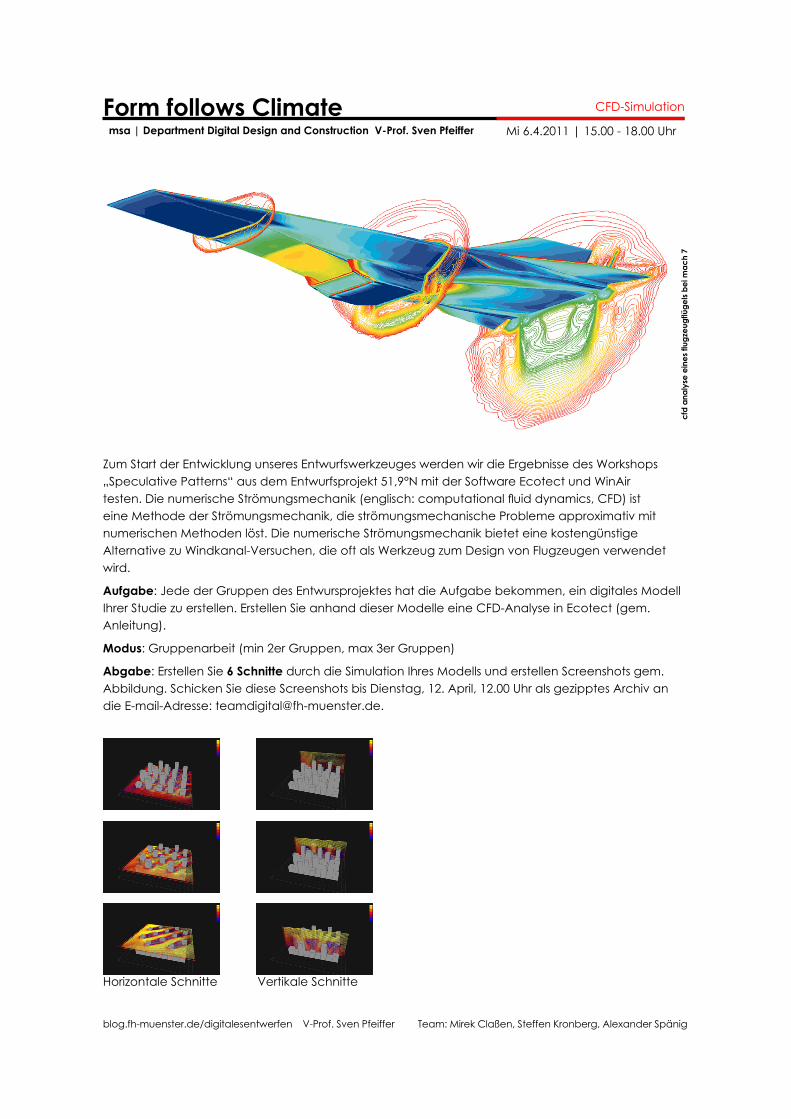
Zum Start der Entwicklung unseres Entwurfswerkzeuges werden wir die Ergebnisse des Workshops „Speculative Patterns“ aus dem Entwurfsprojekt 51,9°N mit der Software Ecotect und WinAir testen. Die numerische Strömungsmechanik (englisch: computational fluid dynamics, CFD) ist eine Methode der Strömungsmechanik, die strömungsmechanische Probleme approximativ mit numerischen Methoden löst. Die numerische Strömungsmechanik bietet eine kostengünstige Alternative zu Windkanal-Versuchen, die oft als Werkzeug zum Design von Flugzeugen verwendet wird.
Aufgabe: Jede der Gruppen des Entwursprojektes hat die Aufgabe bekommen, ein digitales Modell Ihrer Studie zu erstellen. Erstellen Sie anhand dieser Modelle eine CFD-Analyse in Ecotect (gem. Anleitung).
Modus: Gruppenarbeit (min 2er Gruppen, max 3er Gruppen)
Abgabe: Erstellen Sie 6 Schnitte durch die Simulation Ihres Modells und erstellen Screenshots gem. Abbildung. Schicken Sie diese Screenshots bis Dienstag, 12. April, 12.00 Uhr als gezipptes Archiv an die E-mail-Adresse: [email protected].
blog.fh-muenster.de/digitalesentwerfen V-Prof. Sven Pfeiffer Team: Mirek Claßen, Steffen Kronberg, Alexander Spänig
Form follows Climate CFD-Simulation
Mi 6.4.2011 | 15.00 - 18.00 Uhr msa | Department Digital Design and Construction V-Prof. Sven Pfeiffer
cfd
anal
yse
eine
s flu
gzeu
gflü
gels
bei m
ach
7
Horizontale Schnitte Vertikale Schnitte

blog.fh-muenster.de/digitalesentwerfen V-Prof. Sven Pfeiffer Team: Mirek Claßen, Steffen Kronberg, Alexander Spänig
Form follows Climate msa | Department Digital Design and Construction V-Prof. Sven Pfeiffer
CFD-Simulation
Mi 6.4.2011 | 15.00 - 18.00 Uhr
how to get_ecotect: http://students.autodesk.com/ (free for students)winair: https://blog.fh-muenster.de/digitalesentwerfen/eine-seite/software/
steps_1. import .dxf to ecotect2. define analysis grid3. create cfd data4. export cfd data to winair and run calculations5. load winair output file and discuss results
info_for this tutorial, I used Rhino 4 SR9, Ecotect Analysis 2011 and WinAir 1.4b
blog.fh-muenster.de/digitalesentwerfen V-Prof. Sven Pfeiffer Team: Mirek Claßen, Steffen Kronberg, Alexander Spänig
Form follows Climate msa | Department Digital Design and Construction V-Prof. Sven Pfeiffer
CFD-Simulation
Mi 6.4.2011 | 15.00 - 18.00 Uhr
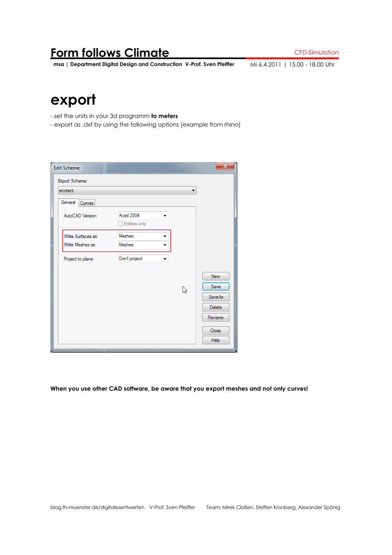
export- set the units in your 3d programm to meters- export as .dxf by using the following options (example from rhino)
When you use other CAD software, be aware that you export meshes and not only curves!
blog.fh-muenster.de/digitalesentwerfen V-Prof. Sven Pfeiffer Team: Mirek Claßen, Steffen Kronberg, Alexander Spänig
Form follows Climate msa | Department Digital Design and Construction V-Prof. Sven Pfeiffer
CFD-Simulation
Mi 6.4.2011 | 15.00 - 18.00 Uhr
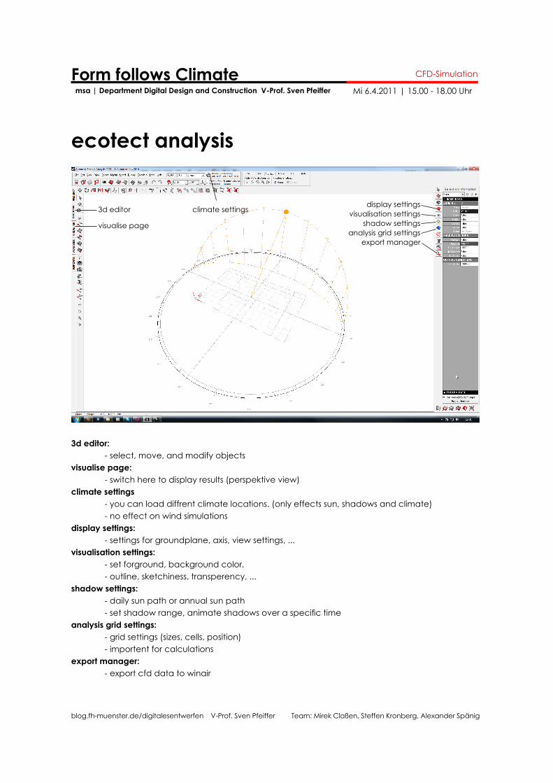
ecotect analysis
3d editor climate settings
visualise pageanalysis grid settings
visualisation settingsshadow settings
display settings
export manager
3d editor: - select, move, and modify objectsvisualise page: - switch here to display results (perspektive view)climate settings - you can load diffrent climate locations. (only effects sun, shadows and climate) - no effect on wind simulationsdisplay settings: - settings for groundplane, axis, view settings, ...visualisation settings: - set forground, background color, - outline, sketchiness, transperency, ...shadow settings: - daily sun path or annual sun path - set shadow range, animate shadows over a specific timeanalysis grid settings: - grid settings (sizes, cells, position) - importent for calculationsexport manager: - export cfd data to winair
blog.fh-muenster.de/digitalesentwerfen V-Prof. Sven Pfeiffer Team: Mirek Claßen, Steffen Kronberg, Alexander Spänig
Form follows Climate msa | Department Digital Design and Construction V-Prof. Sven Pfeiffer
CFD-Simulation
Mi 6.4.2011 | 15.00 - 18.00 Uhr
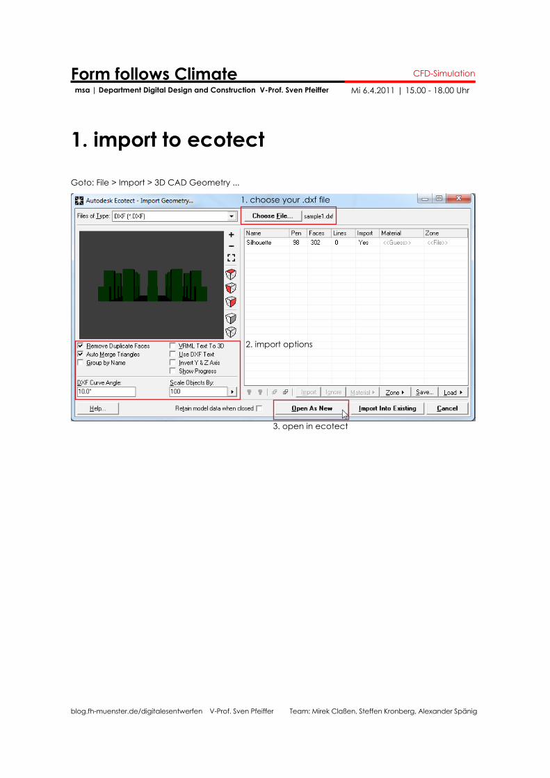
1. import to ecotect
Goto: File > Import > 3D CAD Geometry ...
1. choose your .dxf file
2. import options
3. open in ecotect
blog.fh-muenster.de/digitalesentwerfen V-Prof. Sven Pfeiffer Team: Mirek Claßen, Steffen Kronberg, Alexander Spänig
Form follows Climate msa | Department Digital Design and Construction V-Prof. Sven Pfeiffer
CFD-Simulation
Mi 6.4.2011 | 15.00 - 18.00 Uhr
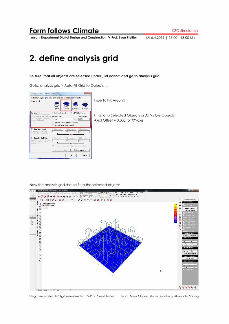
2. define analysis grid
Goto: analysis grid > Auto-Fit Grid to Objects ...
Type to Fit: Around
Fit Grid to Selected Objects or All Visible ObjectsAxial Offset = 0.000 for XY-axis
Now the analysis grid should fit to the selected objects
Be sure, that all objects are selected under „3d editor“ and go to analysis grid
blog.fh-muenster.de/digitalesentwerfen V-Prof. Sven Pfeiffer Team: Mirek Claßen, Steffen Kronberg, Alexander Spänig
Form follows Climate msa | Department Digital Design and Construction V-Prof. Sven Pfeiffer
CFD-Simulation
Mi 6.4.2011 | 15.00 - 18.00 Uhr
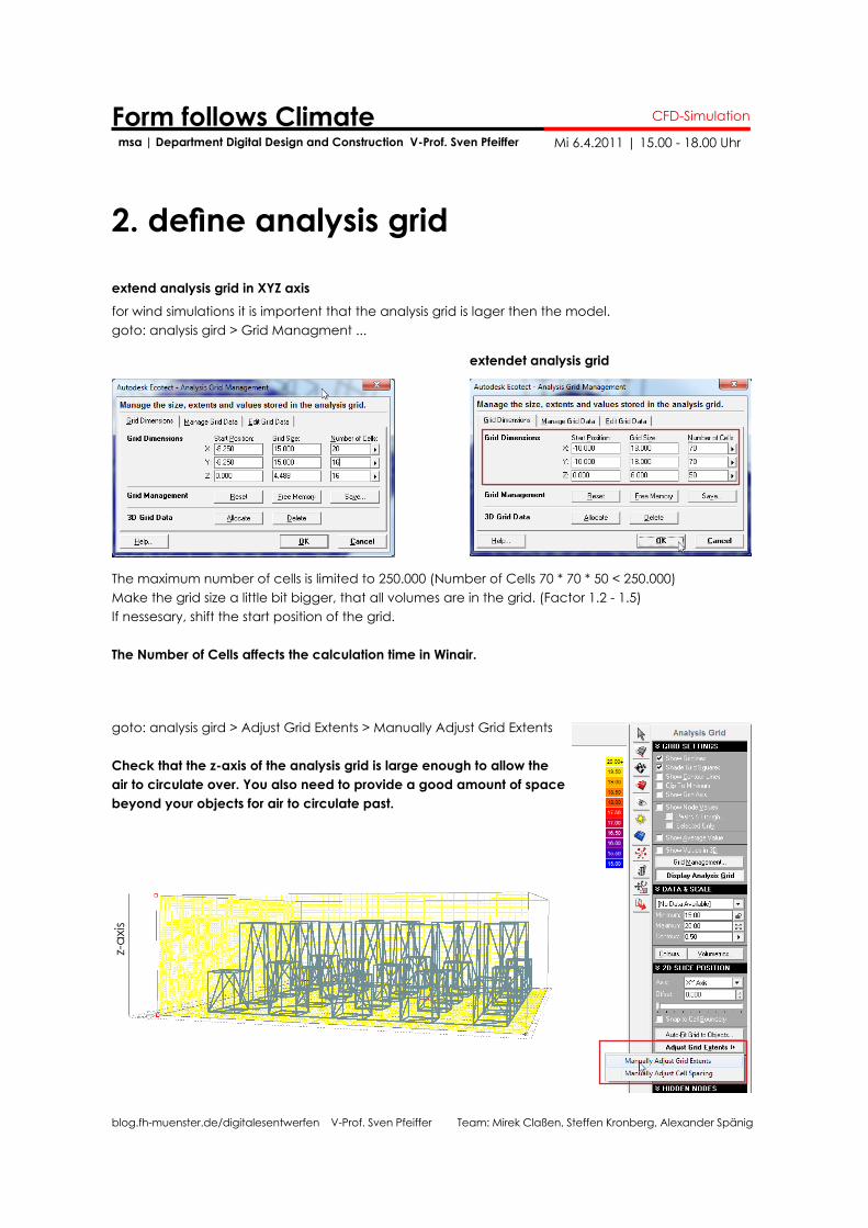
2. define analysis grid
extend analysis grid in XYZ axisfor wind simulations it is importent that the analysis grid is lager then the model. goto: analysis gird > Grid Managment ...
extendet analysis grid
The maximum number of cells is limited to 250.000 (Number of Cells 70 * 70 * 50 < 250.000)Make the grid size a little bit bigger, that all volumes are in the grid. (Factor 1.2 - 1.5)If nessesary, shift the start position of the grid.
The Number of Cells affects the calculation time in Winair.
goto: analysis gird > Adjust Grid Extents > Manually Adjust Grid Extents
Check that the z-axis of the analysis grid is large enough to allow the air to circulate over. You also need to provide a good amount of space beyond your objects for air to circulate past.
z-ax
is
blog.fh-muenster.de/digitalesentwerfen V-Prof. Sven Pfeiffer Team: Mirek Claßen, Steffen Kronberg, Alexander Spänig
Form follows Climate msa | Department Digital Design and Construction V-Prof. Sven Pfeiffer
CFD-Simulation
Mi 6.4.2011 | 15.00 - 18.00 Uhr
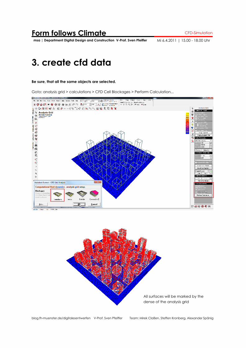
3. create cfd data
Be sure, that all the same objects are selected.
Goto: analysis grid > calculations > CFD Cell Blockages > Perform Calculation...
All surfaces will be marked by the dense of the analysis grid
blog.fh-muenster.de/digitalesentwerfen V-Prof. Sven Pfeiffer Team: Mirek Claßen, Steffen Kronberg, Alexander Spänig
Form follows Climate msa | Department Digital Design and Construction V-Prof. Sven Pfeiffer
CFD-Simulation
Mi 6.4.2011 | 15.00 - 18.00 Uhr
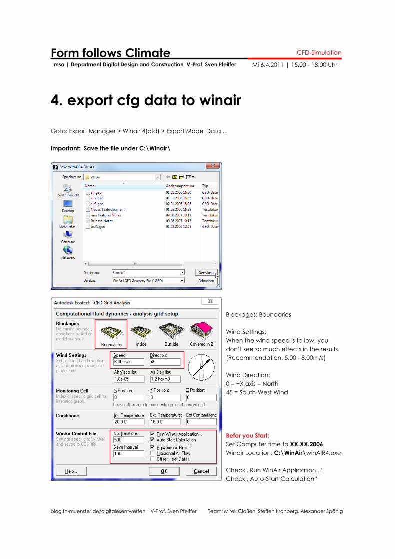
4. export cfg data to winair
Goto: Export Manager > Winair 4(cfd) > Export Model Data ...
Important: Save the file under C:\Winair\
Blockages: Boundaries
Wind Settings: When the wind speed is to low, you don‘t see so much effects in the results. (Recommendation: 5.00 - 8.00m/s)
Wind Direction:0 = +X axis = North45 = South-West Wind
Befor you Start:Set Computer time to XX.XX.2006Winair Location: C:\WinAir\winAIR4.exe
Check „Run WinAir Application...“Check „Auto-Start Calculation“
blog.fh-muenster.de/digitalesentwerfen V-Prof. Sven Pfeiffer Team: Mirek Claßen, Steffen Kronberg, Alexander Spänig
Form follows Climate msa | Department Digital Design and Construction V-Prof. Sven Pfeiffer
CFD-Simulation
Mi 6.4.2011 | 15.00 - 18.00 Uhr
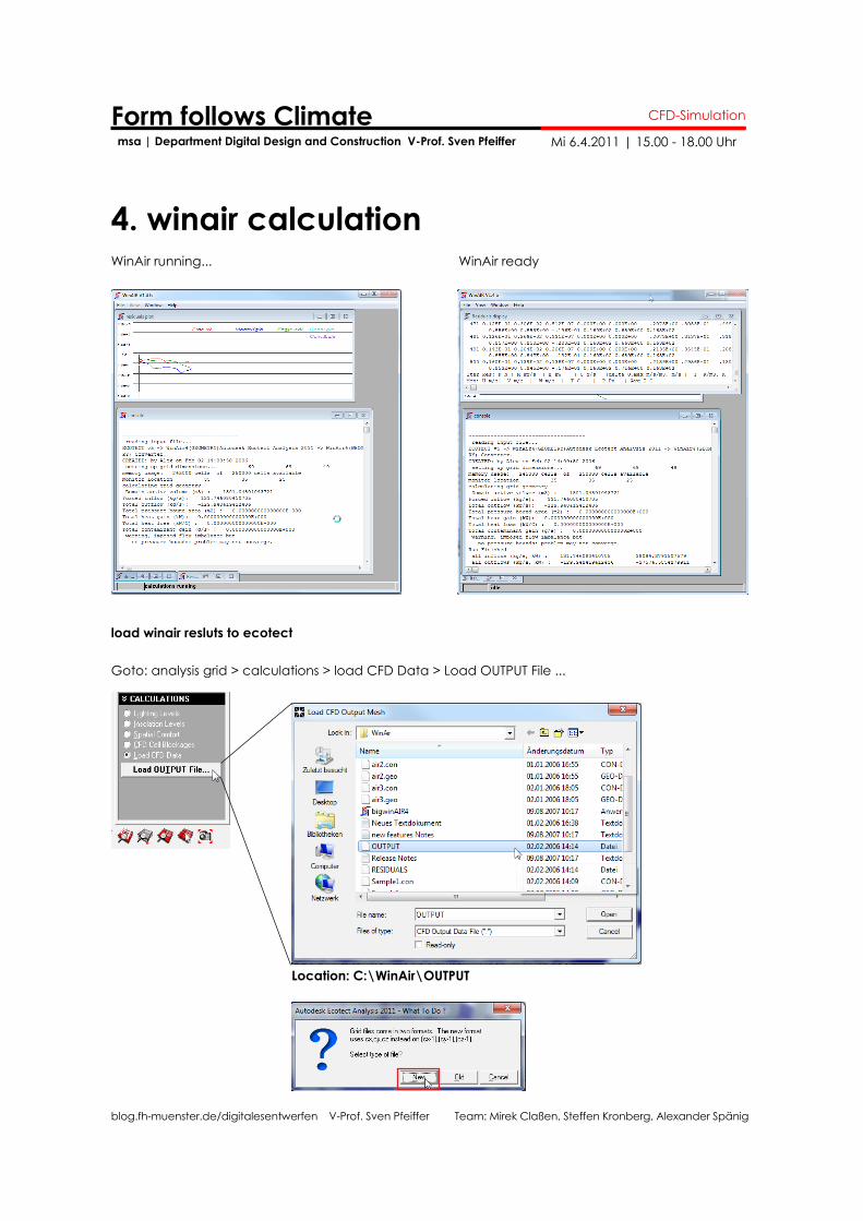
4. winair calculationWinAir running...
load winair resluts to ecotect
Goto: analysis grid > calculations > load CFD Data > Load OUTPUT File ...
WinAir ready
Location: C:\WinAir\OUTPUT
blog.fh-muenster.de/digitalesentwerfen V-Prof. Sven Pfeiffer Team: Mirek Claßen, Steffen Kronberg, Alexander Spänig
Form follows Climate msa | Department Digital Design and Construction V-Prof. Sven Pfeiffer
CFD-Simulation
Mi 6.4.2011 | 15.00 - 18.00 Uhr
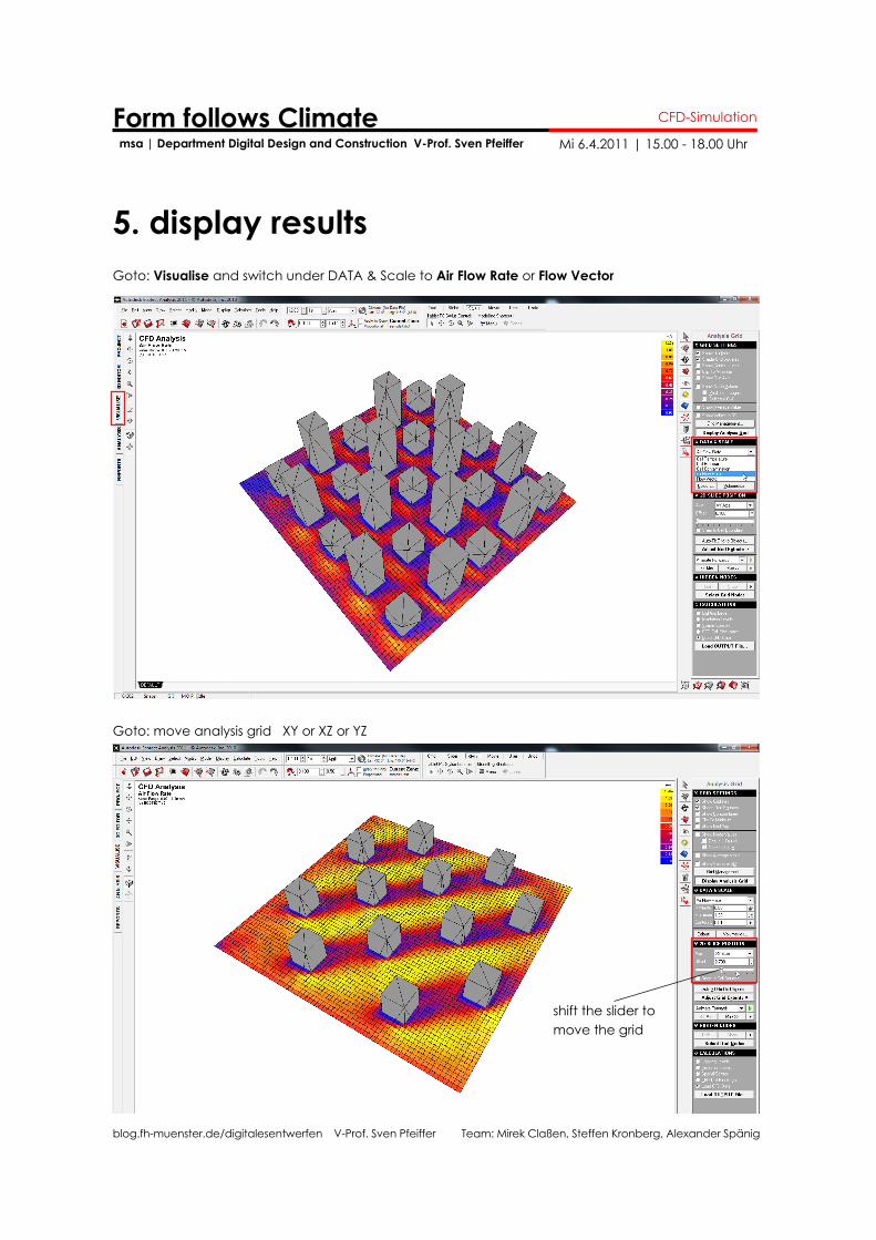
Goto: Visualise and switch under DATA & Scale to Air Flow Rate or Flow Vector
Goto: move analysis grid XY or XZ or YZ
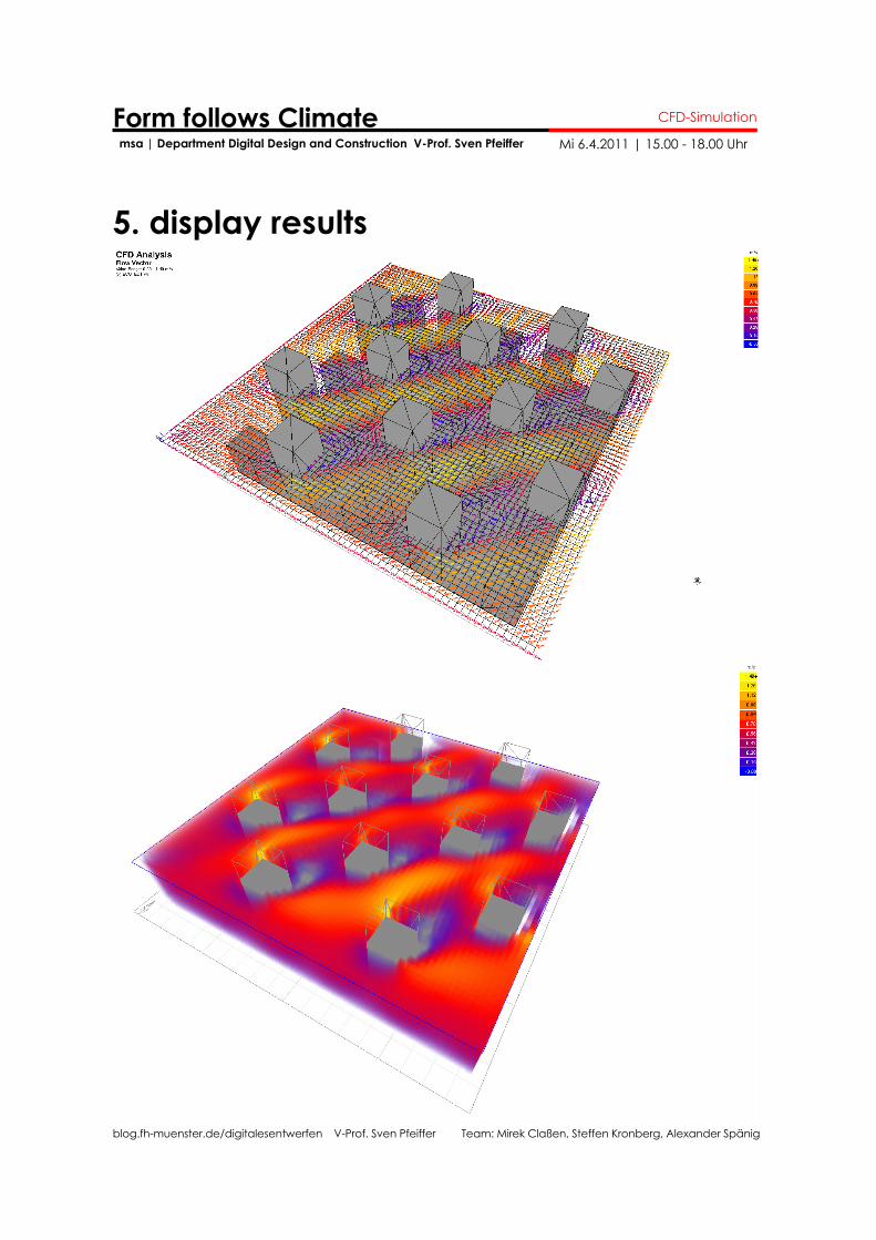
5. display results
shift the slider to move the grid
blog.fh-muenster.de/digitalesentwerfen V-Prof. Sven Pfeiffer Team: Mirek Claßen, Steffen Kronberg, Alexander Spänig
Form follows Climate msa | Department Digital Design and Construction V-Prof. Sven Pfeiffer
CFD-Simulation
Mi 6.4.2011 | 15.00 - 18.00 Uhr
5. display results