Hardware installation plan - WICTIP PAF 140 S A4_de.pdf · Hardware installation plan ... Drill out...
20
09.2017 27701 www.wicona.com WICLINE 90 SG PAF 140 S Hardware installation plan for Parallel opening hardware up to 140 kg, FAH ≤ 2 m Beschlag-Einbauplan für Parallel-Ausstell-Beschlag bis 140 kg, FAH ≤ 2 m
Transcript of Hardware installation plan - WICTIP PAF 140 S A4_de.pdf · Hardware installation plan ... Drill out...
09.201727701
www.wicona.com
WICLINE 90 SGPAF 140 S
Hardware installation plan
for Parallel opening hardware up to 140 kg, FAH ≤ 2 m
Beschlag-Einbauplan
für Parallel-Ausstell-Beschlag bis 140 kg, FAH ≤ 2 m

2 09.2017 27701 Änderungen vorbehalten. Subject to alterations.PAF 140 S
Wichtige Informationen 4Important information
Zulässige Flügelgrößen 5Admissible sash sizes
Zulässige Formatgrößen 6Admissible format sizes
Beschlagübersicht 7Hardware overview
Beschlagübersicht Grundbeschlag 8Overview basic hardware
Abkürzungen 9Abbreviations
Eckumlenkung mit Schaltsperre 16Corner transmision with fail save device
Wartung und Montage 18Service and installation
Wartungshinweise 19Maintenance instructions
Montagehinweise 19Instructions for mounting
Lehren und Werkzeuge 20Templates and tools
Öffnen Schieberstangenkanal 20Open sliding rod channel
Profilschnitt 20Profile section
ContentsGB
Änderungen vorbehalten. Subject to alterations. 27701 09.2017 3PAF 140 S
InhaltD
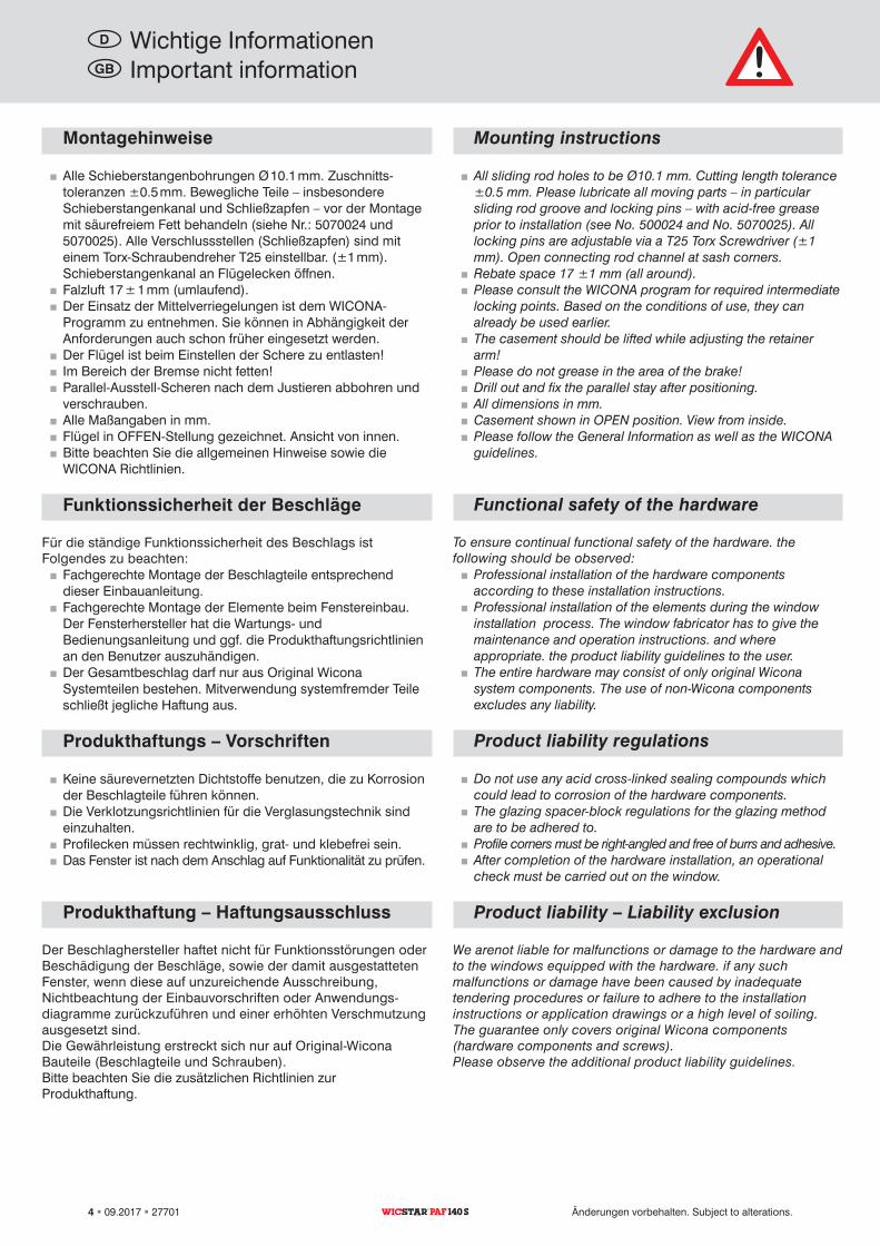
Mounting instructions
�� All sliding rod holes to be Ø10.1 mm. Cutting length tolerance ±0.5 mm. Please lubricate all moving parts – in particular sliding rod groove and locking pins – with acid-free grease prior to installation (see No. 500024 and No. 5070025). All locking pins are adjustable via a T25 Torx Screwdriver (±1 mm). Open connecting rod channel at sash corners.�� Rebate space 17 ±1 mm (all around).�� Please consult the WICONA program for required intermediate locking points. Based on the conditions of use, they can already be used earlier.�� The casement should be lifted while adjusting the retainer arm!�� Please do not grease in the area of the brake!�� Drill out and fix the parallel stay after positioning.�� All dimensions in mm.�� Casement shown in OPEN position. View from inside.�� Please follow the General Information as well as the WICONA guidelines.
Functional safety of the hardware
To ensure continual functional safety of the hardware. the following should be observed:�� Professional installation of the hardware components according to these installation instructions.�� Professional installation of the elements during the window installation process. The window fabricator has to give the maintenance and operation instructions. and where appropriate. the product liability guidelines to the user.�� The entire hardware may consist of only original Wicona system components. The use of non-Wicona components excludes any liability.
Product liability regulations
�� Do not use any acid cross-linked sealing compounds which could lead to corrosion of the hardware components. �� The glazing spacer-block regulations for the glazing method are to be adhered to.�� Profile corners must be right-angled and free of burrs and adhesive.�� After completion of the hardware installation, an operational check must be carried out on the window.
Product liability – Liability exclusion
We arenot liable for malfunctions or damage to the hardware and to the windows equipped with the hardware. if any such malfunctions or damage have been caused by inadequate tendering procedures or failure to adhere to the installation instructions or application drawings or a high level of soiling. The guarantee only covers original Wicona components (hardware components and screws). Please observe the additional product liability guidelines.
Important informationGB
4 09.2017 27701 Änderungen vorbehalten. Subject to alterations.PAF 140 S
Montagehinweise
�� Alle Schieberstangenbohrungen Ø 10.1 mm. Zuschnittstoleranzen ±0.5 mm. Bewegliche Teile – insbesondere Schieberstangenkanal und Schließzapfen – vor der Montage mit säurefreiem Fett behandeln (siehe Nr.: 5070024 und 5070025). Alle Verschlussstellen (Schließzapfen) sind mit einem TorxSchraubendreher T25 einstellbar. (±1 mm). Schieberstangenkanal an Flügelecken öffnen.�� Falzluft 17 ± 1 mm (umlaufend).�� Der Einsatz der Mittelverriegelungen ist dem WICONAProgramm zu entnehmen. Sie können in Abhängigkeit der Anforderungen auch schon früher eingesetzt werden.�� Der Flügel ist beim Einstellen der Schere zu entlasten!�� Im Bereich der Bremse nicht fetten!�� ParallelAusstellScheren nach dem Justieren abbohren und verschrauben.�� Alle Maßangaben in mm.�� Flügel in OFFENStellung gezeichnet. Ansicht von innen.�� Bitte beachten Sie die allgemeinen Hinweise sowie die WICONA Richtlinien.
Funktionssicherheit der Beschläge
Für die ständige Funktionssicherheit des Beschlags ist Folgendes zu beachten:�� Fachgerechte Montage der Beschlagteile entsprechend dieser Einbauanleitung.�� Fachgerechte Montage der Elemente beim Fenstereinbau. Der Fensterhersteller hat die Wartungs und Bedienungsanleitung und ggf. die Produkthaftungsrichtlinien an den Benutzer auszuhändigen.�� Der Gesamtbeschlag darf nur aus Original Wicona Systemteilen bestehen. Mitverwendung systemfremder Teile schließt jegliche Haftung aus.
Produkthaftungs – Vorschriften
�� Keine säurevernetzten Dichtstoffe benutzen, die zu Korrosion der Beschlagteile führen können.�� Die Verklotzungsrichtlinien für die Verglasungstechnik sind einzuhalten.�� Profilecken müssen rechtwinklig, grat und klebefrei sein.�� Das Fenster ist nach dem Anschlag auf Funktionalität zu prüfen.
Produkthaftung – Haftungsausschluss
Der Beschlaghersteller haftet nicht für Funktionsstörungen oder Beschädigung der Beschläge, sowie der damit ausgestatteten Fenster, wenn diese auf unzureichende Ausschreibung, Nichtbeachtung der Einbauvorschriften oder Anwendungsdiagramme zurückzuführen und einer erhöhten Verschmutzung ausgesetzt sind. Die Gewährleistung erstreckt sich nur auf OriginalWicona Bauteile (Beschlagteile und Schrauben).Bitte beachten Sie die zusätzlichen Richtlinien zur Produkthaftung.
Wichtige InformationenD
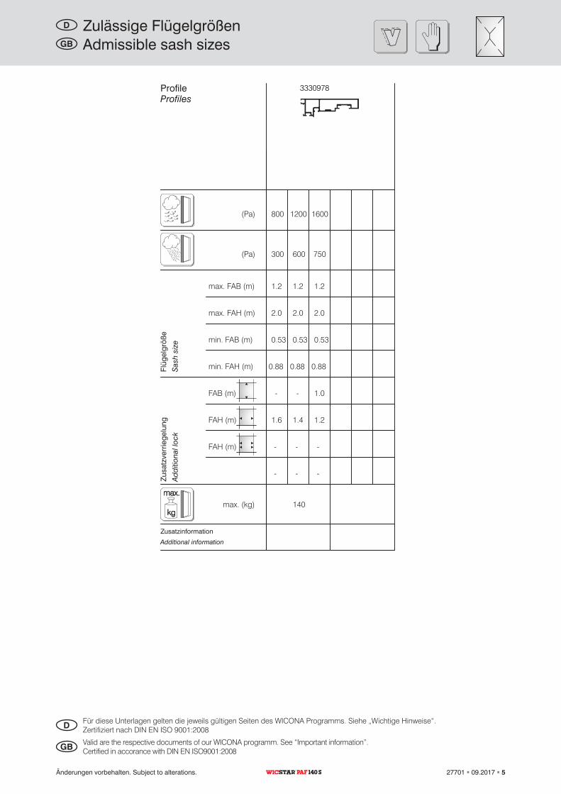
(Pa)
0.53
1.6 1.4 1.2
140max. (kg)
- -
1.2 1.2 1.2
2.0
1.0
- - -
0.88
2.0 2.0
0.53 0.53
max. FAB (m)
max. FAH (m)
min. FAB (m)
min. FAH (m)
FAH (m)
FAB (m)
FAH (m)
0.88 0.88
1600800 1200
750300 600
- - -
(Pa)
3330978
kg
max.
Admissible sash sizesGB
Additional information
Add
ition
al lo
ckSa
sh s
ize
Profiles
Valid are the respective documents of our WICONA programm. See “Important information”.Certified in accorance with DIN EN ISO9001:2008GB
Änderungen vorbehalten. Subject to alterations. 27701 09.2017 5PAF 140 S
Zulässige FlügelgrößenD
Zusatzinformation
Zusa
tzve
rrie
gelu
ngFl
ügel
größ
e
Profile
Für diese Unterlagen gelten die jeweils gültigen Seiten des WICONA Programms. Siehe „Wichtige Hinweise“.Zertifiziert nach DIN EN ISO 9001:2008D
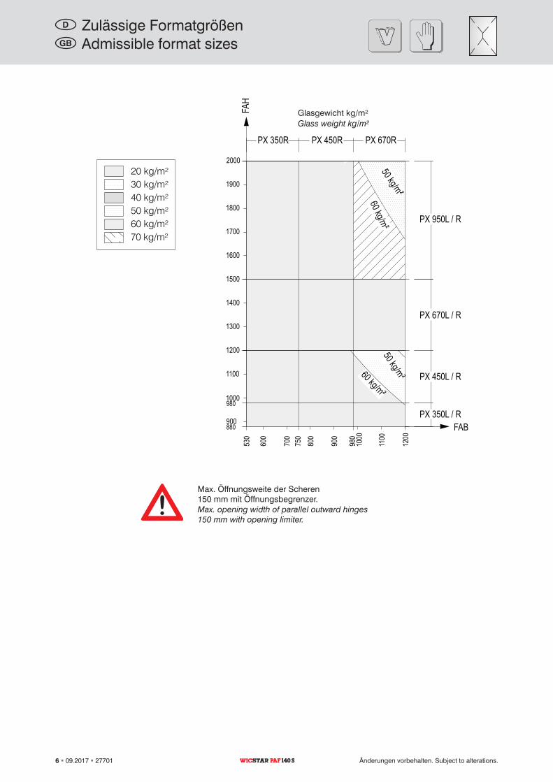
1200
750
980
1200
PX 350L / R
PX 450L / R
PX 670L / R
PX 950L / R
900
1100
1000
1300
1400
1500
1600
1700
1100
900
800
700
600
1800
1000
PX 350R PX 670RPX 450R
1900
200050 kg/m²
60 kg/m²
880
980
50 kg/m²60 kg/m²
530
FAH
FAB
20 kg/m²30 kg/m²40 kg/m²50 kg/m²60 kg/m²70 kg/m²
Admissible format sizesGB
Glass weight kg/m²
Max. opening width of parallel outward hinges 150 mm with opening limiter.
6 09.2017 27701 Änderungen vorbehalten. Subject to alterations.PAF 140 S
Zulässige FormatgrößenD
Glasgewicht kg/m²
Max. Öffnungsweite der Scheren 150 mm mit Öffnungsbegrenzer.
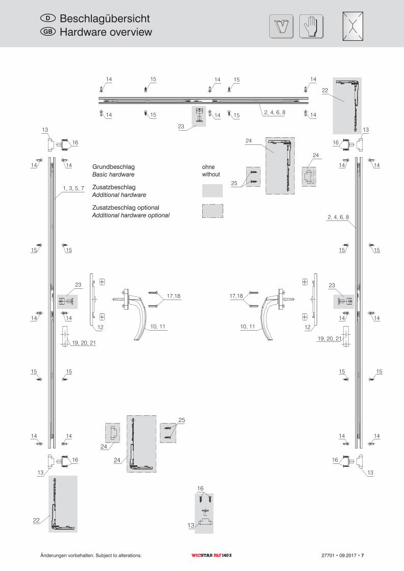
2, 4, 6, 8
13
13
14 15
14 15
14 15
14 15
14
14
1414
1515
1414
1515
1414
16
16
19, 20, 21
1, 3, 5, 7
23
13
14 14
15 15
14 14
15 15
14 14
16
19, 20, 21
13
16
2, 4, 6, 8
23
10, 11
17,18
12 10, 11
17,18
12
13
16
22
24
24
25
23
24
24
25
22
withoutBasic hardware
Additional hardware
Additional hardware optional
GB Hardware overview
Änderungen vorbehalten. Subject to alterations. 27701 09.2017 7PAF 140 S
Grundbeschlag ohne
Zusatzbeschlag
Zusatzbeschlag optional
D Beschlagübersicht
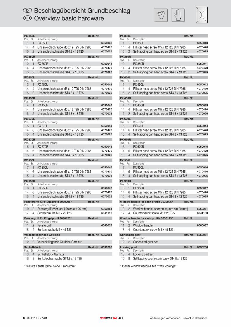
PX 350L Ref. No.Pos. Pc. Description
1 1 PX 350L 6050040
14 4 Fillister head screw M5 x 12 T25 DIN 7985 4070470
15 2 Selftapping pan head screw ST4.8 x 13 T25 4070025
PX 350R Ref. No.Pos. Pc. Description
2 1 PX 350R 6050041
14 4 Fillister head screw M5 x 12 T25 DIN 7985 4070470
15 2 Selftapping pan head screw ST4.8 x 13 T25 4070025
PX 450L Ref. No.Pos. Pc. Description
3 1 PX 450L 6050042
14 4 Fillister head screw M5 x 12 T25 DIN 7985 4070470
15 2 Selftapping pan head screw ST4.8 x 13 T25 4070025
PX 450R Ref. No.Pos. Pc. Description
4 1 PX 450R 6050043
14 4 Fillister head screw M5 x 12 T25 DIN 7985 4070470
15 2 Selftapping pan head screw ST4.8 x 13 T25 4070025
PX 670L Ref. No.Pos. Pc. Description
5 1 PX 670L 6050044
14 6 Fillister head screw M5 x 12 T25 DIN 7985 4070470
15 4 Selftapping pan head screw ST4.8 x 13 T25 4070025
PX 670R Ref. No.Pos. Pc. Description
6 1 PX 670R 6050045
14 6 Fillister head screw M5 x 12 T25 DIN 7985 4070470
15 4 Selftapping pan head screw ST4.8 x 13 T25 4070025
PX 950L Ref. No.Pos. Pc. Description
7 1 PX 950L 6050046
14 6 Fillister head screw M5 x 12 T25 DIN 7985 4070470
15 4 Selftapping pan head screw ST4.8 x 13 T25 4070025
PX 950R Ref. No.Pos. Pc. Description
8 1 PX 950R 6050047
14 6 Fillister head screw M5 x 12 T25 DIN 7985 4070470
15 4 Selftapping pan head screw ST4.8 x 13 T25 4070025
Window handle for sash profile 3030096* Ref. No.Pos. Pc. Description10 2 Window handle (shorten square pin 20 mm) 6960261
17 4 Counterssunk screw M5 x 25 T25 6041190
Window handle for sash profile 3030123* Ref. No.Pos. Pc. Description11 2 Window handle 6060037
18 4 Countersunk screw M5 x 45 T25Concealed gear Ref. No. 6050081Pos. Pc. Description12 2 Concealed gear set
Locking prart Ref. No. 6050200Pos. Pc. Description13 4 Locking part set16 8 Selftapping countersunk screw ST4.8 x 19 T25
* further window handles see "Product range"
GB Overview basic hardware
8 09.2017 27701 Änderungen vorbehalten. Subject to alterations.PAF 140 S
PX 350L Best.-Nr.Pos. St. Artikelbezeichnung
1 1 PX 350L 6050040
14 4 Linsenkopfschraube M5 x 12 T25 DIN 7985 4070470
15 2 Linsenblechschraube ST4.8 x 13 T25 4070025
PX 350R Best.-Nr.Pos. St. Artikelbezeichnung
2 1 PX 350R 6050041
14 4 Linsenkopfschraube M5 x 12 T25 DIN 7985 4070470
15 2 Linsenblechschraube ST4.8 x 13 T25 4070025
PX 450L Best.-Nr.Pos. St. Artikelbezeichnung
3 1 PX 450L 6050042
14 4 Linsenkopfschraube M5 x 12 T25 DIN 7985 4070470
15 2 Linsenblechschraube ST4.8 x 13 T25 4070025
PX 450R Best.-Nr.Pos. St. Artikelbezeichnung
4 1 PX 450R 6050043
14 4 Linsenkopfschraube M5 x 12 T25 DIN 7985 4070470
15 2 Linsenblechschraube ST4.8 x 13 T25 4070025
PX 670L Best.-Nr.Pos. St. Artikelbezeichnung
5 1 PX 670L 6050044
14 6 Linsenkopfschraube M5 x 12 T25 DIN 7985 4070470
15 4 Linsenblechschraube ST4.8 x 13 T25 4070025
PX 670R Best.-Nr.Pos. St. Artikelbezeichnung
6 1 PX 670R 6050045
14 6 Linsenkopfschraube M5 x 12 T25 DIN 7985 4070470
15 4 Linsenblechschraube ST4.8 x 13 T25 4070025
PX 950L Best.-Nr.Pos. St. Artikelbezeichnung
7 1 PX 950L 6050046
14 6 Linsenkopfschraube M5 x 12 T25 DIN 7985 4070470
15 4 Linsenblechschraube ST4.8 x 13 T25 4070025
PX 950R Best.-Nr.Pos. St. Artikelbezeichnung
8 1 PX 950R 6050047
14 6 Linsenkopfschraube M5 x 12 T25 DIN 7985 4070470
15 4 Linsenblechschraube ST4.8 x 13 T25 4070025
Fenstergriff für Flügelprofil 3030096* Best.-Nr.Pos. St. Artikelbezeichnung10 2 Fenstergriff (Vierkant kürzen auf 20 mm) 6960261
17 4 Senkschraube M5 x 25 T25 6041190
Fenstergriff für Flügelprofil 3030123* Best.-Nr.Pos. St. Artikelbezeichnung11 2 Fenstergriff 6060037
18 4 Senkschraube M5 x 45 T25Verdecktliegendes Getriebe Best.-Nr. 6050081Pos. St. Artikelbezeichnung12 2 Verdecktliegende Getriebe Garnitur
Schließstück Best.-Nr. 6050200Pos. St. Artikelbezeichnung13 4 Schließstück Garnitur16 8 Senkblechschraube ST4.8 x 19 T25
* weitere Fenstergriffe, siehe "Programm"
D Beschlagübersicht Grundbeschlag
RAB
RAH
RIH
RIB
FAB
FAH
FIB
FIH
FL
HG
FG
PZ
RZ
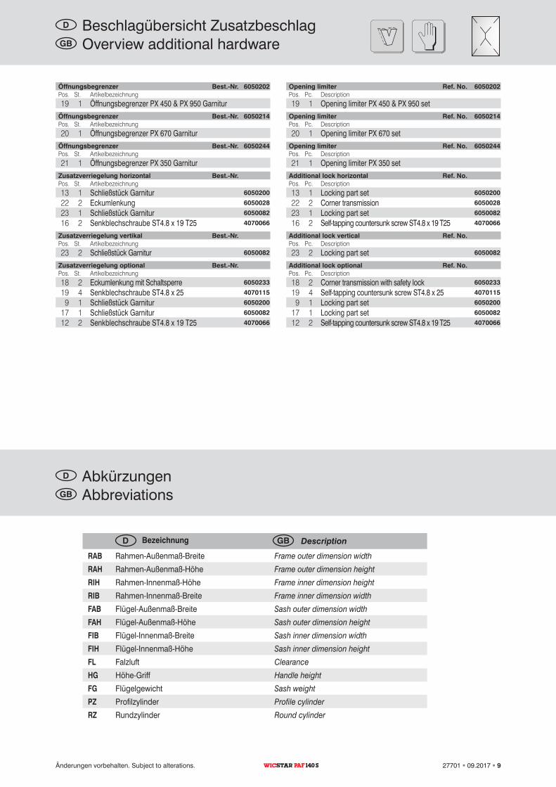
Opening limiter Ref. No. 6050202Pos. Pc. Description19 1 Opening limiter PX 450 & PX 950 set
Opening limiter Ref. No. 6050214Pos. Pc. Description20 1 Opening limiter PX 670 set
Opening limiter Ref. No. 6050244Pos. Pc. Description21 1 Opening limiter PX 350 set
Additional lock horizontal Ref. No.Pos. Pc. Description13 1 Locking part set 6050200
22 2 Corner transmission 6050028
23 1 Locking part set 6050082
16 2 Selftapping countersunk screw ST4.8 x 19 T25 4070066
Additional lock vertical Ref. No.Pos. Pc. Description23 2 Locking part set 6050082
Additional lock optional Ref. No.Pos. Pc. Description18 2 Corner transmission with safety lock 6050233
19 4 Selftapping countersunk screw ST4.8 x 25 4070115
9 1 Locking part set 6050200
17 1 Locking part set 6050082
12 2 Selftapping countersunk screw ST4.8 x 19 T25 4070066
GB Overview additional hardware
AbbreviationsGB
Description
Frame outer dimension width
Frame outer dimension height
Frame inner dimension height
Frame inner dimension width
Sash outer dimension width
Sash outer dimension height
Sash inner dimension width
Sash inner dimension height
Clearance
Handle height
Sash weight
Profile cylinder
Round cylinder
GB
Änderungen vorbehalten. Subject to alterations. 27701 09.2017 9PAF 140 S
Öffnungsbegrenzer Best.-Nr. 6050202Pos. St. Artikelbezeichnung19 1 Öffnungsbegrenzer PX 450 & PX 950 Garnitur
Öffnungsbegrenzer Best.-Nr. 6050214Pos. St. Artikelbezeichnung20 1 Öffnungsbegrenzer PX 670 Garnitur
Öffnungsbegrenzer Best.-Nr. 6050244Pos. St. Artikelbezeichnung21 1 Öffnungsbegrenzer PX 350 Garnitur
Zusatzverriegelung horizontal Best.-Nr.Pos. St. Artikelbezeichnung13 1 Schließstück Garnitur 6050200
22 2 Eckumlenkung 6050028
23 1 Schließstück Garnitur 6050082
16 2 Senkblechschraube ST4.8 x 19 T25 4070066
Zusatzverriegelung vertikal Best.-Nr.Pos. St. Artikelbezeichnung23 2 Schließstück Garnitur 6050082
Zusatzverriegelung optional Best.-Nr.Pos. St. Artikelbezeichnung18 2 Eckumlenkung mit Schaltsperre 6050233
19 4 Senkblechschraube ST4.8 x 25 4070115
9 1 Schließstück Garnitur 6050200
17 1 Schließstück Garnitur 6050082
12 2 Senkblechschraube ST4.8 x 19 T25 4070066
D Beschlagübersicht Zusatzbeschlag
AbkürzungenD
Bezeichnung
RahmenAußenmaßBreite
RahmenAußenmaßHöhe
RahmenInnenmaßHöhe
RahmenInnenmaßBreite
FlügelAußenmaßBreite
FlügelAußenmaßHöhe
FlügelInnenmaßBreite
FlügelInnenmaßHöhe
Falzluft
HöheGriff
Flügelgewicht
Profilzylinder
Rundzylinder
D
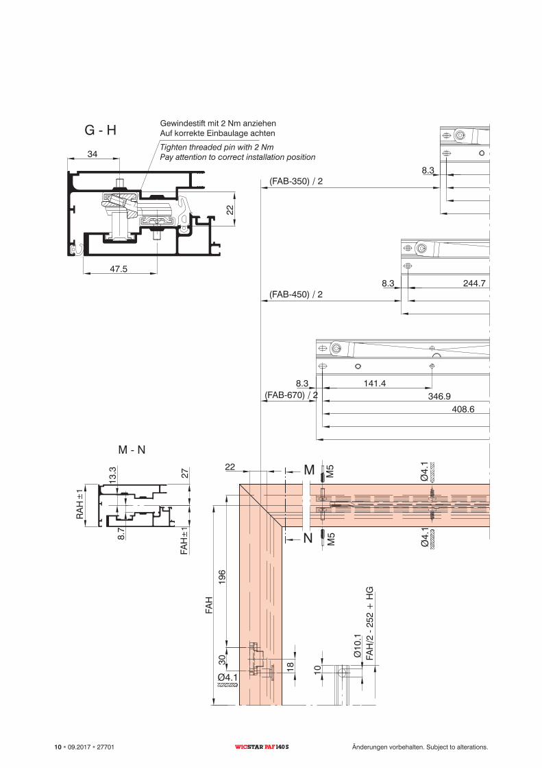
Ø4.
1
Ø4.
1
Ø4.1
30
H
G
N
M
G H
M N
3011021
199.1
RA
H ±
1
FAH
±1
27
13.3
8.7
FAH
196
22
Ø4.
1
M5
M5
M5
M5
M5
M5
Ø4.
1Ø4.1
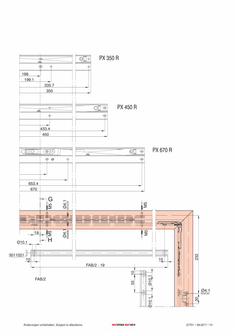
PX 350 R
PX 450 R
PX 670 R
8.3 168
335.7
8.3 244.7433.4
8.3 141.4346.9
408.6653.4
(FAB670) / 2
(FAB450) / 2
(FAB350) / 2
350
450
670
FAB/2 19
FAB/2
Ø10.1
1010
18
232
10
Ø10
.1
18
FAH
/2
252
+ H
G
Ø10
.1
1055
30
34
47.5
22
Ø10
.1
Tighten threaded pin with 2 NmPay attention to correct installation position
10 09.2017 27701 Änderungen vorbehalten. Subject to alterations.PAF 140 S
Gewindestift mit 2 Nm anziehenAuf korrekte Einbaulage achten
Ø4.
1
Ø4.
1
Ø4.1
30
H
G
N
M
G H
M N
3011021
199.1
RA
H ±
1
FAH
±1
27
13.3
8.7
FAH
196
22
Ø4.
1
M5
M5
M5
M5
M5
M5
Ø4.
1
Ø4.1
PX 350 R
PX 450 R
PX 670 R
8.3 168
335.7
8.3 244.7433.4
8.3 141.4346.9
408.6653.4
(FAB670) / 2
(FAB450) / 2
(FAB350) / 2
350
450
670
FAB/2 19
FAB/2
Ø10.1
1010
18
232
10
Ø10
.1
18
FAH
/2
252
+ H
G
Ø10
.1
1055
30
34
47.5
22
Ø10
.1
Änderungen vorbehalten. Subject to alterations. 27701 09.2017 11PAF 140 S
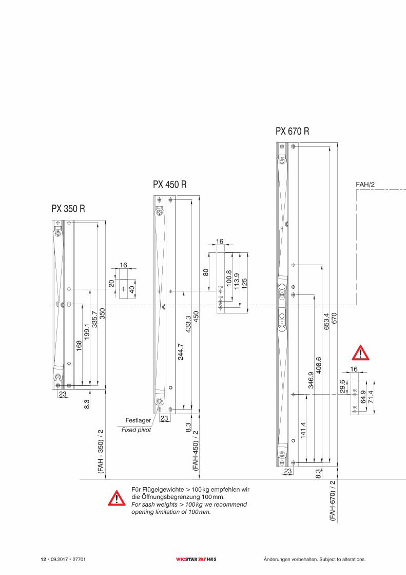
150
100
50
150
100
50
150
100
PX 350 R
PX 450 R
PX 670 R
PX 950 R
Ø4.1
Ø4.1
450
924.
6
350
8.3
141.
4
8.3
8.3
199.
1
30
L465
670
FAB/2 55
FAB
Ø10.1 Ø10.1
1010
FAH
/2
197
HG
1055
Ø10
.1
23
23
23
23
18.2
244.
747
6.9 70
1.7
908
346.
9 408.
665
3.4
244.
743
3.3
168
335.
7
16
80
100.
811
3.9
125
1664
.971
.4
16
80
100.
811
3.9
125
16
20
40
18
FAB/2 213.3
196
30
Ø10
.1
112
46H
G
74
HG
*
FAH
/2
252
+ H
G
46
29.6
(FA
H9
30)/
2
(FA
H4
50)
/ 2
(FA
H6
70)
/ 2
(FA
H
350)
/ 2
8.3
Ø10
.1
M5 M5
Ø4.1
M5 M5
M5 M5
Ø4.1
Ø4.1
Ø4.
1
3011021
FAB/2
FAH
/2FAH/2
For sash weights > 100 kg we recommend opening limitation of 100 mm.
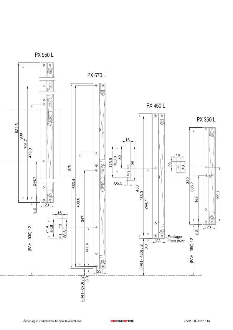
Fixed pivot
12 09.2017 27701 Änderungen vorbehalten. Subject to alterations.PAF 140 S
Für Flügelgewichte > 100 kg empfehlen wir die Öffnungsbegrenzung 100 mm.
Festlager
150
100
50
150
100
50
150
100
PX 350 R
PX 450 R
PX 670 R
PX 950 R
Ø4.1
Ø4.1
450
924.
6
350
8.3
141.
4
8.3
8.3
199.
1
30
L465
670
FAB/2 55
FAB
Ø10.1 Ø10.1
1010
FAH
/2
197
HG
1055
Ø10
.1
23
23
23
23
18.2
244.
747
6.9 70
1.7
908
346.
9 408.
665
3.4
244.
743
3.3
168
335.
7
16
80
100.
811
3.9
125
16
64.9
71.4
16
80
100.
811
3.9
125
16
20
40
18
FAB/2 213.3
196
30
Ø10
.1
112
46H
G
74
HG
*
FAH
/2
252
+ H
G
46
29.6
(FA
H9
30)/
2
(FA
H4
50)
/ 2
(FA
H6
70)
/ 2
(FA
H
350)
/ 2
8.3
Ø10
.1
M5 M5
Ø4.1
M5 M5
M5 M5
Ø4.1
Ø4.1
Ø4.
1
3011021
FAB/2
FAH
/2FAH/2
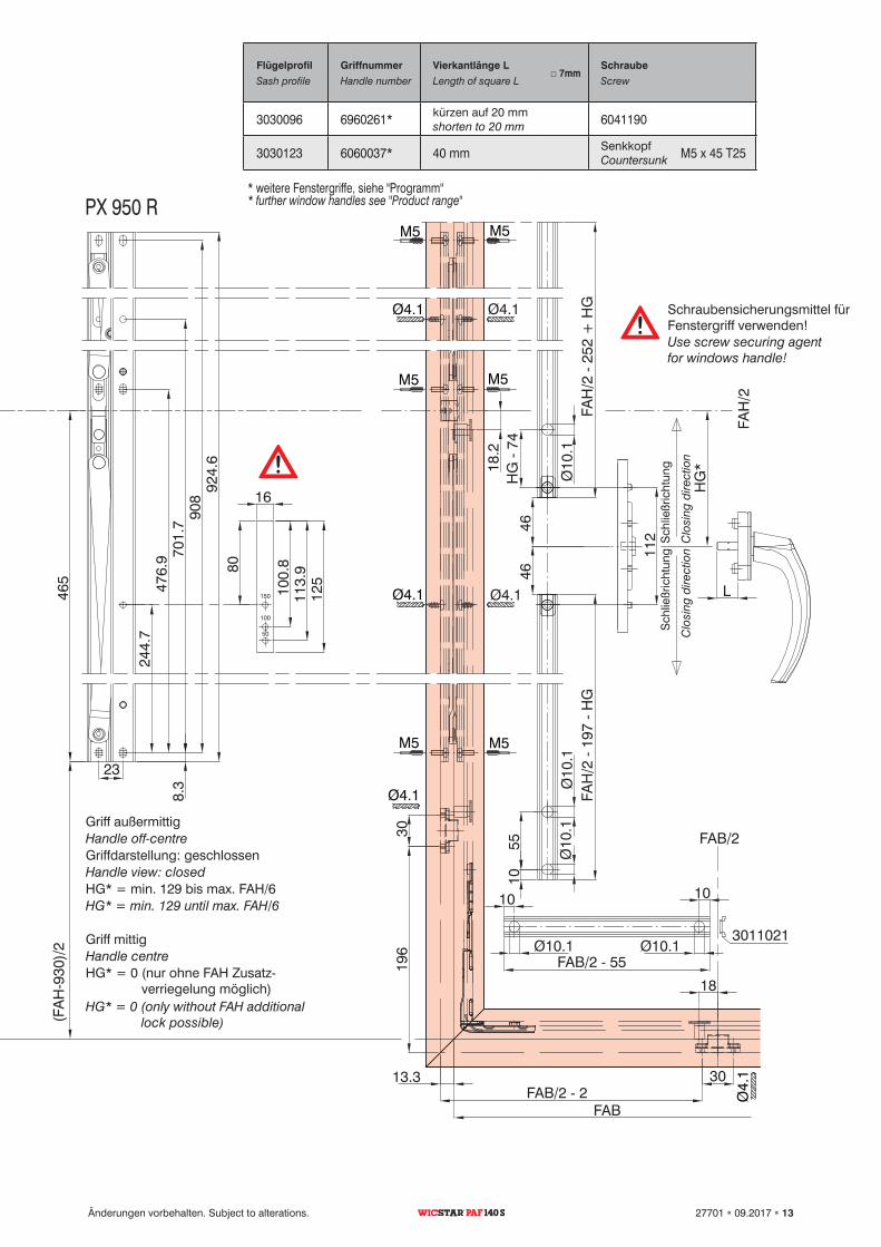
□ 7mm
3030096 6960261* 6041190
3030123 6060037* 40 mm M5 x 45 T25
Clo
sing
dire
ctio
nC
losi
ng d
irect
ion
Handle view: closed
HG* = min. 129 until max. FAH/6
Handle off-centre
Use screw securing agent for windows handle!
Handle centre
HG* = 0 (only without FAH additional lock possible)
Sash profile Handle number Length of square L Screw
shorten to 20 mm
Countersunk
* further window handles see "Product range"
Änderungen vorbehalten. Subject to alterations. 27701 09.2017 13PAF 140 S
Sch
ließr
icht
ung
Sch
ließr
icht
ung
Griffdarstellung: geschlossen
HG* = min. 129 bis max. FAH/6
Griff außermittig
Schraubensicherungsmittel für Fenstergriff verwenden!
Griff mittig
HG* = 0 (nur ohne FAH Zusatz verriegelung möglich)
Flügelprofil
Griffnummer
Vierkantlänge L
Schraube
kürzen auf 20 mm
Senkkopf
* weitere Fenstergriffe, siehe "Programm"
150
100
50
150
100
50
150
100
130
15.3
23.5
15.3
23.5
21.5
43
6
10
18
FAH
/2
270
HG
10Ø10
.1Ø
10.1
23
23
23
23
(FA
H
450)
/ 2
(FA
H
670)
/ 2
(FA
H
350)
/ 2
8.3
168
335.
7
8.3
244.
7433.
3
8.3
141.
434
740
8.6
653.
4
244.
747
6.970
1.790
8
16
Ø5.5
8010
0.8
113.
9
125
16
20
40
34
47.5
(FA
H
930)
/ 2
18
232
30
FAH
/2
215
+ H
G64
64
HG
56
1010
43
Ø10
5
1370
16
64.9
71.4
HG
*
7
Ø4.1
Ø4.1
Ø4.1
PX 350 L
PX 450 L
PX 670 L
PX 950 L
924.
6
350
450
670
16
8010
0.8
113.
9
125
199.
1
29.6
8.3
L
27
8.7
13.3
RA
H ±
1
FAH
±1
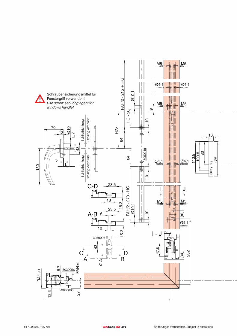
C D
I J
AB
CD
M5 M5
Ø4.1
M5 M5
M5 M5
Ø4.1
3030096
3030095
3030096
6050
019
I J
BA
Clo
sing
dire
ctio
nC
losi
ng d
irect
ion
Use screw securing agent for windows handle!
14 09.2017 27701 Änderungen vorbehalten. Subject to alterations.PAF 140 S
Sch
ließr
icht
ung
Sch
ließr
icht
ung
Schraubensicherungsmittel für Fenstergriff verwenden!
150
100
50
150
100
50
150
100
130
15.3
23.5
15.3
23.5
21.5
43
6
10
18
FAH
/2
270
HG
10Ø10
.1Ø
10.1
23
23
23
23
(FA
H
450)
/ 2
(FA
H
670)
/ 2
(FA
H
350)
/ 2
8.3
168
335.
7
8.3
244.
7433.
3
8.3
141.
434
740
8.6
653.
4
244.
747
6.970
1.790
8
16
Ø5.5
8010
0.8
113.
9
125
16
20
40
34
47.5
(FA
H
930)
/ 2
18
232
30
FAH
/2
215
+ H
G64
64
HG
56
1010
43
Ø10
5
1370
16
64.9
71.4
HG
*
7
Ø4.1
Ø4.1
Ø4.1
PX 350 L
PX 450 L
PX 670 L
PX 950 L
924.
6
350
450
670
16
8010
0.8
113.
9
125
199.
1
29.6
8.3
L
27
8.7
13.3
RA
H ±
1
FAH
±1
C D
I J
AB
CD
M5 M5
Ø4.1
M5 M5
M5 M5
Ø4.1
3030096
3030095
3030096
6050
019
I J
BA
Fixed pivot
Änderungen vorbehalten. Subject to alterations. 27701 09.2017 15PAF 140 S
Festlager
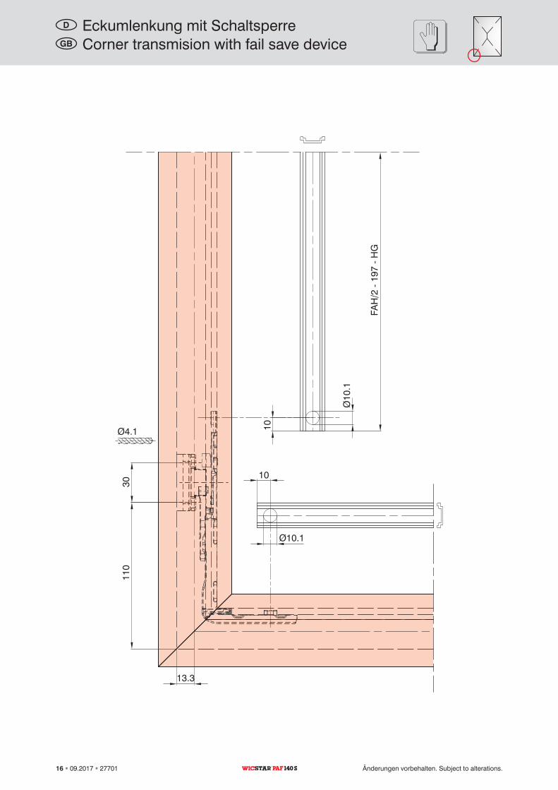
110
10
Ø10
.1
Ø10.1
10
FAH
/2
197
HG
13.3
30
Ø4.1
Corner transmision with fail save deviceGB
16 09.2017 27701 Änderungen vorbehalten. Subject to alterations.PAF 140 S
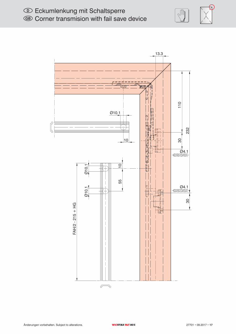
Eckumlenkung mit SchaltsperreD
110
10
Ø10
.1
Ø10.1
1055
FAH
/2
215
+ H
G
13.3
30
Ø4.1
Ø10
.1 Ø4.123
230
Corner transmision with fail save deviceGB
Änderungen vorbehalten. Subject to alterations. 27701 09.2017 17PAF 140 S
Eckumlenkung mit SchaltsperreD
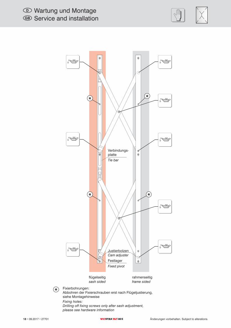
Service and installationGB
Cam adjuster
Tie bar
Fixed pivot
sash sided frame sided
Fixing holes:Drilling off fixing screws only after sash adjustment, please see hardware information
18 09.2017 27701 Änderungen vorbehalten. Subject to alterations.PAF 140 S
Wartung und MontageD
Justierbolzen
Verbindungsplatte
Festlager
flügelseitig rahmenseitig
Fixierbohrungen:Abbohren der Fixierschrauben erst nach Flügeljustierung, siehe Montagehinweise
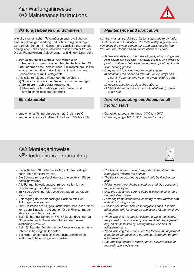
Maintenance and lubrication
As most mechanical devices, friction stays require periodic maintenance and lubrication. The friction stay in general and particulary the pivots, sliding parts and track must be kept free from dirt, debris and any obstructions at all times.
�� At time of installation: lubricate all pivot points with general light engineering oil and wipe away excess. One drop per pivot is sufficient. Lubricate the incoming pivot crank with slide bearing grease.�� Carry out the following checks every 5 years:a) Clean any dirt or debris from the friction stays and
clear any obstructions from the pivots, sliding parts and track.
b) Apply lubrication as described above.c) Check the tightness and security of all fixing screws
and rivets.
Normal operating conditions for allfriction stays
�� Operating temperature range -20°C to +60°C�� Operating range 10% to 95% relative humidity
�� The lateral parallel outward stays should be fitted with fixed pivots towards the bottom.�� The track incorporating tie plate should be fitted to the sash.�� All frame fixing boreholes should be predrilled according to the screw types.�� Only the adjustment screws holes (slotted holes) should be predrilled in sash.�� Fastering frame sided track including control retainer arm with all fastening screws.�� Loosen adjustment screws for adjusting sash. After the adjustment, drill fastening boreholes and fix the remaining screws.�� When installing the parallel outward stays in the factory, the parallelism and contact pressure should be adjusted only on the sash side by turning the top and bottom adjustment cams.�� When installing the window into the façade, the adjusment is made on the frame side by turning the top and bottom adjustment cams.�� Use opening limiters in lateral parallel outward stays for manually operated sashes.
Maintenance instructionsGB
Instructions for mountingGB
Änderungen vorbehalten. Subject to alterations. 27701 09.2017 19PAF 140 S
Wartungsarbeiten und Schmieren
Wie alle mechanischen Teile, müssen auch die Scheren einer regelmäßigen Wartung und Schmierung unterzogen werden. Die Scheren im Ganzen und speziell die Lager, die beweglichen Teile und die Schienen müssen immer frei von Dreck, Fremdkörpern, Ablagerungen und Hindernissen sein.
�� Zum Zeitpunkt des Einbaus: Schmieren aller Bolzenverbindungen mit einem leichten technischen Öl und Entfernen des Überschusses. Ein Tropfen pro Bolzen ist ausreichend. Fetten des Schereneinschlusses und Schereneinlaufs mit Gleitlagerfett.�� Alle 5 Jahre folgende Wartungen durchführen:a) Scheren von Dreck und Verschmutzungen reinigen.b) Schmieren nach obiger Anweisung.c) Überprüfen aller Befestigungsschrauben und
beweglichen Teile auf Sicherheit.
Einsatzbereich
�� empfohlener Temperaturbereich 20 °C bis +60 °C�� empfohlene relative Luftfeuchtigkeit von 10 % bis 95 %
�� Die seitlichen PAF Scheren sollten mit dem Festlager nach unten montiert werden.�� Die Schiene mit der Verbindungsplatte sollte am Flügel befestigt werden.�� Alle Rahmenbefestigungsbohrungen sollen je nach Schraubentyp vorgebohrt werden.�� Im Flügelbereich nur die Justierschrauben (Langloch) vorbohren.�� Befestigung der rahmenseitigen Schiene mit allen Befestigungsschrauben.�� Zum Einstellen des Flügels Justierschrauben lösen. Nach korrektem Einstellen, die Löcher für die Fixierschrauben abbohren und festschrauben.�� Beim Einbau der Schere im Werk Flügelandruck nur auf Flügelseite durch Drehen der oberen oder unteren Justierung einstellen.�� Beim Einbau des Fensters in die Fassade kann von innen rahmenseitig eingestellt werden. �� Bei Handbetrieb muss ein Öffnungsbegrenzer in die seitlichen Scheren eingebaut werden.
WartungshinweiseD
MontagehinweiseD
4.5
4.5
4.5
4.5
3030096
3030095
17
12.7
8.7
8.3
13.3
13.7
max
. 15
max
. 15
max
. 10
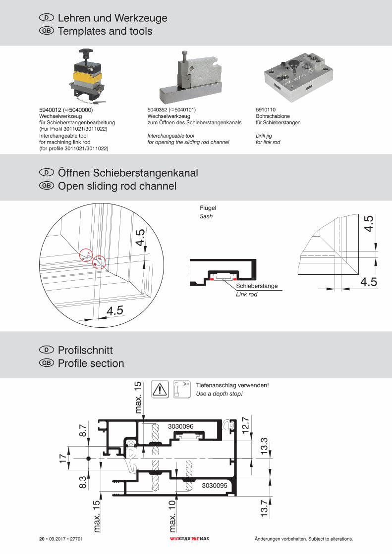
5940012 (5040000) 5040352 (5040101) 5910110
Sash
Link rod
Use a depth stop!
Templates and toolsGB
Open sliding rod channelGB
Profile sectionGB
Interchangeable tool for machining link rod (for profile 3011021/3011022)
Interchangeable tool for opening the sliding rod channel
Drill jig for link rod
20 09.2017 27701 Änderungen vorbehalten. Subject to alterations.PAF 140 S
Flügel
Schieberstange
Tiefenanschlag verwenden!
Lehren und WerkzeugeD
Öffnen SchieberstangenkanalD
ProfilschnittD
Wechselwerkzeug für Schieberstangenbearbeitung (Für Profil 3011021/3011022)
Wechselwerkzeug zum Öffnen des Schieberstangenkanals
Bohrschablone für Schieberstangen