Mauerwerk-Hochbauten im Westen der USA · aux ingenieurs, aux constructeurs et ... Sie waren "iiber...
11
Mauerwerk-Hochbauten im Westen der USA Walter L. Dickey, Consulting Structural Engineer, Masonry Institute of America, Los Ange!es, USA Kurzfassung : Das anliegende Papier gibt Architekten, Ingenieuren, Bauunternehmen und Ei- gentlimern die Grundinformation liber Entwurf und Konstruktion von mehr- stéickigen Gebauden mit bewehrten Ziegeltragwanden. Es basiert sowohl auf theoretischen Grundlagen aIs auch auf praktischen Erfahrungen im Bau solcher Gebaude im Westen, d. h. gemaB den Bestimmungen des Uniform Building Code of the International Conference of Building OHicials (einheitlicher Bau- co de der Internationalen Baubeamten- konferen z) . Die skizzierte Zusammenfassung sieht wie folgt aus: Einleitung: Konzept. Gestaltungsvorteile: Einfachheit, archi- tcktonischc Freiheit, Struktur und Ver- band, Steifigkeit, Dampfung. U mweltvorteile : Schalldammung, Feu- erwiderstand, Warmedammung und -speicherung, Wirtschaftlichkeit der Bodennutzung. Konstruktionsvorteile: Geschwindig- keit, ZweckmaBigkeit, Einfachheit. Kostenvorteile: V orkosten, niedrige Finanzierungskosten, Amortisation, niedrige Unterhaltungskosten, guter Umsatz. Gestaltung: Einflihrung, Grundlagen, Einzelheiten und Zusammenhange. Einleitung Konzept Western United States masonry high rise The enclosed presents to architects, engineers, builders and owners the basic information on the design and con- struction of multi-story reinforced masonry bearing wall buildings and is based on both theoretical principIes and field experience in construction of these buildings in the west, i. e. as under the jurisdiction of the Uniform Building Code of the International Conference of Building Officials. The outline summary is as follows: Introduction: Design and Application. Design Advantages: Simplicity, Archi- tectural Freedom, Texture and Patterns, Stiffness, Damping. Environmental Advantages: Sound, Fire, Heat, Space. Construction Advantages : Speed, Effi- ciency, Simplicity. Cost Advantages: Initial, Financing, Income, Low Maintenance, Good Turn- over. Design: Introduction, PrincipIes, De- tails and Connections. Des buildings en maçonnerie dans l'ouest des Etats-Unis Cette conférence fournit aux architects, aux ingenieurs, aux constructeurs et a ux propriétaires des informationsfonda- mentales sur la construction des buil- dings à parois portantes en maçonnerie armée, et elle est fondée aussi bien sur des principes théoriques que sur des expériences pratiques, acquises lors de la construction de ces buildings dans l'ouest des Etats-Unis, territoire relevant de la juridiction du Uniform Building Code of the International Conference of Building Officials (code général de construction de la conférence inter- nationale des fonctionnaires de la con- struction). Le résumé peut être esquissé comme suit: Introductioll: Systellle et Application. A vantage du Systeme: Silllplicité, Li- berté architecturale, Texture et Dessins, Rigidité, Alllortissement acoustique. A vantage du lllilieu: Bruit, Incendie, Telllpérature, Espace. A vantage de collstruction: Rapidité, Efficacité, Simplicité. Economie: Frais initiaux, Financement, Revenu, Entretien à bas prix, Chiffre d' affaires avantageux. Dessin: Introduction, Principes, Détail et Connection. Tragende Wande aus Mauerwerk sind eine der altesten Nut- zungsarten von dauerhaftem Baumaterial. Die frlihen Mauer- werkskonstruktionen waren aus dicken Wanden mit Natur- steinen oder Ziegeln gebaut. Sie waren "iiber den Daumen" konstruiert. Sie waren aber auch in der Erkenntnis gebaut, daB unbewehrtes Mauerwerk eine relativ niedrige Tragfahigkeit hat. Die friiheren Entwiirfe nutzten die ausgezeichnete Druck- festigkeit von Mauerwerk aus. dicke Wande im ErdgeschoB. Diese Erfordernis schreckte aus wirtschaftlichen Griinden davon ab, bewehrte Tragwande in gréiBerem Umfange fiir Hochbauten einzusetzen. Daher hat die pfahl- und Balkenbauweise beinahe bis zum beutigen Tage vorgeherrscht. Neuerdings hat jedoch der Trend zurlick zu tragenden Wan- den das alte Konzept von Architekten und Eigentlimern, tra- gendes Mauerwerk flir Hochbauten einzusetzen, wieder auf- lebenlassen. Durch Bemessung gegen Erdbebenbeanspruchung zeigt sich, daB dieses Konzept tatsachlich einen gréiBeren Wi- derstand gegenLiber Erdbebenschaden aIs die meisten anderen Materialien oder Entwiirfe haben. Die 1l10derne Bemessung Das 16stéickige 1889 in Chicago errichtet, war eines der bemerkenswertesten Beispiele der frliheren Art von Tragwanden im Hochhausbau der Vereinigten Staaten. Sein auf der Schwerkraft beruhender Entwurf erforderte 6 FuB 267
Transcript of Mauerwerk-Hochbauten im Westen der USA · aux ingenieurs, aux constructeurs et ... Sie waren "iiber...
Mauerwerk-Hochbauten im Westen der USA Walter L. Dickey, Consulting Structural Engineer, Masonry Institute of America, Los Ange!es, USA
Kurzfassung : Das anliegende Papier gibt Architekten, Ingenieuren, Bauunternehmen und Eigentlimern die Grundinformation liber Entwurf und Konstruktion von mehrstéickigen Gebauden mit bewehrten Ziegeltragwanden. Es basiert sowohl auf theoretischen Grundlagen aIs auch auf praktischen Erfahrungen im Bau solcher Gebaude im Westen, d. h. gemaB den Bestimmungen des Uniform Building Code of the International Conference of Building OHicials (einheitlicher Bauco de der Internationalen Baubeamtenkonferenz) .
Die skizzierte Zusammenfassung sieht wie folgt aus:
Einleitung: Konzept.
Gestaltungsvorteile: Einfachheit, architcktonischc Freiheit, Struktur und Verband, Steifigkeit, Dampfung.
U mweltvorteile : Schalldammung, Feuerwiderstand, Warmedammung und -speicherung, Wirtschaftlichkeit der Bodennutzung.
Konstruktionsvorteile: Geschwindigkeit, ZweckmaBigkeit, Einfachheit.
Kostenvorteile: V orkosten, niedrige Finanzierungskosten, Amortisation, niedrige Unterhaltungskosten, guter Umsatz.
Gestaltung: Einflihrung, Grundlagen, Einzelheiten und Zusammenhange.
Einleitung
Konzept
Western United States masonry high rise The enclosed presents to architects, engineers, builders and owners the basic information on the design and construction of multi-story reinforced masonry bearing wall buildings and is based on both theoretical principIes and field experience in construction of these buildings in the west, i. e. as under the jurisdiction of the Uniform Building Code of the International Conference of Building Officials.
The outline summary is as follows:
Introduction: Design and Application. Design Advantages: Simplicity, Architectural Freedom, Texture and Patterns, Stiffness, Damping.
Environmental Advantages: Sound, Fire, Heat, Space.
Construction Advantages : Speed, Efficiency, Simplicity.
Cost Advantages: Initial, Financing, Income, Low Maintenance, Good Turnover.
Design: Introduction, PrincipIes, Details and Connections.
Des buildings en maçonnerie dans l'ouest des Etats-Unis Cette conférence fournit aux architects, aux ingenieurs, aux constructeurs et a ux propriétaires des informationsfondamentales sur la construction des buildings à parois portantes en maçonnerie armée, et elle est fondée aussi bien sur des principes théoriques que sur des expériences pratiques, acquises lors de la construction de ces buildings dans l'ouest des Etats-Unis, territoire relevant de la juridiction du Uniform Building Code of the International Conference of Building Officials (code général de construction de la conférence internationale des fonctionnaires de la construction).
Le résumé peut être esquissé comme suit:
Introductioll: Systellle et Application. A vantage du Systeme: Silllplicité, Liberté architecturale, Texture et Dessins, Rigidité, Alllortissement acoustique.
A vantage du lllilieu: Bruit, Incendie, Telllpérature, Espace.
A vantage de collstruction: Rapidité, Efficacité, Simplicité.
Economie: Frais initiaux, Financement, Revenu, Entretien à bas prix, Chiffre d' affaires avantageux.
Dessin: Introduction, Principes, Détail et Connection.
Tragende Wande aus Mauerwerk sind eine der altesten Nutzungsarten von dauerhaftem Baumaterial. Die frlihen Mauerwerkskonstruktionen waren aus dicken Wanden mit Natursteinen oder Ziegeln gebaut. Sie waren "iiber den Daumen" konstruiert. Sie waren aber auch in der Erkenntnis gebaut, daB unbewehrtes Mauerwerk eine relativ niedrige Tragfahigkeit hat. Die friiheren Entwiirfe nutzten die ausgezeichnete Druckfestigkeit von Mauerwerk aus.
dicke Wande im ErdgeschoB. Diese Erfordernis schreckte aus wirtschaftlichen Griinden davon ab, bewehrte Tragwande in gréiBerem Umfange fiir Hochbauten einzusetzen. Daher hat die pfahl- und Balkenbauweise beinahe bis zum beutigen Tage vorgeherrscht. Neuerdings hat jedoch der Trend zurlick zu tragenden Wanden das alte Konzept von Architekten und Eigentlimern, tragendes Mauerwerk flir Hochbauten einzusetzen, wieder auflebenlassen. Durch Bemessung gegen Erdbebenbeanspruchung zeigt sich, daB dieses Konzept tatsachlich einen gréiBeren Widerstand gegenLiber Erdbebenschaden aIs die meisten anderen Materialien oder Entwiirfe haben. Die 1l10derne Bemessung
Das 16stéickige Manadnock-Geb~ude, 1889 in Chicago errichtet, war eines der bemerkenswertesten Beispiele der frliheren Art von Tragwanden im Hochhausbau der Vereinigten Staaten. Sein auf der Schwerkraft beruhender Entwurf erforderte 6 FuB
267
basiert auf dem Zusammenwirken von Elementen in einer Gesamtkonstruktion. So übertragen z. B. Beton- oder Stahlsteindecken die senkrechte Belastung auf Tragwande und diese weiter auf die Fundamente. Die horizontale zeitliche Belastung libemehmen die Wande ais lotrecht gespannte Platte zwischen Boden und Decke. Die Decken wirken ais horizontale Scheiben oder Trager, um die AufIagerreaktionen der Wande und die Deckenlast auf die Schwerwande zu übertragen. Die Schwerwande übertragen die horizontale Belastung auf die Fundamente. Natlirlich kommen die angenommenen Erdbebenbelastungen auf umgekehrtem Wege in das Gebaude. Das heiBt der Boden libertragt die Bewegl1ng über die Schwerwande auf die Decken und Wande. Aber flir Entwlirfe wird immer die andere Anschauung benl1tzt. Die Lastannahmen stützen sich verschiedentlich auf halbdynamische J;3etrachtungen. Auf diese Weise werden gleichwertige Entwurfsgrundlagen flir die Erdbebenwiderstandsfahigkeit erzielt. Das beschriebene Modell eignet sich al1ch flir Belastung durch Wind.
Diese modeme Verwendung des bewehrten Mauerwerks ist in den neuen Entwurfsbestimmungen berücksichtigt. Dort wird anerkannt, daB Tragwande hohere Beanspruchungen al1shalten, und es wird eine solche hohere Beanspruchung zugelassen. Gewisse Werte in der neuen Code sind mehr aIs doppelt so hoch, wie sie in der Vergangenheit zugelassen waren.
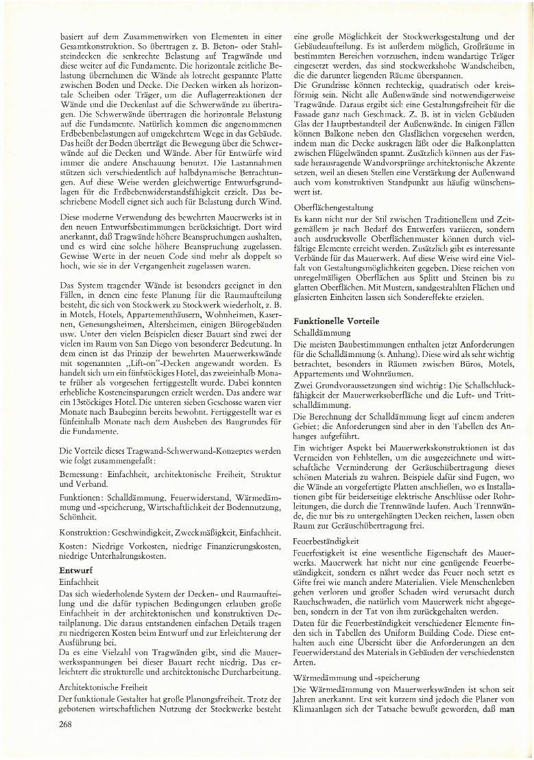
Das System tragender Wande ist besonders geeignet in den FalIen, in denen eine feste Planung flir die Raumaufteilung besteht, die sich von Stockwerk zu Stockwerk wiederholt, z. B. in Motels, Hotels, Appartementhausem, Wohnheimen, Kasernen, Genesungsheimen, Altersheimen, einigen Bürogebauden usw. Unter den vielen Beispielen dieser Bauart sind zwei der vielen im Raum von San Diego von besonderer Bedeutung. In dem einen ist das Prinzip der bewehrten Mauerwerkswande mit sogenannten "Lift-on"-Decken angewandt worden. Es handelt sich um ein fünfstockiges Hotel, das zweieinhalb Monate früher ais vorgesehen fertiggestelIt wurde. Dabei konnten erhebliche Kosteneinsparungen erzielt werden. Das andere war ein 13stockiges Hotel. Die unteren sieben Geschosse waren vier Monate nach Baubeginn bereits bewohnt. FertiggestelIt war es flinfeinhalb Monate nach dem Ausheben des Baugrundes für die Fundamente.
Die Vorteile dieses Tragwand-Schwerwand-Konzeptes werden wie folgt zusammengefaBt:
Bemessung: Einfachheit, architektonische Freiheit, Struktur und Verband.
Funktionen: SchalIdammung, Feuerwiderstand, Warmedammung und -speicherung, Wirtschaftlichkeit der Bodennutzung, Schonheit.
Konstruktion: Geschwindigkeit, ZweckmaBigkeit, Einfachheit.
Kosten: Niedrige Vorkosten, niedrige Finanzierungskosten, niedrige Unterhaltungskosten.
Entwurf Einfachheit
Das sich wiederholende System der Decken- und Raumaufteilung und die dafür typischen Bedingl1ngen erlauben groBe Einfachheit in der architektonischen und konstruktiven Detailplanung. Die daraus entstandenen einfachen Details tragen zu niedrigeren Kosten beim Entwurf und zur Erleichterung der Ausflihrung bei. Da es eine Vielzahl von Tragwanden gibt, sind die Mauerwerksspannungen bei dieser Bauart recht niedrig. Das erleichtert die strukturelIe und architektonische Durcharbeitung.
Architektonische Freiheit
Der funktionale Gestaltet hat groBe Planungsfreiheit. Trotz der gebotenen wirtschaftlichen Nutzung der Stockwerke besteht
268
eine groBe Moglichkeit der Stockwerksgestaltung und der Gebaudeaufteill1ng. Es ist auBerdem moglich, GroBraume in bestimmten Bereichen vorzusehen, indem wandartige Trager eingesetzt werden, das sind stockwerkshohe Wandscheiben, die die darunter liegenden Ral1me überspannen. Die Grundrisse konnen rechteckig, quadratisch oder kreisformig sein. Nicht alie AuBenwande sind notwendigerweise Tragwande. Daral1s ergibt sich eine Gestaltungsfreiheit für die Fassade ganz nach Geschmack. Z. B. ist in vielen Gebauden Glas der Hauptbestandteil der AuBenwande. In einigen FaIlen konnen BaIkone neben den GlasfIachen vorgesehen werden, indem man die Decke auskragen laBt oder die BaIkonplatten zwischen Flügelwanden spannt. Zusatzlich konnen aus der Fassade herausragende Wandvorsprünge architektonische Akzente setzen, weil an diesen Stellen eine Verstarkung der Al1Benwand auch vom konstruktiven Standpl1nkt al1S haufig wünschenswert isto
o berfIachengestaltung
Es kalill nicht nur der Sti! zwischen Traditionellem und ZeitgemaBem je nach Bedarf des Entwerfers variieren, sondem auch ausdrucksvoIle OberfIachenmuster konnen durch vielfaltige Ele mente erreicht werden. Zusatzlich gibt es interessante Verbande für das Mauerwerk. Auf diese Weise wird eine Vielfalt von Gestaltungsmoglichkeiten gegeben. Diese reichen von unregelmaBigen Oberflachen aus Splitt und Steinen bis Zl1 glatten OberfIachen. Mit Mustem, sandgestrahlten Flachen l1nd glasierten Einheiten lassen sich Sondereffekte erzielen.
Funktionelle Vorteile SchaIldammung
Die meisten Bal1bestimml1ngen enthalten jetzt Anforderungen für die SchalIdammung (s. Anhang). Diese wird ais sehr wichtig betrachtet, besonders in Raumen zwischen Büros, Motels, Appartements und Wohnraul11en.
Zwei Grundvoraussetzl1ngen sind wichtig: Die SchalIschluckfahigkeit der Mauerwerksoberflache l1nd die Ll1ft- und TrittschalIdammung.
Die Berechnung der SchaIldal11mung liegt al1f einem anderen Gebiet; die Anforderungen sind aber in den Tabellen des Anhanges aufgeführt.
Ein wichtiger Aspekt bei Mal1erwerkskonstruktionen ist das Vermeiden von FehlsteIlen, um die ausgezeichnete l1nd wirtschaftliche Verminderung der Gerauschübertragung dieses schonen MateriaIs zu wahren. Beispiele dafür sind Fugen, wo die Wande an vorgefertigte Platten anschlieBen, wo es InstaIlationen gibt für beiderseitige elektrische Anschlüsse oder Rohrleitl1ngen, die durch die Trennwande laufen. Auch Trennwande, die nur bis zu untergehangten Decken reichen, lassen oben Raum zur Geral1schübertragl1ng frei.
Feuerbestandigkeit
Feuerfestigkeit ist eine wesentliche Eigenschaft des Mauerwerks. Mauerwerk hat nicht nur eine genligende Feuerbestandigkeit, sondem es nahrt weder das Fel1er noch setzt es Cifte frei wie manch andere Materialien. Vi ele Menschenleben gehen verloren und groBer Schaden wird verursacht dnrch Rauchschwaden, die natürlich vom Mauerwerk nicht abgegeben, sondem in der Tat von ihm zurlickgehalten werden.
Daten für die Feuerbestandigkeit verschiedener Ele mente finden sich in TabeIlen des Uniform Building Code. Diese enthalten auch eine Übersicht über die Anforderungen an den Feuerwiderstand des Materiais in Gebauden der verschiedensten Arten.
Warmedammung und -speicherung
Die Warmedammung von Mauerwerkswanden ist schon seit Jahren anerkannt. Erst seit kurzem sind jedoch die Planer von Klimaanlagen sich der Tatsache bewul3t geworden, daB mau
-an die Klimaausrüstung aufgrund der einfachen konventione!len Berechnungen mit U-Faktoren hohere Anforderungen stellt, aIs es das Gebaude tatsachlich verlangt. Dies unterstreicht die thermische Tragheit, d. h. den Schwungradeffekt einer groBen Warmespeicherung in soliden Mauerwerkswanden. Solche Wande wirken aIs Reservoir und gleichen die groBen Schwankungen der Oberflachentemperatur aus. Dadurch vermindern sich Umfang und Kosten der notwendigen Klimaanlagen sowie die Unterhaltungskosten. Diese Tatsache wird von US-Bundesbehorden für Wohnungsbau und Stadteplanung wie auch von den US-Staatsbehorden für Wohnungsbau aIs wichtig angesehen. Die Anerkennung der hoheren Leistung von Mauerwerk schIagt sich in den Tabellen nieder, die zeigen, daB Mauerwerkswande geringere Warmewiderstands-Koeffizienten verlangen aIs andere oberflachenisolierte wande.
Wirtschaftlichkeit der Bodennutzung
Da vie!geschossige Gebaude weniger Grundstücksflache in Anspruch nehmen, braucht die vorhandene Oberflache des Grundstücks nur geringfügig verandert zu werden. Das bedeutet, daB das Gebaude weniger die Ókologie und die U mwe!t stort. Es hat kaum EinfluB auf die Drainage in diesem Gebiet, auf die Landschaftsgestaltung usw.
Schonheit
Schonheit und Einfachheit haben seit langem das sauber gestaItete Mauerwerk für den Bau menschlicher Behausungen attraktiv gemacht. Mauerwerk laBt sich auf gefallige Art in die Landschaft einfügen oder auch majestatisch daraus abheben.
Bauvorteile Geschwindigkeit
Im Bauwesen kostet Zeit Geld. Da man mit gemauerten tragenden Wanden rasch und wirtschaftlich Gebaude errichten kann, spart man Zeit und Geld.
Ein 6- bis 10stockiges Gebaude, ein groBes Bauvorhaben also, kann Ieicht in 6 bis 8 Monaten fertiggestellt werden. Das heiBt, daR die Gemeinkosten und die Bauaufsichtskosten des Unternehmers niedriger sind aIs beim selben Projekt nach einem anderen Verfahren. Dem Bauherrn, der sein Geld investiert hat, wird das Objekt früher übergeben. Dies vermindert nicht nur seine Kredit- und ZinsIasten, sondern es bringt ihm eher Einnahmen aus dem Gebaude. Ein Verfahrensvergleich findet sich in der Anlage.
Arbeitseffizienz
Dieses System bringt hohe ArbeitsIeistung, und sie nimmt zu bei Fortschreiten des Baus in die hoheren Stockwerke. Man bedient sich der Methoden einer Massenanfertigung anstatt der herkommlichen Arbeitsweise. Dieses kontinuierliche Arbeitsverfahren vermeidet Kosten für Unvorhergesehenes sowie für groBe Gerüste, die bei diesem Verfahren überflüssig sind. Es ist von V orteil, daB eine Handwerkergruppe schnell der anderen folgen kann. Z. B. kann das Vorfertigen der Decken gleichzeitig mit dem Ausschachten und den Fundierungsarbeiten geschehen. Man kann mit wenigen Handwerkern auskommen. Dies erleichtert den AbIauf der Arbeiten, weil weniger Koordination notwendig isto Der Maurer setzt die Trennwande und versetzt gleichzeitig die FertigteiIe. Wenn die Wande erstellt sind, konnen die Decken sofort aufgelegt werden. Die anderen Handwerker konnen sofort in einem Eertiggestellten Raum arbeiten. Diese Folge von sich wiederholenden Arbeiten bis zur Baufertigstellung vermindert Verwirrung, kostspielige Fehler und Verzogerungen.
Einfachheit
Die Einfachheit der Details und der gesamten Konstruktion vergroBert all die anderen V orteile.
Kostenvorteile Niedrige V orkosten Die Bauweise mit tragenden Mauerwerkswanden ist im Vergleich zu anderen wesentlich billiger. Der Raum wird zweckmaBiger ausgenutzt, denn es gibt keine SauIen und Balken, die im Raume stehen und deshaIb AufteiIungsprobleme verursachen. Die kürzeren Spannweiten erlauben dünnere Decken. Dies wiederum führt zu einer geringeren Gesamthohe mehrstockiger Gebaude. In einem konkreten Fall konnte die Gesamthohe etwa um eine Stockwerkshohe vermindert werden durch die Verwendung von Fertigplatten. Auf diese Weise lieR sich in dem geplanten umbauten Raum ein zusatzliches GeschoB gewinnen.
Da die Bauvorkosten niedriger Iiegen aIs bei anderen Bauverfahren, bezieht der Bauherr eine groBere Rendite aus seiner Investition. Seine Investition ist niedriger, daher die Gewinnspanne hoher.
Finanzierungskosten Das Geld des Bauherrn ist für eine kürzere Zeit gebunden. Er spart die Zinsen, die anderenfalls für Baukredite auszugeben waren. Sein Geld kann eher in anderen Projekten investiert werden. Die Finanzierungskosten sind niedriger, weil der Baukredit kIeiner isto
Niedrige Unterhaltungskosten Diese Bauart ist eine gute Investition, weil sie geringe Unterhaltungskosten verlangt. Dies wiederum führt zu einer groBeren Gewinnspanne. NaturgemaB sind auch die Versicherungspramien wesentlich niedriger für dieses dauerhaftere, feuerbestandige Material aIs bei anderen Baustoffen. Diese Pramienersparnis vermindert Kosten, die sonst die Gewinnspanne, den Unterschied zwischen Einnahmen und Ausgaben, verkleinern würden.
Da das Gebaude vollig feuersicher ist, werden vie!e Eigentümer eine Versicherung abschlieRen, die nur den brennbaren Inhalt der Zimmer deckt. So verl11indern sich die Betriebskosten erheblich. Nicht nur die obengenannten Versicherungskosten sind relativ niedriger; die dauerhafte Tragwand garantiert auch ein Minil11um an Unterhaltungsproblel11en und -kosten wahrend der ganzen Lebensdauer des Gebaudes.
Technischer Entwurf Dieser Bericht handelt von der sogenannten Schachtelbauweise ("box-system"), so wie sie in den Grundsatzen für die Bel11essung auf Seitenkrafte il11 Uniforl11 Building Code UI11-
und beschrieben isto Es handelt sich um ein Systel11 von Tragwanden, die gleichzeitig aIs Schwerwande (Windscheiben) dienen. Es ist eine der wirksal11sten Arten, bewehrtes Mauerwerk zu verwenden. Das ideale System nutzt die Vielzahl der Wande und die kurzen Deckenspannweiten aus und erreicht eine ausgezeichnete Lastverteilung. Dies verl11indert die Beanspruchung des Materiais und ist ein sicheres, geSlmdes und solides Bauverfahren.
Das derzeitige Bel11essungsverfahren ist beschrieben im Handbuch für Mauerwerksentwürfe, herausgegeben vom USInstitut für Mauerwerk (Masonry Design Manual, auszugsweise im Anhang wiedergegeben).
GemaB Uniform Co de wird bei der Schachtelbauweise (boxsystem) ais K-Faktor 1,33 für Seitenkrafte angenommen. Dies ist mehr, aIs bei anderen Bauwerken verlangt wird. Es wird davon ausgegangen, daB steife Bauwerke Kraften oder StoBen infolge von Querschwingungen starker ausgesetzt sind. Diese groBere Steifigkeit wird aber von einer so groBen Tragfahigkeitsreserve begIeitet, daB die Spannungen im Mauerwerk trotz der scharferen Lastannahme auBerst niedrig bleiben. Dies führt zu einer sehr hohen Sicherheit im fertigen Bauwerk.
269
Steifigkeit Die Bemessungsgrundsatze berücksichtigen die Tatsache, daB die Reaktion von Gebauden auf Erdbeben beeinfluBt wird von der Eigenschwingung des Gebaudes. In genaueren dynamischen Analysen stellt man aber fest, daB auch die Einwirkungen auf das Gebaude geringer waren, faUs die Eigenfrequenz des Gebaudes sehr viel hoher lage aIs die maBgebende Erdbebenfrequenz. Die Baubestimmungen berücksichtigen diesen Faktor bei der Bemessung auf Erdbebenbelastung nicht. Es ware also moglich, daB steife Bauwerke im Bereich der aussteifenden Scherwande einer viel niedrigeren tatsachlichen Belastung ausgesetzt waren, aIs angenommen. In diesem FaUe gabe es eine zusatzliche Sicherheit bei den mit Scheiben ausgesteiften Bauwerken. Dies wird mehr lmd mehr von den Konstrukteuren anerkannt aufgrund der guten Erfahrungen mit solchen Gebauden bei Erdbeben. Zudem richten die Erschütterungen in ausgesteiften Bauten viel weniger Schaden an, weil die Verformungen gering sind. Das bedeutet in physikalischer Hinsicht, daB es in ausgesteiften Bauten keine sogenannten "nicht strukturelIen Schaden" ("nonstructural" damage) gibt, wie man sie sie sonst bei flexiblen Bauten findet. Die flexiblen Bauten haben auch dann, wenn sie eine vergleichbare Festigkeit aufweisen, eine groBere Durchbiegung. Diese beschadigt Glas, Putz, Treppen, Einrichtungen und andere kostbare Dinge. Solch "nicht struktureller Schaden" dürfte teurer zu stehen kommen aIs das Bauwerk selbst.
Die Vorteile der Steifigkeit wurden eindrucksvolI bewiesen durch den Widerstand der durch Scherwande ausgesteiften Gebaude des Sepulveda Veterans Hospital im Erdbebengebiet von San Fernando. Es war das einzige von fünf Krankenhausern in dem Gebiet, das stehenblieb, und es hatte keinen Gebaudeschaden erlitten. Der minimale "nicht strukturelIe Schaden" beschrankte sich auf Unterbrechung der Leitungen zwischen den nebeneinanderliegenden Gebauden. Einige Schaden traten bei den mechanischen Einrichtungen auf, die nicht für die Anfnahme von Seitenkraften konstruiert waren.
Dampfung
Die Dampfung in einer Gebaudekonstruktion ist deren Fahigkeit, die Schwingungsamplitude durch innere Reibung oder Energieverzehrung zu vermindern. Überschreiten die Durchbiegungen den elastischen Bereich, so wird die Energie-Absorption zu einem Energieverlust oder zu einem Hystereseverlust.
DaB die meisten der bewehrten Mauerwerksbauten das Erdbeben in Alaska 1964 ohne Schaden überstanden haben, liegt vermutlich an der hohen Energieverzehrung. Diese tritt dann ein, wenn die Elastizitatsgrenze überschritten isto Die einzigen Schaden am Mauerwerk wurden verursacht durch unsachgemaBe Verankerung oder weil es nicht bewehrt war.
Eine Untersuchung ergab, daB ungefahr 80% der bewehrten Mauerwerksbauten das Alaska-Erdbeben volIig unbeschadigt überstanden haben. Sekundarschaden an der Einrichtung waren in ausgesteiften Bauwerken viel kleiner aIs in nicht ausgesteiften Rahmenkonstruktionen.
Einzellleiten über die Verbindungen
Die Verbindung der Elemente im Hochbausystem ist wichtig, weil sie die einzelnen Teile zusammenhalt und bewirkt, daB sie ins Gesamtsystem eingegliedert werden. Um das Zusammenwirken eines groBen Systems von Elementen volI ausnutzen zu konnen, müssen die Verbindungen genau beachtet werden. Eine Scheibenwirkung der Decken- oder Wandelemente tritt nur dann in Funktion, wenn die Randglieder einen Ringanker erhalten; dieser muB ins Deckensystem eingebettet werden. Die haufigsten Verbindungen werden durch SchweiBen oder FugenvergieBen hergestellt.
270
Bei SchweiBverbindungen muB man einwandfreie SchweiBverfahren und KontrolIen anwenden. Die Verbindung muB im Detail so ausgebildet sein, daB kein Sprodbruch auftritt. Die VerguBfugen müssen das FlieBen der eingebetteten Stahleinlagen ermoglichen. Eine besonders wichtige Verbindung ist die zwischen Wand und Fundienmg. Die relative Steifigkeit der Fundierung spielt dabei eine wesentliche RolIe. Die Verbindung muB so ausgeführt werden, daB die Verankerung der Wand die fUr die Berechnung angenommene Kraft aufnehmen kann.
Einen Überblick über die einzelnen Schritte fUr den Entwurf eines bewehrten Mauerwerksbaues gibt der im Anhang wiedergegebene Auszug aus dem "Masonry Design Manual". Die Berechnung der vertikalen Belastung ist natürlich einfach und wird nach herkommlichen Verfahren durchgeführt. Die Verfahren zur Berechnung der Seitenkrafte werden im "Uniform Building Code" beschrieben. Sie sind in del11 AUSZllg zusammengefaBt.
Ãhnliche Verfahren werden in verschiedenen Veroffentlichungen über die Bel11essung von Schwerwanden aus Ziegel- und Betonsteinmauerwerk beschrieben.
Auszüge aus amerikanischen Bemessungsrichtlinien und erlautemde DarstelIungen. (Von einer Übersetzung ins Deutsche wurde wegen des spezielIen Zuschnittes auf amerikanische Verhaltnisse abgesehen.)
Western United States Masonry High Rise
Introduction Concept. The concept of l11asonry bearing walIs is one of man' s oldest use of permanent building materiaIs. The early initial masonry construction utilized thick walIs built of natural stone or of clay brick and was constructed on the basis of " rule of thumb". It was also based on recognition of the fact that unreinforced masonry is relativcly poor in tension value. The earlier designs were based on utilization of the excelIent compression strength of masonry.
The 16 story Manadnock building, built in Chicago in 1889, was one of the most notable examples of the early type of masonry bearing walI high ris e construction in the United States. Its gravity type design required 6' thick walIs at the ground level and this requirement economicaUy discouraged greater use of unreinforced l11asonry bearing walIs for talI buildings, and then the post and beam principIe of construction dominated until relatively recently. Howcver, a recent trend back to the use of bearing walIs has revitalized the concept of use of load bearing l11asonry for talI buildings by designers and owners. By recognizing the probIems of earthquake hazards and providing proper design to resist those, this concept has now been shown to have greater resistance to earthquake damage and distress than most other materiaIs or schemes. The modem philosophy of design is based on combining elements into an integral structural system. Thi scheme, for example, would be concrete or masonry floor. q.rrying verticalloads to bearing walIs which would carry the loads to foundations. The lateralload resistance of waUs would be in span from fIoor to ceiling. The floors and ceilings span as horizontal diaphragms or girders to carry the walI reactions and the floor load weight to the shear walIs. The shear walb transmit the lateral load to the foundations. af COlme it is recognized that the assumed seis mie loads actualIy come into the building in the opposite direction, that is, the ground il11parts the motion which moves the shear walIs which move~ the flonrs which moves walIs, but for purposes of design tht other philosphy is used.
The magnitude of those assumed loads is variable based on semidynamic modifications of judgement to provide equitable
p:z
design considerations for earthquake resistance. However the pattem or scheme described would also function for wind loading.
This newer use of engineered reinforced masonry is benefited by recent design code changes which recognize the higher stresses possible with masonry bearing wal1s and provides for use of those higher stresses. Certain values under the new code are more than double the f' mor ulti mate compression strength, vallles permitted in the pasto
The brick bearing wall system is particlllar1y suited to structures in which there is a fixed pattem of area separations repeated from Hoor to Hoor sllch as in motels, hotels, apartments, dormitories, barracks, convalescent homes, retirement homes, some office bllildings and 50 forth. Among the many examples of this type of construction two of the many in the San Diego area are rather striking. One used the principIe of reinforced masonry bearing walls with "lift-on" slabs and was a 5 story hotel completed 2% months ahead of schedule which represented a very substantial saving in overall cost. The other was a 13 story hotel which was occllpied in the lower 7 Hoors within 4 months after start of construction and was completed for a total occupancy 111 5% months from start of foundation excavation.
The advantages of this masonry bearing wall-shear wall concept are su mmarized in olltline form as follows:
Design: Simplicity, Architectural Freedom, Texture and Pattem.
Functional: SOllnd Control, Fire Resistance, Thermal Intertia and Resistance, Economy of Grol1nd Use, Beauty.
Construction: Speed, Efficiency, Simple.
Cost: Low initial cost, Low financing cost, Low maintenance cost.
Design Simplicity
The repetitive Hoor system and typical conditions permit great simplicity of architectural and structural design detailing and layout. The consequent simple details are conducive to lower cost in design and ease of execl1tion.
Since there is a l11ultiplicity of bearing walls carrying the load the stresses in this type of structure are quite low and this low level of stress makes for ease of structural detailing and architectural detailing.
Architectllral Freedo m
The fllnctional designer has a great deal of freedom in his planning. While there is an economy in use of Hoor to Hoor repetition of interior space areas, there is great potential in varying Hoor plan arrangements and in building configuration. Also it is possible to provide for clear spans in certain areas by ~lse of the bearing walls as wall beams, that is, story high beams that span the areas beneath.
The plans may be rectanglllar, square or circular in plano Also unique layouts such as those shown in the accompanying sketch may be utilized economically and effectively. The exterior walls are not necessarily all load bearing therefore freedom of exterior treatment is possible to a pleasing degree. For example, in many buildings glass is a major part of the exterior wall. In some cases balconies can be provided beyond the glass area by cantilevering the Hoor or by spanning between the masonry walls which extend as fins or wings beyond the face of the structure. In addition certa in architectural emphasis can be given to the ends of walls that project from the face because at that point strengthening of the wall is frequently desirable also from a structural standpoint.
S urface versatility
Not only can the style vary through the range of traditional to contemporary as the designer needs, expressive textures of surfaces can be provided by a great variety of elements. In addition there are interesting pattems and bonds in which the masonry may be laid in order to provide a wide range of types of exposure. These may vary from rugged split face, rock faced or irregular types to smooth surfaces and precise planes in large and small character. Pattems, sandblasting and glazed units are available to provide many special effects.
Functional Advantages
Sound control
Most building codes now conta in reqllirements for sound control such as those indicated by the tables and data accompanying. Sound control is recognized as being very important, particular1y in spaces between offices, motelunits, apartments and living space.
There are two basic items of il11portance, one is the sound absorbing quality of masonry surfaces and the other is the resistance to air borne sound transmitted from one area to another, as wel1 as impact sounds that are transl11itted from one level to another, as through floors.
The detailed design of the sound control is in other areas hut the requirel11ents are indicated by the tables following.
The important aspect in masonry construction in order to l11aintain the excellent and econol11ical rednction of sound transmission is to provide care in design to eliminate leaks which redllce the effectiveness of this fine material. Examples of such leaks are where joints occur, as where walls meet precast slabs, where there is installations of back to back electrical outlets, or piping and ducts that extend through partitions. Also low partitions which may extend only to sllspended ceilings leaving space above for passage of sonnd.
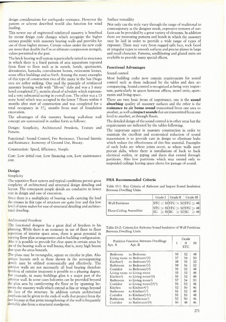
FHA Recommended Cri teria
Table 10.1: Key Cri teria of Airborne and Impact Sound Insulation Between Dwelling Units.
I Grade I I Grade II I Grade III
Wall Partitions STC :s;; 55 jSTC ::2: 52 STC ::2: 48
Floor-Ceiling Assemblies STC ::2: 55
I
STC::2: 52 STC ::2: 48 lIC ::2: 55 IIC ::2: 52 IIC ::2: 48
Table 10-2: Criteria for Airborne Sound Insulation of Wall Partitions Between Dwelling Units.
Partition Function Between Dwellings I Grade
Apt. A Apt. B
I I I II I III
STC
Bedroom to Bedroom 55 52 48 Living room to BedroomI)2) 57 54 50 Kitchen3) to BedroomI)2) 58 55 52 Bathroom to Bedroom I)2) 59 56 52 Corrido r to Bedroom2)4) 55 52 48 Living room to Living room 55 52 48 Kitchen3) to Li ving roomI )2) 55 52 48 Bathroom to Li ving room 1) 57 54 50 Corridor to Living room2)4) 5) 55 52 48 Kitchen to Kitchen 6) 7) 52 50 I 46 I Bathroom to KitchenI) 7) 55 52 48 Corridor to Kitchen2) 4) 5) 55 52 48 Bathroom to Bathroom7) 52 50 46 Corridor to Bathroom2)4) 50 48 46
271
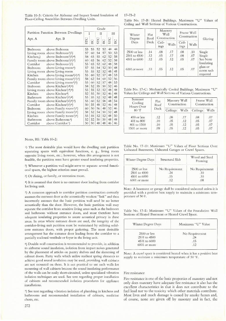
Table 10-3: Criteriafor Airborne and Impact Sound Insulation of Floor-Ceiling Assemblies Between Dwelling Units.
Grade Partition Function Between Dwellings I II III
Apt. A Apt. B ulu u lu ulu f-< ...... f-< ...... 1;; ::::; C/l ...... C/l ......
Bedroom above Bedroom 55 55 52 52 4R 148 Living room above Bedrooml)2) 57 60 54 57 50 53 Kitchen3) above Bedrooml)2)4) 58 65 55 62 52 58 Family room above Bedrooml)2)5) 60 65 56 62 52 58 Corridor above Bedrooml)2) 55 65 52 62 48 58 Bedroom above Living room6) 57 55 54 52 50 48 Living room above Living room 55 55 52 52 48 48 Kitchen above Living rooml)2)4) 55 60 52 57 48 53 Family room above Living room l)2) 5) 58 62 54 60 52 56 Corridor above Living rooml)2) 55 60 52 57 48 53 Bedroom above Kitchenl)4)6) 58 52 55 50 52 46 Living room above Kirchen l)4)6) 55 55 52 52 48 48 Kitchen above Kitchen4) 52 55 50 52 46 48 Bathroom above Kitchen1)2)4) 55 55 52 52 48 48 Family room above Kitchen l)2)4)5) 55 60 52 58 48 54 Corrido r above Kitchen1)2)4) 50 55 48 52 46 48 Bedroom above Family room l)5) 60 50 56 48 52 46 Living room above Family rooml)6) 58 52 54 50 52 48 Kitchen above Family rooml)6) 55 55 52 52 48 50 Bathroom above Bathroom4) 52 52 50 50 48 48 Corridor above Corridor7) 50 50 48 48 46 46
Notes, RE: Table 10-2 :
I) The most desirable plan would have the dwelling unit partition separating spaces with equivalent functi ons, e. g., living room opposite living room, etc.; however, when this arrangement is not feasible, the partition l11ust have greater sound insulating properties.
2) Whenever a partition wallmight serve to separate several functional spaces, the highest criterion mnst prevail.
3) Or dining, or famil y, or recreation room.
4) It is assumed that there is no entrance door leading frol11 corridor lot living unit.
S) A coml11on approach to corri dor partition construction correctly assumes the entrance door as the acoustically weakest " link" and then incorrectly assumes that the hasic partition wall need be no better acoustically than the door. However, the basic partition wall may separate the corridor Erom sensitive living areas such as the bedroom and bathrool11. without entrance doors, and must therefore have adequate insulating properties to assure acoustical privacy in these areas. In areas where entrance doors are used, the integrity of the corridor-li ving unit partition must be maintained by utilizing solidcore entrance doors, w ith proper gasketing. The most desirable arrangement has the entrance door leading from the corrido r to a partially enclosed vestibule or foyer in the living unit.
6) DOllble-wall construction is recommended to provide, in addition to airborne sOllnd inslllation, isolation from. impact noises generated by the placement of articles on pantry shelves and the slamming of cabinet doors. Party walls which utili ze resilient spring elements to achieve good sound inslllation may be used, providing wall cabinets are not mOllnted on them. It is not practical to use sllch walls for mounting of wall cabinets beca use the sound insulating performance of the walls can be easily short-circuited, unless specialized vibration isolation techniqlles are llsed. See text regarding proper installation of cabinets and recol11mended isolation procedures for appliance installations.
7) See text regarding vibration isolation of plumbing in kitchens and bathrooms and recommended installation of cabinets, medicine chests, etc.
272
17-73-2
Table No . 17-B: Heated Bllildings. Maximum "U" Values of Ceiling and Wall SectiollS of Various Constructions.
[ Flat Masonry
I Frame Wall
Winter Wall Construction
Degree I Roof Construction Glazing
Days Deck Ceil-I Walls I
Ceil-I Walls I ings lI1gs
2500 or less .14 .08 .17 .08 .10 Single 2501 to 4500 .12 .05 .17 .08 .07 Single 4501 to 6000 .12 .05 .12 .05 .07 See Note
lnsubting
6001 or more .10 .05 .12
I .05 .07
glass or storm sash
I required
Table No. 17-C : Mechanically Coolcd Buildings. Maximlll11 "u" Vallles for Ceilings and Wall Sections of Various Constructions.
Summer Flat Masonry Wall I Frame Wall
Cooling Roof Construction I Construction
Hours Over Deck --
80 DF I Ceilings I Walls Ceilings W alls
400 or less .12 I .08 I .17 I .08 I .07 401 to 800 .10 .05 .12 I .05 .07
801 to 1500 .10 .05 .12
[
.05 .07 1501 or 1110re .09 .05 .12 .05 .07
Table No. 17-D: M axil11l1l11 "u" Vallles of Floor Sections Over Unheated Basements, Unheated Garages or Crawl Spaces.
Winter Degree Days Structllral Slab I
W ood and Steel Framing
I 2500 or less No Regllirement I No Regllirement
2501 to 4500 .24 .10 4501 to 6000 .15
I .10
6001 or more .12 .08
N ote: A basement or garage shall be considered lInheated lIn\ess it is provided with a positive heat sllpply to maintain a minimum tempera ture of 50 F.
Table No. 17-E : Maximlllll "U" Valllcs of the FOllndation Wall Sections of Hea~ed Baselllent or Heated Crawl Space.
Winter Degree Days
2500 or less 2501 to 4500 4501 to 6000 6001 or more
M axim1ll1l "U" Vallle
No Reglliremcnt .24 .15 .12
N ote: A crawl space is considered heated when it has a positive heat sllpply to maintain a minimum temperaturc of 50 DF.
Fire resistance
Fire resistance is one of the basic properties of masonry and not only does masonry have adequate fire resistance it also has the excellent characteristics in that it does not contribute to the fuelload nor to the toxicity which other materiaIs contribute. Most Iives and I11uch damage is caused by smoke fumes and, of course, none are given off by masonry and in fact, the
r masonry may conta in such fumes. The actual values of various eIements for fire resistance are indicated in the enclosed tables which are excerpts from the Uniform Building Code. These tables include also a table showing the need for fire rating of materiaIs in buildings of nrious areas.
Thermal inertia and resistance
The heat transmission resistance of masonry walls has been recognized for years however, recently designers of air conditioning systems have realized that conditioning equipment requirements determined by simpIe conventional calculations based on simple U factors gave higher requirements than the compIeted building demanded in practice. This emphasized the phenomena of thermal inertia that is, the fly wheeI eHect of high heat storage capacity in solid masonry walls. They act as reservoirs to leveI out the wide Huctuations of surface temperature. This reservoir type phenomena reduces the size and cost of cooling and heating equipment necessary, as well as maintenance cost.
This Iatter factor of power is recognized as important by the U .S. government agencies of Housing and Urban Development and Federal Housing Agency. Their recognition of this superior performance of masonry is shown by the tables of coeHicient which indicate that masonry walls require lesser heat flow. Their recognition of this superior performance of masonry is shown by the tables of coefficients which indicate that masonry walls require lesse r heat flow resistance coefficients than frame insulated walls.
Economy of ground use
Since the multi-story plan provides floor areas one a bove the other, lesser ground space is required and hence there is less influence or change upon the existing surfaces of the ground. This phenomena of course, redllces the impact of the structure on the ecology or environment. It has less effect on the drainage of the area, on the slope, landscaping and so forth.
Beauty
The beauty and simple functional expression shown by properly designed masonry has long been an enduring basic attraction to man's shelters. The masonry can be ma de to blend into the ground in a very pleasing manner or rise from it in a dramatic majestic style.
Construction Advantages Speed
In construction, ti me means dollars and since the masonry bearing wallmethod is a fast and economical way to construct buildings this represents savings in time to all concerned. This of course, means savings of money.
A 6 to 10 story structure, a sizeable program, can be completed easily in 6 to 8 months, which means that the contractor's overhead and supervision is reduced as compared to a longer time for that size project in another scheme. The client who has invested his money gets his building that much sooner. This not only cuts down his constrllction loan and interest but it also starts the building income that much earlier. A sample of the schedule which permits telescoping of these operations is shown in the Appendix.
Job EHiciency
Job efficiency is achieved using this system and the effeciency increases as the building moves to higher noors. The crews begin to produce in a mass production type of method instead of a custom type of operation. This scheme of continuous operation also eliminates the cost of oH and on problems as well as the large scaffolding cost which becomes lInnecessary in this system. One advantage is tbat the one trade can follow
closely behind another, for example, the pouring of the precast floors can be proceeding simultaneously with the excavation and foundation work. Fewer different trades are required. This tends to keep the job nmning more smoothly since there is less coordination required. The mason, in addition to laying the masonry dividing wall, is si multaneously providing the structural system. Also when the walls are built Hoors can be placed immediately and trades can start to work beneath them in finished work space. This sequence of one facility following another in a repetitive fashion to the end of the job with the repetition of similar details reduces confusion and costly errors and delays.
Simplicity
The simplicity of the details and the construction enhances ali the other advantages.
Cost Advantages Low Initial Cost
The masonry bearing wall concept provides various areas at a considerable lesser cost compared to other schemes. The space is used more efficiently beca use there are no columns and beams to project into the room and create problems of functionaI use. The shorter spans provide thinner floor systems, which results in lesser total height of buildings in multi-story programs. In one project the building height was reduced by the equivalent of one full noor through the use of "lift-on" slabs on the masonry bearing walls. Thus an additional complete floor was obtained in the same space. Since the initial cost of construction is less than for other systems of Type I and Type II construction, or even Type m, the owner may obtain more building income for a given investment. He has less invested for his income property and thus has a larger relative margin of profit .
Financing Costs
The owners money is tied up for a shorter period and he realizes the saving of interest that would otherwise be going into construction loans . His money can be put to work in other projects sooner. Since there is a lesser loan on the project there is a lesse r financiaI cost. As an investment this type of construction is good beca use there is a low maintenance drain on income with a resulting larger profit margin. AIso cost of insurance rates are obviously much lower for this more durable permanent fire resistant material than it would be for other types. This saving of insurance redllces a cost that would otherwise encroach upon the margin of profit, the difference between income and outgo. Since the building is completely incombustible many owners carry their own insurance on the structure, taking insurance only on the combustible contents of the rooms thus reducing very greatly their operating cost. Not only is the above mentioned insurance cost relatively lower but the durable masonry bearing wall insures minimum maintenance problems and cost throughout the life of the project.
Engineering Design
This discussion covers the utilization of the so-called "box" system of framing as defined and as described in the principIes of lateral force design in the Uniform Building Code. This is a system of bearing walls serving simultaneously as shear walls and is one of the most effective ways to use reinforced masonry. The ideal system utilizes many walls and Sh01 t floor spans which provides excellent load distribution. This reduces the unit stresses in materiaIs and provides a safe, sound, stiff structural system. The actual method of design is outlined in the following in the excerpt from the Masonry Design Manual published by the Masonry Institute of America.
273
According to the Uniform Building Code the box system assumes a K factor of 1.33 for lateral forces. This is higher than required for other types of framing because the assumption is that stiff structures will receive more force or "impact" due to lateral vibration. However with this higher stiffness there is the companion fact that there is so much capacity that the unit stresses are extremely low even with the higher assumed input. This results in a very high factor of safety in the ultimate construction.
Stiffness The co de design principies include the fact that the response of buildings to earthquake is influenced by the natural period of vibration of the building. However, it is also recognized, in more precise dynamic analyses, that if the period of the building were much shorter or quicker than the dominant period of vibration of the quake that there would be less response to the building. The building codes do not include nor give credit to this facto r in earthquake design, therefore, it may be possible that the stiff buildings, within the period of solid shear wall buildings, would receive much less actual intrinsic load than would be assumed in the design provisions. Therefore there would be an additional facto r of safety in the stiff shear wall building and this excellent performance is becoming more commonly accepted by the design profession, based on the excellent performance of shear wall buildings in seismic disturbances. However, in addition, there will be much less distress in the stiff shear wall building during vibration because of the consequent small deflection resulting. Physically this means that there will not be the so-called "non-structural" damage to the shear wall building like that which occurs in flexible buildings. The flexible building, though it might be of comparable strength, will deflect much more. This breaks glass, plaster, stairs, equipment and other costly elements and this "non structural" damage may be much more costly than the structure itself.
The benefits of this stiffness were dramatically demonstrated by the resistance of the shear wall buildings of the Sepulveda Veterans Hospital in the San Fernando Earthquake area. It was the only one of 5 hospitais in the area which survived, and it had no structural damage. In addition there was relatively minimum non-structural damage, merely loss of flashing between adjacent buildings light fixtures and so forth. Some damage was in mechanical facilities which were not designed to resist lateralloads.
Damping
Damping in a structure is the ability of the structure to diminish its own amplitude of vibration by the internai friction resistance or energy absorption of its elements. If the deflections are beyond the elastic range the energy absorption becomes "work energy absorption" or "hysteresis" loss.
The fact that most of the reinforced masonry buildings that were in the major 1964 Alaska earthquake survived with no damage is probably attributable to the high work energy absorption which becomes effective after the elastic range is exceeded. The only instances of damage to masonry were due to improper anchorage, or in masonry in which there was no reinforcing. One survey indicated that approximately 80% of the reinforced masonry buildings which were subjected to that Alaska major earthquake were completely undamaged and they suffered minor non structural damage compared to the large non structural damage which occured in flexible frame buildings.
Connection Details
The connection of elements in the high rise system is important beca use the connections tie together the assemblages and assure
274
that they are incorporated into the overall sysh~m . In order to take full advantage of an assembly of a large system of elements the connections must be carefully considered. The diaphragm type of floor or wall element functions eHectively only if edge members provi de a chord member and this must be incorporated into the floor system. The most common methods of construction !lave been the weld plates or the cast in place elements. Some of these are shown in drawings of typical details that been used on such construction. When the weld plates are used proper weld techniques and inspection must be used and the details must be such that a ductile type of failure will be assured rather than a brittle type of failure within the wela. Cast in place joints must develop specified yield of the strength of the embeded bars. One connection that is of vital importance is the wall connection to the foundation and the relative stiffnesses of the foundation. This foundation connection must be accomplished in such a way to assure that the wall will be anchored to develop the proper amount of fixity that was assumed in the designo
Design Synopsis
The actual outline of the design steps that one might take in the design of a reinforced masonry building wall is indicated on the enclosed excerpt from the Masonry Design Manual. The vertical load design is of course simple and follows the ti me honored procedure of simple verticalload designo The lateral load procedures are then as outlined in the Uniform Building Code and summarized in that excerpt. This is similar to the example and procedure that are shown in several publications in clay brick and concrete block shear wall designo
Seismic Requirements
There are two basic facets of earthquake resistant designo One is the field of the so-called general considerations, that is, providing for symmetry of location of resisting elements, consideration of relative deflections, discontinuities, and so forth. The other facet is the manipulation of numbers to establish the magnitude of the assumed design forces. General aspects of the scheme are to avoid those arrangements that may cause trouble, i. e. to visualize the distress that might occur if the structure is shaken by ground motion in various directions. For example, some such items are, the intersection of wings of varying periods of vibration, or the introduction of discontinuities and variations in pier sizes of shear walls, the stiffening effects of towers, stairs, and so forth. If potential elements of distress can be eliminated before design, the problem is much simpler. This text wiU generally be concerned primarily with the manipulation of numbers in accordance with the Code requirements. The scheme of the structural system must be a continuous and complete path or chain for aU assumed loads to follow, fro m the top to the foundation. There are several types of structural systems, each of which would respond differently in an earthquake, and which accordingly bear different code coefficients. This booklet is concerned with the "box" system, that is bearing and shear wall systems for the verticalloads with diaphrams to carry the horizontalloads to those shear walls. Although we recognize that the forces come into buildings through the foundations and up to the top, the assumptions of design are that loads are applied at various portions of the structure and carried on down to the foundation. The factors regarding the calculations and the determination of magnitude of those forces which are assumed for earthquake resistance are uncertain. However, we may accept the summaries in the governing codes on earthquake design as the best judgment to follow. These are to be considered as economic minimums, and the engineer is admonished to use his judgment in designing to
those numerical 111l111mllmS; in some cases he may want to increase them, in others, he may want to revise a placement of different elements to minimize the possibility of damage.
Most of the local code provisions, for example, Los Angeles City Code and Uniform Building Code, are based on the Lateral Force Recommendations of the SEAOC, which were developed after many years of study, exercise of jlldgment and compromise.
Althollgh the engineer may consider these compromises and may refine certain portions for specific job applications, the subseqllent calculations are based on following the letter of the code for overall conditions.
Wall Design Bending and Direct Stress
The design of walls subject to lateral loads, such as wind or seismic, at right angles to the plane of the wall while subjected to simultaneous verticalloads involves the problem of combining bending and direct stress.
Sllperficially, this is a complicated problem, however, practically, we must recognize that the walls are designed with considerably more steel than minimum and they are subjected to considerable compressive stress. Also, they are relatively short in the vertical span for bending, say eight, nine, ten feet. Therefore, the bending stress which might cause tension on one face and the assumption of a "cracked section" that would complicate the design will generally not occur due to 10lds in this direction.
A check should be made of the upper story walls, say those carrying roof only, or for an exceptionally high story, merely to confirm that the tension effect caused by wind would not overcome the compressive value contributed by the PIA or di rect stress.
T he designer's concern regarding bending and direct stress is pri marily due to the function of the wall as a cantilever bea m in the direction of its plane.
The code stipulates that we may use the equation
fa fb F;;:- + 1Ç shall not exceed 1 or 1.33
Although it is recognized that this equation may not be correct, particularly when considering cracked sections. It is adequately on the safe side and within the range of design lower case stresses permitted, and would be a safe thing to use, as well as relatively simple.
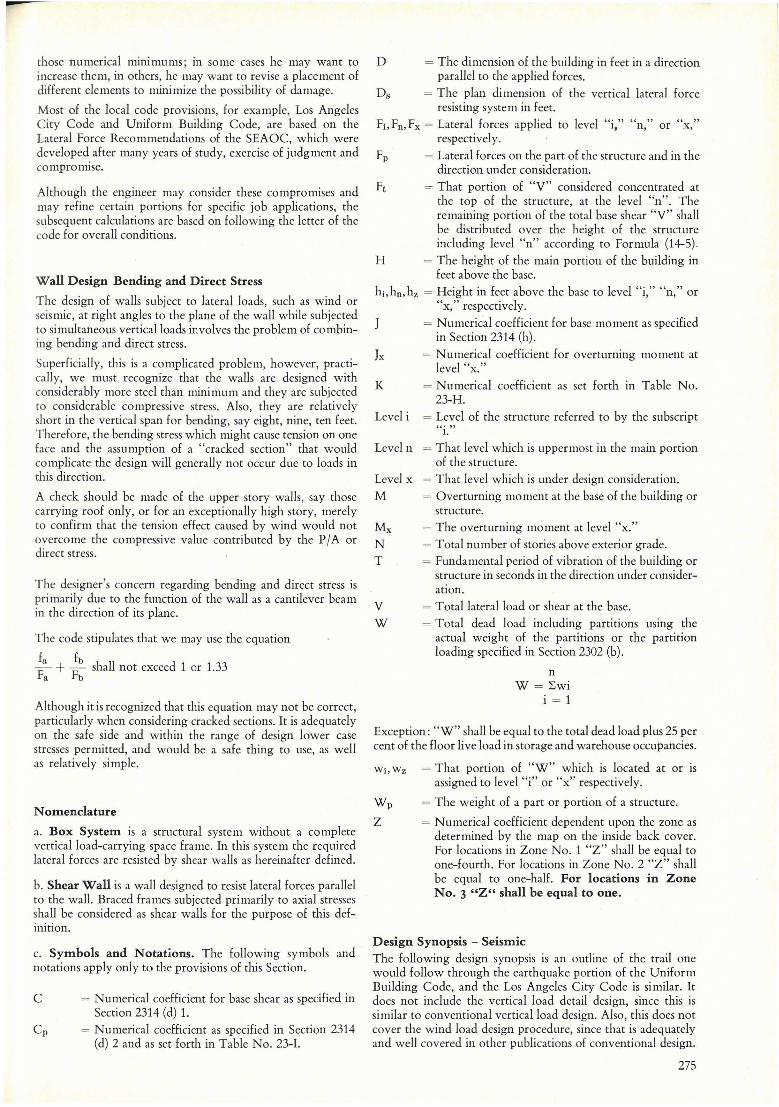
N omenclature
a. Box System is a structural system without a complete verticalload-carrying space frame. In this system the required lateral forces are resisted by shear walls as hereinafter defined.
b. Shear Wall is a wall designed to resist lateral forces parallel to the wall. Braced frames subjected primarily to axial stresses shall be considered as shear walls for the purpose of this definition.
c. Symbols and Notations. The following symbols and notations apply only to the provisions of this Section.
c = Numerical coeHicient for base shear as specified in Section 2314 (d) L
Cp = Numerical coefficient as specified in Section 2314 (d) 2 and as set forth in Table No. 23-1.
D = The dimension of the bllilding in feet in a direction paralle1 to the applied forces.
Ds = The plan dimension of the vertical lateral force resisting system in feet.
Fi, Fn, Fx = Lateral forces applied to levei "i," "n," or "x," respecti vel y.
Fp = Lateral forces 011 the part of the structure and in the direction llnder consideration.
= That portion of "Y" considered concentrated at the top of the structure, at the levei "n". The remaining portion of the total base shear "y" shall be distributed over the height of the structurc inclllding levei "n" according to Formula (14-5).
H = The height of the main POrtiOll of lhe building in feet above the base.
hi, hn, hz = Height in feet above the base to levei "i," "n," or "x," respectively.
= Numerical coeHicient for base moment as specified in Section 2314 (h).
Ix = Numerical coeHicient for overturning moment at levei "x."
K = Numerical coefficient as set forth in Table No. 23-H.
Levei i = Levei of the strllcture rcferred to by the subscript "~o "
lo
Levei n = That levei which is uppermost in the main portion of the structure.
Levei x = That levei which is under design consideration.
M = Overturning moment at the base of the building or structure.
Mx = The overturning moment at levei "x."
N = Total number of stories above exterior grade.
T = Fundamental reriod of vibration of the building or structure in seconds in the direction under consideration.
Y = Totallateralload or shear at the base.
W = Total dead load including partitions using the actual weight of the partitions or the partition loading specified in Section 2302 (b).
n W = ~wi
i = 1
Exception: "w" shall be equal to the total dead load plus 25 per cent of the floar live load in storage and warehouse occupancies.
Wi, Wz = That portion of "w" which is located at or IS assigned to levei "i" or "x" respectively.
W p = The weight of a part or portion of a structure.
Z = Numerical coefficient dependent upon the zone as determined by the map on the inside back cover. For locations in Zone No. 1 "z" shall be equal to one-fourth. For locations in Zone No. 2 "z" shall be equal to one-half. For locations in Zone No. 3 "Z" shall be equal to one.
Design Synopsis - Seismic The following design synopsis is an outline of the trail one would follow through the earthquake portion of the Uniform Bllilding Code, and the Los Angeles City Code is similar. It does not inclllde the vertical load detail design, since this is similar to conventional verticalload designo AIso, this does not cover the wind load design procedure, since that is adequately and well covered in other publications of conventional designo
275
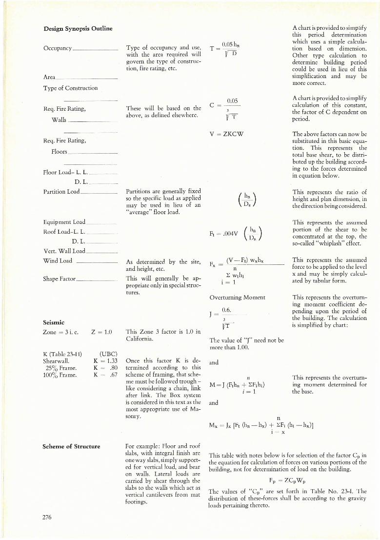
Design Synopsis Outline
Occupancy ______ _
Area
Type of Construction
Req. Fire Rating,
walls ______ _
Req. Fire Rating,
Floors
FIoor Load- L. L. __ _
D.1. ___ _
Partition Load _ ____ _
Equipment Load ____ _
Roof Load-1. L.
D.1. ___ _
Vert. Wall Load ___ _
WindLoad
Shape Factor _ _ _ __ _
Seismic
Zone = 3 i. e.
K (Tablc 23-H) Shearwall. 25% Frame.
100% Frame.
Z = 1.0
(UBC) K = 1.33 K = .80 K = .67
Scheme of Structure
276
Type of occupancy and use, with the area required will govern the type of construction, fire rating, etc.
These will be based on the above, as defined elsewhere.
Partitions are generally fixed so the specific load as applied may be used in lieu of an "average" fIoor load.
As determined by the site, and height, etc.
This will generally be appropriate only in special structtlres.
This Zone 3 factor is 1.0 in California.
Once this factor K is determined according to this scheme of framing, that scheme must be followed trough -like considering a chain, link after link. The Box system is considered in this text as the most appropriate use of Masonry.
For example: Floor and roof slabs, with integral finish are one way slabs, simply supported for verticaIload, and bear on walIs. Lateral loads are carried by shear through the slabs to the walls which act as vertical cantilevers from mat footings .
0.05 C = - -
v = ZKCW
(~) Ds
( hn ) Ft = .004V Ds
(V -Ft) wxhx -----
n ~ Wihi
i = 1
Overturning Moment
J = _0._6. __ 3
Vr The value of ''1'' need not be more than 1.00.
and
It
M = J (Fthn + ~Fihi) i = 1
and
n
A chart is provided to simplify this period determination which uses a simple calculation based on dimensiono Other type calculation to determine building period could be used in lieu of this simplification and may be more correct.
A chart is provided to simplify calculation of tbis constant, the facto r of C clependent on period.
The above factors can now be substituted in this basic equation. This represents the total base shear, to be distributed up the building according to the forces determined in equation below.
This represents the ratio of height and plan dimension, in the direction being considered.
This represents the assumed portion of the shear to be concentrated at the top, the so-called "whiplash" effect.
This represents the assumed force to be applied to the level x and may be simply calculated by tabular formo
This represents the overturning moment coefficient depending upon the period of the building. The calculation is simplified by chart:
This represents the overturning moment determined for the base.
Mx = ]x [Ft (hn - hx) -J:- ~Fi (hi - hx)] 1 = x
This table with notes below is for selection of the factor Cp in the equation for calculation of forces on various portions of the building, not for determination of load on the building.
Fp = ZCpWp
The values of "Cp" are set forth in Table No. 23-1. The distribution of these-forces shall be according to the gravity loads pertaining thereto.
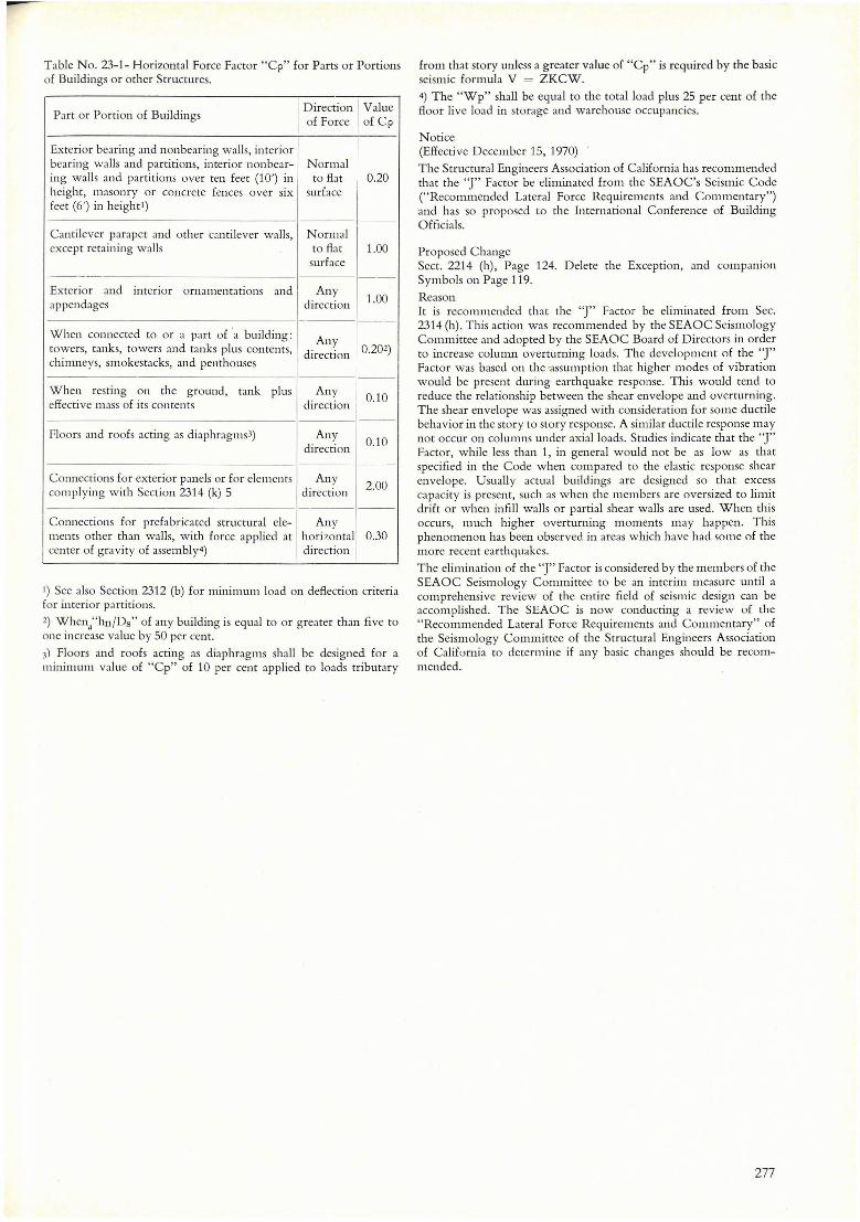
T able No. 23-1- Horizontal Force Factor "Cp" for Parts or Portions of Buildings or other Structures.
Part or Portion of Buildings I Direction I Value of Force of Cp
Exterior bearing and nonbearing walls, interior bearing walls and partitions, interior nonbear- Normal ing walls and partitions over ten feet (10') in to flat 0.20 height, masonry or concrete fences over six surface
1-feet (6') in height l )
Cantilever parapet and other cantilcver walls, Normal except retaining walls to flat 1.00
surface ___ o
--
Exterior and interior ornamentations and Any 1.00 appendages direction
When connected to or a part of 'a bllilding: Any towers, tanks, towers and tanks plus contents, direction 0.202)
chimneys, smokestacks, and penthouses
When resting on the ground, tank plus Any 0.10
effective mass of its contents direction
Floors and roofs acting as diaphragms 3) Any 0.10
direction
Connections for exterior panels ar for e1CllIcntS Any 2.00 complying with Section 2314 (k) 5 direction ---
Connections for prefabricated structural ele- Any ments other than walls, with force applied at horizontal 0.30 center of gravity of assembly4) direction
I) See also Section 2312 (b) for minimum load on deflection cri teria for interior partitions.
2) When;'hn/Ds" of any building is eqllal to or greater than five to one increase value by 50 per cento
3) Floors and roofs acting as diaphragms shall be designed for a minimum value of "Cp" of 10 per cent applied to loads tributary
from that story unless a greater value of "Cp" is required by the basic seismic formula V = ZKCW.
4) The "Wp" shall be equal to the totalload plus 25 per cent of the floor li ve loaci in storage and wareholise occupancies.
Notice (Effective December 15, 1970)
The Strllctural Engineers Association of California has recommended that the "J" Factor be eliminated from the SEAOC's Seismic Code ("Recommended Lateral Force Requirements and Coml11entary") and has so proposed to the International Conference of Building Officials.
Proposed Change Sect. 2214 (h), Page 124. Delete the Exception, and companion Symbols on Page 119.
Reason It is recol11mended that the "J" Factor be elil11inated from Seco 2314 (h). This action was recommended by the SEAOC Seismology Committee and adopted by the SEAOC Board of Directors in order to increase column overtllrning loads. The development of the "J" Factor was based on the 'assum ption that higher modes of vibration wOllld be present during earthquake response. This would tend to redllce the relationship between the shear envelope and overturning. The shear envelope was assigned with consideration for some ductile behavior in the story to story response. A similar ductile response l11ay not occur on colul11ns under axialloads. Studies indicate that the "J" Factor, while less than 1, in general would not be as low as that specified in the Co de when compared to the elastic response shear envelope. Usually actual buildings are designed so that excess capacity is present, such as when the members are oversized to limit drift or when infill walls or partial shear walls are used. When this occurs, much higher overturning moments may happen. This phenomenon has been observed in areas which have had some of the more recent earthquakes.
The elimination of the "J" Factor is considered by the l11embers of the SEAOC Seismology Committee to be 3n interim measure until a comprehensive review of the entire field of seismic design can be accomplished. The SEAOC is now conducting a review of the "Recommended Lateral Force Requirements and Commentary" of the Seismology Committee of the Structural Engineers Association of Califurnia to determine if any basic changes should be recommended.
277