GB INSTALLATION INSTRUCTIONS BUS MODULE...
34
MONTAGE – EINSTELLUNG BUSMODUL CIB MONTAGE – REGLAGE MONTAGE - INSTELLING MODULE DE BUS CIB BUSMODULE CIB MONTAGGIO–TARATURA MODULO BUS CIB INSTALLATION INSTRUCTIONS BUS MODULE CIB D GB F I BE NL BE
-
Upload
duongxuyen -
Category
Documents
-
view
212 -
download
0
Transcript of GB INSTALLATION INSTRUCTIONS BUS MODULE...
MONTAGE – EINSTELLUNG BUSMODUL CIB
MONTAGE – REGLAGE
MONTAGE - INSTELLING
MODULE DE BUS CIB
BUSMODULE CIB
MONTAGGIO–TARATURA MODULO BUS CIB
INSTALLATION INSTRUCTIONS BUS MODULE CIB
D
GB
F
I
BE
NL
BE
2
Die Arbeiten müssen von einer elektrotechnischen Fachkraftdurchgeführt werden.
Wichtige Hinweise für die Montage, Bedienung, Einstellung undWartung werden mit diesem Symbol gekennzeichnet.
Die Einstelltafeln dieser Anleitung und die Einstelltafeln der Brennwert-Heizkessel WGB 2, WGB-K sind zu beachten!
Allgemeine Sicherheitshinweise
Elektroinstallation:
Wichtige Hinweise:
Erstinbetriebnahme:
Deutsch D
3
Verwendung
Lieferumfang
Elektrische Installation
Technische DatenBusmodul CIB
Busleitungen
Busverbindung herstellen
Wichtig! Kein Ring!
EMV-gerechte Installation- Problematik
- Kabelführung
- Kabelart
Begrenzung durch Leitungs-Widerstand R:Begrenzung durchLeitungskapazität C:
Das Busmodul CIB ist vorgesehen für den Einsatz im Brennwert-Heizkesselder Serie WGB 2, WGB-K. Es ist erforderlich für die Busanbindung der Kesselzu den EUROCONTROL-Reglern:- Zonenregler ZR EC 1/2, ZR EC MSR und EC MFR sowie- EUROCONTROL BCA 2 (für weitere Kessel ist je 1 Busmodul notwendig)
– Busmodul CIB (Typ OCI 420)– Steckverbinder X41– Flachbandleitung CIB → BMU– Kabelverschraubung mit Gegenmutter
Netzspannung: 1/N/PE, AC 230 V 50 HzDie Arbeiten müssen von einer elektrotechnisch unterwiesenen Persondurchgeführt werden. Örtliche und VDE-Bestimmungen beachten.
Spannung ~ 15 V DC, 50 mA
Busleitungen führen keine Netzspannung, sondern Schutzkleinspannung. Siesollen nicht parallel mit Netzleitungen geführt werden (Störsignale).
Bei der Busverbindung zwischen der Steuer- und Regelzentrale BMU desWGB 2 und angeschlossenen EUROCONTROL-Reglern ist wie folgtvorzugehen:Die EUROCONTROL-Regler können unter Beachtung der Leitungslängenund der max. Netzausdehnung an beliebiger Stelle an den Bus angeschlosssenwerden. Die Busleitung ist polrichtig an die jeweiligen Klemmen DB und MBanzuschließen (siehe Schaltpläne der entsprechen EUROCONTROL).Eine Anordnung der Busverbindung als Ring ist nicht zulässig (Abb. 2)!
Jede Netzleitung führt Störungen mit sich. Kurzzeitige Spannungsspitzenwerden hauptsächlich durch Schaltvorgänge von induktiven Lasten wie z.B.Motoren, Schützen, Pumpen oder Magnetventilen verursacht. Diese Spannungsspitzen koppeln in benachbarte Busleitungen und können zuunerwarteten Störungen von Anlagen oder Anlagenteilen führen.Die Busleitungen sollen gegenüber Leitungen mit Netzspannungen in einemempfohlenen Abstand von 15 bis 20 cm verlegt werden. Andernfalls sindabgeschirmte Leitungen zu verwenden!Für die Busverbindung ist ein zweiadriges, verdrilltes Kabel mit einemLeitungsquerschnitt von 1,5 mm≈ zu verwenden.Bei großen Abständen zwischen den EUROCONTROL-Reglern sind folgendeBedingungen einzuhalten:Max. Leitungslänge: - 250 m pro EUROCONTROL (EC)
- max. 1000 m zwischen den entferntesten ECMax. Leitungslänge: - 250 m pro EUROCONTROL
- max. 1400 m (Summe aller Stränge bei 100pF/m)Max. Leitungs-Kapazität: - 25 nZ pro EUROCONTROL
- max. 140 nF (Summe aller Stränge)
Deutsch D

4
Kessel WGB 2 CIB
Zonenregler EC 1/2
Kessel 2
Kessel 3
Kessel 4
alte
rnat
iv
Kessel 1
Zonenregler EC 1/2
BusmodulCIB
Zonenregler EC MSR
Zonenregler EC 1/2
Zonenregler EC 1/2
Zonenregler EC 1/2
Zonenregler EC MSR
BusmodulCIB
BusmodulCIB
BusmodulCIB
EC BCA 2
Zonenregler EC MSR
Abb. 1a Prinzipschaltbild des Busmodul CIB
Abb. 1b Prinzipschaltbild des Busmodul CIBKesselfolgeschaltung EUROCONTROL BCA 2 mit Mischer
EC BCA ZR EC 1/2
ZR EC 1/2
EC MSR
EC MSR
EC BCA ZR EC 1/2
ZR EC 1/2EC MSR
EC BCA ZR EC 1/2
ZR EC 1/2
EC MSRZR EC 1/2
ZR EC 1/2EC MSR
EC MSR
ZR EC 1/2
Abb. 2 Möglichkeiten der Busverbindung zu EUROCONTROL-Reglern
Tab. 1 Funktionen der Steuer- und Regelzentrale BMU
Brennwert-Heizkessel WGB 2 bzw. WGB-K: Sonderzubehör● Integrierte Steuer-und Regelzentrale BMU
- witterungsgeführte gleitende Regelung der Kesseltemp.- modulierende Betriebsweise- Pumpenheizkreis (Heizkreis 1)
- Pumpen- bzw. Mischerheizkreis über Busmodul CIB aufschaltbar Zonenregler ZR EC 1/2, ZR EC MSR bzw. EC MFR- Kesselfolgeschaltung EUROCONTROL BCA 2
Deutsch D
5
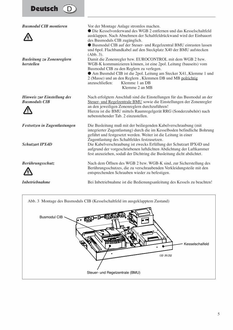
Vor der Montage Anlage stromlos machen.● Die Kesselvorderwand des WGB 2 entfernen und das Kesselschaltfeldausklappen. Nach Abnehmen der Schaltfeldrückwand wird der Einbauortdes Busmoduls CIB zugänglich.● Busmodul CIB auf der Steuer- und Regelzentral BMU einrasten lassenund 6pol. Flachbandkabel auf den Steckplatz X40 der BMU aufstecken(Abb. 3).Damit die Zonenregler bzw. EUROCONTROL mit dem WGB 2 bzw.WGB-K kommunizieren können, ist eine 2pol. Leitung (bauseits) vomBusmodul CIB zu den Reglern zu verlegen.● Am Busmdul CIB ist die 2pol. Leitung am Stecker X41, Klemme 1 und2 (Masse) und an den Reglern , Klemmen DB und MB polrichtiganzuschließen: Klemme 1 an DB
Klemme 2 an MB
Nach erfolgtem Anschluß sind die Einstellungen für das Busmodul an derSteuer- und Regelzentrale BMU sowie die Einstellungen der Zonenregleran den jeweiligen Zonenreglern durchzuführen!Hierzu ist die BMU mittels Raumregelgerät RRG (Sonderzubehör) nachnebenstehender Tab. 2 einzustellen.
Die Busleitung muß mit der beiliegenden Kabelverschraubung (mitintegrierter Zugentlastung) durch die im Kesselboden befindliche Bohrunggeführt und festgesetzt werden. Weiter ist die Leitung in einerZugentlastung des Schaltfeldes festzusetzen.Die Kabelverschraubung ist zwecks Erfüllung der Schutzart IPX4D undaufgrund der vorgeschriebenen luftdichten Abdichtung der Luftkammerfest anzuziehen, sodaß der Dichtring die Busleitung dicht abdichtet.
Nach dem Öffnen des WGB 2 bzw. WGB-K sind, zur Sicherstellung desBerührungsschutzes, die zu verschraubenden Verkleidungsteile mit denentsprechenden Schrauben wieder zu befestigen.
Bei Inbetriebnahme ist die Bedienungsanleitung des Kessels zu beachten!
Busmodul CIB montieren
Busleitung zu Zonenreglernherstellen
Hinweis zur Einstellung desBusmoduls CIB
Festsetzen in Zugentlastungen
Schutzart IPX4D
Berührungsschutz
Inbetriebnahme
Kesselschalfeld
Steuer- und Regelzentrale (BMU)
Busmodul CIB
Abb. 3 Montage des Busmoduls CIB (Kesselschaltfeld im ausgeklapptem Zustand)
Deutsch D
6
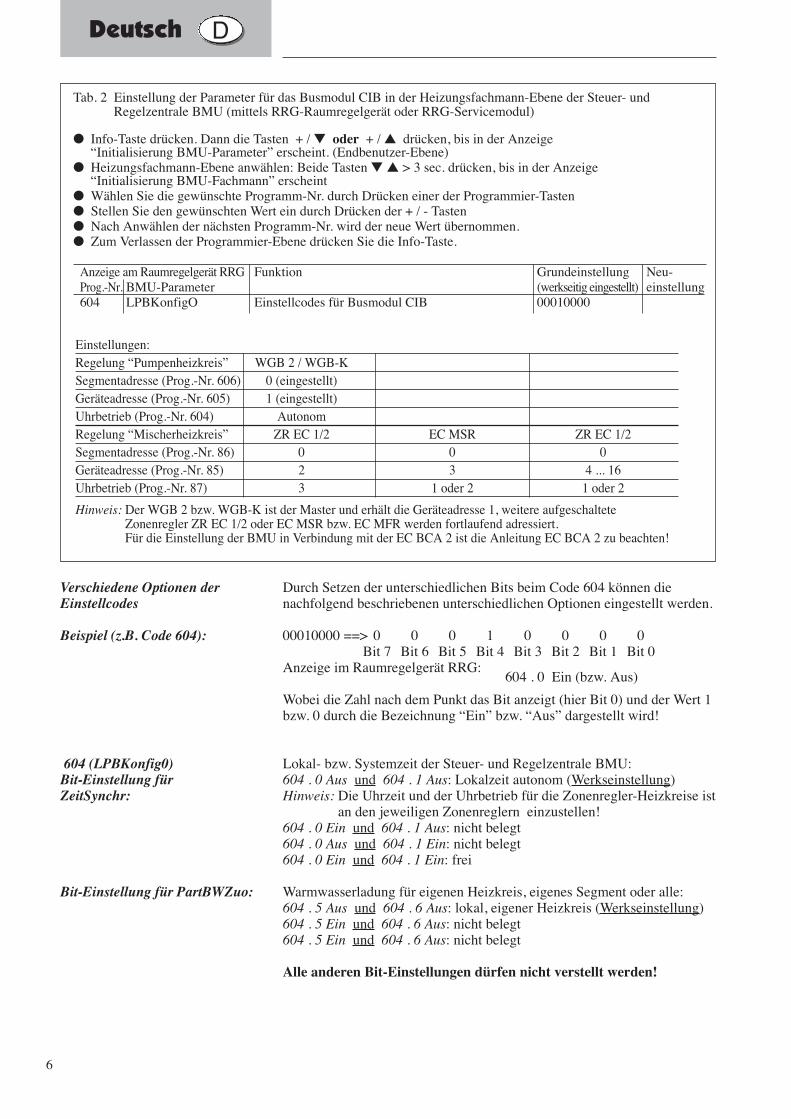
Durch Setzen der unterschiedlichen Bits beim Code 604 können dienachfolgend beschriebenen unterschiedlichen Optionen eingestellt werden.
00010000 ==> 0 0 0 1 0 0 0 0Bit 7 Bit 6 Bit 5 Bit 4 Bit 3 Bit 2 Bit 1 Bit 0
Anzeige im Raumregelgerät RRG:604 . 0 Ein (bzw. Aus)
Wobei die Zahl nach dem Punkt das Bit anzeigt (hier Bit 0) und der Wert 1bzw. 0 durch die Bezeichnung “Ein” bzw. “Aus” dargestellt wird!
Lokal- bzw. Systemzeit der Steuer- und Regelzentrale BMU:604 . 0 Aus und 604 . 1 Aus: Lokalzeit autonom (Werkseinstellung)Hinweis: Die Uhrzeit und der Uhrbetrieb für die Zonenregler-Heizkreise ist
an den jeweiligen Zonenreglern einzustellen!604 . 0 Ein und 604 . 1 Aus: nicht belegt604 . 0 Aus und 604 . 1 Ein: nicht belegt604 . 0 Ein und 604 . 1 Ein: frei
Warmwasserladung für eigenen Heizkreis, eigenes Segment oder alle:604 . 5 Aus und 604 . 6 Aus: lokal, eigener Heizkreis (Werkseinstellung)604 . 5 Ein und 604 . 6 Aus: nicht belegt604 . 5 Ein und 604 . 6 Aus: nicht belegt
Alle anderen Bit-Einstellungen dürfen nicht verstellt werden!
Verschiedene Optionen derEinstellcodes
Beispiel (z.B. Code 604):
604 (LPBKonfig0)Bit-Einstellung für ZeitSynchr:
Bit-Einstellung für PartBWZuo:
Tab. 2 Einstellung der Parameter für das Busmodul CIB in der Heizungsfachmann-Ebene der Steuer- undRegelzentrale BMU (mittels RRG-Raumregelgerät oder RRG-Servicemodul)
● Info-Taste drücken. Dann die Tasten + / ▼ oder + / ▲ drücken, bis in der Anzeige “Initialisierung BMU-Parameter” erscheint. (Endbenutzer-Ebene)
● Heizungsfachmann-Ebene anwählen: Beide Tasten ▼ ▲ > 3 sec. drücken, bis in der Anzeige “Initialisierung BMU-Fachmann” erscheint
● Wählen Sie die gewünschte Programm-Nr. durch Drücken einer der Programmier-Tasten● Stellen Sie den gewünschten Wert ein durch Drücken der + / - Tasten● Nach Anwählen der nächsten Programm-Nr. wird der neue Wert übernommen.● Zum Verlassen der Programmier-Ebene drücken Sie die Info-Taste.
Anzeige am Raumregelgerät RRG Funktion Grundeinstellung Neu-Prog.-Nr. BMU-Parameter (werkseitig eingestellt) einstellung604 LPBKonfigO Einstellcodes für Busmodul CIB 00010000
Einstellungen:Regelung “Pumpenheizkreis” WGB 2 / WGB-KSegmentadresse (Prog.-Nr. 606) 0 (eingestellt)Geräteadresse (Prog.-Nr. 605) 1 (eingestellt)Uhrbetrieb (Prog.-Nr. 604) AutonomRegelung “Mischerheizkreis” ZR EC 1/2 EC MSR ZR EC 1/2 Segmentadresse (Prog.-Nr. 86) 0 0 0Geräteadresse (Prog.-Nr. 85) 2 3 4 ... 16Uhrbetrieb (Prog.-Nr. 87) 3 1 oder 2 1 oder 2
Hinweis: Der WGB 2 bzw. WGB-K ist der Master und erhält die Geräteadresse 1, weitere aufgeschalteteZonenregler ZR EC 1/2 oder EC MSR bzw. EC MFR werden fortlaufend adressiert.Für die Einstellung der BMU in Verbindung mit der EC BCA 2 ist die Anleitung EC BCA 2 zu beachten!
Deutsch D
7
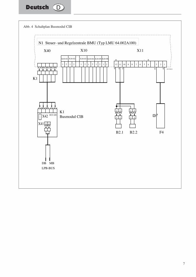
K1Busmodul CIB
K1
1 2
X40 X10 X11
X10-04 X10-05 X10-06
1 2 1 2 1 2 1 21 2 1 2
X10-01 X10-02 X10-03
F4
123456789101112
1 2
B2.1
1 2
1 2
B2.2
1 2
rt rs vi or or
- ++
N1 Steuer- und Regelzentrale BMU (Typ LMU 64.002A100)
X41
X42 OCI 420
LPB-BUS
DB MB
59-272029.4
Abb. 4 Schaltplan Busmodul CIB
Deutsch D
8
The Work must be carried out by a qualified electricians.
Important instructions and information for installation, operationand maintenance are marked with this symbol.
The adjustment detains and settings in these instructions and theadjustment detains and setting in the boiler manuel must be taken intoaccount!
General safety instructions
Electrical installation:
Important instructions:
Putting into service for thefirst time:
English GB
9
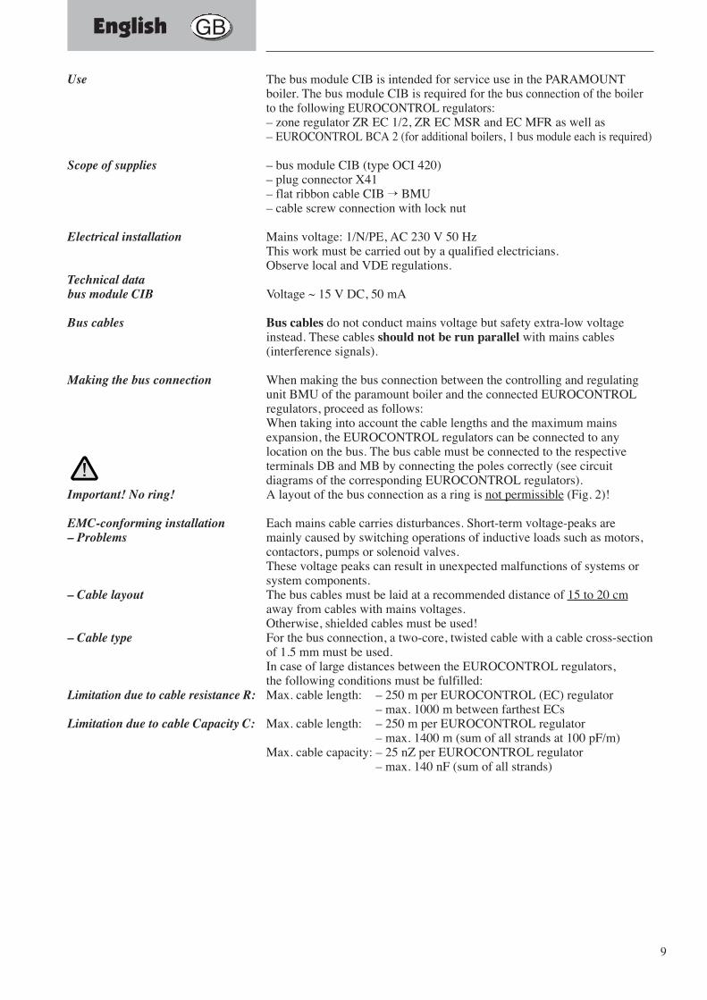
Use
Scope of supplies
Electrical installation
Technical databus module CIB
Bus cables
Making the bus connection
Important! No ring!
EMC-conforming installation– Problems
– Cable layout
– Cable type
Limitation due to cable resistance R:
Limitation due to cable Capacity C:
The bus module CIB is intended for service use in the PARAMOUNTboiler. The bus module CIB is required for the bus connection of the boilerto the following EUROCONTROL regulators:– zone regulator ZR EC 1/2, ZR EC MSR and EC MFR as well as– EUROCONTROL BCA 2 (for additional boilers, 1 bus module each is required)
– bus module CIB (type OCI 420)– plug connector X41– flat ribbon cable CIB → BMU– cable screw connection with lock nut
Mains voltage: 1/N/PE, AC 230 V 50 HzThis work must be carried out by a qualified electricians.Observe local and VDE regulations.
Voltage ~ 15 V DC, 50 mA
Bus cables do not conduct mains voltage but safety extra-low voltageinstead. These cables should not be run parallel with mains cables(interference signals).
When making the bus connection between the controlling and regulatingunit BMU of the paramount boiler and the connected EUROCONTROLregulators, proceed as follows:When taking into account the cable lengths and the maximum mainsexpansion, the EUROCONTROL regulators can be connected to anylocation on the bus. The bus cable must be connected to the respectiveterminals DB and MB by connecting the poles correctly (see circuitdiagrams of the corresponding EUROCONTROL regulators).A layout of the bus connection as a ring is not permissible (Fig. 2)!
Each mains cable carries disturbances. Short-term voltage-peaks aremainly caused by switching operations of inductive loads such as motors,contactors, pumps or solenoid valves.These voltage peaks can result in unexpected malfunctions of systems orsystem components.The bus cables must be laid at a recommended distance of 15 to 20 cmaway from cables with mains voltages.Otherwise, shielded cables must be used!For the bus connection, a two-core, twisted cable with a cable cross-sectionof 1.5 mm must be used.In case of large distances between the EUROCONTROL regulators,the following conditions must be fulfilled:Max. cable length: – 250 m per EUROCONTROL (EC) regulator
– max. 1000 m between farthest ECsMax. cable length: – 250 m per EUROCONTROL regulator
– max. 1400 m (sum of all strands at 100 pF/m)Max. cable capacity: – 25 nZ per EUROCONTROL regulator
– max. 140 nF (sum of all strands)
English GB
10
Kessel WGB 2 CIB
Zonenregler EC 1/2
Kessel 2
Kessel 3
Kessel 4
alte
rnat
iv
Kessel 1
Zonenregler EC 1/2
BusmodulCIB
Zonenregler EC MSR
Zonenregler EC 1/2
Zonenregler EC 1/2
Zonenregler EC 1/2
Zonenregler EC MSR
BusmodulCIB
BusmodulCIB
BusmodulCIB
EC BCA 2
Zonenregler EC MSR
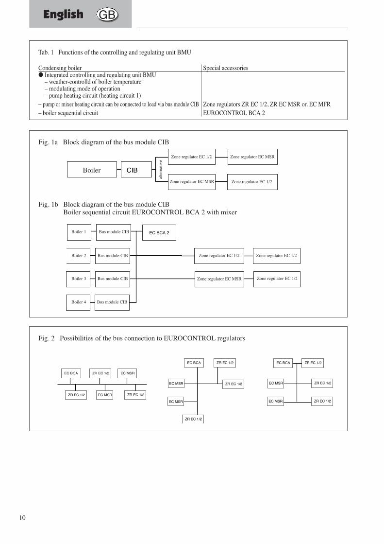
Fig. 1a Block diagram of the bus module CIB
Fig. 1b Block diagram of the bus module CIBBoiler sequential circuit EUROCONTROL BCA 2 with mixer
EC BCA ZR EC 1/2
ZR EC 1/2
EC MSR
EC MSR
EC BCA ZR EC 1/2
ZR EC 1/2EC MSR
EC BCA ZR EC 1/2
ZR EC 1/2
EC MSRZR EC 1/2
ZR EC 1/2EC MSR
EC MSR
ZR EC 1/2
Fig. 2 Possibilities of the bus connection to EUROCONTROL regulators
Tab. 1 Functions of the controlling and regulating unit BMU
Condensing boiler Special accessories● Integrated controlling and regulating unit BMU
– weather-controlld of boiler temperature– modulating mode of operation– pump heating circuit (heating circuit 1)
– pump or mixer heating circuit can be connected to load via bus module CIB Zone regulators ZR EC 1/2, ZR EC MSR or. EC MFR– boiler sequential circuit EUROCONTROL BCA 2
Boiler
Zone regulator EC 1/2
Zone regulator EC 1/2 Zone regulator EC 1/2
Zone regulator EC 1/2
Boiler 1 Bus module CIB
Bus module CIB
Bus module CIB
Bus module CIB
Boiler 2
Boiler 3
Boiler 4
Zone regulator EC 1/2
Zone regulator EC MSR
Zone regulator EC MSR
Zone regulator EC MSR
alte
rnat
ive
English GB
11
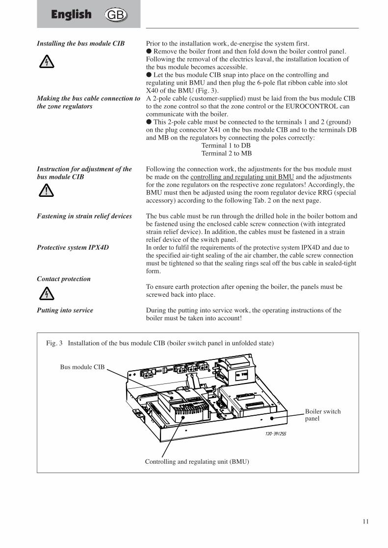
Prior to the installation work, de-energise the system first.● Remove the boiler front and then fold down the boiler control panel.Following the removal of the electrics leaval, the installation location ofthe bus module becomes accessible.● Let the bus module CIB snap into place on the controlling andregulating unit BMU and then plug the 6-pole flat ribbon cable into slotX40 of the BMU (Fig. 3).A 2-pole cable (customer-supplied) must be laid from the bus module CIBto the zone control so that the zone control or the EUROCONTROL cancommunicate with the boiler.● This 2-pole cable must be connected to the terminals 1 and 2 (ground)on the plug connector X41 on the bus module CIB and to the terminals DBand MB on the regulators by connecting the poles correctly:
Terminal 1 to DBTerminal 2 to MB
Following the connection work, the adjustments for the bus module mustbe made on the controlling and regulating unit BMU and the adjustmentsfor the zone regulators on the respective zone regulators! Accordingly, theBMU must then be adjusted using the room regulator device RRG (specialaccessory) according to the following Tab. 2 on the next page.
The bus cable must be run through the drilled hole in the boiler bottom andbe fastened using the enclosed cable screw connection (with integratedstrain relief device). In addition, the cables must be fastened in a strainrelief device of the switch panel.In order to fulfil the requirements of the protective system IPX4D and due tothe specified air-tight sealing of the air chamber, the cable screw connectionmust be tightened so that the sealing rings seal off the bus cable in sealed-tightform.
To ensure earth protection after opening the boiler, the panels must bescrewed back into place.
During the putting into service work, the operating instructions of theboiler must be taken into account!
Installing the bus module CIB
Making the bus cable connection tothe zone regulators
Instruction for adjustment of thebus module CIB
Fastening in strain relief devices
Protective system IPX4D
Contact protection
Putting into service
Kesselschalfeld
Steuer- und Regelzentrale (BMU)
Busmodul CIB
Fig. 3 Installation of the bus module CIB (boiler switch panel in unfolded state)
Bus module CIB
Controlling and regulating unit (BMU)
Boiler switchpanel
English GB
12
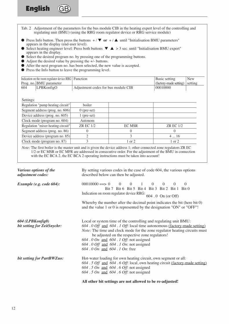
By setting various codes in the case of code 604, the various optionsdescribed below can then be adjusted.
00010000 ==> 0 0 0 1 0 0 0 0Bit 7 Bit 6 Bit 5 Bit 4 Bit 3 Bit 2 Bit 1 Bit 0
Indication on room regulator device RRG:604 . 0 On (or Off)
Whereby the number after the decimal point indicates the bit (here bit 0)and the value 1 or 0 is represented by the designation "ON" or "OFF"!
Local or system time of the controlling and regulating unit BMU:604 . 0 Off and 604 . 1 Off: local time autonomous (factory-made setting)Note: The time and clock mode for the zone regulator heating circuits must
be adjusted on the respective zone regulators!604 . 0 On and 604 . 1 Off: not assigned604 . 0 Off and 604 . 1 On: not assigned604 . 0 On and 604 . 1 On: free
Hot-water loading for own heating circuit, own segment or all:604 . 5 Off and 604 . 6 Off: local, own heating circuit (factory-made setting)604 . 5 On and 604 . 6 Off: not assigned604 . 5 On and 604 . 6 Off: not assigned
All other bit settings are not allowed to be re-adjusted!
Various options of theadjustment codes:
Example (e.g. code 604):
604 (LPBKonfig0)bit setting for ZeitSnychr:
bit setting for PartBWZuo:
Tab. 2 Adjustment of the parameters for the bus module CIB in the heating expert level of the controlling andregulating unit (BMU) (using the RRG room regulator device or RRG service module)
● Press Info button. Then press the buttons + / ▼ or + / ▲ until "Initialisation BMU parameters"appears in the display (end-user level).
● Select heating engineer level: Press both buttons ▼ ▲ > 3 sec. until "Initialisation BMU expert"appears in the display.
● Select the desired program no. by pressing one of the programming buttons.● Adjust the desired value by pressing the +/- buttons.● After the next program no. has been selected, the new value is accepted.● Press the Info button to leave the programming level.
Indication on the room regulator device RRG Function Basic setting NewProg. no. BMU parameter (factory-made setting) setting604 LPBKonfigO Adjustment codes for bus module CIB 00010000
Settings:Regulation "pump heating circuit" boilerSegment address (prog. no. 606) 0 (pre-set)Device address (prog. no. 605) 1 (pre-set)Clock mode (program no. 604) AutonomRegulation "mixer heating circuit" ZR EC 1/2 EC MSR ZR EC 1/2 Segment address (prog. no. 86) 0 0 0Device address (program no. 85) 2 3 4 ... 16Clock mode (program no. 87) 3 1 or 2 1 or 2
Note: The first boiler is the master unit and is given the device address 1; other connected zone regulators ZR EC1/2 or EC MSR or EC MFR are addressed in consecutive order. For the adjustment of the BMU in connectionwith the EC BCA 2, the EC BCA 2 operating instructions must be taken into account!
English GB

13
K1Busmodul CIB
K1
1 2
X40 X10 X11
X10-04 X10-05 X10-06
1 2 1 2 1 2 1 21 2 1 2
X10-01 X10-02 X10-03
F4
123456789101112
1 2
B2.1
1 2
1 2
B2.2
1 2
rt rs vi or or
- ++
N1 Steuer- und Regelzentrale BMU (Typ LMU 64.002A100)
X41
X42 OCI 420
LPB-BUS
DB MB
59-272029.4
Fig. 4 Circuit diagram – bus module CIB
N1 controlling and regulating unit BMU (type LM U 64.002A 100)
Bus module CIB
English GB
14
France F
Les travaux doivent être confiés à un électrotechnicien agréé.
Les consignes importantes pour le montage, la commande, leréglage et l’entretien sont marquées de ce symbole.
Les panneaux de réglage des présentes instructions et les tableaux deréglage des chaudières de condensation WGB 2, WGB-K sont à observer!
Consignes générales de sécurité
Installation électrique:
Consignes importantes:
Première mise en service:
15
France F
Utilisation
Etendue de la livraison
Installation électrique
Caractéristiques techniquesModule de bus CIB
Câbles de bus
Etablissement de la liaison bus
Important! Pas d’anneau!
Installation conforme à la CEM- Problèmes
- Tracé des câbles
- Type de câble
Limitation par une résistance deligne R:Limitation par une capacité deligne C:
Le module de bus CIB est prévu pour une utilisation dans les chaudières àcondensation des séries WGB 2, WGB-K. Il est nécessaire pour la liaison busdes chaudières avec les régulateurs EUROCONTROL:- régulateur de zones ZR EC 1/2, ZR EC MSR et EC MFR ainsi que- EUROCONTROL BCA 2 (un module de bus est respectivement nécessaire
pour les autres chaudières)
– Module de bus CIB (type OCI 420)– Connecteur X41– Câble plat CIB → BMU– Raccords à vis de câble avec contre-écrou
Tension secteur: 1/N/PE, AC 230 V 50 HzLes travaux doivent être confiés à un électrotechnicien agréé. Les dispositionslocales et VDE sont à observer.
Tension ~ 15 V DC, 50 mA
Les câbles de bus ne conduisent pas de tension secteur mais une bassetension de protection. Elles ne doivent pas être posées parallèlement aux câblessecteurs (signaux perturbateurs).
Dans le cas d’une liaison bus entre la centrale de commande et de régulationBMU de la WGB 2 et les régulateurs EUROCONTROL raccordés, procédezcomme suit:Les régulateurs EUROCONTROL peuvent être raccordés en un endroitquelconque du bus sous prise en considération des longueurs des câbles et de ladilatation max. du réseau.La ligne bus doit être raccordée en respectant la polarité sur les différentesbornes DB et MB (voir schémas de câblage de l’EUROCONTROL correspondante).La disposition de la liaison bus en anneau n’est pas autorisée (fig. 2)!
Chaque câble secteur est conductrice de dérangements. Les crêtes de tensionbrèves sont principalement provoquées par des manoeuvres de commutation decharges inductives telles que p. ex. les moteurs, les contacteurs, les pompes oules électrovannes.Ces pointes de tension provoquent un couplage dans les câbles de bus voisineset peuvent provoquer des dérangements inattendus au niveau des installationset de leurs composants.Les câbles de bus doivent être posés avec un écartement recommandé de 15 à20 cm des câbles conductrices de tension secteur. Dans les autres cas, descâbles blindés doivent être utilisés!Un câble à deux conducteurs torsadés d’une section de 1,5 mm2 doit êtreutilisé pour la liaison bus.Les conditions suivantes doivent être observées lors de grandes distances entreles régulateurs EUROCONTROL:Longueur max. de: - 250 m par EUROCONTROL (EC)
- max. 1000 m entre l’EC la plus éloignéeLongueur max. de: - 250 m par EUROCONTROL
- max. 1400 m (total de tous les brins pour 100 pF/m)Capacité de ligne max.: - 25 nZ par EUROCONTROL
- max. 140 nF (total de tous les brins)
16
France F
Kessel WGB 2 CIB
Zonenregler EC 1/2
Kessel 2
Kessel 3
Kessel 4
alte
rnat
iv
Kessel 1
Zonenregler EC 1/2
BusmodulCIB
Zonenregler EC MSR
Zonenregler EC 1/2
Zonenregler EC 1/2
Zonenregler EC 1/2
Zonenregler EC MSR
BusmodulCIB
BusmodulCIB
BusmodulCIB
EC BCA 2
Zonenregler EC MSR
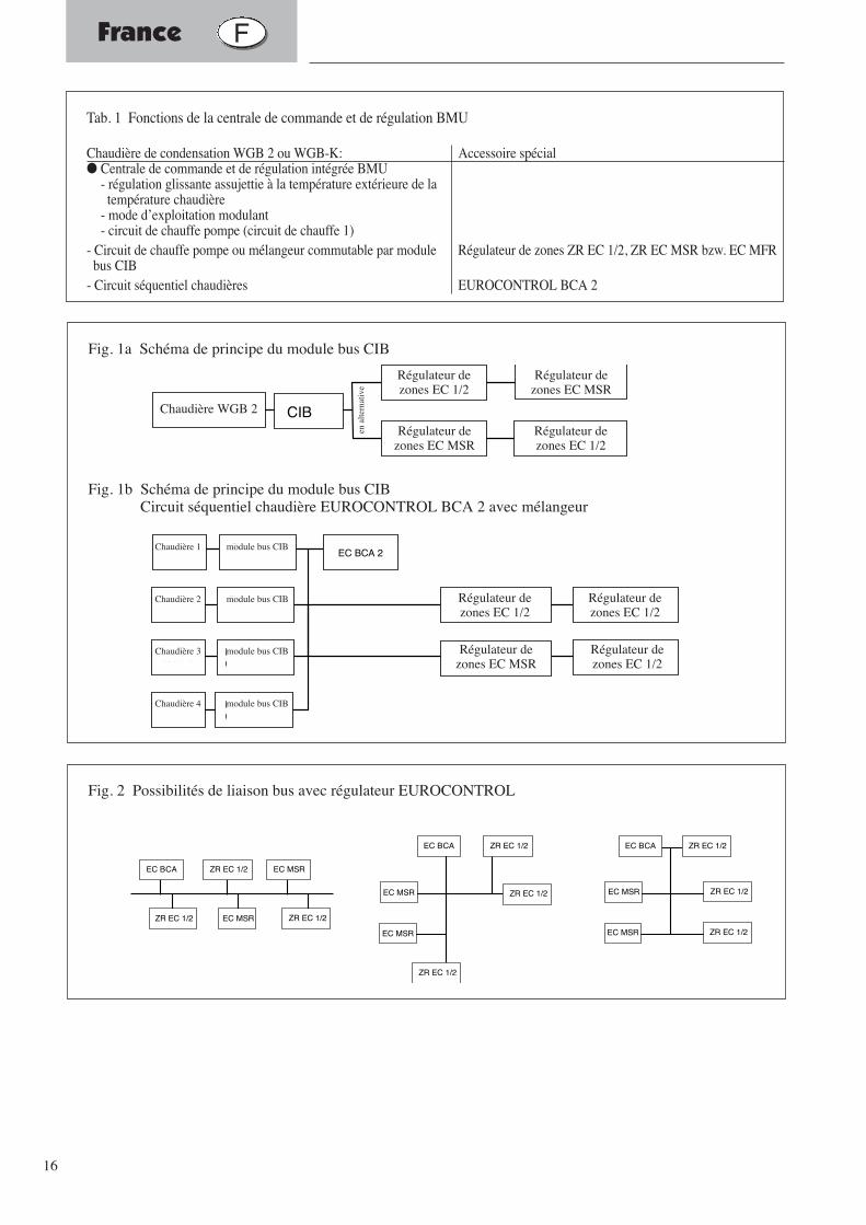
Fig. 1a Schéma de principe du module bus CIB
Fig. 1b Schéma de principe du module bus CIBCircuit séquentiel chaudière EUROCONTROL BCA 2 avec mélangeur
EC BCA ZR EC 1/2
ZR EC 1/2
EC MSR
EC MSR
EC BCA ZR EC 1/2
ZR EC 1/2EC MSR
EC BCA ZR EC 1/2
ZR EC 1/2
EC MSRZR EC 1/2
ZR EC 1/2EC MSR
EC MSR
ZR EC 1/2
Fig. 2 Possibilités de liaison bus avec régulateur EUROCONTROL
Tab. 1 Fonctions de la centrale de commande et de régulation BMU
Chaudière de condensation WGB 2 ou WGB-K: Accessoire spécial● Centrale de commande et de régulation intégrée BMU
- régulation glissante assujettie à la température extérieure de latempérature chaudière
- mode d’exploitation modulant- circuit de chauffe pompe (circuit de chauffe 1)
- Circuit de chauffe pompe ou mélangeur commutable par module Régulateur de zones ZR EC 1/2, ZR EC MSR bzw. EC MFRbus CIB
- Circuit séquentiel chaudières EUROCONTROL BCA 2
Chaudière WGB 2
Régulateur dezones EC 1/2
Régulateur dezones EC MSR
Régulateur dezones EC MSR
Régulateur dezones EC 1/2
Régulateur dezones EC 1/2
Régulateur dezones EC 1/2
Régulateur dezones EC 1/2
Régulateur dezones EC MSR
Chaudière 1
Chaudière 2
Chaudière 3
Chaudière 4
module bus CIB
module bus CIB
module bus CIB
module bus CIB
en a
ltern
ativ
e
17
France F
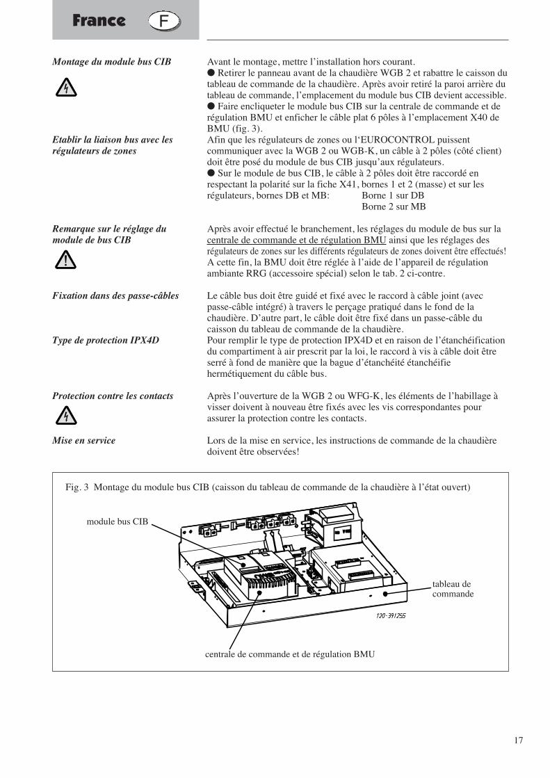
Avant le montage, mettre l’installation hors courant.● Retirer le panneau avant de la chaudière WGB 2 et rabattre le caisson dutableau de commande de la chaudière. Après avoir retiré la paroi arrière dutableau de commande, l’emplacement du module bus CIB devient accessible.● Faire encliqueter le module bus CIB sur la centrale de commande et derégulation BMU et enficher le câble plat 6 pôles à l’emplacement X40 deBMU (fig. 3).Afin que les régulateurs de zones ou l‘EUROCONTROL puissentcommuniquer avec la WGB 2 ou WGB-K, un câble à 2 pôles (côté client)doit être posé du module de bus CIB jusqu’aux régulateurs.● Sur le module de bus CIB, le câble à 2 pôles doit être raccordé enrespectant la polarité sur la fiche X41, bornes 1 et 2 (masse) et sur lesrégulateurs, bornes DB et MB: Borne 1 sur DB
Borne 2 sur MB
Après avoir effectué le branchement, les réglages du module de bus sur lacentrale de commande et de régulation BMU ainsi que les réglages desrégulateurs de zones sur les différents régulateurs de zones doivent être effectués!A cette fin, la BMU doit être réglée à l’aide de l’appareil de régulationambiante RRG (accessoire spécial) selon le tab. 2 ci-contre.
Le câble bus doit être guidé et fixé avec le raccord à câble joint (avecpasse-câble intégré) à travers le perçage pratiqué dans le fond de lachaudière. D’autre part, le câble doit être fixé dans un passe-câble ducaisson du tableau de commande de la chaudière.Pour remplir le type de protection IPX4D et en raison de l’étanchéificationdu compartiment à air prescrit par la loi, le raccord à vis à câble doit êtreserré à fond de manière que la bague d’étanchéité étanchéifiehermétiquement du câble bus.
Après l’ouverture de la WGB 2 ou WFG-K, les éléments de l’habillage àvisser doivent à nouveau être fixés avec les vis correspondantes pourassurer la protection contre les contacts.
Lors de la mise en service, les instructions de commande de la chaudièredoivent être observées!
Montage du module bus CIB
Etablir la liaison bus avec lesrégulateurs de zones
Remarque sur le réglage dumodule de bus CIB
Fixation dans des passe-câbles
Type de protection IPX4D
Protection contre les contacts
Mise en service
Kesselschalfeld
Steuer- und Regelzentrale (BMU)
Busmodul CIB
Fig. 3 Montage du module bus CIB (caisson du tableau de commande de la chaudière à l’état ouvert)
module bus CIB
centrale de commande et de régulation BMU
tableau decommande
18
France F
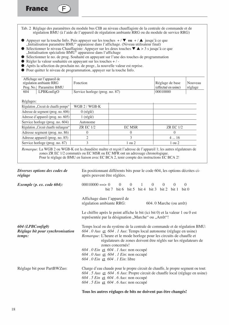
En positionnant différents bits pour le code 604, les options décrites ci-après peuvent être réglées.
00010000 ==> 0 0 0 1 0 0 0 0bit 7 bit 6 bit 5 bit 4 bit 3 bit 2 bit 1 bit 0
Affichage dans l’appareil de régulation ambiante RRG: 604. 0 Marche (ou arrêt)
Le chiffre après le point affiche le bit (ici bit 0) et la valeur 1 ou 0 estreprésentée par la désignation „Marche“ ou „Arrêt“!
Temps local ou du système de la centrale de commande et de régulation BMU:604 . 0 Aus et 604 . 1 Aus: Temps local autonome (réglage en usine)Remarque: L’heure et le mode horloge pour les circuits de chauffe et
régulateurs de zones doivent être réglés sur les régulateurs dezones concernés!
604 . 0 Ein et 604 . 1 Aus: non occupé604 . 0 Aus et 604 . 1 Ein: non occupé604 . 0 Ein et 604 . 1 Ein: libre
Charge d’eau chaude pour le propre circuit de chauffe, le propre segment ou tout:604 . 5 Aus et 604 . 6 Aus: Propre circuit de chauffe local (réglage en usine)604 . 5 Ein et 604 . 6 Aus: non occupé604 . 5 Ein et 604 . 6 Aus: non occupé
Tous les autres réglages de bits ne doivent pas être changés!
Diverses options des codes deréglage
Exemple (p. ex. code 604):
604 (LPBConfig0)Réglage bit pour synchronisationtemps:
Réglage bit pour PartBWZuo:
Tab. 2 Réglage des paramètres du module bus CIB au niveau chauffagiste de la centrale de commande et derégulation BMU (à l’aide de l’appareil de régulation ambiante RRG ou du module de service RRG)
● Appuyer sur la touche Info. Puis appuyer sur les touches + / ▼ ou + / ▲ jusqu’à ce que„Initialisation paramètre BMU“ apparaisse dans l’affichage. (Niveau utilisateur final)
● Sélectionner le niveau Chauffagiste: Appuyer sur les deux touches ▼ ▲ > 3 s jusqu’à ce que„Initialisation spécialiste BMU“ apparaisse dans l‘affichage
● Sélectionner le no. de prog. Souhaité en appuyant sur l’une des touches de programmation● Régler la valeur souhaitée en appuyant sur les touches + / -● Après la sélection du prochain no. de progr., la nouvelle valeur est reprise.● Pour quitter le niveau de programmation, appuyer sur la touche Info.
Affichage sur l’appareil derégulation ambiante RRG Fonction Réglage de base Nouveau Prog. No. Paramètre BMU (effectué en usine) réglage604 LPBKonfigO Service horloge (prog. no. 87) 00010000
Réglages:Régulation „Circuit de chauffe pompe“ WGB 2 / WGB-KAdresse de segment (prog. no. 606) 0 (réglé)Adresse d’appareil (prog. no. 605) 1 (réglé)Service horloge (prog. no. 604) AutonomeRégulation „Circuit chauffe mélangeur“ ZR EC 1/2 EC MSR ZR EC 1/2 Adresse segment (prog. no. 86) 0 0 0Adresse appareil (prog. no. 85) 2 3 4 ... 16Service horloge (prog. no. 87) 3 1 ou 2 1 ou 2
Remarque: La WGB 2 ou WGB-K est la chaudière maître et reçoit l’adresse de l’appareil 1; les autres régulateurs dezones ZR EC 1/2 commutés ou EC MSR ou EC MFR ont un adressage chronologique.Pour le réglage de BMU en liaison avec EC BCA 2, tenir compte des instructions EC BCA 2!
19
France F
K1Busmodul CIB
K1
1 2
X40 X10 X11
X10-04 X10-05 X10-06
1 2 1 2 1 2 1 21 2 1 2
X10-01 X10-02 X10-03
F4
123456789101112
1 2
B2.1
1 2
1 2
B2.2
1 2
rt rs vi or or
- ++
N1 Steuer- und Regelzentrale BMU (Typ LMU 64.002A100)
X41
X42 OCI 420
LPB-BUS
DB MB
59-272029.4
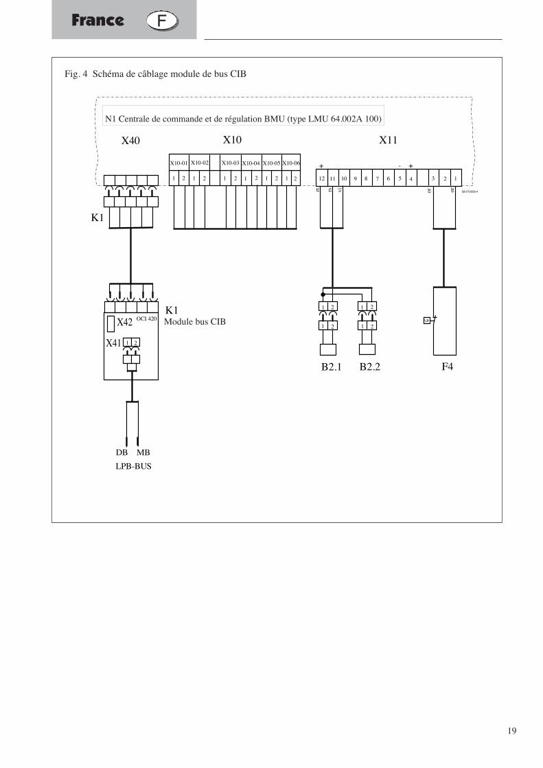
Fig. 4 Schéma de câblage module de bus CIB
N1 Centrale de commande et de régulation BMU (type LMU 64.002A 100)
Module bus CIB
20
De werkzaamheden moeten door een gediplomeerd elektricienworden uitgevoerd.
Belangrijke instructies voor de montage, bediening, instelling enhet onderhoud worden door middel van dit symbool aangeduid.
De instelpanelen van deze gebruiksaanwijzing en de instelpanelen van dehoge rendement- verwarmingsketels WGB 2, WGB-K, BBS 2 resp. SGB 2dienen in acht te worden genomen!
Algemene veiligheidsinstructies
Elektrische installatie:
Belangrijke instructies:
Eerste ingebruikname
Nederlands NL
21
Gebruik
Leveringsomvang
Elektrische installatie
Technische gegevens busmodule CIB
Busleidingen
Busverbinding tot stand brengen
Belangrijk! Geen ring!
EMC-conforme installatie- problematiek
- kabelgeleiding
- kabeltyp
Begrenzing door leidingweerstand R:
Begrenzing doorleidingcapaciteit C
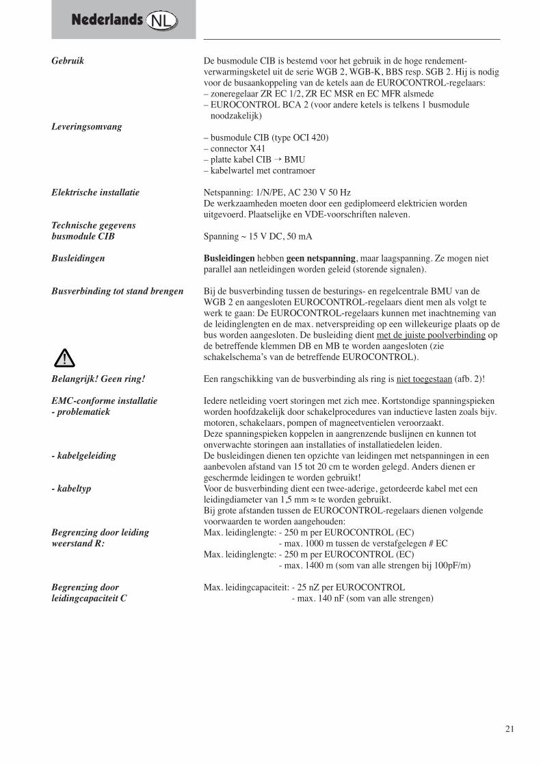
De busmodule CIB is bestemd voor het gebruik in de hoge rendement-verwarmingsketel uit de serie WGB 2, WGB-K, BBS resp. SGB 2. Hij is nodigvoor de busaankoppeling van de ketels aan de EUROCONTROL-regelaars:– zoneregelaar ZR EC 1/2, ZR EC MSR en EC MFR alsmede – EUROCONTROL BCA 2 (voor andere ketels is telkens 1 busmodule
noodzakelijk)
– busmodule CIB (type OCI 420)– connector X41– platte kabel CIB → BMU– kabelwartel met contramoer
Netspanning: 1/N/PE, AC 230 V 50 HzDe werkzaamheden moeten door een gediplomeerd elektricien wordenuitgevoerd. Plaatselijke en VDE-voorschriften naleven.
Spanning ~ 15 V DC, 50 mA
Busleidingen hebben geen netspanning, maar laagspanning. Ze mogen nietparallel aan netleidingen worden geleid (storende signalen).
Bij de busverbinding tussen de besturings- en regelcentrale BMU van deWGB 2 en aangesloten EUROCONTROL-regelaars dient men als volgt tewerk te gaan: De EUROCONTROL-regelaars kunnen met inachtneming vande leidinglengten en de max. netverspreiding op een willekeurige plaats op debus worden aangesloten. De busleiding dient met de juiste poolverbinding opde betreffende klemmen DB en MB te worden aangesloten (zieschakelschema’s van de betreffende EUROCONTROL).
Een rangschikking van de busverbinding als ring is niet toegestaan (afb. 2)!
Iedere netleiding voert storingen met zich mee. Kortstondige spanningspiekenworden hoofdzakelijk door schakelprocedures van inductieve lasten zoals bijv.motoren, schakelaars, pompen of magneetventielen veroorzaakt. Deze spanningspieken koppelen in aangrenzende buslijnen en kunnen totonverwachte storingen aan installaties of installatiedelen leiden.De busleidingen dienen ten opzichte van leidingen met netspanningen in eenaanbevolen afstand van 15 tot 20 cm te worden gelegd. Anders dienen ergeschermde leidingen te worden gebruikt!Voor de busverbinding dient een twee-aderige, getordeerde kabel met eenleidingdiameter van 1,5 mm ≈ te worden gebruikt. Bij grote afstanden tussen de EUROCONTROL-regelaars dienen volgendevoorwaarden te worden aangehouden: Max. leidinglengte: - 250 m per EUROCONTROL (EC)
- max. 1000 m tussen de verstafgelegen # EC Max. leidinglengte: - 250 m per EUROCONTROL (EC)
- max. 1400 m (som van alle strengen bij 100pF/m)
Max. leidingcapaciteit: - 25 nZ per EUROCONTROL- max. 140 nF (som van alle strengen)
Nederlands NL
22
ketel WGB 2 CIB
zoneregelaar EC 1/2
ketel 2
ketel 3
ketel 4
alte
rnat
ief
ketel 1
zoneregelaar EC 1/2
busmoduleCIB
zoneregelaar EC MSR
zoneregelaar EC 1/2
zoneregelaar EC 1/2
zoneregelaar EC 1/2
zoneregelaar EC MSR
busmoduleCIB
busmoduleCIB
busmoduleCIB
EC BCA 2
zoneregelaar EC MSR
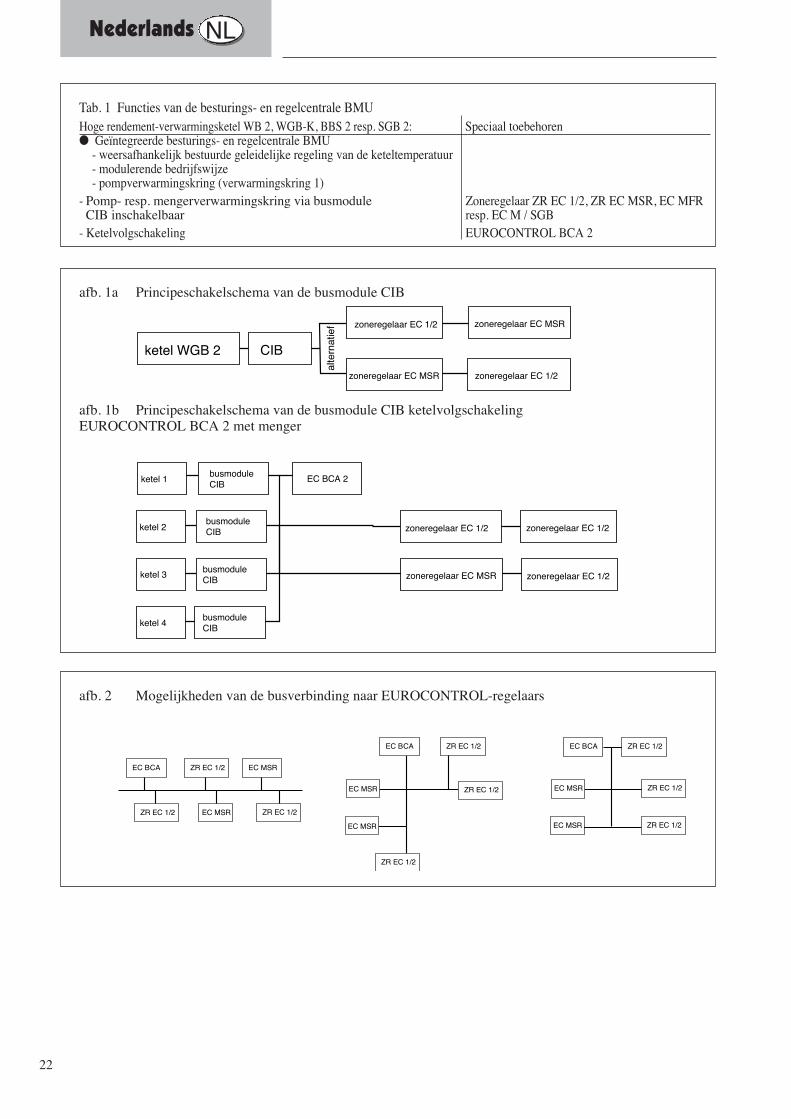
afb. 1a Principeschakelschema van de busmodule CIB
afb. 1b Principeschakelschema van de busmodule CIB ketelvolgschakeling EUROCONTROL BCA 2 met menger
EC BCA ZR EC 1/2
ZR EC 1/2
EC MSR
EC MSR
EC BCA ZR EC 1/2
ZR EC 1/2EC MSR
EC BCA ZR EC 1/2
ZR EC 1/2
EC MSRZR EC 1/2
ZR EC 1/2EC MSR
EC MSR
ZR EC 1/2
afb. 2 Mogelijkheden van de busverbinding naar EUROCONTROL-regelaars
Tab. 1 Functies van de besturings- en regelcentrale BMU Hoge rendement-verwarmingsketel WB 2, WGB-K, BBS 2 resp. SGB 2: Speciaal toebehoren● Geïntegreerde besturings- en regelcentrale BMU
- weersafhankelijk bestuurde geleidelijke regeling van de keteltemperatuur- modulerende bedrijfswijze- pompverwarmingskring (verwarmingskring 1)
- Pomp- resp. mengerverwarmingskring via busmodule Zoneregelaar ZR EC 1/2, ZR EC MSR, EC MFR CIB inschakelbaar resp. EC M / SGB
- Ketelvolgschakeling EUROCONTROL BCA 2
Nederlands NL

23
Nederlands NL
Voor de montage de installatie stroomloos maken. ● De ketelvoorwand van de WGB 2 verwijderen en het ketelschakelvelduitklappen. Na het verwijderen van de schakelveldachterwand wordt deinbouwlocatie van de busmodule CIB toegankelijk. ● Busmodule CIB op de besturings- en regelcentrale BMU latenvastklikken en 6-pol. platte kabel op de connector X40 van de BMU steken(afb. 3). Opdat de zoneregelaars resp. EUROCONTROL met de hoge rendement-verwarmingsketels kunnen communiceren, dient er een 2-pol. leiding(bouwzijdig) van de busmodule CIB naar de regelaars te worden gelegd. ● Aan de busmodule CIB dient de 2-pol. leiding aan de stekker X41, klem1 en 2 (massa) en aan de regelaars, klemmen DB en MB met de juistepoolaansluiting te worden aangesloten:anzuschließen:
klem 1 aan DBklem 2 aan MB
Nadat de aansluiting tot stand is gebracht dienen de instellingen voor debusmodule aan de besturings- en regelcentrale BMU alsmede deinstellingen van de zoneregelaars aan de betreffende zoneregelaars teworden uitgevoerd! Hiervoor dient de BMU door middel van het ruimteregelapparaat RRGresp. de servicemodule RRG (toebehoren) volgens de nevenstaande tabel 2te worden ingesteld. De busleiding moet met de bijgevoegde kabelschroefverbinding (metgeïntegreerde trekontlasting) door de in de ketelbodem aanwezige boringworden geleid en worden vastgezet. Verder dient de leiding in eentrekontlasting van het schakelveld te worden vastgezet. De kabelwartel dient door middel van nakomen van de afdichtingnorm IPX4Den op grond van de voorgeschreven luchtdichte afdichting van de luchtkamervast aan te draaien, zodat de afdichtring de busleiding goed afdicht. .Na het openen van de ketel dienen, om de contactbeveiliging veilig testellen, de vast te schroeven ommantelingscomponenten weer met debetreffende schroeven te worden bevestigd
Bij de ingebruikname dient de gebruiksaanwijzing van de ketel in acht teworden genomen!
Busmodule CIB monteren
Busleiding en #zu-naar ?#zoneregelaars tot stand brengen
Aanwijzing m.b.t. de instelling vande busmodule CIB
Vastzetten in trekontlastingen
Afdichtingsnorm IPX4D
Contactbeveiligin
Ingebruikname
Kesselschalfeld
Steuer- und Regelzentrale (BMU)
Busmodul CIB
afb. 3 Montage van de busmodule CIB (ketelschakelveld in uitgeklapte toestand)
busmodule CIB
besturings- en regelcentrale BMU
ketelschakelveld
24
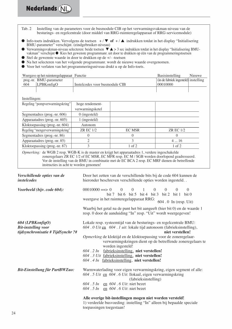
Door het zetten van de verschillende bits bij de code 604 kunnen dehieronder beschreven verschillende opties worden ingesteld. .
00010000 ==> 0 0 0 1 0 0 0 0bit 7 bit 6 bit 5 bit 4 bit 3 bit 2 bit 1 bit 0
weergave in het ruimteregelapparaat RRG: 604 . 0 In (resp. Uit)
Waarbij het getal na de punt het bit aangeeft (hier bit 0) en de waarde 1resp. 0 door de aanduiding “In” resp. “Uit” wordt weergegeven!
Lokale resp. systeemtijd van de besturings- en regelcentrale BMU: 604 . 0 Uit en 604 . 1 uit: lokale tijd autonoom (fabrieksinstelling),
niet verstellen!Opmerking de kloktijd en de kloktoepassing voor de zoneregelaar-
verwarmingskringen dient op de betreffende zoneregelaars teworden ingesteld!
604 . 2 In fabrieksinstelling, niet verstellen!604 . 3 Uit fabrieksinstelling, niet verstellen!604 . 4 In fabrieksinstelling, niet verstellen!
Warmwaterlading voor eigen verwarmingskring, eigen segment of alle: 604 . 5 Uit en 604 . 6 Uit: llokaal, eigen verwarmingskring
(fabrieksinstelling)604 . 5 In en 604 . 6 Uit: niet bezet604 . 5 In en 604 . 6 Uit: niet bezet
Alle overige bit-instellingen mogen niet worden versteld!1) verdeelde busvoeding: instelling “In” alleen bij bepaalde specialetoepassingen toegestaan!
Verschillende opties van deinstelcodes
Voorbeeld (bijv. code 604):
604 (LPBKonfigO)Bit-instelling voortijdsynchronisatie # TijdSynchr ?#
Bit-Einstellung für PartBWZuo:
Tab. 2 Instelling van de parameters voor de busmodule CIB op het verwarmingsvakman-niveau van debesturings- en regelcentrale (door middel van RRG-ruimteregelapparaat of RRG-servicemodule)
● Info-toets indrukken. Vervolgens de toetsen + / ▼ of + / ▲ indrukken totdat in het display “InitialiseringBMU-parameter” verschijnt. (eindgebruiker-niveau)
● Verwarmingsvakman-niveau selecteren: beide toetsen ▼ ▲ > 3 sec indrukken totdat in het display “Initialisering BMU-vakman” verschijnt ● Kies het gewenste programmanr. uit door te drukken op één van de programmeringstoetsen
● Stel de gewenste waarde in door te drukken op de +/- -toetsen● Na het selecteren van het volgende programmanr. wordt de nieuwe waarde overgenomen. ● Voor het verlaten van het programmeringsniveau drukt u op de Info-toets.
Weergave op het ruimteregelapparaat Functie Basisinstelling Nieuweprog.-nr. BMU-parameter (in de fabriek ingesteld) instelling604 LPBKonfigO Instelcodes voor busmodule CIB 00010000
Instellingen:Regeling “pompverwarmingskring” hoge rendement-
verwarmingsketelSegmentadres (prog.-nr. 606) 0 (ingesteld)Apparaatadres (prog.-nr. 605) 1 (ingesteld)Kloktoepassing (prog.-nr. 604) AutonomRegeling “mengerverwarmingskring” ZR EC 1/2 EC MSR ZR EC 1/2 Segmentadres (prog.-nr. 86) 0 0 0Apparaatadres (prog.-nr. 85) 2 3 4 ... 16Kloktoepassing (prog.-nr. 87) 3 1 of 2 1 of 2
Opmerking: de WGB 2 resp. WGB-K is de master en krijgt het apparaatadres 1, verdere ingeschakeldezoneregelaars ZR EC 1/2 of EC MSR, EC MFR resp. EC M / SGB worden doorlopend geadresseerd.Vor de instelling van de BMU in combinatie met de EC BCA 2 resp. EC MRF dienen de betreffendeinstructies in acht te worden genomen!
Nederlands NL
25
Nederlands NL
K1Busmodul CIB
K1
1 2
X40 X10 X11
X10-04 X10-05 X10-06
1 2 1 2 1 2 1 21 2 1 2
X10-01 X10-02 X10-03
F4
123456789101112
1 2
B2.1
1 2
1 2
B2.2
1 2
rt rs vi or or
- ++
N1 Steuer- und Regelzentrale BMU (Typ LMU 64.002A100)
X41
X42 OCI 420
LPB-BUS
DB MB
59-272029.4
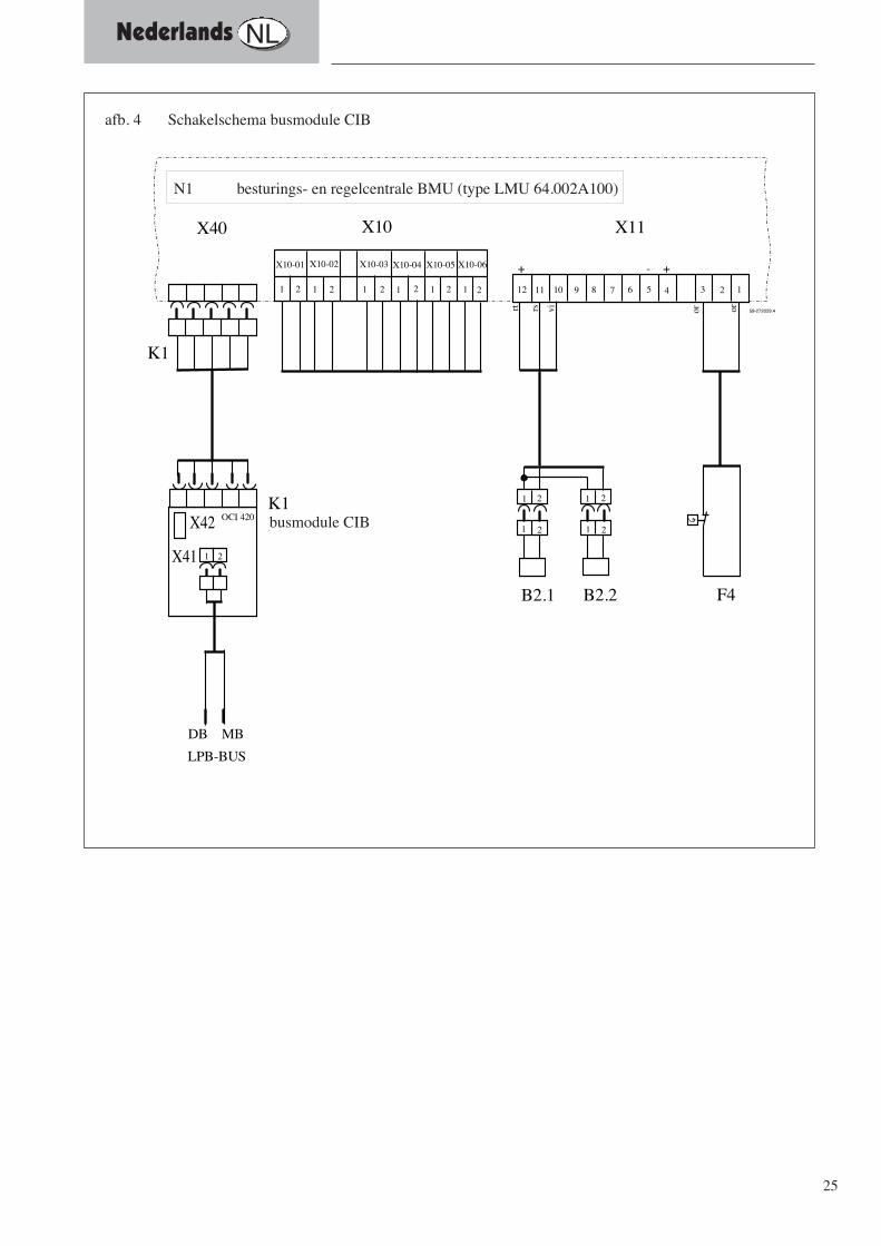
afb. 4 Schakelschema busmodule CIB
N1 besturings- en regelcentrale BMU (type LMU 64.002A100)
busmodule CIB
26
Italiano I
I lavori devono essere eseguiti da un tecnico qualificato.
Importanti avvertenze per il montaggio, l’uso, la taratura e lamanutenzione vengono contrassegnate con questo simbolo.
Osservare le tavole di taratura di queste istruzioni e le tavole di taraturadelle caldaie a condensazione WGB2, WGB-K!
Avvertenze generali sulla sicurezza
Installazione elettrica:
Avvertenza importante:
Prima messa in funzione:
27
Italiano I
Applicazione
Stato di fornitura
Allacciamento elettrico
Dati tecnicimodulo Bus CIB
Cavi bus
Produzione del collegamento Bus
Importante! nessun anello!
Installazione EMV esatta- problematica
- conduzione cavi
- tipo cavi
Limite dovuto all’impedenza delcavo R:limite dovuto alla capienza cavo C:
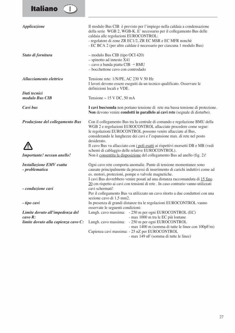
Il modulo Bus CIB è previsto per l’impiego nella caldaia a condensazionedella serie WGB 2, WGB-K. E’ necessario per il collegamento Bus dellecaldaia alle regolazioni EUROCONTROL:- regolatore di zone ZR EC1/2, ZR EC MSR e EC MFR nonchè- EC BCA 2 (per altre caldaie è necessario per ciascuna 1 modulo Bus)
– modulo Bus CIB (tipo OCI 420)– spinotto ad innesto X41– cavo a banda piatta CIB → BMU– bocchettone cavo con controdado
Tensione rete: 1/N/PE, AC 230 V 50 HzI lavori devono essere eseguiti da un tecnico qualificato. Osservare ledefinizioni locali e VDE.
Tensione ~ 15 V DC, 50 mA
I cavi bus/sonda non portano tensione di rete ma bassa tensione di protezione.Non devono venire condotti in parallelo ai cavi rete (segnale di disturbo).
Con il collegamento Bus tra la centrale di comando e regolazione BMU dellaWGB 2 e regolazioni EUROCONTROL allacciate procedere come segue:le regolazioni EUROCONTROL possono venire allacciate al Bus,considerando le lunghezze dei cavi e l’espansione max. di rete nel postodesiderato.Il cavo Bus va allacciato con i poli esatti ai rispettivi morsetti DB e MB (vedischemi di cablaggio delle relative EUROCONTROL).Non è consentita la disposizione del collegamento Bus ad anello (fig. 2)!
Ogni cavo rete comporta anomalie. Punte di tensione momentanee sonocausate principalmente da processi di inserimento di carichi induttivi come ades. motori, protezioni, pompe o valvole magnetiche.I cavi Bus dovrebbero venire posati ad una distanza raccomandata di 15 fino20 cm rispetto ai cavi con tensioni di rete . In caso contrario vanno utilizzaticavi schermati!Per il collegamento Bus va utilizzato un cavo ritorto a due conduttori con unasezione cavo di 1,5 mm2.In presenza di grandi distanze tra le regolazioni EUROCONTROL vannoosservate le seguenti condizioni:Lungh. cavo massima: - 250 m per ogni EUROCONTROL (EC)
- max 1000 m tra le EC più lontaneLungh. cavo massima: - 250 m per ogni EUROCONTROL
- max 1400 m (somma di tutte le linee con 100pF/m)Capienza cavi massima: - 25 nZ per EUROCONTROL
- max 149 nF (somma di tutte le linee)

28
Kessel WGB 2 CIB
Zonenregler EC 1/2
Kessel 2
Kessel 3
Kessel 4
alte
rnat
iv
Kessel 1
Zonenregler EC 1/2
BusmodulCIB
Zonenregler EC MSR
Zonenregler EC 1/2
Zonenregler EC 1/2
Zonenregler EC 1/2
Zonenregler EC MSR
BusmodulCIB
BusmodulCIB
BusmodulCIB
EC BCA 2
Zonenregler EC MSR
Fig. 1 quadro principio inserimento del modulo Bus CIB
Fig. 1 b quadro principio inserimento del modulo Bus CIB sequenza caldaiaEUROCONTROL BCA 2 con miscelatore
EC BCA ZR EC 1/2
ZR EC 1/2
EC MSR
EC MSR
EC BCA ZR EC 1/2
ZR EC 1/2EC MSR
EC BCA ZR EC 1/2
ZR EC 1/2
EC MSRZR EC 1/2
ZR EC 1/2EC MSR
EC MSR
ZR EC 1/2
Fig. 2 Possibilità del collegamento Bus alle regolazioni EUROCONTROL
Tab. 1 funzioni della centrale di comando e regolazione BMU
Caldaia a condensazione WGB 2 o WGB-K: Accessori a parte● Centrale di comando e regolazione integrata BMU
- regolazione scorrevole climatica della temperatura di caldaia- tipo d’esercizio modulante- circuito riscaldamento diretto (circuito riscald.)
- possibilità di inserire un circuito riscaldamento diretto o miscelatotramite modulo Bus CIB regolatore di zone ZR EC 1/2, ZR EC MSR bzw. EC MFR
- sequenza caldaie EUROCONTROL BCA 2
regolatore di zone EC1/2al
tern
ativ
e
regolatore di zone EC1/2
regolatore di zone EC1/2 regolatore di zone EC1/2
regolatore di zone EC1/2
regolatore di zone EC MSR
regolatore di zone EC MSR
modulo Bus CIB EC BCA 2Caldaia 1
Caldaia 2
Caldaia 3
Caldaia 4
modulo Bus CIB
modulo Bus CIB
modulo Bus CIB
regolatore di zone EC MSR
Caldaia WGB 2 CIB
29
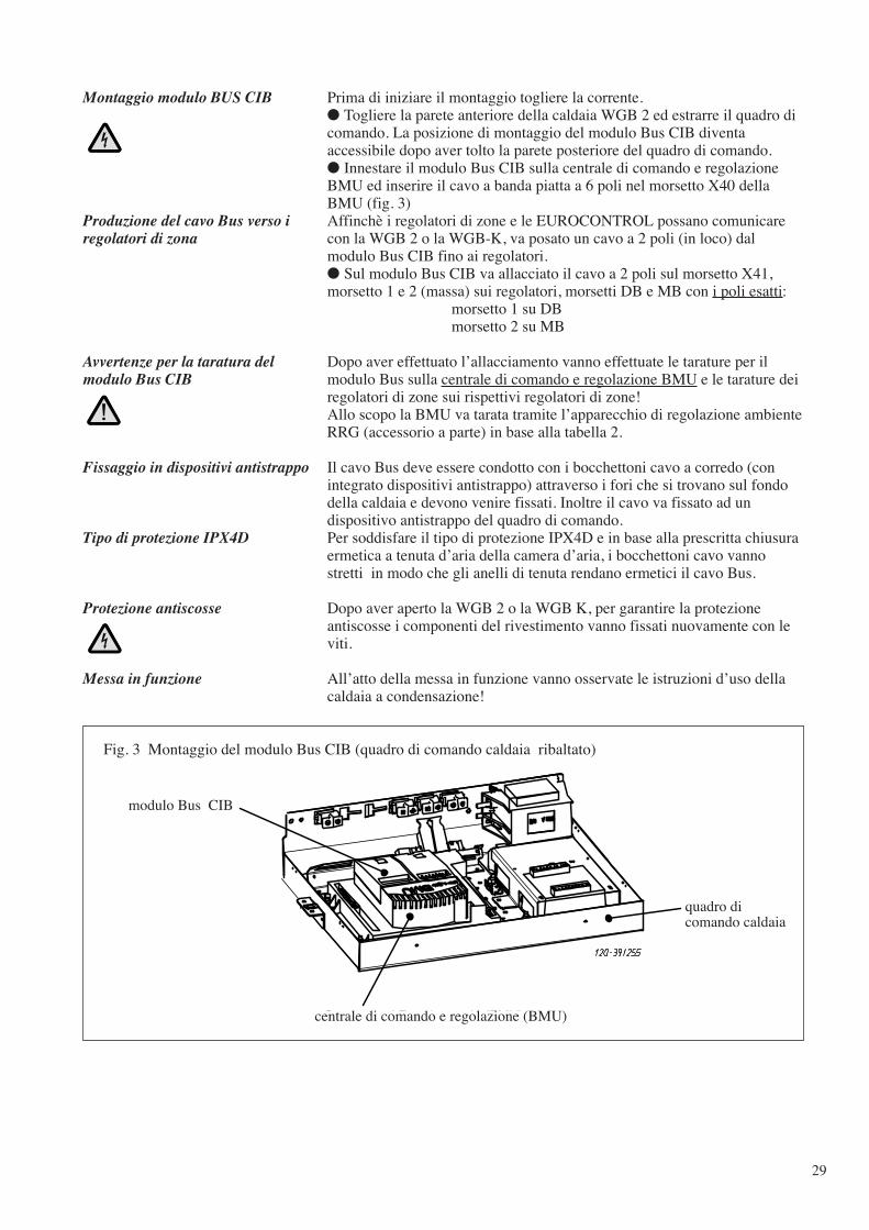
Prima di iniziare il montaggio togliere la corrente.● Togliere la parete anteriore della caldaia WGB 2 ed estrarre il quadro dicomando. La posizione di montaggio del modulo Bus CIB diventaaccessibile dopo aver tolto la parete posteriore del quadro di comando.● Innestare il modulo Bus CIB sulla centrale di comando e regolazioneBMU ed inserire il cavo a banda piatta a 6 poli nel morsetto X40 dellaBMU (fig. 3)Affinchè i regolatori di zone e le EUROCONTROL possano comunicarecon la WGB 2 o la WGB-K, va posato un cavo a 2 poli (in loco) dalmodulo Bus CIB fino ai regolatori.● Sul modulo Bus CIB va allacciato il cavo a 2 poli sul morsetto X41,morsetto 1 e 2 (massa) sui regolatori, morsetti DB e MB con i poli esatti:
morsetto 1 su DBmorsetto 2 su MB
Dopo aver effettuato l’allacciamento vanno effettuate le tarature per ilmodulo Bus sulla centrale di comando e regolazione BMU e le tarature deiregolatori di zone sui rispettivi regolatori di zone!Allo scopo la BMU va tarata tramite l’apparecchio di regolazione ambienteRRG (accessorio a parte) in base alla tabella 2.
Il cavo Bus deve essere condotto con i bocchettoni cavo a corredo (conintegrato dispositivi antistrappo) attraverso i fori che si trovano sul fondodella caldaia e devono venire fissati. Inoltre il cavo va fissato ad undispositivo antistrappo del quadro di comando.Per soddisfare il tipo di protezione IPX4D e in base alla prescritta chiusuraermetica a tenuta d’aria della camera d’aria, i bocchettoni cavo vannostretti in modo che gli anelli di tenuta rendano ermetici il cavo Bus.
Dopo aver aperto la WGB 2 o la WGB K, per garantire la protezioneantiscosse i componenti del rivestimento vanno fissati nuovamente con leviti.
All’atto della messa in funzione vanno osservate le istruzioni d’uso dellacaldaia a condensazione!
Montaggio modulo BUS CIB
Produzione del cavo Bus verso iregolatori di zona
Avvertenze per la taratura delmodulo Bus CIB
Fissaggio in dispositivi antistrappo
Tipo di protezione IPX4D
Protezione antiscosse
Messa in funzione
Kesselschalfeld
Steuer- und Regelzentrale (BMU)
Busmodul CIB
Fig. 3 Montaggio del modulo Bus CIB (quadro di comando caldaia ribaltato)
modulo Bus CIB
quadro dicomando caldaia
centrale di comando e regolazione (BMU)
30
Inserendo i vari bits con codice 604 possono venire impostate le seguentidifferenti opzioni descritte.
00010000 ==> 0 0 0 1 0 0 0 0Bit 7 Bit 6 Bit 5 Bit 4 Bit 3 Bit 2 Bit 1 Bit 0
Indicazione nell’apparecchio di regolazione ambiente RRG:604 . 0 Inserito (o disinserito)
In cui la cifra dopo il punto indica il bit (qui bit 0) ed il valore 1 o 0 vienerappresentato dalla scritta “inserito” o “disinserito”!
Tempo locale rispett. sistema della centrale di comando e regolazione BMU:604 . 0 Aus e 604 . 1 Aus: tempo locale autonomo (taratura in fabbrica)Avvertenza: L’ora esatta e l’esercizio orologio per i circuiti di riscaldamento
– regolatori di zone va impostato sui rispettivi regolatori dizone!
604 . 0 Ein e 604 . 1 Aus: non posato604 . 0 Aus e 604 . 1 Ein: non posato604 . 0 Ein e 604 . 1 Ein: libero
Carico acqua sanitaria per circuito riscaldamento proprio, propriosegmento o tutti:604 . 5 Aus e 604 . 6 Aus: locale, circuito riscald. proprio (taratura in
fabbrica)604 . 5 Ein e 604 . 6 Aus: non posato604 . 5 Ein e 604 . 6 Aus: non posato
Diverse opzioni dei codici ditaratura
Esempio (ad es. codice 604):
604 (LPBKonfig0)Impostazione Bit per ZeitSynchr:
Taratura Bit per PartBWZuo:
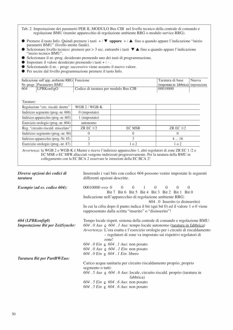
Tab. 2 Impostazione dei parametri PER IL MODULO Bus CIB nel livello tecnico della centrale di comando eregolazione BMU (tramite apparecchio di regolazione ambiente RRG o modulo service RRG).
● Premere il tasto Info. Quindi premere i tasti + / ▼ oppure + / ▲ fino a quando appare l’indicazione “inizioparametri BMU” (livello utente finale).
● Selezionare livello tecnico: premere per > 3 sec. entrambi i tasti ▼ ▲ fino a quando appare l’indicazione“inizio tecnico BMU”.
● Selezionare il nr.-prog. desiderato premendo uno dei tasti di programmazione.● Impostare il valore desiderato premendo i tasti + / - .● Selezionando il nr. - progr. successivo viene assunto il nuovo valore.● Per uscire dal livello programmazione premere il tasto Info.
Indicazione sull’app. ambiente RRG Funzione Taratura di base Nuova Nr.-progr. Parametro BMU (impostata in fabbrica) impostazione604 LPBKonfigO Codice di taratura per modulo Bus CIB 00010000
Tarature:Regolazione “circ. riscald. diretto” WGB 2 / WGB-KIndirizzo segmento (prog.-nr. 606) 0 (impostato)Indirizzo apparecchio (prog.-nr. 605) 1 (impostato)Esercizio orologio (prog.-nr. 604) autonomoReg. “circuito riscald. miscelato” ZR EC 1/2 EC MSR ZR EC 1/2 Indirizzo segmento (prog.-nr. 86) 0 0 0Indirizzo apparecchio (prog.-Nr. 85) 2 3 4 ... 16Esercizio orologio (prog.-nr. 87) 3 1 o 2 1 o 2
Avvertenza: la WGB 2 o WGB-K è Master e riceve l’indirizzo apparecchio 1, altri regolatori di zone ZR EC 1 /2 oEC MSR o EC MFR allacciati vengono indirizzati progressivamente. Per la taratura della BMU incollegamento con la EC BCA 2 osservare le istruzioni della EC BCA 2!
31
K1Busmodul CIB
K1
1 2
X40 X10 X11
X10-04 X10-05 X10-06
1 2 1 2 1 2 1 21 2 1 2
X10-01 X10-02 X10-03
F4
123456789101112
1 2
B2.1
1 2
1 2
B2.2
1 2
rt rs vi or or
- ++
N1 Steuer- und Regelzentrale BMU (Typ LMU 64.002A100)
X41
X42 OCI 420
LPB-BUS
DB MB
59-272029.4
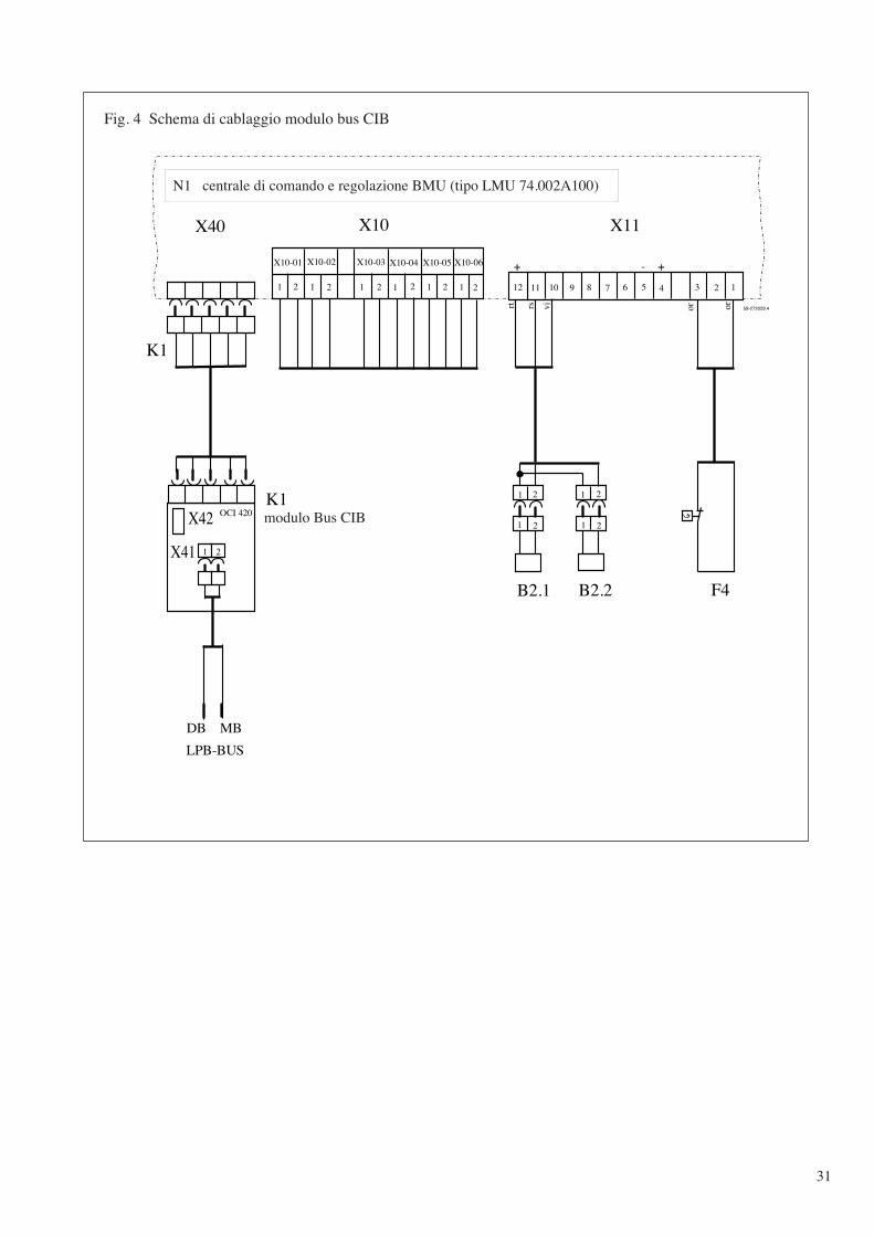
Fig. 4 Schema di cablaggio modulo bus CIB
N1 centrale di comando e regolazione BMU (tipo LMU 74.002A100)
modulo Bus CIB
32
Notizen/Notes/Notices/Nota
33
Notizen/Notes/Notices/Nota
34
59-2
72 0
57.4
10.
02 R
Deutschland: AUGUST BRÖTJE GmbHPostfach 1354 · D-26171 Rastede · Tel. (04402) 80-0 · Telefax 80 583
UK: POTTERTON COMMERCIALRegistered Office: Pentagon House, Sir Frank Whittle Road, Derby DE21 4XARegistered in England No. 3879156
France: BAXI France Sa 157, Avenue Charles Floquet · F-93158 Le Blanc Mesnil CedexTéléphone 0145915973 · Fax 0145915971 · e-mail: [email protected]
Belgium: BAXI Belgium Sa 23, Parc Industriel · B-1440 Wauthier-BraineTel.: 02 / 366 04 00 · Fax 02 / 366 06 85
Italia: MANZARDO S.p.A.I-39100 Bolzano · Via C. Augusta, 18 · Tel. (0471) 285646 · Fax (0471) 284129 · Tlx 400267