Modell der Elektrolokomotive Gea 2/4 24440 · Lok wurde dann als Gea 2/4 bezeichnet. Das LGB Modell...
24
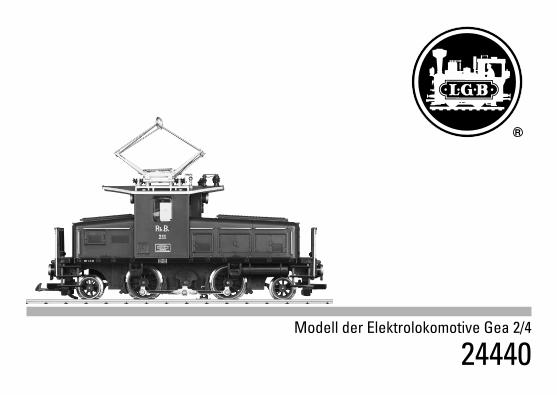
Modell der Elektrolokomotive Gea 2/4 24440
Transcript of Modell der Elektrolokomotive Gea 2/4 24440 · Lok wurde dann als Gea 2/4 bezeichnet. Das LGB Modell...
Modell der Elektrolokomotive Gea 2/4
24440
2
Das Vorbild Die Rhätische Bahn beschaffte 1913 sieben kleine Elloks für die Engadin-Strecke von St. Moritz nach Scuol. Diese Loks erhielten die Bezeichnung „Ge 2/4” und die Nummern 201-207. Um einen dampflosen Rangierbetrieb in den Bahnhöfen Chur und Landquart zu ermöglichen, wurden zwischen 1943 und 1946 drei Elektrolokomotiven des Typs Ge 2/4 auf Mittelführerstand (sog. Bügeleisen) umgebaut und auch umgezeichnet. Durch die Gewichtsersparnis konnte bei Lok 211 sogar eine Akku-Batterieanlage eingebaut werden. Die Lok wurde dann als Gea 2/4 bezeichnet. Das LGB Modell 24440 gibt diese Lok vorbildgerecht wieder.
The Prototype In 1913, Switzerland’s Rhätische Bahn (RhB) purchased seven light electric locomotives for the Engadin line from St. Moritz to Scuol. These “Ge 2/4“ locos were numbered 201 to 207. Between 1943 and 1946 three class Ge 2/4 electric locomo-tives with a center cab (so-called „flat irons“) were rebuilt and given a new class number in order to have steam-free switching operations at the stations in Chur and Landquart. The savings in weight also made it possible to install a storage battery layout in road number 211. This locomotive was then designated as the class Gea 2/4. The 24440 LGB model is a prototypical reproduction of this locomotive.
3
Le Prototype Le Chemin de fer Rhétique a acquit en 1913 sept petites locomotives électriques pour la ligne de l’Engadine, de St-Moritz à Scuol. Ces locomotives ont été appelées «Ge 2/4» et reçurent les numéros 201-207. Afin d’assurer un fonctionnement sans vapeur dans les gares de Chur et Landquart, trois locomotives électriques de type Ge 2/4 ont été conçues entre 1943 et 1946 (fers à repas-ser). Grâce au gain en matière de poids, la locomotive 211 a pu être équipée d’un système de batterie. La locomotive a ensuite été appelée Gea 2/4. Le modèle LGB 24440 représente cette locomotive.
Inhaltsverzeichnis: SeiteSicherheitshinweise 4Wichtige Hinweise 4Funktionen 4Betriebshinweise 4Wartung und Instandhaltung 5Bilder 16Ersatzteile 18
Table of Contents: Page Safety Notes 8Important Notes 8Functions 8Information about operation 8Service and maintenance 9Figures 16 Spare Parts 18
Sommaire : PageRemarques importantes sur la sécurité 12Information Importante 12Fonctionnement 12Remarques sur l’exploitation 12Entretien et maintien 13Images 16 Pièces de rechange 18
4
Sicherheitshinweise• DasModelldarfnurmiteinemdafürbestimmtenBe-
triebssystem eingesetzt werden. • NurSchaltnetzteileundTransformatorenverwenden,die
Ihrer örtlichen Netzspannung entsprechen.• DasModelldarfnurauseinerLeistungsquelleversorgt
werden. • BeachtenSieunbedingtdieSicherheitshinweiseinder
Bedienungsanleitung zu Ihrem Betriebssystem. • NichtfürKinderunter15Jahren.• ACHTUNG!FunktionsbedingtescharfeKantenundSpitzen.Wichtige Hinweise• DieBedienungsanleitungistBestandteildesProduktes
und muss deshalb aufbewahrt sowie bei Weitergabe des Produktes mitgegeben werden.
• FürReparaturenoderErsatzteilewendenSiesichbitteanIhren LGB-Fachhändler.
• http://www.maerklin.com/en/imprint.htmlFunktionen • DasModellistfürdenBetriebaufLGB-Zweileiter-Gleich-
strom-Systemen mit herkömmlichen LGB-Gleichstrom-Fahrpulten vorgesehen (DC, 0 - 24 V).
• VerwendenSiefürdiesesModelleinFahrgerätmitmehrals 1 A Fahrstrom.
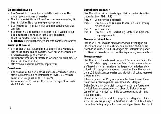
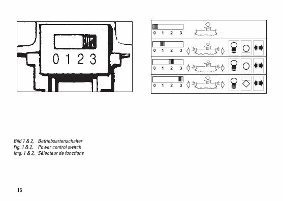
Betriebsartenschalter Das Modell hat einen vierstufigen Betriebsarten-Schalter unter der Lok (Bild 1 & 2). Pos. 0 Lok stromlos abgestellt Pos. 1 Strom aus den Gleisen, Motor und Beleuchtung
eingeschaltetPos. 2 wie Position 1Pos. 3 Strom aus der Oberleitung, Motor und Beleuch-
tung eingeschaltet Mehrzweck-Steckdose Das Modell hat jeweils eine Mehrzweck-Steckdose für Flachstecker an beiden Stirnseiten (Bild 3 & 4). Über die Steckdose können Sie LGB-Wagen mit Beleuchtung oder mit Geräuschelektronik an die Gleisspannung anschließen.
MehrzugsystemDas Modell ist bereits werkseitig mit Decoder on board für das LGB-Mehrzugsystem ausgerüstet. Es kann unverändert auf herkömmlichen analogen Anlagen oder mit dem digi-talenMehrzugsystemeingesetztwerden.ZumEinsatzmitdem LGB-Mehrzugsystem ist das Modell auf Lokadresse 03 programmiert. Informationen zum Programmieren der Lokadresse finden SieindenAnleitungendereinzelnenMZS-Regler.Beim Betrieb mit dem Mehrzugsystem können Funktionen der Lok ferngesteuert werden. Über die Beleuchtungs-taste (“9” bei Handys) wird die Lokbeleuchtung ein- und ausgeschaltet. Beim Betrieb mit dem Mehrzugsystem verfügt die Lok über eineLastnachregelung:DieMotordrehzahl(unddamitunternormalen Bedingungen die Geschwindigkeit) wird konstant

5
gehalten, auch wenn sich die Belastung der Lok ändert, z. B. inKurvenoderaufSteigungen.
Stromversorgung aus der OberleitungDiese Lokomotive kann ihren Strom über die LGB-Oberlei-tung erhalten (siehe Betriebsarten). Auf der Unterseite des Modells ist ein roter Punkt. Das Modell so auf die Schienen stellen, daß der rote Punkt zu der Schiene weist, die nicht mit dem Oberleitungs-Trafo verbunden ist.VORSICHT! Eine Oberleitung darf nur im Analogbetrieb zur Stromversorgung verwendet werden. Im Digitalbetrieb mit dem LGB-Mehrzugsystem muß das Fahrzeug aus den Schienen mit Strom versorgt werden, da sonst gefährliche Spannungen entstehen können.
WARTUNG
Schmierung Die Achslager und die Lager des Gestänges hin und wieder mit je einem Tropfen MärklinÖl (7149) ölen.
Austauschen der Glühlampen Lampen (unten): Den Ring außen am Lampenglas entfernen. Vorsichtig das Glas von der Laterne hebeln. Mit einer Pin-zette die eingesteckte Glühlampe aus der Fassung ziehen. Neue Glühlampe einsetzen. Modell wieder zusammenbauen. Lampen (oben): Vorsichtig das Glas von der Laterne hebeln. Mit einer Pinzette die eingesteckte Glühlampe aus der Fassung ziehen. Neue Glühlampe einsetzen. Modell wieder zusammenbauen. Innenbeleuchtung: Glühlampe mit einer Pinzette aus der Fassung ziehen. Neue Glühlampe einstecken. Falls die Glühlampe nur schwer erreichbar ist, lösen Sie die vier Befestigungsschrauben und nehmen Sie das Dach ab.
Austauschen des Haftreifens • SchraubeamTreibradmitHaftreifenlösen.• Treibstangeabnehmen.• MiteinenkleinenflachenSchraubendreherdenaltenHaftreifenentfernen:
• DenaltenHaftreifenausderRille(Nut)imTreibradhebeln.
• VorsichtigdenneuenHaftreifenüberdasRadschiebenund in die Rille (Nut) des Rads einsetzen.
• Überprüfen,daßderHaftreifenrichtigsitzt.• Modellwiederzusammenbauen.
6
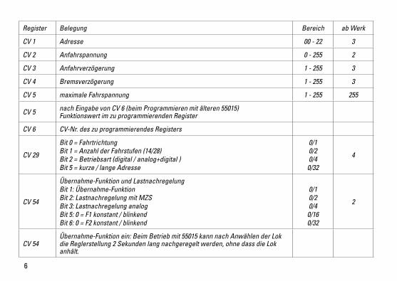
Register Belegung Bereich ab Werk
CV 1 Adresse 00 - 22 3
CV 2 Anfahrspannung 0 - 255 2
CV 3 Anfahrverzögerung 1 - 255 3
CV 4 Bremsverzögerung 1 - 255 3
CV 5 maximale Fahrspannung 1 - 255 255
CV 5 nach Eingabe von CV 6 (beim Programmieren mit älteren 55015) Funktionswert im zu programmierenden Register
CV 6 CV-Nr. des zu programmierendes Registers
CV 29
Bit 0 = Fahrtrichtung Bit 1 = Anzahl der Fahrstufen (14/28) Bit 2 = Betriebsart (digital / analog+digital )Bit 5 = kurze / lange Adresse
0/10/20/4
0/32
4
CV 54
Übernahme-Funktion und Lastnachregelung Bit 1: Übernahme-Funktion Bit 2: Lastnachregelung mit MZS Bit 3: Lastnachregelung analog Bit 5: 0 = F1 konstant / blinkend Bit 6: 0 = F2 konstant / blinkend
0/1 0/2 0/4
0/16 0/32
2
CV 54Übernahme-Funktion ein: Beim Betrieb mit 55015 kann nach Anwählen der Lok die Reglerstellung 2 Sekunden lang nachgeregelt werden, ohne dass die Lok anhält.
7
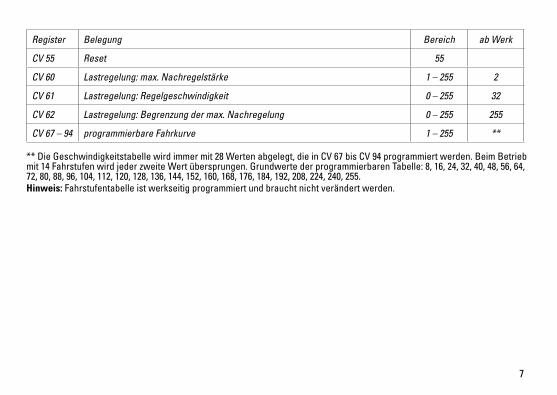
Register Belegung Bereich ab Werk
CV 55 Reset 55
CV 60 Lastregelung: max. Nachregelstärke 1 – 255 2
CV 61 Lastregelung: Regelgeschwindigkeit 0 – 255 32
CV 62 Lastregelung: Begrenzung der max. Nachregelung 0 – 255 255
CV 67 – 94 programmierbare Fahrkurve 1 – 255 **
** Die Geschwindigkeitstabelle wird immer mit 28 Werten abgelegt, die in CV 67 bis CV 94 programmiert werden. Beim Betrieb mit14FahrstufenwirdjederzweiteWertübersprungen.GrundwertederprogrammierbarenTabelle:8,16,24,32,40,48,56,64,72, 80, 88, 96, 104, 112, 120, 128, 136, 144, 152, 160, 168, 176, 184, 192, 208, 224, 240, 255.Hinweis: Fahrstufentabelle ist werkseitig programmiert und braucht nicht verändert werden.

8
Safety Notes• Thislocomotiveistobeusedwiththeoperatingsystem
designed for it. • Useonlyswitchedmodepowersupplyunitsandtransfor-
mers that are designed for your local power system. • Thislocomotivemustneverbesuppliedwithpowerfrom
more than one power pack. • Paycloseattentiontothesafetynotesintheinstructions
for your operating system. • Notforchildrenundertheageof15.• WARNING! Sharp edges and points required for operation.Important Notes• Theoperatinginstructionsareacomponentpartofthe
product and must therefore be kept in a safe place as well as included with the product, if the latter is given to someone else.
• PleaseseeyourauthorizedLGBdealerforrepairsorspare parts.
• http://www.maerklin.com/en/imprint.htmlFunctions• ThismodelisdesignedforoperationonLGBtwo-railDC
systems with conventional LGB DC train controllers or power packs (DC, 0 - 24 volts).
• Usealocomotivecontrollerwithmorethan1ampoftraincurrent for this model.
Mode of Operation Switch This model has a four-way power control switch mounted under the loco (Fig. 1 & 2). Pos. 0 All power off Pos. 1 power from tracks, motor and lights onPos. 2 same as Position 1Pos. 3 power from catenary, motor and lights onMulti-Purpose Socket The model has a “flat“ multi-purpose socket, with a remo-vable cover, on each end wall (Fig. 3 & 4). These sockets can be used to provide track power to cars with lighting or sound electronics.
Multi-Train System The model is equipped with a factory-installed onboard de-coder for the LGB Multi-Train System. It can be used without modifications on analog or digital layouts. For operation with the Multi-Train System, the model is programmed to loco address 03. For information on programming the loco address, see the instructions for various MTS components.When operating with the Multi-Train System, you can remo-tely control the loco’s functions. Press the lighting button (“9” with remotes) to turn the loco lights on or off. When operating with the Multi-Train System, the loco fea-tures a “Back-EMF” function. This keeps the motor speed constant (and under normal conditions the loco speed), even when the load of the loco changes, for example, in curves or on grades.
Catenary Power OperationThis locomotive can be operated with a powered catenary
9
system (see Operating Modes). The bottom of this model is marked with a red dot. Place the model on the track with the red dot pointing to the rail that is not connected to the catenary power supply. CAUTION! This model may be powered with a catenary on analog layouts only. For operation with the digital Multi-Train System, the model must use track power. Otherwise, dangerously high voltages may result.
SERVICE
Lubrication The axle bearings and the side rod ends should be lubrica-ted occasionally with a small amount of Märklin-Öl (7149).
Replacing the light bulbs Lower lights: Remove the ring around the lantern lens. Ca-refully pry the lens away from the lantern. Using tweezers, remove and replace the bulb. Reassemble.Upper lights: Carefully pry the lens away from the lantern. Using tweezers, remove and replace the bulb. Reassemble.Cab light: Using tweezers, remove and replace the bulb. If you have difficulties reaching the light bulb, remove the four screws holding the roof and remove the roof to access the light bulb.
Replacing the traction tire • Removethescrewonthedrivewheelwiththetraction
tire.• Removethesiderodfromthedrivewheel.• Useasmall,straight-bladescrewdrivertoreplacethetractiontire:
• Prytheoldtractiontireoutofthewheelgroove.• Gentlyinsertthenewtractiontireintothewheelgroove.• Makesurethatthetractiontireisseatedproperlyinthe
wheel groove.• Reassemble.
10
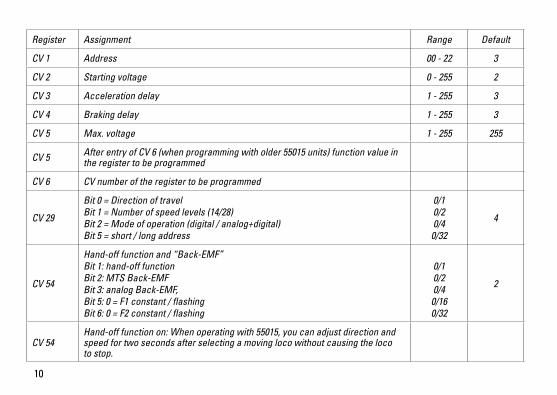
Register Assignment Range Default
CV 1 Address 00 - 22 3
CV 2 Starting voltage 0 - 255 2
CV 3 Acceleration delay 1 - 255 3
CV 4 Braking delay 1 - 255 3
CV 5 Max. voltage 1 - 255 255
CV 5 After entry of CV 6 (when programming with older 55015 units) function value in the register to be programmed
CV 6 CV number of the register to be programmed
CV 29
Bit 0 = Direction of travel Bit 1 = Number of speed levels (14/28) Bit 2 = Mode of operation (digital / analog+digital) Bit 5 = short / long address
0/10/20/4
0/32
4
CV 54
Hand-off function and “Back-EMF” Bit 1: hand-off function Bit 2: MTS Back-EMF Bit 3: analog Back-EMF, Bit 5: 0 = F1 constant / flashing Bit 6: 0 = F2 constant / flashing
0/1 0/2 0/4
0/16 0/32
2
CV 54Hand-off function on: When operating with 55015, you can adjust direction and speed for two seconds after selecting a moving loco without causing the loco to stop.
11
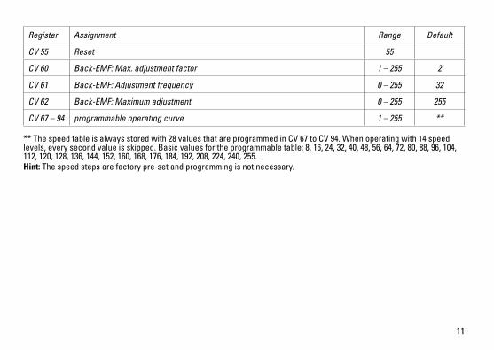
Register Assignment Range Default
CV 55 Reset 55
CV 60 Back-EMF: Max. adjustment factor 1 – 255 2
CV 61 Back-EMF: Adjustment frequency 0 – 255 32
CV 62 Back-EMF: Maximum adjustment 0 – 255 255
CV 67 – 94 programmable operating curve 1 – 255 **
** The speed table is always stored with 28 values that are programmed in CV 67 to CV 94. When operating with 14 speed levels,everysecondvalueisskipped.Basicvaluesfortheprogrammabletable:8,16,24,32,40,48,56,64,72,80,88,96,104,112, 120, 128, 136, 144, 152, 160, 168, 176, 184, 192, 208, 224, 240, 255.Hint: The speed steps are factory pre-set and programming is not necessary.

12
Remarques importantes sur la sécurité• Lalocomotivenepeutêtremiseenservicequ‘avecunsystèmed‘exploitationadéquat.
• Utiliseruniquementdesconvertisseursettransforma-teurs correspondant à la tension du secteur local.
• Lalocomotivenepeutêtrealimentéeencourantqueparune seule source de courant.
• Veuillezimpérativementrespecterlesremarquessurlasécurité décrites dans le mode d’emploi de votre système d’exploitation.
• Neconvientpasauxenfantsdemoinsde15ans.• ATTENTION! Pointes et bords coupants lors du fonction-
nement du produit.Information Importante • Lanoticed‘utilisationfaitpartieintégranteduproduit;
elle doit donc être conservée et, le cas échéant, transmi-se avec le produit.
• Pourtouteréparationouremplacementdepièces,adressez-vous à votre détaillant-spécialiste LGB.
• http://www.maerklin.com/en/imprint.htmlFonctionnement • Lemodèleestprévupourêtreexploitésurdessystèmes
deux rails c.c. LGB avec des pupitres de commandes LGB classiques en courant continu (DC, 0 - 24 V).
• Pourcemodèle,utilisezunrégulateurdemarcheaveccourant moteur supérieur à 1 A.
Commutateur de mode d’exploitation Ce modèle est équipé d’un sélecteur d’alimentation à quatre positions situé sous la locomotive (Img. 1 & 2). Pos. 0 Locomotive hors tension, arrêtée Pos. 1 Alimentation du moteur et de l’éclairage par la voie.Pos. 2 Identique à la position 1Pos. 3 Alimentation du moteur et de l’éclairage par la
ligne à suspension caténaire.Sélecteur de fonctions Il possède deux douilles à usages multiples «plates» avec couvercle amovible situées sur chaque cloison en bout du modèle (Img. 3 & 4). Ces douilles peuvent être utilisées pour fournir l’alimentation électrique de la voie aux voitures munies d’une électronique d’éclairage ou de son.
Système multitrain Ce modèle est équipé d’un décodeur embarqué de série pour le système multitrain LGB. Il peut être utilisé sans modification sur les réseaux analogiques ou numériques. Pour utilisation avec le système multitrain, le modèle réduit est programmé à l’adresse de locomotive 03. Pour des renseignements sur la façon de programmer l’adresse de locomotive, consulter les fiches d’instructions des divers éléments du système multitrain. Les fonctions de la locomotive peuvent être télécommandé-es lorsque cette dernière est utilisée avec le système multitrain. Appuyer sur le bouton d’allumage («9» sur les télécommandes) pour allumer ou éteindre l’éclairage. La locomotive possède une fonction de force contre-élec-tromotrice (FCEM) lorsqu’elle est utilisée avec le système multitrain. Cette fonction permet de conserver constante
13
la vitesse du moteur (ainsi que la vitesse de la locomotive en conditions normales), même lorsque la charge de la locomotive change, comme par exemple en virage ou sur une pente.
Alimentation par ligne à suspension caténaire Cette locomotive peut être alimentée par une ligne à sus-pension caténaire (voir Modes opératoires). Un point rouge se trouve à la partie inférieure du modèle réduit. Placer le modèle réduit sur les rails avec le point rouge dirigé vers le rail qui n’est pas raccordé à la ligne à suspension caténaire. Conseil : Pour déplacer plusieurs trains sur la même voie, nous recommandons d’utiliser le système multitrain (voir Système multitrain). Avec le système multitrain, vous pouvez utiliser une ligne à suspension caténaire non alimentée pour faire plus vrai que vrai.
ENTRETIEN
Lubrification Les roulements des essieux et les articulations des bielles d‘accouplementdoiventêtrelubrifiésdetempsàautreavecune goutte d’huile Märklin (7149).
Remplacement des ampoules Feux inférieurs : Déposer l’anneau de la lentille de la lanter-ne. Sortir avec précaution la lentille de la lanterne. À l’aide de pincettes, enlever et remplacer l’ampoule. Remonter le tout. Feux supérieurs : Sortir avec précaution la lentille de la lan-terne. À l’aide de pincettes, enlever et remplacer l’ampoule. Remonter le tout. Éclairage de la cabine : Enlever et remplacer l’ampoule en utilisant des pincettes. S’il s’avère difficile d’atteindre l’ampoule, enlever les quatre vis de retenue du toit et dépo-ser le toit pour accéder à l’ampoule.
Remplacement du pneu de traction • Enleverlavisdelarouemotriceéquipéedupneude
traction. • Déposerlabielled’accouplementdelarouemotrice.• Utiliserunpetittournevisàlamedroitepourremplacerlepneudetraction:
• Sortiravecprécautionlevieuxpneudelagorgedelaroue.• Placeravecprécautionlepneuneufdanslagorgedelaroue.• S’assurerquelepneudetractionestbienassisdansla
gorge de la roue.• Remonterletout.
14
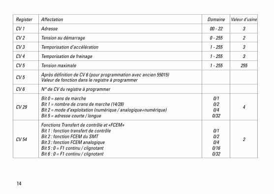
Register Affectation Domaine Valeur d’usine
CV 1 Adresse 00 - 22 3
CV 2 Tension au démarrage 0 - 255 2
CV 3 Temporisation d‘accélération 1 - 255 3
CV 4 Temporisation de freinage 1 - 255 3
CV 5 Tension maximale 1 - 255 255
CV 5 Après définition de CV 6 (pour programmation avec ancien 55015) Valeur de fonction dans le registre à programmer
CV 6 N° de CV du registre à programmer
CV 29
Bit 0 = sens de marche Bit 1 = nombre de crans de marche (14/28) Bit 2 = mode d’exploitation (numérique / analogique+numérique)Bit 5 = adresse courte / longue
0/10/20/4
0/32
4
CV 54
Fonctions Transfert de contrôle et «FCEM»Bit 1 : fonction transfert de contrôle Bit 2 : fonction FCEM du SMT Bit 3 : fonction FCEM analogique Bit 5 : 0 = F1 continu / clignotant Bit 6 : 0 = F1 continu / clignotant
0/1 0/2 0/4
0/16 0/32
2

15
Register Affectation Domaine Valeur d’usine
CV 54
Fonction Transfert de contrôle en service : Lorsque vous utilisez la télécomman-de universelle 55015, vous pouvez changer le sens de la marche et la vitesse pendant deux secondes après sélection d’une locomotive en mouvement sans arrêter la locomotive.
CV 55 Réinitialisation 55
CV 60 Régulation de la charge : force de réajustage maximale 1 – 255 2
CV 61 Régulation de la charge : vitesse du réajustage 0 – 255 32
CV 62 Régulation de la charge : limitation du réajustage maximal 0 – 255 255
CV 67 – 94 Réglages de vitesse programmés par l’utilisateur 1 – 255 **
** Le tableau des vitesses comprend toujours 28 valeurs programmées dans CV 67 à CV 94. Dans le cas d’une exploitation avec 14cransdemarche,unevaleursurdeuxestignorée.Valeursdebasedutableauprogrammable:8,16,24,32,40,48,56,64,72,80, 88, 96, 104, 112, 120, 128, 136, 144, 152, 160, 168, 176, 184, 192, 208, 224, 240, 255.Conseil : Les réglages de vitesse sont faits en usine et aucune programmation n’est nécessaire.
16
Bild 1 & 2, Betriebsartenschalter Fig. 1 & 2, Power control switch Img. 1 & 2, Sélecteur de fonctions
0 1 2 3
0 1 2 3
0 1 2 3
0 1 2 3

17
Bild 3, Mehrzweck-Steckdose Fig. 3, Multi-purpose socket Img. 3, Douille à usages multiples
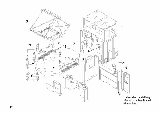
18
9
6
47
7
7
77
7
811
8
5
35
3Details der Darstellung können von dem Modell abweichen.

19
10
1010
10
10
10
Details der Darstellung können von dem Modell abweichen.
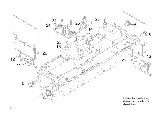
20
24
1325
25
26
6
1211
24 25
26
1 6
6
12
14
Details der Darstellung können von dem Modell abweichen.

21
35
112
10
10
16
17
10
1918
25
10
37
3424
3336
20
32
29
2321
27 28
30
313028
29
10
21
2222
15
16
20
15
1819
15
21
11
24
33
Details der Darstellung können von dem Modell abweichen.

22

23
1 Lokführer E131 723 2 Puffer E130 420 3 Türachsen, Federn E185 766 4 Scheibenwischer E191 014 5 Fenster E191 015 6 Laterne E191 016 7 Isolatoren, Pfeife E191 017 8 Stromabnehmerträger E180 967 9 Scherenstromabnehmer E124 023 10 Schraube E124 197 11 Schraube E124 010 12 Bremsschlauch E180 395 13 Beilagscheibe E124 208 14 Fahrersitz E180 398 15 Bremsbacken E187 972 16 Getriebedeckel und Boden E187 971 17 Motor lg. Welle E129 994 18 Untersetzungszahnr. E133 761 19 Achse E162 587 20 Schienenräumer E140 989 21 Draht, Blech E187 973 22 Schleifsch.,Kohle E184715 23 Schleifer E162 586 24 Schraube E124 014 25 Schraube E124 205 26 Schraube E129 265 27 Haftreifen E131 368 28 Schraube E126 052 29 Unterlegscheibe E126 053 30 SetKuppelstange E180825
Hinweis:EinigeTeilewerdennurohneodermitandererFarbgebung angeboten. Teile, die hier nicht aufgeführt sind, können nur im Rahmen einer Reparatur im Märklin-Reparatur-Service repariert werden.
31 Radsatz E140 997 32 Radsatz E141 006 33 Druckfeder E131 392 34 Befestigungsplatte E140 990 35 Vor/NachläuferradohneKohlen E141001 36 Vor/NachläuferradmitKohlen E141005 37 Kupplung E185792
181041/0612/Sm1EfÄnderungen vorbehalten
© Gebr. Märklin & Cie. GmbH
Gebr. Märklin & Cie. GmbH Stuttgarter Str. 55 - 57 73033 Göppingen Deutschland www.lgb.de
This device complies with Part 15 of the FCC Rules. Operation issubjecttothefollowingtwoconditions:(1) This device may not cause harmful interference, and (2) this device must accept any interference received, inclu-
ding interference that may cause undesired operation.
www.maerklin.com/en/imprint.html