MT-FC48N · manual de uso y mantenimiento manuale d'uso e manutenzione mt-fc48n mechanical...
16
ENGLISH FRANÇAIS DEUTSCH ESPAÑOL ITALIANO 18 M 205 OPERATION AND MAINTENANCE MANUAL NOTICE D'UTILISATION ET ENTRETIEN BEDIENUNGSANLEITUNG MANUAL DE USO Y MANTENIMIENTO MANUALE D'USO E MANUTENZIONE MT-FC48N MECHANICAL FRAME-TYPE HOLE PUNCHING TOOL OUTIL MECANIQUE MANUEL PERCE GOULOTTE WERKZEUG ZUM STANZEN VON KLEINEN KANÄLEN HERRAMIENTA MECÁNICA MANUAL PERFORA CANALETAS UTENSILE MECCANICO MANUALE FORACANALI
Transcript of MT-FC48N · manual de uso y mantenimiento manuale d'uso e manutenzione mt-fc48n mechanical...
1
ENGLISH
FRANÇAIS
DEUTSCH
ESPAÑOL
ITALIANO
18 M 205
OPERATION AND MAINTENANCE MANUALNOTICE D'UTILISATION ET ENTRETIEN
BEDIENUNGSANLEITUNGMANUAL DE USO Y MANTENIMIENTOMANUALE D'USO E MANUTENZIONE
MT-FC48N
MECHANICAL FRAME-TYPE HOLE PUNCHING TOOL OUTIL MECANIQUE MANUEL PERCE GOULOTTE
WERKZEUG ZUM STANZEN VON KLEINEN KANÄLENHERRAMIENTA MECÁNICA MANUAL PERFORA CANALETAS
UTENSILE MECCANICO MANUALE FORACANALI
2
- Year- Année- Jahr- Año- Anno
1 2 3
1 2 3
WARNING LABELS - ETIQUETTES SIGNALETIQUES - WARNSCHILDER - ETIQUETAS DE ATENCION - ETICHETTE D'AVVERTENZA
- Tool type- Outil type- Werkzeug Typ- Herramienta tipo- Tipo di utensile
- Range - Gammes de perçage - Stanzdurchmesser- Rango de perforación - Campo di foratura
MT-FC48N
15,5 ÷ 47,2(mm)
TYPE
Made in Italy
31 2
This manual is the property of Cembre: any reproduction is forbidden without written permission.Ce manuel est la proprieté de Cembre: toute reproduction est interdite sauf autorisation écrite.Diese Bedienungsanleitung ist Eigentum der Firma Cembre.Ohne vorherige schriftliche Genehmigung darf die Bedienungsanleitung weder vollständig noch teilweise vervielfältigt werden.Este manual es propiedad de Cembre. Toda reproducción está prohibida sin autorización escrita.Questo manuale è di proprietà della Cembre: ogni riproduzione é vietata se non autorizzata per scritto.
1
– Before using the tool, carefully read the instructions in this manual.– Avant d’utiliser cet outil, lire attentivement les instructions de cette notice.– Vor Inbetriebnahme unbedingt die Bedienungsanleitung durchlesen.– Antes de utilizar la herramienta, leer atentamente las instrucciones contenidas en este manual.– Prima di utilizzare l’utensile, leggere attentamente le istruzioni contenute in questo manuale.
2
– When operating the tool, keep hands away from the danger zone.– Au cours de l’utilisation, tenir les mains éloignées de la zone de danger.– Während der Arbeit nicht mit den Händen in den Gefahrenbereich fassen.– Durante su utilización, mantenga las manos fuera de la zona de peligro.– Durante l’utilizzo, mantenere le mani fuori dalla zona di pericolo.
3
– Always wear safety glasses and gloves when operating this tool.– Porter toujours les lunettes de protection et les gants de travail.– Immer mit Schutzbrille und Handschuhen bedienen.– Trabajar siempre con las gafas y guantes de seguridad.– Operare sempre con visiera protettiva e guanti da lavoro.
TG03
50

3
ENGLISH
1. GENERAL CHARACTERISTICS
– Application range: suitable for punching holes up to ø 47,2 mm (1.858 in.) in the side wall (*) of cable trunking.– Max. hole centre distance from the edge of the trunking: ............................ 53,5 mm (2.1 in.) – Dimensions: length ........................................................................................................ 251,5 mm (9.9 in.) width (handle with grips) ................................................................... 224 mm (8.82 in.) width ("C" head) ..................................................................................... 66 mm (2.6 in.)– Weight: ................................................................................................................................. 3,28 kg (7.2 lbs)
(*) The tool can also be used to punch holes up to ø 28,5 mm in the base of trunking that is less than 50 mm (2”) deep.
The part code “MT-FC48N” includes the following:– Basic tool– Stud type “B” – Stud type “C” (already mounted)– Stud type “AB” (for previous series punches with 3/8 “-24UNF thread)– Locking screws type “B” (2 pcs).– Locking screws type “C” (2 pcs).– 4 mm Allen key– Plastic carrying case type VAL-P30
2. INSTRUCTIONS FOR USE
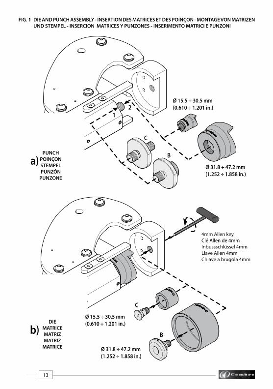
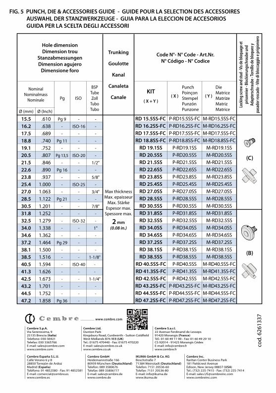
2.1) Setting– Consult the table in Fig. 5 to select the RD... Punching Kit suitable for the hole to be made..– Screw the punch directly onto the appropriate thread of the stud (B or C). Tighten by hand, do not over-tighten (see Fig. 1a). • Punch sizes ø 15.5 - 30.5 mm have a 7/16"-20 UNF thread (stud C). • Punch sizes ø 31.8 - 47.2 mm have a 3/4”-16 UNF thread (stud B).– Insert the appropriate locking screw (B or C) completely into the die and screw the "die-locking screw" assembly into the upper die holder (see Fig 1b). Use the 4mm allen key, supplied with the tool, to tighten the locking screw. NOTE: turn the locking screw, anticlockwise to secure and clockwise to release.
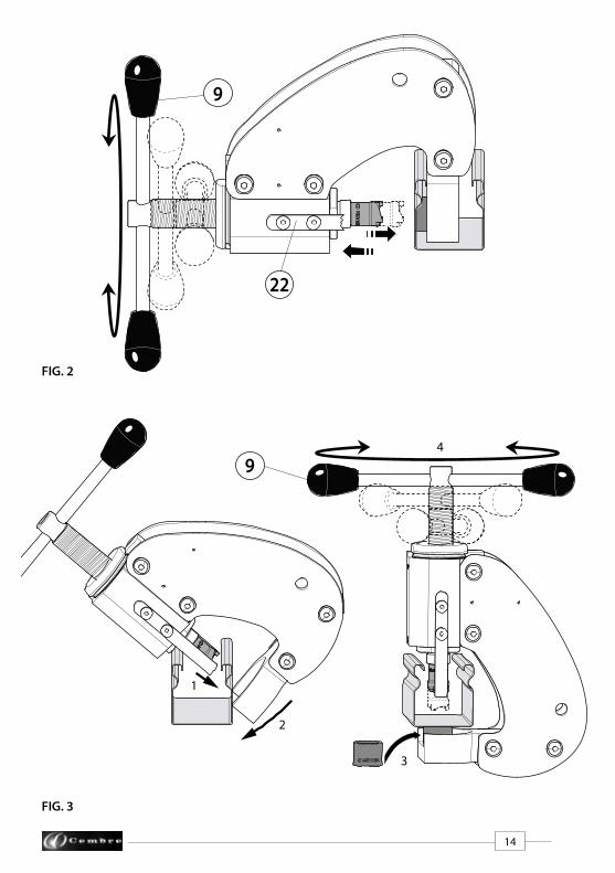
2.2) Punching– Position the tool on the trunking, at the desired hole centre (see Fig. 2). Turn the handle (9) clock- wise until the hole is produced. Turn the handle anti-clockwise to release the punch, the extractors (22) will then permit the tool to be disengaged from the trunking.– Ensure that no punch slugs remain in the die. To remove a slug from the die, insert a small drift through the locking screw (B or C), on to the slug and tap sharply. NOTE: when punching holes in the base of trunking (see Fig. 3) with sides 50 mm (2") high, it is necessary to fit the die after positioning the tool on the trunking. Prior to removing the tool from the trunking, unscrew and remove the die.
4
ENGLISH
5. RETURN TO Cembre FOR OVERHAUL
In the case of a breakdown contact our Area Agent who will advise you on the problem and give you the necessary instructions on how to dispatch the tool to our nearest service Centre; if possible, attach a copy of the Test Certificate supplied by Cembre together with the tool or fill in and attach the form available in the “ASSISTANCE” section of the Cembre website.
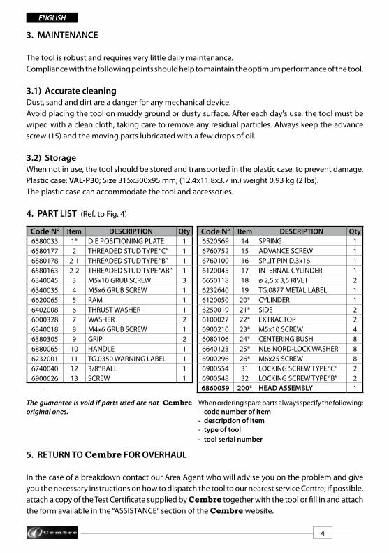
3. MAINTENANCE
The tool is robust and requires very little daily maintenance.Compliance with the following points should help to maintain the optimum performance of the tool.
3.1) Accurate cleaningDust, sand and dirt are a danger for any mechanical device.Avoid placing the tool on muddy ground or dusty surface. After each day's use, the tool must be wiped with a clean cloth, taking care to remove any residual particles. Always keep the advance screw (15) and the moving parts lubricated with a few drops of oil.
3.2) StorageWhen not in use, the tool should be stored and transported in the plastic case, to prevent damage.Plastic case: VAL-P30; Size 315x300x95 mm; (12.4x11.8x3.7 in.) weight 0,93 kg (2 lbs).The plastic case can accommodate the tool and accessories.
4. PART LIST (Ref. to Fig. 4)
The guarantee is void if parts used are not Cembre original ones.
When ordering spare parts always specify the following:- code number of item- description of item- type of tool- tool serial number
Code N° Item DESCRIPTION Qty6580033 1* DIE POSITIONING PLATE 16580177 2 THREADED STUD TYPE “C” 16580178 2-1 THREADED STUD TYPE “B” 16580163 2-2 THREADED STUD TYPE “AB” 16340045 3 M5x10 GRUB SCREW 36340035 4 M5x6 GRUB SCREW 16620065 5 RAM 16402008 6 THRUST WASHER 16000328 7 WASHER 26340018 8 M4x6 GRUB SCREW 16380305 9 GRIP 26880065 10 HANDLE 16232001 11 TG.0350 WARNING LABEL 16740040 12 3/8” BALL 16900626 13 SCREW 1
Code N° Item DESCRIPTION Qty6520569 14 SPRING 16760752 15 ADVANCE SCREW 16760100 16 SPLIT PIN D.3x16 16120045 17 INTERNAL CYLINDER 16650118 18 ø 2,5 x 3,5 RIVET 26232640 19 TG.0877 METAL LABEL 16120050 20* CYLINDER 16250019 21* SIDE 26100027 22* EXTRACTOR 26900210 23* M5x10 SCREW 46080106 24* CENTERING BUSH 86640123 25* NL6 NORD-LOCK WASHER 86900296 26* M6x25 SCREW 86900554 31 LOCKING SCREW TYPE “C” 26900548 32 LOCKING SCREW TYPE “B” 26860059 200* HEAD ASSEMBLY 1
5
FRANÇAIS
1. CARACTERISTIQUES GENERALES
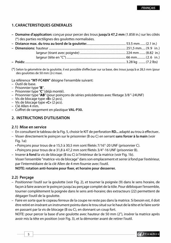
– Domaine d'application: conçue pour percer des trous jusqu'à 47,2 mm (1.858 in.) sur les côtés (*) des parties rectilignes des goulottes normalisées.– Distance max. du trou au bord de la goulotte: ................................................... 53.5 mm ....... (2.1 in.)– Dimensions: hauteur ..................................................................................................... 251,5 mm ..... (9.9 in.) largeur (tirant avec poignée) ............................................................ 224 mm ........ (8.82 in.) largeur (tête en "C") .............................................................................. 66 mm ........... (2.6 in.)– Poids: .................................................................................................................................... 3.28 kg ......... (7.2 lbs)
(*) Selon la géométrie de la goulotte, il est possible d’effectuer sur sa base, des trous jusqu’à ø 28,5 mm (pour des goulottes de 50 mm (2») maxi.
La référence “MT-FC48N” désigne l'ensemble suivant:– Outil de base.– Prisonnier type “B” .– Prisonnier type “C” (déjà monté).– Prisonnier type “AB” (pour poinçons de séries précédentes avec filetage 3/8 “-24UNF)– Vis de blocage type «B» (2 pcs). – Vis de blocage type «C» (2 pcs).– Clé Allen 4 mm.– Coffret de rangement en plastique VAL-P30.
2. INSTRUCTIONS D'UTILISATION
2.1) Mise en service– En consultant le tableau de la Fig. 5, choisir le KIT de perforation RD... adapté au trou à effectuer..– Visser directement le poinçon sur le prisonnier (B ou C) en serrant sans forcer à la main (voir Fig. 1a): • Poinçons pour trous de ø 15,5 à 30,5 mm sont filetés 7/16’’-20 UNF (prisonnier C). • Poinçons pour trous de ø 31,8 à 47,2 mm sont filetés 3/4’’-16 UNF (prisonnier B).– Inserer à fond la vis de blocage (B ou C) à l'intérieur de la matrice (voir Fig. 1b). Visser l'ensemble "matrice-vis de blocage" dans son emplacement et serrer à fond par l’extérieur, par l’intermédiaire de la clé Allen de 4 mm fournie avec l’outil. NOTE: rotation anti-horaire pour fixer, et horaire pour desserrer.
2.2) Perçage– Positionner l’outil sur la goulotte (voir Fig. 2), et tourner la poignée (9) dans le sens horaire, de façon à faire avancer le poinçon jusqu’au perçage complet de la tôle. Pour débloquer l’ensemble, tourner complètement la poignée dans le sens anti-horaire; des extracteurs (22) permettent de dégager l’outil de la goulotte.– Faire en sorte que le copeau ferreux de la coupe ne reste pas dans la matrice. Si besoin est, il doit être retiré en insérant un instrument pointu dans le trou situé sur le haut de la tête et le faire sortir en passant par la vis de blocage (B ou C), en donnant un coup fort. NOTE: pour percer la base d’une goulotte avec hauteur de 50 mm (2"), insérer la matrice après avoir mis la tête en position (voir Fig. 3), et la démonter avant de retirer l’outil.
6
5. ENVOI EN REVISION A Cembre
En cas de dysfonctionnement de l’appareil, merci de vous adresser à notre Agent Régional qui vous conseillera et le cas échéant vous donnera les instructions nécessaires pour envoyer l’appareil à notre Centre de Service le plus proche. Dans ce cas, joindre une copie du Certificat d’Essai livré par Cembre avec l’appareil ou remplir et joindre le formulaire disponible dans la section “ASSISTANCE” du site web Cembre.
FRANÇAIS
3. ENTRETIEN
Cet outil est robuste et ne nécessite aucune préocupation ou entretien particulier.Les recommandations qui suivent sont néanmoins souhaitables pour lui assurer une longévité optimum:
3.1) Nettoyage élémentaireVeiller à protéger l'outil de la poussière, du sable et de la boue qui sont un danger à tout système mecanique. Chaque jour après utilisation, l'outil doit être nettoyé à l'aide d'un chiffon propre,ne jamais oublier de bien huiler la vis d’avancement (15) ainsi que les parties mobiles, mais avec quelques gouttes d’huile.
3.2) RangementIl est de bonne règle de remettre l' outil dans son coffret, fermé, après usage, en protection des chocs et de la poussière. Ce coffret (type VAL-P30), a comme dimensions 315x300x95 mm (12.4x11.8x3.7 in.) et un poids de 0,93 kg (2 lbs), est adapté pour contenir l'outil et les accessoires pour la perforation.
4. PIECES DETACHEES (Voir Fig. 4)
La garantie perd tout effet en cas d'emploi de pièces détachées différentes des pièces d'origine Cembre.
Lors de la commande de pièces détachées, veuillez indiquer toujours les éléments suivants:- numéro de code article de la pièce- désignation de la pièce- type d'outil- numéro de série de l'outil
N° Code Pièce DENOMINATION Q.té6580033 01* PLAQUE 16580177 2 PRISONNIER FILETEE “C” 16580178 2-1 PRISONNIER FILETEE “B” 16580163 2-2 PRISONNIER FILETEE “AB” 16340045 3 VIS SANS TETE M5x10 36340035 4 VIS SANS TETE M5x6 16620065 5 PISTON 16402008 6 COUSSINET 16000328 7 RONDELLE 26340018 8 VIS SANS TETE M4x6 16380305 9 POIGNEE 26880065 10 TIRANT 16232001 11 ETIQUETTE TG 0350 16740040 12 BILLE 3/8" 16900626 13 VIS 1
N° Code Pièce DENOMINATION Q.té6520569 14 RESSORT 16760752 15 VIS D'AVANCEMENT 16760100 16 GOUPILLE D.3x16 16120045 17 CYLINDRE INTERNE 16650118 18 RIVET D.2,5x3,5 26232640 19 PLAQUETTE TG 0877 16120050 20* CYLINDRE 16250019 21* COTE 26100027 22* EXTRACTEUR 26900210 23* VIS M5x10 46080106 24* DOUILLE DE CENTRAGE 86640123 25* RONDELLE NORD-LOCK NL6 86900296 26* VIS M6x25 86900554 31 VIS DE BLOCAGE TYPE "C" 26900548 32 VIS DE BLOCAGE TYPE "B" 26860059 200* TETE MONTEE 1
7
DEUTSCH
1. ALLGEMEINE EIGENSCHAFTEN
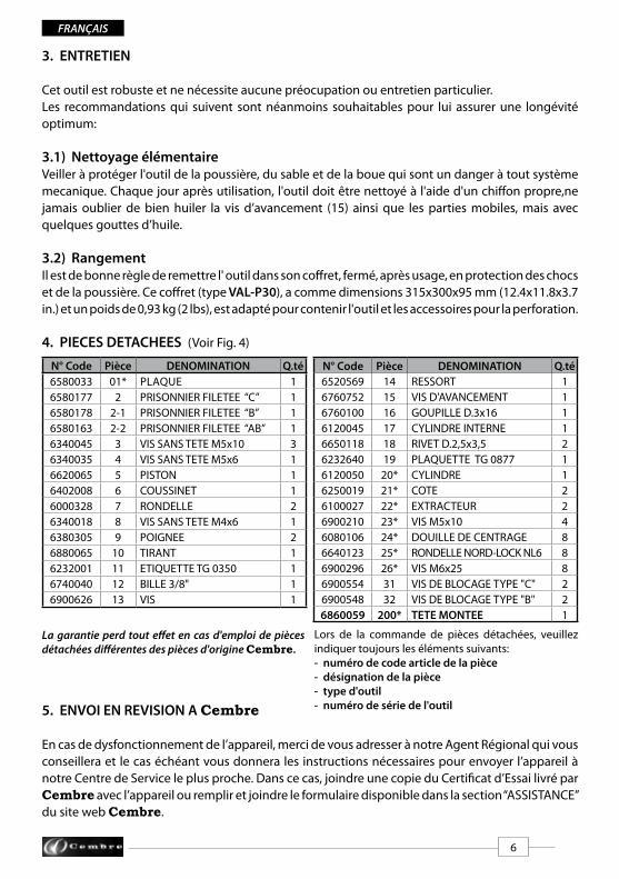
– Anwendungsbereich: Dieses Werkzeug ist zum Stanzen von geraden, genormten Kabelkanälen an den seitlichen Wänden (*) mit einem Durchmesser von max. 47,2 mm (1.858 in.) geeignet. – Der max. Stanzabstand vom Rand des Kanals beträgt: .................................. 53,5 mm (2.1 in.)– Abmasse: Länge ............................................................................................................... 251,5 mm (9.9 in.) Breite (Zungstange mit Griffen) ............................................................. 224 mm (8.83 in.) Breite ("C" Kopf) ........................................................................................... 66 mm (2.6 in.)– Gewicht: .............................................................................................................................. 3,28 kg (7.2 lbs)
(*) Je nach Geometrie können auch Stanzungen bis zum Durchmesser 28,5 mm bei einer Kanalhöhe von 50 mm (2 „) ausgeführt werden.
Unter der Bezeichnung “MT-FC48N” werden folgende Teile geliefert:– Basisausführung.– Adapterschraube Typ “B“– Adapterschraube Typ “C“ (bereits montiert)– Adapterschraube Typ “AB“ (für frühere Serienstempel mit 3/8“-24UNF Gewinde)– Blockierungsschrauben Typ “B“ (2 Stück)– Blockierungsschrauben Typ “C“ (2 Stück)– Inbussschlüssel 4 mm– Kunststoffkoffer VAL-P30
2. BEDIENUNGSHINWEISE
2.1) Vorbereitung– Aus der Tabelle (Bild 5) das für die Stanzung entsprechende KIT RD... auswählen. Für den Bedarf anderer Stanzgrößen als die hier angezeigten, wenden Sie sich bitte an Cembre.– Den Stempel direkt auf der Vorschubschraube (B oder C) befestigen, nicht mit übermäßiger Kraft anziehen (siehe Bild 1a): • Die Stempel mit einem Durchmesser von 15,5 bis 30,5 mm haben ein Gewinde 7/16"-20 UNF (Vorschubschraube C) • Die Stempel mit einem Durchmesser von 31,8 bis 47,2 mm haben ein Gewinde von 3/4"-16 UNF. (Vorschubschraube B)– Die Blockierungsschraube (B oder C) der Matrize tief bis zum Anschlag anziehen (siehe Bild 1b). Von Hand die Blockierungsschraube für die Matrize in die Nut einschrauben und mit dem mit- gelieferten Inbusschlüssel fest anziehen, ACHTUNG: Zur Arretierung nach links drehen und zum Lösen nach rechts drehen.
2.2) Stanzung– Das Werkzeug "sichtbar" an der zu stanzenden Stelle positionieren (siehe Bild 2). Den Griff (9) solange nach rechts drehen bis der Stempel den Kanal vollständig gestanzt hat. Um das Werkzeug wieder zu lösen, die Spindel nach links drehen. Das Werkzeug kann durch den Auszieher (22) aus dem Kanal entfernt werden.– Sich vergewissern, daß keine Stanzrückstände in der Matrize haften bleiben. Sollte dies der Fall sein, können sie durch Einführen eines Werkzeugs in das obere Loch im Kopf bzw. durch der Blockierungsschraube (B oder C) und durch einen heftigen Schlag entfernt werden. HINWEIS: Bei Stanzungen an der Grundfläche des Kanales mit einer Höhe von 50 mm (2") muß das Werkzeug entsprechend Bild 3 "sichtbar" angeordnet werden. Die Matrize darf erst nach Anordnung des Werkzeuges montiert werden und muss vor der Ent- fernung des Werkzeuges vom Kanal demontiert werden.

8
6. EINSENDUNG AN Cembre ZUR ÜBERPRÜFUNG
Sollten an dem Gerät Fehler auftreten, wenden Sie sich bitte an unsere Gebietsvertretung, die Sie gerne beraten und Ihnen alle nötigen Informationen zum Einsenden des Gerätes an unseren Hauptsitz geben wird. Wenn vorhanden, legen Sie dem Gerät bitte eine Kopie des von Cembre mitgelieferten Zertifikates bei oder füllen das, unter dem Bereich “SUPPORT“ der Cembre Website, verfügbare Formular aus und fügen es bei.
Geben Sie bitte bei der Bestellung aller Ersatzteile folgende Informationen an:- Codenummer des Ersatzteils- Beschreibung des Ersatzteils- Art des Gerätes- Artikelnummer des Gerätes
Die Garantie verfällt, wenn nicht Originalteile aus dem Hause Cembre in das Gerät eingebaut werden.
DEUTSCH
3. WARTUNG
Das Werkzeug ist robust und benötigt keine spezielle Pflege oder Instandhaltung.Zur Erhaltung der Garantieansprüche beachten Sie folgende Hinweise:
3.1) PflegeDieses Werkzeug sollte vor starker Verschmutzung geschützt werden. Jeden Tag nach der Arbeit sollte das Werkzeug mit einem Tuch von Schmutz und Staub gereinigt werden. Die Vorschubschraube (15) sowie die beweglichen Teile müssen ständig tropfenweise geölt werden.
3.2) LagerungWenn das Werkzeug nicht benötigt wird, sollte es in der Kunststoffkassette gelagert werden und ist somit gegen Beschädigungen wie Stoss und Staub geschützt. Die Kunststoffkassette (Typ VAL-P30) hat die Abmasse 315x300x95 mm (12.4x11.8x3.7 in.) und ein Gewicht von 0,93 kg (2 lbs). Es kann das Werkzeug und das Zubehör in der Kunststoffkassette gelagert werden.
4. ERSATZTEILLISTE (Siehe Bild 4)
Art.-Nr. Teil BESCHREIBUNG Menge6580033 1* PLATTE 16580177 2 ADAPTERSCHRAUBE "C" 16580178 2-1 ADAPTERSCHRAUBE “B” 36580163 2-2 ADAPTERSCHRAUBE “AB” 16340045 3 INBUSSCHRAUBE M5x10 36340035 4 INBUSSCHRAUBE M5x6 16620065 5 KOLBEN 16402008 6 UNTERLAGE 16000328 7 SCHEIBE 26340018 8 IMBUSSCHRAUBE M4x6 16380305 9 DREHGRIFF 26880065 10 ZUNGSTANGE 16232001 11 AUFKLEBER TG 0350 16740040 12 KUGEL 3/8" 16900626 13 SCHRAUBE 1
Art.-Nr. Teil BESCHREIBUNG Menge6520569 14 FEDER 16760752 15 VORSCHUBSCHRAUBE 16760100 16 FEDERSTIFT D.3x16 16120045 17 ZYLINDER 16650118 18 NIET D.2,5x3,5 26232640 19 TYPENSCHILD TG 0877 16120050 20* ZYLINDER 16250019 21* SEITENTEIL 26100027 22* AUSZIEHER 26900210 23* SCHRAUBE M5x10 46080106 24* ZENTRIERBUCHSE 86640123 25* SCHEIBE NORD-LOCK NL6 86900296 26* SCHRAUBE M6x25 86900554 31 BLOCKIERUNGSCHRAUBE "C" 26900548 32 BLOCKIERUNGSCHRAUBE "B" 26860059 200* VORMONTIERTER KOPF 1
9
ESPAÑOL
1. CARACTERISTICAS GENERALES
– Campo de aplicación: adecuada para la ejecución de orificios hasta ø 47,2 mm (1.858 in.) sobre los lados (*) de elementos rectilíneos de canaletas normalizadas portacables.– Distancia máx. de perforado desde el borde de la canaleta: ...............................53,5 mm (2.1 in.)– Dimensiones: longitud .................................................................................................. 251,5 mm (9.9 in.) anchura (tirante con empuñaduras) ............................................ 224 mm (8.82 in.) anchura (Cabeza a "C") ...................................................................... 66 mm (2.6 in.)– Peso: ...................................................................................................................................... 3,28 kg (7.2 lbs)
(*) En función de su geometría, se pueden realizar perforados hasta ø 28,5 mm también sobre la base de las canaletas que tengan una altura máx de 50 mm (2”).
Con la referencia “MT-FC48N” se identifica el conjunto formado por:– Herramienta base.– Pasador roscado tipo “B” – Pasador roscado tipo “C” (ya montado)– Pasador roscado tipo “AB” (para punzones de series anteriores con rosca 3/8 “-24UNF)– Tornillo de bloqueo tipo “B” (2 pieces)– Tornillo de bloqueo tipo “C” (2 pieces)– Llave Allen 4mm– Caja de almacenamiento tipo VAL-P30
2. INSTRUCCIONES DE USO
2.1) Preparación– Consultando la tabla en la Fig. 5, elegir el kit de perforación RD... adecuado para el orificio que se debe realizar. – Atornillar el punzón directamente sobre el pasador roscado (B o C) apretándolo manualmente sin excederse (Ref. a Fig. 1a): • Los punzones de ø 15.5 a 30.5 mm son de rosca 7/16"- 20 UNF (pasador roscado C). • Los punzones de ø 31.8 a 47.2 mm son de rosca 3/4"-16 UNF (pasador roscado B). – Insertar el tornillo de bloqueo (B o C) hasta bloquearlo en la matriz (Ref. a Fig.1b). Enroscar el conjunto matriz-tornillo de bloqueo en su hueco respectivo en la cabeza, y apretar con la llave Allen de 4 mm suministrada con la herramienta. NOTA: rotación contra horaria para la fijación y rotación horaria para el desmontaje.
2.2) Perforación– Colocar “a la vista” la herramienta en la zona de la canaleta en la que se debe hacer el perforado (ref. a Fig. 2), girar en sentido horario las empuñaduras (9) haciendo avanzar el punzón hasta el corte completo de la chapa. Para desbloquear la herramienta, girar completamente en sentido contra horario las empuñaduras; los extractores (22) permitirán la desvinculación de la canaleta. – Asegurarse de que el desecho del corte no haya sido retenido por la matriz, en ese caso expulsarlo introduciendo un aparato en el orificio superior del cabezal y pasando a través del tornillo de bloqueo (B o C) dar con decisión un golpe firme. NOTA: en el caso de perforado de la base de las canaletas con altura de 50 mm (2") colocar la herramienta “a la vista” como está ilustrado en la Fig. 3; será necesario montar la matriz solamente después de haber colocado la herramienta y desmontarla antes de desvincular la herramienta de la canaleta.
10
5. DEVOLUCION A Cembre PARA REVISIONES
En caso de fallo de la herramienta, contactar con nuestro Agente de Zona quien les aconsejará y eventualmente les facilitará las instrucciones necesarias para remitir la herramienta a nuestro centro de servicio más cercano. En tal caso, adjuntar a ser posible una copia del Certificado de Ensayo en-tregado en su día por Cembre con la herramienta o completar y adjuntar el formulario disponible en la sección “ASISTENCIA” del sitio web Cembre.
ESPAÑOL
3. MANTENIMIENTO
Esta herramienta es robusta y no requiere cuidados especiales para obtener un funcionamiento correcto, bastará con seguir algunas sencillas precauciones:
3.1) Limpieza adecuadaTenga presente que el polvo, la arena y la suciedad en general, rapresentan un peligro para toda herramienta mecánica. Tras cada día de uso, se debe limpiar la herramienta con un trapo limpio, teniendo cuidado de eliminar la suciedad depositada, mantener siempre engrasados, con pocas gotas, los tornillos de avance (15) y las partes móviles.
3.2) Almacenamiento Para proteger la herramienta de golpes accidentales y del polvo cuando no se va a utilizar, es con-veniente guardarla en su estuche de cierre hermético.Dicho estuche (mod. VAL-P30) de dimensiones 315x300x95 mm (12.4x11.8x3.7 in.) y peso 0,93 kg (2 lbs) es apropiado para almacenar la herramienta y los accesorios de perforación.
4. LISTA DE COMPONENTES (Ref. a Fig. 4)
La garantia pierde eficacia si se utilizan piezas de re-puesto distintas de las originales Cembre.
N°Código Elemento DESCRIPCION C.dad6580033 1* PLAQUETA 16580169 2 PASADOR ROSCADO "C" 16580178 2-1 PASADOR ROSCADO "B" 16580163 2-2 PASADOR ROSCADO "AB" 16340045 3 TORNILLO M5x10 36340035 4 TORNILLO M5x6 16620065 5 PISTON 16402008 6 COJINETE 16000328 7 ARANDELA 26340018 8 TORNILLO M4x6 16380305 9 EMPUÑADURA 26880065 10 TIRANTE 16232001 11 ETIQUETA TG 0350 16740040 12 BOLA 3/8" 16900626 13 TORNILLO 16760752 15 TORNILLO DE AVANCE 1
N°Código Elemento DESCRIPCION C.dad6520569 14 MUELLE 16760752 15 TORNILLO DE AVANCE 16760100 16 PASADOR D.3x16 16120045 17 CILINDRO INTERIOR 16650118 18 REMACHE D.2,5x3,5 26232640 19 TARJETA TG 0877 16120050 20* CILINDRO 16250019 21* FLANCO 26100027 22* EXTRACTOR 26900210 23* TORNILLO M5x10 46080106 24* ANILLO DE CENTRADO 86640123 25* ARANDELA NORD-LOCK NL6 86900296 26* TORNILLO M6x25 86900554 31 TORNILLO DE BLOQUEO "C" 26900548 32 TORNILLO DE BLOQUEO "B" 26860059 200* CABEZA MONTADA 1
Al pedir piezas de repuesto, indicar siempre los ele-mentos siguientes:- número de código del elemento- descripción del elemento- tipo de herramienta- número de serie de la herramienta
11
ITALIANO
1. CARATTERISTICHE GENERALI
– Campo di applicazione: adatto all'esecuzione di fori fino a ø 47,2 mm (1.858 in.) sui lati (*) di elementi rettilinei di canali normalizzati portacavi.– Distanza massima di foratura dal bordo del canale: ........................................ 53,5 mm (2.1 in.)– Dimensioni: lunghezza .................................................................................................. 251,5 mm (9.9 in.) larghezza (tirante con impugnature) .............................................. 224 mm (8.82 in.) larghezza (testa a "C") ........................................................................... 66 mm (2.6 in.)– Peso: ...................................................................................................................................... 3,28 kg (7.2 lbs)
(*) In funzione della loro geometria, è possibile eseguire forature fino a ø 28,5 mm anche sulla base di canali di altezza max. 50 mm (2”).
Con la sigla “MT-FC48N” si identifica l'assieme formato da:– Utensile base– Prigioniero tipo “B” – Prigioniero tipo “C” (già montato)– Prigioniero tipo “AB” (per punzoni serie precedenti con filettatura 3/8”-24UNF)– Vite di bloccaggio tipo “B” (2 pz)– Vite di bloccaggio tipo “C” (2 pz)– Chiave a brugola da 4 mm– Valigetta di contenimento tipo VAL-P30
2. ISTRUZIONI PER L’USO
2.1) Preparazione– Consultando la Tabella in Fig. 5, scegliere il Kit di foratura RD... adatto al foro da eseguire, per esigenze di foratura diverse da quelle riportate contattare la Cembre.– Avvitare il punzone direttamente sul prigioniero (B o C) serrandolo manualmente senza eccedere (Rif. a Fig. 1a). • I punzoni da ø 15.5 a 30.5 mm hanno una filettatura da 7/16"-20 UNF (prigioniero C). • I punzoni da ø 31.8 a 47.2 mm hanno una filettatura da 3/4"-16 UNF (prigioniero (B). – Inserire a fondo fino alla battuta la vite di bloccaggio (B o C) all'interno della matrice (Rif. a Fig. 1b). Avvitare manualmente l'insieme "matrice-vite di bloccaggio" nella relativa sede della testa, serrare a fondo agendo dall'esterno con la chiave a brugola da 4 mm fornita a corredo dell'utensile. NOTA: rotazione antioraria per il serraggio e rotazione oraria per lo smontaggio. 2.2) Foratura– Posizionare "a vista" l'utensile sulla canalina nel punto di foratura (Rif. a Fig. 2).– Ruotare in senso orario le impugnature (9) facendo avanzare il punzone sino alla completa tran- ciatura della lamiera. Per sbloccare l'utensile, ruotare completamente in senso antiorario le impugnature; gli estrattori (22) permetteranno il disimpegno dell'utensile dalla canalina. – Accertarsi che lo sfrido di tranciatura non sia stato trattenuto nella matrice, in tal caso espellerlo inserendo un attrezzo nel foro superiore della testa e passando attraverso la vite di bloccaggio (B o C), assestare un colpo ben deciso. NOTA: nel caso di foratura della base di canali con altezza 50 mm (2") posizionare l'utensile "a vista" come illustrato in Fig. 3; sarà necessario montare la matrice solo dopo aver posizionato l'utensile e smontarla prima di disimpegnare l'utensile dal canale.
12
5. RESA ALLA Cembre PER REVISIONE
In caso di guasto contattare il nostro Agente di Zona il quale vi consiglierà in merito e fornirà le istruzioni necessarie per l’invio dell’utensile alla nostra Sede; se possibile, allegare copia del Certi-ficato di Collaudo a suo tempo fornito dalla Cembre con l’utensile oppure, compilare ed allegare il modulo disponibile nella sezione “ASSISTENZA” del sito web Cembre.
3. MANUTENZIONE
L'utensile é robusto e non richiede attenzioni particolari; per garantirne un corretto funzionamento basterà osservare alcune semplici precauzioni:
3.1) Accurata puliziaTenere presente che la polvere, la sabbia e lo sporco possono causare inconvenienti ad ogni tipo di apparecchiatura meccanica per cui é conveniente ripulire frequentemente l'utensile con uno straccio pulito e tenere sempre oliati, con poche gocce, lo spintore (15) e le parti mobili.
3.2) CustodiaQuando l'utensile non viene usato, é bene custodirlo nell'apposita valigetta in materiale plastico al riparo dalla polvere e da urti accidentali. Questa valigetta (tipo VAL-P30) adatta al contenimento dell'utensile e degli accessori per la foratura, ha dimensioni 315x300x95 mm (12.4x11.8x3.7 in.) e pesa 0,93 kg (2 lbs).
4. LISTA DEI COMPONENTI (Rif. a Fig. 4)
ITALIANO
La garanzia decade qualora vengano utilizzate parti di ricambio non originali Cembre.
Per ordinare parti di ricambio, specificare sempre i seguenti punti:- numero di codice del componente- denominazione del componente- tipo dell'utensile- numero di matricola dell'utensile
N°Codice Part. DENOMINAZIONE Q.tà6580033 1* PIASTRINA DI FERMO 16580177 2 PRIGIONIERO TIPO "C" 16580178 2-1 PRIGIONIERO TIPO “B” 16580163 2-2 PRIGIONIERO TIPO “AB” 16340045 3 GRANO M5x10 36340035 4 GRANO M5x6 16620065 5 PISTONE 16402008 6 GABBIA ASSIALE 16000328 7 RALLA 26340018 8 GRANO M4x6 16380305 9 IMPUGNATURA 26880065 10 TIRANTE 16232001 11 ETICHETTA TG 0350 16740040 12 SFERA 3/8" 16900626 13 VITE A COLLETTO 1
N°Codice Part. DENOMINAZIONE Q.tà6520569 14 MOLLA SPINGI SFERA 16760752 15 SPINTORE 16760100 16 SPINA ELASTICA D.3x16 16120045 17 CILINDRO INTERNO 16650118 18 RIVETTO D.2,5x3,5 26232640 19 TARGHETTA TG 0877 16120050 20* CILINDRO 16250019 21* FIANCATA 26100027 22* ESTRATTORE 26900210 23* VITE M5x10 TSEI 46080106 24* BUSSOLA CENTRAGGIO 86640123 25* ROND. NORD-LOCK NL6 86900296 26* VITE M6x25 TBEI 86900554 31 VITE DI BLOCC. TIPO "C" 26900548 32 VITE DI BLOCC. TIPO "B" 26860059 200* TESTA MONTATA 1
13
FIG. 1 DIE AND PUNCH ASSEMBLY - INSERTION DES MATRICES ET DES POINÇON - MONTAGE VON MATRIZEN UND STEMPEL - INSERCION MATRICES Y PUNZONES - INSERIMENTO MATRICI E PUNZONI
a)
b)
PUNCHPOINÇONSTEMPELPUNZÓN
PUNZONE
DIEMATRICEMATRIZMATRIZ
MATRICE
Ø 15.5 ÷ 30.5 mm (0.610 ÷ 1.201 in.)
Ø 31.8 ÷ 47.2 mm (1.252 ÷ 1.858 in.)
Ø 15.5 ÷ 30.5 mm (0.610 ÷ 1.201 in.)
Ø 31.8 ÷ 47.2 mm (1.252 ÷ 1.858 in.)
4mm Allen keyClé Allen de 4mmInbussschlüssel 4mmLlave Allen 4mmChiave a brugola 4mm
C
B
C
B
12
a)
14
9
9
FIG. 2
FIG. 3
1
2
3
4
22

15
FIG
. 4
1
2
5
8
11
18
20
21
22
23
24
19
43
7
7
15 13
6
109
16
14 17
12
• p/n
200
••
•
•
•
•
2526
••
C
31
32
2-1
2-2
B AB
16
FIG. 5 PUNCH, DIE & ACCESSORIES GUIDE - GUIDE POUR LA SELECTION DES ACCESSOIRES AUSWAHL DER STANZWERKZEUGE - GUIA PARA LA ELECCION DE ACCESORIOS GUIDA PER LA SCELTA DEGLI ACCESSORI
Cembre Ltd.Dunton ParkKingsbury Road, Curdworth - Sutton ColdfieldWest Midlands B76 9EB (UK)Tel.: 01675 470440 - Fax: 01675 470220E-mail: [email protected]
Cembre S.p.A. Via Serenissima, 925135 Brescia (Italia)Telefono: 030 36921Telefax: 030 3365766E-mail: [email protected]
Cembre S.a.r.l.22 Avenue Ferdinand de Lesseps91420 Morangis (France) Tél.: 01 60 49 11 90 - Fax: 01 60 49 29 10CS 92014 - 91423 Morangis CédexE-mail: [email protected]
Cembre España S.L.U.Calle Verano 6 y 828850 Torrejón de ArdozMadrid (España)Teléfono: 91 4852580 - Fax: 91 4852581E-mail: [email protected]
Cembre GmbH Heidemannstraße 16680939 München (Deutschland)Telefon: 089 3580676Telefax: 089 35806777E-mail: [email protected]
Cembre Inc. Raritan Center Business Park181 Fieldcrest AvenueEdison, New Jersey 08837 (USA)Tel.: (732) 225-7415 - Fax: (732) 225-7414E-mail: [email protected]
www.cembre.com
IKUMA GmbH & Co. KG Boschstraße 771384 Weinstadt (Deutschland)Telefon: 7151 20536-60Telefax: 7151 20536-80E-mail: [email protected]
cod.
626
1337
15.5 .610 16.2 .638 17.5 .689 18.8 .740 19.1 .752 20.5 .807 21.5 .846 22.6 .890 23.8 .937 25.4 1.000 27.0 1.063 28.5 1.122 30.5 1.201 31.8 1.252 32.5 1.279 34.0 1.338 34.6 1.362 37.2 1.464 38.1 1.500 38.5 1.516 40.5 1.594 41.3 1.626 42.5 1.673 43.2 1.701 44.5 1.752 47.2 1.858
Pg 9 - -
- ISO-16 -
- - -
Pg 11 - -
- - -
Pg 13,5 ISO-20 -
- - 1/2"
Pg 16 - -
- - 5/8"
- ISO-25 -
- - 3/4"
Pg 21 - -
- - 7/8"
- - -
- ISO-32 -
- - 1"
- - -
Pg 29 - -
- - -
- - 1-1/8"
- ISO-40 -
- - -
- - 1-1/4"
- - -
- - -
Pg 36 - -
Ø (mm) Ø (Inch)
Pg ISO
BSPTubeZoll
TuboTubo
KIT
( X + Y )
PunchPoinçonStempelPunzónPunzone
Hole dimensionDimension trou
StanzabmessungenDimension agujero
Dimensione foro
Nominal Nominalmass
Nominale( X ) ( Y )
DieMatriceMatrizeMatrizMatrice
(C)
(B)
Max thicknessMax. epaisseur
Max. StärkeEspesor max.
Spessore max.
2 mm(0.08 in.)
RD 15.5SS-FC RD 16.2SS-FC RD 17.5SS-FC RD 18.8SS-FC
RD 19.1SSRD 20.5SSRD 21.5SSRD 22.6SSRD 23.8SSRD 25.4SSRD 27.0SSRD 28.5SSRD 30.5SSRD 31.8SSRD 32.5SSRD 34.0SSRD 34.6SSRD 37.2SSRD 38.1SSRD 38.5SS
RD 40.5SS-FCRD 41.3SS-FCRD 42.5SS-FC
RD 43.2SS-FC RD 44.5SS-FC RD 47.2SS-FC
Lock
ing
scre
w an
d st
ud - V
is de
blo
quag
e et
priso
nnie
r - B
lock
ieru
ngsc
hrau
be u
nd
Adap
ters
chra
ube -
Torn
illo
de b
loqu
eo y
pasa
dor r
osca
do - V
ite d
i blo
ccag
gio
e prig
ioni
ero
P-RD15.5SS-FC P-RD16.2SS-FCP-RD17.5SS-FCP-RD18.8SS-FC
P-RD19.1SSP-RD20.5SSP-RD21.5SSP-RD22.6SSP-RD23.8SSP-RD25.4SSP-RD27.0SSP-RD28.5SSP-RD30.5SSP-RD31.8SSP-RD32.5SSP-RD34.0SSP-RD34.6SSP-RD37.2SSP-RD38.1SSP-RD38.5SSP-RD40.5SSP-RD41.3SSP-RD42.5SS
P-RD43.2SS-FCP-RD44.5SS-FCP-RD47.2SS-FC
M-RD15.5SS-FC M-RD16.2SS-FCM-RD17.5SS-FCM-RD18.8SS-FC
M-RD19.1SSM-RD20.5SSM-RD21.5SSM-RD22.6SSM-RD23.8SSM-RD25.4SSM-RD27.0SSM-RD28.5SSM-RD30.5SSM-RD31.8SSM-RD32.5SSM-RD34.0SSM-RD34.6SSM-RD37.2SSM-RD38.1SSM-RD38.5SS
M-RD40.5SS-FCM-RD41.3SS-FCM-RD42.5SS-FCM-RD43.2SS-FCM-RD44.5SS-FCM-RD47.2SS-FC
Code N°- N° Code - Art.Nr.N° Código - N° Codice
Trunking
Goulotte
Kanal
Canaleta
Canale

![Die Bergpredigt Mt 5-7 Thomas Jettel 2012. I. In welchem Zusammenhang steht die Rede? Die 5 Reden bei Mt Mt 5-7 Die Verfassung [Charakter] des Königreiches.](https://static.fdokument.com/doc/165x107/55204d6249795902118b7826/die-bergpredigt-mt-5-7-thomas-jettel-2012-i-in-welchem-zusammenhang-steht-die-rede-die-5-reden-bei-mt-mt-5-7-die-verfassung-charakter-des-koenigreiches.jpg)