PolyCompact Kopfstelle PolyCompact Headend V2.0-A4.pdf · 4 1 Sicherheitsvorkehrungen Vor dem...
16
PolyCompact Kopfstelle PolyCompact Headend Bedienungsanleitung/ Operating manual 0901093 V2.0
Transcript of PolyCompact Kopfstelle PolyCompact Headend V2.0-A4.pdf · 4 1 Sicherheitsvorkehrungen Vor dem...

PolyCompact Kopfstelle PolyCompact Headend
Bedienungsanleitung/ Operating manual
0901093 V2.0
2
HINWEIS Der Inhalt dieses Firmenhandbuches ist urheberrecht-lich geschützt und darf ohne Genehmigung des Ver-fassers weder ganz noch teilweise in irgendeiner Form vervielfältigt oder kopiert werden. Änderungen in diesem Firmenhandbuch, die ohne Zustimmung des Verfassers erfolgen, können zum Verlust der Gewähr-leistung bzw. zur Ablehnung der Produkthaftung sei-tens des Herstellers führen. Für Verbesserungsvor-schläge ist der Verfasser dankbar.
Verfasser: Polytron-Vertrieb GmbH
Postfach 10 02 33 75313 Bad Wildbad
Germany
Unten stehende Hervorhebungen werden in diesem Handbuch mit folgenden Bedeutungen verwendet:
HINWEIS gilt für technische Erfordernisse, die der Benutzer der Geräte besonders beachten muss, um eine einwandfreie Funktion der Geräte/Anlage zu gewährleisten.
ACHTUNG bezieht sich auf Anweisungen, die genau einzuhalten sind, um eine Beschädigung oder Zerstörung des Gerätes zu vermei-den.
VORSICHT steht für Anweisungen, deren Nichtbe-achtung eine Gefährdung von Personen nicht ausschließt.
Bei Hinweisen auf ein durch eine Ortszahl versehenes Bauteil z.B. (Bild 1/3) bezieht sich in diesem Beispiel der Hinweis auf Bild 1 Ortszahl 3.
NOTE
The contents of this company manual are copyrighted and must not be duplicated or copied in any form, ei-ther partially or in full, without the prior consent of the editor. Changes in this company manual which are carried out without consent of the creator can lead to the loss of the guarantee or to the rejection of the product liability of the manufacturer. The editor is grateful for improvement.
Editor: Polytron-Vertrieb GmbH
Postfach 10 02 33 75313 Bad Wildbad
Germany
The following emphases are used in this manual with the following meanings:
NOTE applies to technical requirements which must be taken into account to ensure a faultless function of the device/plant.
ATTENTION refers to instructions which have to be adhered exactly to avoid damage or destruction of the device.
CAUTION applies to instructions whose nonob-servance doesn't exclude the endan-gering of persons.
At references to a component provided by a place number (e.g. figure 1/3) the reference corresponds to picture 1 place number 3.
3
Inhaltsverzeichnis / Table of contents
1 Sicherheitsvorkehrungen / Safety precautions................................................................................................4 1.1 Hinweise zu Sicherheitsanforderungen an Antennenanlagen /
References to safety requirements at antenna systems........................................................................................5
2 Beschreibung / Description................................................................................................................................6
3 Vorbereitungen / Preparations...........................................................................................................................7 3.1 Kopfstelle erden / Headend grounding..................................................................................................................7
3.2 Koaxialkabel erden / Grounding coaxial cables ....................................................................................................7
3.3 F-Stecker aufschrauben / Fitting F-Connectors ....................................................................................................7
4 Programmierung / Programming .......................................................................................................................7 4.1 Programmieren von DVB-S-Eingangsfrequenzen / Programming DVB-S Input Frequencies..............................8
4.2 Programmieren von DVB-T-Eingangsfrequenzen / Programming DVB-T Input Frequencies ..............................8
4.3 Programmiersperre / Programming Lock ..............................................................................................................8
4.4 Wiederherstellen der Grundeinstellung (Werkseinstellung) / Activating the default setting (factory setting)........8
4.5 Kopieren der Daten über CopyKey / Copying data using the CopyKey................................................................9
4.6 Software update durch Wechseln des EPROMs / Software update by changing the EPROM ............................9
5. Maße und Anschlusszeichnungen SPM 1000 plus / Dimensions and Connection drawings SPM 1000 plus .................................................................................11
6 Montage / Assembly..........................................................................................................................................12 6.1 19"-Montage / Installation in a 19" rack...............................................................................................................12
6.2 Wandmontage / Wall mounting ...........................................................................................................................12
7 Anlagenbeispiele / Installation example .........................................................................................................13 7.1 Aufbereitung von 20 Programmen von 2 Satelliten / Processing 20 channels from 2 satellites.........................13
7.2 Kombination mit zwei Überwachungskameras / Combination with two monitoring cameras .............................13
7.3 Verteilung der Eingangssignale / Input signal distribution...................................................................................14
8 Technische Daten / Technical Data .................................................................................................................15

4
1 Sicherheitsvorkehrungen Vor dem Arbeiten am Grundgerät SPM 1000plus bitte unbedingt folgende Sicherheitsbestimmun-gen sorgfältig lesen!
ACHTUNG Das Öffnen des Gerätes sollte nur von autorisiertem Fachpersonal durchgeführt werden. Zum Aus- und/oder Einbau eines Moduls muss das Grundgerät immer stromlos sein!
Netzanschluss und Netzkabel Das Gerät darf nur an einem Stromnetz mit einer Wechselspannung von 190 – 250 VAC (50/60 Hz) betrieben werden.
Anschlusskabel Anschlusskabel immer stolperfrei verlegen!
Erdung der Anlage Nach den EN 50 083 / VDE 0855 Bestimmungen muss die Satellitenanlage den Sicherheitsbestim-mungen wie z.B. Erdung, Potenzialausgleich, etc. entsprechen.
Feuchtigkeit und Aufstellungsort Das Gerät darf nicht Tropf- oder Spritzwasser ausge-setzt werden. Bei Kondenswasserbildung unbedingt warten, bis das Gerät wieder trocken ist.
Umgebungstemperatur und Hitzeeinwirkung Die Umgebungstemperatur darf +50 °C nicht über-schreiten. Die Lüftungsschlitze des Gerätes dürfen auf keinen Fall abgedeckt werden. Zu starke Hitze-einwirkung oder Wärmestau beeinträchtigen die Le-bensdauer des Gerätes und können eine Gefahren-quelle sein. Das Gerät darf nicht direkt über oder in der Nähe von Wärmequellen (z.B. Heizkörpern, Heizungsanlagen o.ä.) montiert werden, wo das Gerät Hitzestrahlung oder Öldämpfen ausgesetzt ist. Wegen der Brandgefahr durch Überhitzung oder Blitzeinschlag ist es empfehlenswert, das Gerät auf einer feuerfesten Unterlage zu montieren.
Sicherungen Sicherungen sollten nur von autorisiertem Fachper-sonal gewechselt werden. Es dürfen nur Sicherungen des gleichen Typs eingesetzt werden.
1 Safety precautions Before working on the base unit SPM 1000plus please read the following safety precautions care-fully!
ATTENTION The unit should only be opened by qualified persons. For removement and/or installation of a module the base unit must always be currentless!
Mains connection and mains cable Only operate the device at a specified voltage of 190 – 250 VAC (50/60 Hz).
Connection cable Lay cables that they cannot be tripped over!
Grounding of the system According to the regulations EN 50 083 / VDE 0855 the satellite plant must correspond to the safety regu-lations e.g. grounding, potential equalization, etc.
Humidity and place of assembly The equipment may not be exposed dripping or splash-water. In case of condensed water formation wait until the device is dry again.
Ambient temperature and influence of heat The ambient temperature must not exceed +50 °C. Don’t cover the louvers of the device. To strong heat effect or accumulation of heat impairs the life span of the equipment and can be a source of danger. The unit must not be installed directly above or in the immediate vicinity of heat sources (e.g. heating ele-ments, heating systems or similarly.), where the equipment is exposed to heat radiation or oil vapour. Due to the risk of fire by overheating or lightning strike it is recommendable to install the equipment on a non-combustible base.
Fuses Fuses should be changed only from authorized tech-nical personnel. Only fuses of the same type may be used.
5
ACHTUNG Diese Baugruppe enthält ESD-Bauteile! (ESD = Elektrostatisch emp-findliches Bauteil)
Eine elektrostatische Entladung ist ein elektrischer Stromimpuls, der - ausgelöst durch große Span-nungsdifferenz - auch über ein normalerweise e-lektrisch isolierendes Material fließen kann.
Um die Zuverlässigkeit von ESD-Baugruppen ge-währleisten zu können, ist es notwendig, beim Um-gang die wichtigsten Handhabungsregeln zu beach-ten:
Elektrostatisch empfindliche Baugruppen dürfen nur an elektrostatisch geschützten Arbeitsplätzen (EPA) verarbeitet werden!
Auf ständigen Potentialausgleich achten!
Personenerdung über Handgelenk- und Schuh-erdung sicherstellen!
Elektrostatisch aufladbare Materialien wie norma-les PE, PVC, Styropor, etc. vermeiden!
Elektrostatische Felder >100 V/cm vermeiden!
Nur gekennzeichnete und definierte Verpa-ckungs- und Transportmaterialien einsetzen!
Schäden durch fehlerhaften Anschluss und/oder unsachgemäße Handhabung sind von jeglicher Haftung ausgeschlossen.
1.1 Hinweise zu Sicherheitsanforderungen an Antennenanlagen
Ihre Antennenanlage muss den Sicherheitsanforde-rungen nach EN 50 083 / VD 0855 Teil 1 entspre-chen
Denken Sie daran: Wegen Brandgefahr durch Blitzeinschlag ist es emp-fehlenswert, alle metallischen Teile auf einer nicht brennbaren Unterlage zu montieren. Brennbar sind Holzbalken, Holzbretter, Kunststoffe etc.
ATTENTION This unit is equipped with ESD- components! (ESD = Electrostatic Sensitive Device)
An electrostatic discharge is an electrical current pulse, which can flow triggered by large tension difference also over a normally electrically isolating material.
In order to be able to ensure the reliability of ESD as-semblies, it is necessary to adhere the most impor-tant handling rules:
Electrostatically sensitive assemblies may be processed only on electrostatically protected work place (EPA)!
Pay attention to permanent potential compensa-tion!
Guarantee person grounding by wrist and shoe grounding!
Avoid electrostatically rechargeable materials like normal PE, PVC, polystyrene, etc.!
Avoid electrostatic fields >100 V/cm!
Use only labeled and defined packing and trans-portation materials!
Damages by faulty connection and/or inexpert handling are excluded from any liability.
1.1 References to safety requirements at antenna systems.
Your antenna system must comply with EN 50 083 / VD 0855 part 1.
Remember: Due to the risk of fires caused by lightning strikes, all metal parts must be mounted on a non-combustible base. Combustible materials include wooden beams and boards, plastic boards etc.
6
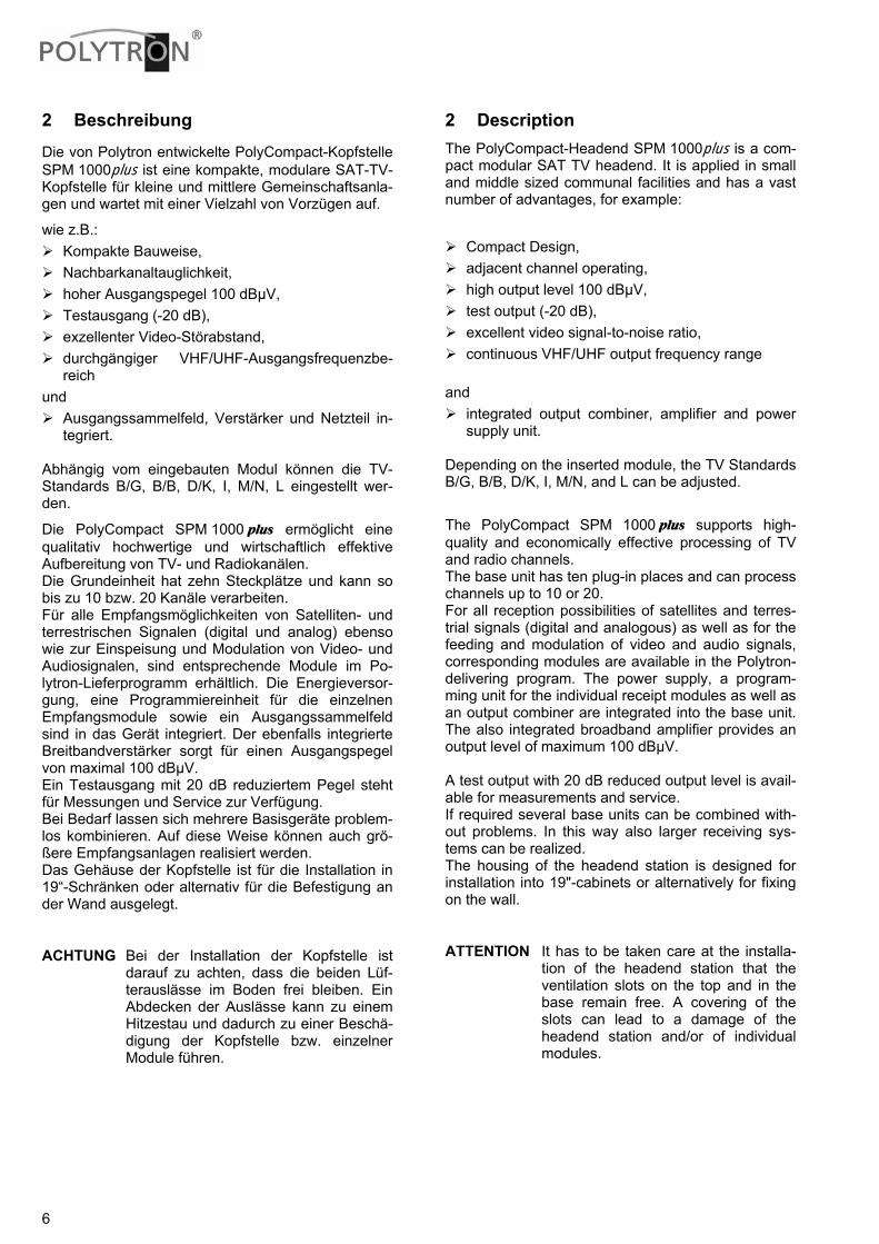
2 Beschreibung
Die von Polytron entwickelte PolyCompact-Kopfstelle SPM 1000plus ist eine kompakte, modulare SAT-TV-Kopfstelle für kleine und mittlere Gemeinschaftsanla-gen und wartet mit einer Vielzahl von Vorzügen auf.
wie z.B.: Kompakte Bauweise, Nachbarkanaltauglichkeit, hoher Ausgangspegel 100 dBµV, Testausgang (-20 dB), exzellenter Video-Störabstand, durchgängiger VHF/UHF-Ausgangsfrequenzbe-
reich und
Ausgangssammelfeld, Verstärker und Netzteil in-tegriert.
Abhängig vom eingebauten Modul können die TV-Standards B/G, B/B, D/K, I, M/N, L eingestellt wer-den.
Die PolyCompact SPM 1000 plus ermöglicht eine qualitativ hochwertige und wirtschaftlich effektive Aufbereitung von TV- und Radiokanälen. Die Grundeinheit hat zehn Steckplätze und kann so bis zu 10 bzw. 20 Kanäle verarbeiten. Für alle Empfangsmöglichkeiten von Satelliten- und terrestrischen Signalen (digital und analog) ebenso wie zur Einspeisung und Modulation von Video- und Audiosignalen, sind entsprechende Module im Po-lytron-Lieferprogramm erhältlich. Die Energieversor-gung, eine Programmiereinheit für die einzelnen Empfangsmodule sowie ein Ausgangssammelfeld sind in das Gerät integriert. Der ebenfalls integrierte Breitbandverstärker sorgt für einen Ausgangspegel von maximal 100 dBµV. Ein Testausgang mit 20 dB reduziertem Pegel steht für Messungen und Service zur Verfügung. Bei Bedarf lassen sich mehrere Basisgeräte problem-los kombinieren. Auf diese Weise können auch grö-ßere Empfangsanlagen realisiert werden. Das Gehäuse der Kopfstelle ist für die Installation in 19“-Schränken oder alternativ für die Befestigung an der Wand ausgelegt.
ACHTUNG Bei der Installation der Kopfstelle ist darauf zu achten, dass die beiden Lüf-terauslässe im Boden frei bleiben. Ein Abdecken der Auslässe kann zu einem Hitzestau und dadurch zu einer Beschä-digung der Kopfstelle bzw. einzelner Module führen.
2 Description The PolyCompact-Headend SPM 1000plus is a com-pact modular SAT TV headend. It is applied in small and middle sized communal facilities and has a vast number of advantages, for example:
Compact Design, adjacent channel operating, high output level 100 dBµV, test output (-20 dB), excellent video signal-to-noise ratio, continuous VHF/UHF output frequency range
and
integrated output combiner, amplifier and power supply unit.
Depending on the inserted module, the TV Standards B/G, B/B, D/K, I, M/N, and L can be adjusted.
The PolyCompact SPM 1000 plus supports high-quality and economically effective processing of TV and radio channels. The base unit has ten plug-in places and can process channels up to 10 or 20. For all reception possibilities of satellites and terres-trial signals (digital and analogous) as well as for the feeding and modulation of video and audio signals, corresponding modules are available in the Polytron-delivering program. The power supply, a program-ming unit for the individual receipt modules as well as an output combiner are integrated into the base unit. The also integrated broadband amplifier provides an output level of maximum 100 dBµV. A test output with 20 dB reduced output level is avail-able for measurements and service. If required several base units can be combined with-out problems. In this way also larger receiving sys-tems can be realized. The housing of the headend station is designed for installation into 19"-cabinets or alternatively for fixing on the wall.
ATTENTION It has to be taken care at the installa-tion of the headend station that the ventilation slots on the top and in the base remain free. A covering of the slots can lead to a damage of the headend station and/or of individual modules.
7
3 Vorbereitungen
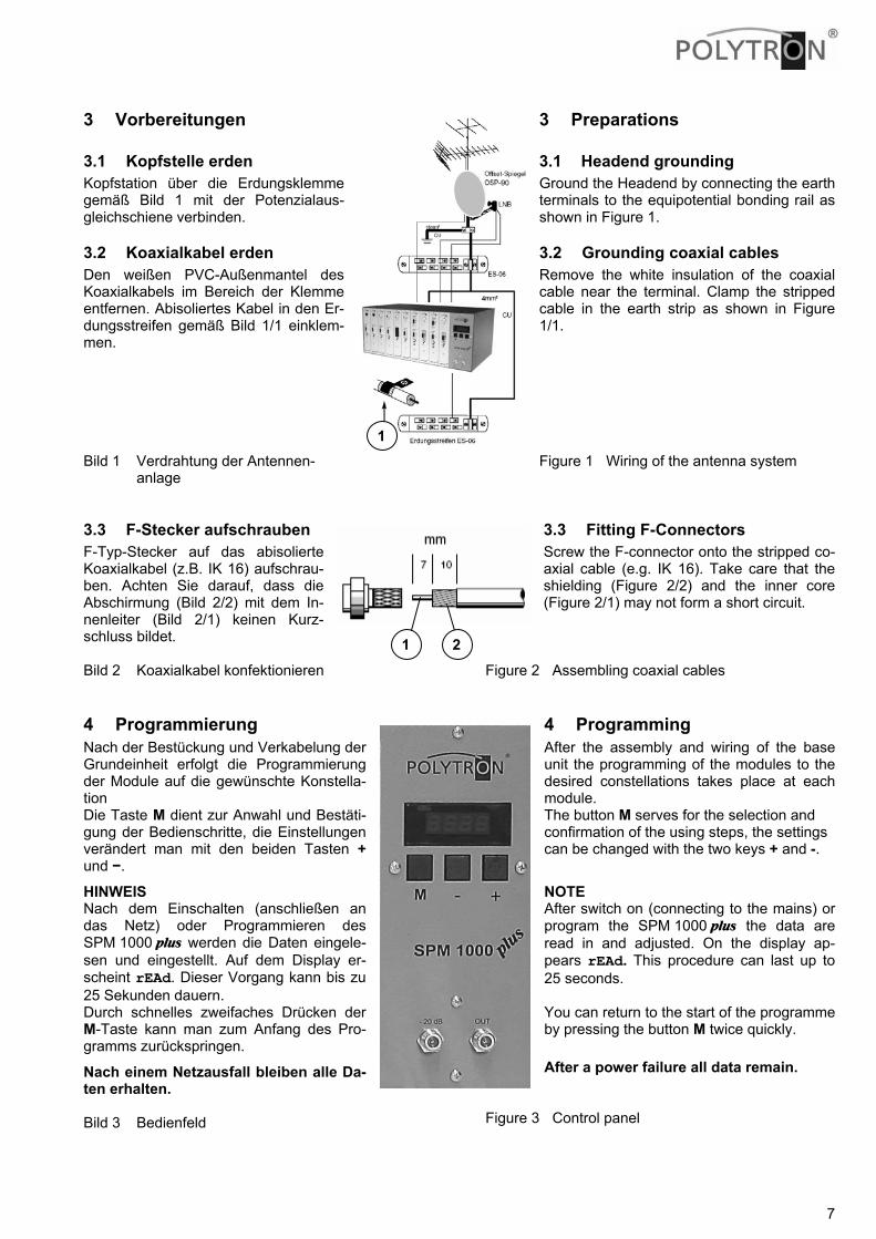
3.1 Kopfstelle erden Kopfstation über die Erdungsklemme gemäß Bild 1 mit der Potenzialaus-gleichschiene verbinden.
3.2 Koaxialkabel erden Den weißen PVC-Außenmantel des Koaxialkabels im Bereich der Klemme entfernen. Abisoliertes Kabel in den Er-dungsstreifen gemäß Bild 1/1 einklem-men. Bild 1 Verdrahtung der Antennen-
anlage 3.3 F-Stecker aufschrauben F-Typ-Stecker auf das abisolierte Koaxialkabel (z.B. IK 16) aufschrau-ben. Achten Sie darauf, dass die Abschirmung (Bild 2/2) mit dem In-nenleiter (Bild 2/1) keinen Kurz-schluss bildet. Bild 2 Koaxialkabel konfektionieren
4 Programmierung Nach der Bestückung und Verkabelung der Grundeinheit erfolgt die Programmierung der Module auf die gewünschte Konstella-tion Die Taste M dient zur Anwahl und Bestäti-gung der Bedienschritte, die Einstellungen verändert man mit den beiden Tasten + und −.
HINWEIS Nach dem Einschalten (anschließen an das Netz) oder Programmieren des SPM 1000 plus werden die Daten eingele-sen und eingestellt. Auf dem Display er-scheint rEAd. Dieser Vorgang kann bis zu 25 Sekunden dauern. Durch schnelles zweifaches Drücken der M-Taste kann man zum Anfang des Pro-gramms zurückspringen.
Nach einem Netzausfall bleiben alle Da-ten erhalten. Bild 3 Bedienfeld
3 Preparations
3.1 Headend grounding Ground the Headend by connecting the earth terminals to the equipotential bonding rail as shown in Figure 1.
3.2 Grounding coaxial cables Remove the white insulation of the coaxial cable near the terminal. Clamp the stripped cable in the earth strip as shown in Figure 1/1. Figure 1 Wiring of the antenna system
3.3 Fitting F-Connectors Screw the F-connector onto the stripped co-axial cable (e.g. IK 16). Take care that the shielding (Figure 2/2) and the inner core (Figure 2/1) may not form a short circuit.
Figure 2 Assembling coaxial cables
4 Programming After the assembly and wiring of the base unit the programming of the modules to the desired constellations takes place at each module. The button M serves for the selection and confirmation of the using steps, the settings can be changed with the two keys + and -.
NOTE After switch on (connecting to the mains) or program the SPM 1000 plus the data are read in and adjusted. On the display ap-pears rEAd. This procedure can last up to 25 seconds. You can return to the start of the programme by pressing the button M twice quickly.
After a power failure all data remain.
Figure 3 Control panel
1 2
90
1

8
4.1 Programmieren von DVB-S-Eingangs-frequenzen
Als Eingangsfrequenz der SAT-Module wird die Diffe-renz aus Transponderfrequenz und Oszillatorfre-quenz des LNBs und nicht die Transponderfrequenz programmiert. Die Berechnung der SAT-ZF-Frequenz aus der Transponderfrequenz geschieht wie in folgendem Beispiel:
Beispiel: Low Band 11406 MHz - 9750 MHz = 1656 MHz Transponder - LO-LNB* = SAT-ZF
Beispiel: High Band 12480 MHz - 10600 MHz = 1880 MHz Transponder - LO-LNB = SAT-ZF
* LO-LNB = Lokaloszillatorfrequenz des LNB-Konverters
4.2 Programmieren von DVB-T-Eingangs-frequenzen
Als Eingangsfrequenz wird die Kanalmittenfrequenz und nicht wie im analogen terrestrischen Bereich der Bildträger programmiert.
Beispiel: Kanal Bandbreite Kanalmittenfrequenz
Kanal 24 = 494 … 502 MHz = 498 MHz
4.3 Programmiersperre Im Standby-Modus (●) die Tasten M und + zur glei-chen Zeit drücken, bis der Punkt erlischt. Bei weite-rem gleichzeitigen Halten der beiden Tasten 3-mal die Taste – drücken. Nach dem Loslassen der Tasten erscheint CoFF im Display. Jetzt jeweils mit +/– zwi-schen Code on (Con) oder Code oFF (CoFF) wäh-len. Mit der Taste M die Einstellung bestätigen. Da-nach springt das Gerät automatisch in den Standby-Modus. Wurde die Programmiersperre aktiviert, (Con) meldet sich das Gerät bei Betätigen jeder Taste oder Tas-tenkombination (außer der Kodier-Kombination) mit CodE.
4.4 Wiederherstellen der Grundeinstellung (Werkseinstellung)
Im Standby-Modus (●) die Tasten M, + und – zur gleichen Zeit drücken, bis der Punkt erlischt. Nach dem Loslassen der Tasten erscheint rSt im Display. Um die Testroutine zu starten mit M bestätigen. Auf dem Display blinkt rEAd. Nun werden die werkseitigen Grundeinstellungen wieder hergestellt. Danach startet das Gerät automa-tisch neu.
4.1 Programming DVB-S Input Frequencies
As input frequency of the SAT modules the difference between transponder frequency and oscillator fre-quency of the LNBs and not the transponder fre-quency has to be programmed. The calculation of the SAT IF-frequency of the trans-ponder frequency happens as in the following exam-ple: Example: Low Band 11406 MHz - 9750 MHz = 1656 MHz Transponder - LO-LNB* = SAT-IF Example: High Band 12480 MHz - 10600 MHz = 1880 MHz Transponder - LO-LNB* = SAT-IF
* LO-LNB = local-oscillator frequency of the LNB-converter
4.2 Programming DVB-T Input Frequencies
As input frequency the channel center frequency is to be programmed and not the video carrier as in the analogous terrestrial range.
Example: Channel band width channel center frequency
Channel 24 = 494 … 502 MHz = 498 MHz
4.3 Programming Lock When in Standby mode (●), push the buttons M and + at the same time until the dot disappears. While continuously holding both buttons, press the button – 3 times. After releasing the buttons, the display shows CoFF. Choose between Code on (Con) or Code oFF (CoFF) by pressing the buttons +/–. Save your settings by pressing button M. Afterwards the unit automatically jumps into the “Standby” mode. After activation of the programme code lock (Con), the unit displays CodE when any button or button combination is pressed (except when the "code-combination” is pressed).
4.4 Activating the default setting (factory setting)
When in Standby mode (●), push the buttons M, + and – at the same time until the dot disappears. After you have released the buttons, the display shows rSt. The start of test routine is acknowledged by pressing the M button. On the display rEAd is flash-ing. Now the factory set pre-programmed settings are be restored. After that the device restarts automatically.
9
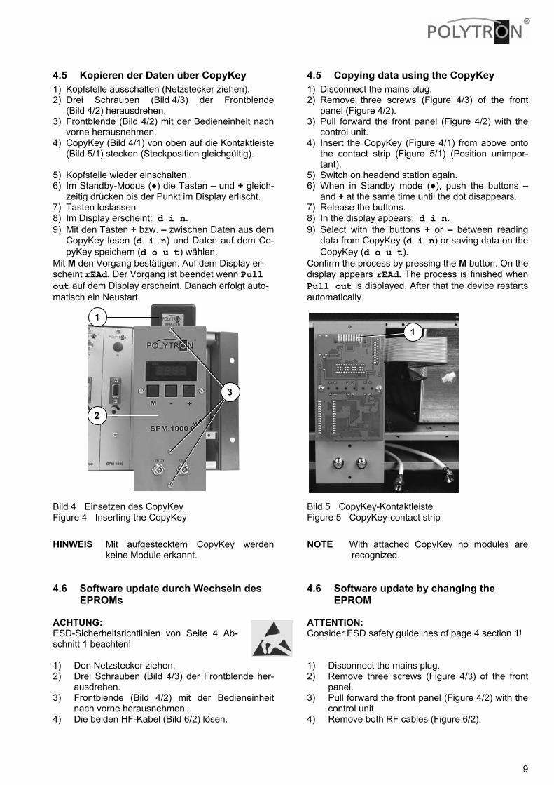
4.5 Kopieren der Daten über CopyKey 1) Kopfstelle ausschalten (Netzstecker ziehen). 2) Drei Schrauben (Bild 4/3) der Frontblende
(Bild 4/2) herausdrehen. 3) Frontblende (Bild 4/2) mit der Bedieneinheit nach
vorne herausnehmen. 4) CopyKey (Bild 4/1) von oben auf die Kontaktleiste
(Bild 5/1) stecken (Steckposition gleichgültig). 5) Kopfstelle wieder einschalten. 6) Im Standby-Modus (●) die Tasten – und + gleich-
zeitig drücken bis der Punkt im Display erlischt. 7) Tasten loslassen 8) Im Display erscheint: d i n. 9) Mit den Tasten + bzw. – zwischen Daten aus dem
CopyKey lesen (d i n) und Daten auf dem Co-pyKey speichern (d o u t) wählen.
Mit M den Vorgang bestätigen. Auf dem Display er-scheint rEAd. Der Vorgang ist beendet wenn Pull out auf dem Display erscheint. Danach erfolgt auto-matisch ein Neustart.
Bild 4 Einsetzen des CopyKey Figure 4 Inserting the CopyKey
HINWEIS Mit aufgestecktem CopyKey werden keine Module erkannt.
4.6 Software update durch Wechseln des EPROMs
ACHTUNG: ESD-Sicherheitsrichtlinien von Seite 4 Ab-schnitt 1 beachten! 1) Den Netzstecker ziehen. 2) Drei Schrauben (Bild 4/3) der Frontblende her-
ausdrehen. 3) Frontblende (Bild 4/2) mit der Bedieneinheit
nach vorne herausnehmen. 4) Die beiden HF-Kabel (Bild 6/2) lösen.
4.5 Copying data using the CopyKey 1) Disconnect the mains plug. 2) Remove three screws (Figure 4/3) of the front
panel (Figure 4/2). 3) Pull forward the front panel (Figure 4/2) with the
control unit. 4) Insert the CopyKey (Figure 4/1) from above onto
the contact strip (Figure 5/1) (Position unimpor-tant).
5) Switch on headend station again. 6) When in Standby mode (●), push the buttons –
and + at the same time until the dot disappears. 7) Release the buttons. 8) In the display appears: d i n. 9) Select with the buttons + or – between reading
data from CopyKey (d i n) or saving data on the CopyKey (d o u t).
Confirm the process by pressing the M button. On the display appears rEAd. The process is finished when Pull out is displayed. After that the device restarts automatically.
Bild 5 CopyKey-Kontaktleiste Figure 5 CopyKey-contact strip
NOTE With attached CopyKey no modules are recognized.
4.6 Software update by changing the EPROM
ATTENTION: Consider ESD safety guidelines of page 4 section 1! 1) Disconnect the mains plug. 2) Remove three screws (Figure 4/3) of the front
panel. 3) Pull forward the front panel (Figure 4/2) with the
control unit. 4) Remove both RF cables (Figure 6/2).
2
1
3
1
10
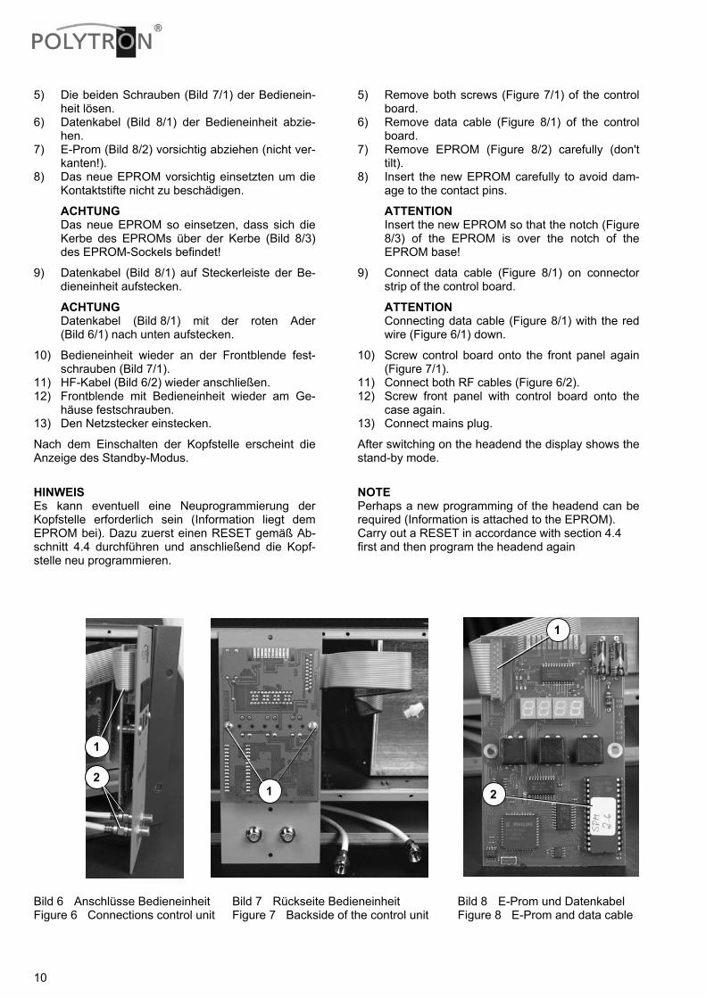
5) Die beiden Schrauben (Bild 7/1) der Bedienein-heit lösen.
6) Datenkabel (Bild 8/1) der Bedieneinheit abzie-hen.
7) E-Prom (Bild 8/2) vorsichtig abziehen (nicht ver-kanten!).
8) Das neue EPROM vorsichtig einsetzten um die Kontaktstifte nicht zu beschädigen.
ACHTUNG Das neue EPROM so einsetzen, dass sich die Kerbe des EPROMs über der Kerbe (Bild 8/3) des EPROM-Sockels befindet!
9) Datenkabel (Bild 8/1) auf Steckerleiste der Be-dieneinheit aufstecken.
ACHTUNG Datenkabel (Bild 8/1) mit der roten Ader (Bild 6/1) nach unten aufstecken.
10) Bedieneinheit wieder an der Frontblende fest-schrauben (Bild 7/1).
11) HF-Kabel (Bild 6/2) wieder anschließen. 12) Frontblende mit Bedieneinheit wieder am Ge-
häuse festschrauben. 13) Den Netzstecker einstecken.
Nach dem Einschalten der Kopfstelle erscheint die Anzeige des Standby-Modus.
HINWEIS Es kann eventuell eine Neuprogrammierung der Kopfstelle erforderlich sein (Information liegt dem EPROM bei). Dazu zuerst einen RESET gemäß Ab-schnitt 4.4 durchführen und anschließend die Kopf-stelle neu programmieren.
5) Remove both screws (Figure 7/1) of the control board.
6) Remove data cable (Figure 8/1) of the control board.
7) Remove EPROM (Figure 8/2) carefully (don't tilt).
8) Insert the new EPROM carefully to avoid dam-age to the contact pins.
ATTENTION Insert the new EPROM so that the notch (Figure 8/3) of the EPROM is over the notch of the EPROM base!
9) Connect data cable (Figure 8/1) on connector strip of the control board.
ATTENTION Connecting data cable (Figure 8/1) with the red wire (Figure 6/1) down.
10) Screw control board onto the front panel again (Figure 7/1).
11) Connect both RF cables (Figure 6/2). 12) Screw front panel with control board onto the
case again. 13) Connect mains plug.
After switching on the headend the display shows the stand-by mode.
NOTE Perhaps a new programming of the headend can be required (Information is attached to the EPROM). Carry out a RESET in accordance with section 4.4 first and then program the headend again
Bild 6 Anschlüsse Bedieneinheit Bild 7 Rückseite Bedieneinheit Bild 8 E-Prom und Datenkabel Figure 6 Connections control unit Figure 7 Backside of the control unit Figure 8 E-Prom and data cable
1
1
2 2
1

11
5 Maße und Anschlusszeichnungen SPM 1000 plus
Bild 9 Bedien- und Anzeigeelemente, Anschlüsse 1 Eingänge 2 Steckplätze für die Module 3 Display für Programmierung und Anschluss für
den CopyKey(Bedienfeld abnehmbar.). 4 HF-Ausgang 5 Testausgang (ca. -20 dB) 6 Pegelsteller für den jeweiligen Kanal 7 Audio-/Video-Eingangsbuchse
Bild 10 Bemaßung der Montagewinkel Der Netzanschluss 230 VAC befindet sich auf der Rückseite der Grundeinheit.
5 Dimensions and Connection draw-ings SPM1000 plus
Figure 9 Control- and Display elements, connec-tions
1 Inputs 2 Module slots 3 Display for programming and connection for
CopyKey (Control panel removable). 4 RF Output 5 Test output (ca. -20 dB) 6 Level regulators for the corresponding channel 7 Sub-D sockets (AV input)
Figure 10 Dimensions for the fixing brackets The mains connection 230 VAC is on the back of the base unit.
406 mm
101 mm
6
3
4 5
1
7
2
12
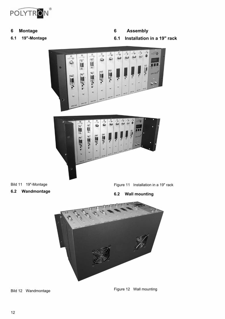
6 Montage 6.1 19"-Montage
Bild 11 19"-Montage
6.2 Wandmontage
Bild 12 Wandmontage
6 Assembly 6.1 Installation in a 19" rack
Figure 11 Installation in a 19" rack
6.2 Wall mounting
Figure 12 Wall mounting
13
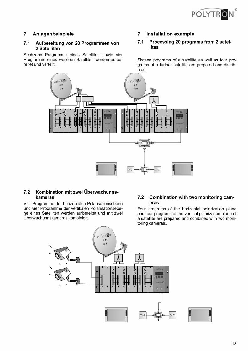
7 Anlagenbeispiele
7.1 Aufbereitung von 20 Programmen von 2 Satelliten
Sechzehn Programme eines Satelliten sowie vier Programme eines weiteren Satelliten werden aufbe-reitet und verteilt.
7.2 Kombination mit zwei Überwachungs-kameras
Vier Programme der horizontalen Polarisationsebene und vier Programme der vertikalen Polarisationsebe-ne eines Satelliten werden aufbereitet und mit zwei Überwachungskameras kombiniert.
7 Installation example 7.1 Processing 20 programs from 2 satel-
lites Sixteen programs of a satellite as well as four pro-grams of a further satellite are prepared and distrib-uted.
7.2 Combination with two monitoring cam-eras
Four programs of the horizontal polarization plane and four programs of the vertical polarization plane of a satellite are prepared and combined with two moni-toring cameras..
SPMO
SPMO
14
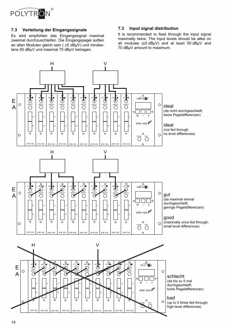
7.3 Verteilung der Eingangssignale Es wird empfohlen das Eingangssignal maximal zweimal durchzuschleifen. Die Eingangspegel sollten an allen Modulen gleich sein ( ±5 dBµV) und mindes-tens 50 dBµV und maximal 70 dBµV betragen.
7.3 Input signal distribution It is recommended to feed through the input signal maximally twice. The input levels should be alike on all modules (±5 dBµV) and at least 50 dBµV and 70 dBµV amount to maximum.
gut (da maximal einmal durchgeschleift; geringe Pegeldifferenzen) good (maximally once fed through; small level differences)
schlecht (da bis zu 5 mal durchgeschleift; hohe Pegeldifferenzen) bad (up to 5 times fed through; high level differences)
ideal (da nicht durchgeschleift; keine Pegeldifferenzen) ideal (not fed through no level differences)
SPM 1000 SPM 1000 SPM 1000 SPM 1000 SPM 1000 SPM 1000 SPM 1000 SPM 1000 SPM 1000 SPM 1000
-20 dB OUT
IN/OUT IN/OUT IN/OUT IN/OUT IN/OUT IN/OUT IN/OUT IN/OUT IN/OUT IN/OUT
A B
A B
A B
A B
A B
A B
A B
A B
A B
A B
H V
E A
SPM 1000
M - +
SPM 1000 SPM 1000 SPM 1000 SPM 1000 SPM 1000 SPM 1000 SPM 1000 SPM 1000 SPM 1000 SPM 1000
-20 dB OUT
IN/OUT IN/OUT IN/OUT IN/OUT IN/OUT IN/OUT IN/OUT IN/OUT IN/OUT IN/OUT
A B
A B
A B
A B
A B
A B
A B
A B
A B
A B
H V
E A
SPM 1000
M - +
SPM 1000 SPM 1000 SPM 1000 SPM 1000 SPM 1000 SPM 1000 SPM 1000 SPM 1000 SPM 1000 SPM 1000
-20 dB OUT
IN/OUT IN/OUT IN/OUT IN/OUT IN/OUT IN/OUT IN/OUT IN/OUT IN/OUT IN/OUT
A B
A B
A B
A B
A B
A B
A B
A B
A B
A B
H V
E A
SPM 1000
M - +
15
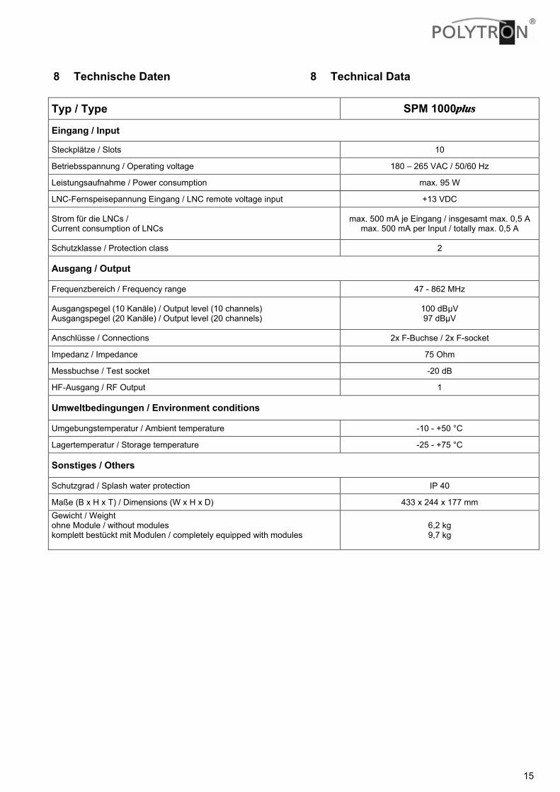
8 Technische Daten 8 Technical Data Typ / Type SPM 1000plus
Eingang / Input
Steckplätze / Slots 10
Betriebsspannung / Operating voltage 180 – 265 VAC / 50/60 Hz
Leistungsaufnahme / Power consumption max. 95 W
LNC-Fernspeisepannung Eingang / LNC remote voltage input +13 VDC
Strom für die LNCs / Current consumption of LNCs
max. 500 mA je Eingang / insgesamt max. 0,5 A max. 500 mA per Input / totally max. 0,5 A
Schutzklasse / Protection class 2
Ausgang / Output
Frequenzbereich / Frequency range 47 - 862 MHz
Ausgangspegel (10 Kanäle) / Output level (10 channels) Ausgangspegel (20 Kanäle) / Output level (20 channels)
100 dBµV 97 dBµV
Anschlüsse / Connections 2x F-Buchse / 2x F-socket
Impedanz / Impedance 75 Ohm
Messbuchse / Test socket -20 dB
HF-Ausgang / RF Output 1
Umweltbedingungen / Environment conditions
Umgebungstemperatur / Ambient temperature -10 - +50 °C
Lagertemperatur / Storage temperature -25 - +75 °C
Sonstiges / Others
Schutzgrad / Splash water protection IP 40
Maße (B x H x T) / Dimensions (W x H x D) 433 x 244 x 177 mm Gewicht / Weight ohne Module / without modules komplett bestückt mit Modulen / completely equipped with modules
6,2 kg 9,7 kg

Polytron-Vertrieb GmbH
Postfach 10 02 33
75313 Bad Wildbad
Zentrale/Bestellannahme H.Q. Order department + 49 (0) 70 81/1702 - 0
Technische Hotline Technical hotline + 49 (0) 70 81/1702 - 12
Telefax + 49 (0) 70 81) 1702 - 50
Internet http://www.polytron.de
eMail [email protected]
Technische Änderungen vorbehalten Subject to change without prior notice Copyright © Polytron-Vertrieb GmbH