Projektgruppe fu¨r ein Experiment am International … · • Koordinierung und Vorantreiben der...
38
Projektgruppe f¨ ur ein Experiment am International Linear Collider (ILC) (Statusbericht, November 2007) Outline: • Organisatorisches zur ILC-Projektgruppe • Neues von ILC und den Detektor-Konzepten • Experimentelle Wiener Beitr¨ age: – Vertex Reconstruction (RAVE/VERTIGO) – Detector Optimization Tool (LiC Toy) – Detektor R&D: Mitarbeit am SiLC-Projekt = ⇒ siehe separaten Bericht von Th. Bergauer Winfried Mitaroff HEPHY Projektbericht, 19. November 2007
Transcript of Projektgruppe fu¨r ein Experiment am International … · • Koordinierung und Vorantreiben der...
Projektgruppe fur ein Experiment am
International Linear Collider (ILC)(Statusbericht, November 2007)
Outline:
• Organisatorisches zur ILC-Projektgruppe
• Neues von ILC und den Detektor-Konzepten
• Experimentelle Wiener Beitrage:
– Vertex Reconstruction (RAVE/VERTIGO)
– Detector Optimization Tool (LiC Toy)– Detektor R&D: Mitarbeit am SiLC-Projekt =⇒ siehe separaten Bericht von Th. Bergauer
Winfried Mitaroff HEPHY Projektbericht, 19. November 2007

Reminiszenzen & Personalstand
Der Grundungsauftrag:
• Koordinierung und Vorantreiben der experimentellen Aktivitaten (Hard- und Software) mit dem Ziel
der Beteiligung an einem Experiment am ILC;
• Grundung der Projektgruppe auf der Vorstandsitzung am 29. November 2005, Beginn mit Janner 2006; schonvorher experimentelle und organisatorische Aktivitaten:
– RAVE/VERTIGO (erstmals prasentiert am 1st ECFA Workshop ..., November 2003 in Montpellier),
– SiLC R&D-Projekt (erste Kontakte mit Aurore Savoy-Navarro am LCWS, April 2004 in Paris),
– Ausrichtung des 3rd ECFA Workshop on Physics & Detectors for ILC, 14–17/18. Nov. 2005 in Wien;
• Die Arbeit erfolgt in enger Zusammenarbeit mit den Fachbereichen ASE und HLD, spater auch EL-II.
Wiener Mitarbeiter 2007:
• W. Mitaroff (Projektleiter) und M. Regler (WV-Drittel),
• Th. Bergauer und M. Krammer (Fachbereich HLD),
• R. Fruhwirth und W. Waltenberger (Fachbereich ASE);
• Studenten mit ggf. DV bzw. aquivalentem WV:
– M. Valentan (bis Feb) und R. Hofler (Feb–Aug),
– H.V. Riedel (Jan–Jul) und B. Pflugfelder (Apr–Aug);
• Diplomanden & Dissertanten (ab Herbst 2007):
– M. Valentan (ab Aug) und F. Moser (ab Okt): Diplomanden in ASE,
– Th. Bergauer und St. Hansel : Dissertanten im Fachbereich HLD.
Winfried Mitaroff HEPHY Projektbericht, 19. November 2007
Internationale Wahrnehmung
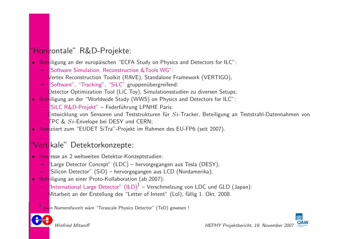
“Horizontale” R&D-Projekte:
• Beteiligung an der europaischen “ECFA Study on Physics and Detectors for ILC”:
– “Software Simulation, Reconstruction &Tools WG”:Vertex Reconstruction Toolkit (RAVE), Standalone Framework (VERTIGO),
– “Software”, “Tracking”, “SiLC” gruppenubergreifend:Detector Optimization Tool (LiC Toy), Simulationsstudien zu diversen Setups;
• Beteiligung an der “Worldwide Study (WWS) on Physics and Detectors for ILC”:
– “SiLC R&D-Projekt” – Federfuhrung LPNHE Paris:
Entwicklung von Sensoren und Teststrukturen fur Si-Tracker, Beteiligung an Teststrahl-Datennahmen vonTPC & Si-Envelope bei DESY und CERN;
• Assoziiert zum “EUDET SiTra”-Projekt im Rahmen des EU-FP6 (seit 2007).
“Vertikale” Detektorkonzepte:
• Interesse an 2 weltweiten Detektor-Konzeptstudien:
– “Large Detector Concept” (LDC) – hervorgegangen aus Tesla (DESY),
– “Silicon Detector” (SiD) – hervorgegangen aus LCD (Nordamerika);
• Beteiligung an einer Proto-Kollaboration (ab 2007):
– “International Large Detector” (ILD)1 – Verschmelzung von LDC und GLD (Japan):Mitarbeit an der Erstellung des “Letter of Intent” (LoI), fallig 1. Okt. 2008.
1mein Namensfavorit ware “Terascale Physics Detector” (TeD) gewesen !
Winfried Mitaroff HEPHY Projektbericht, 19. November 2007
Internationale Wahrnehmung
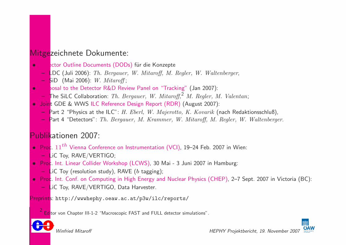
Mitgezeichnete Dokumente:
• Detector Outline Documents (DODs) fur die Konzepte
– LDC (Juli 2006): Th. Bergauer, W. Mitaroff, M. Regler, W. Waltenberger,
– SiD (Mai 2006): W. Mitaroff ;
• Proposal to the Detector R&D Review Panel on “Tracking” (Jan 2007):
– The SiLC Collaboration: Th. Bergauer, W. Mitaroff,2 M. Regler, M. Valentan;
• Joint GDE & WWS ILC Reference Design Report (RDR) (August 2007):
– Part 2 “Physics at the ILC”: H. Eberl, W. Majerotto, K. Kovarik (nach Redaktionsschluß),
– Part 4 “Detectors”: Th. Bergauer, M. Krammer, W. Mitaroff, M. Regler, W. Waltenberger.
Publikationen 2007:
• Proc. 11th Vienna Conference on Instrumentation (VCI), 19–24 Feb. 2007 in Wien:
– LiC Toy, RAVE/VERTIGO;
• Proc. Int. Linear Collider Workshop (LCWS), 30 Mai - 3 Juni 2007 in Hamburg:
– LiC Toy (resolution study), RAVE (b tagging);
• Proc. Int. Conf. on Computing in High Energy and Nuclear Physics (CHEP), 2–7 Sept. 2007 in Victoria (BC):
– LiC Toy, RAVE/VERTIGO, Data Harvester.
Preprints: http://wwwhephy.oeaw.ac.at/p3w/ilc/reports/
2Editor von Chapter III-1-2 “Macroscopic FAST and FULL detector simulations”.
Winfried Mitaroff HEPHY Projektbericht, 19. November 2007

Neues von ILC und den Detektoren
GDE & WWS “Reference Design Report” (RDR):Endversion herausgegeben im August 2007. Inkludiert nunmehr auch den “Detector Conceptual Report” (DCR) furPhysik & Detektoren. Besteht aus 4 Teilen und einem Begleitdokument:
• Part 1: Executive Summary (Editors J. Brau, Y. Okada, N. Walker),
• Part 2: Physics at the ILC
(Editors A. Djouadi, J. Lykken, K. Monig, Y. Okada, M. Oreglia, S. Yamashita),
• Part 3: Accelerator (Editors N. Phinney, N. Toge, N. Walker),
• Part 4: Detectors (Editors T. Behnke, Ch. Damerell, J. Jaros, A. Miyamoto),
• Companion document: The ILC – Gateway to the Quantum Universehttp://www.linearcollider.org/gateway/
WWS “ILC Detector R&D Review Panel”:Chairman Ch. Damerell. Reviews: Tracking (Feb. 07 – massive Beteiligung von SiLC), Calorimetry (Juni 07),Vertexing (Okt. 07), Particle ID, Muons, Solenoids, Beamdiagnostik, DAQ (Marz 08).
Nachste große Meilensteine:
• Aufruf zu Letters of Intent (LoI) fur die Experimente: Einreichfrist 1. Oktober 2008;
• Engineering Design Reports (EDR): geplant 2010 fur
– den Beschleuniger (Grundlage fur die Errichtungsentscheidung),
– die Detektoren der beiden ausgewahlten Experimente.
Winfried Mitaroff HEPHY Projektbericht, 19. November 2007
Neues von ILC und den Detektoren
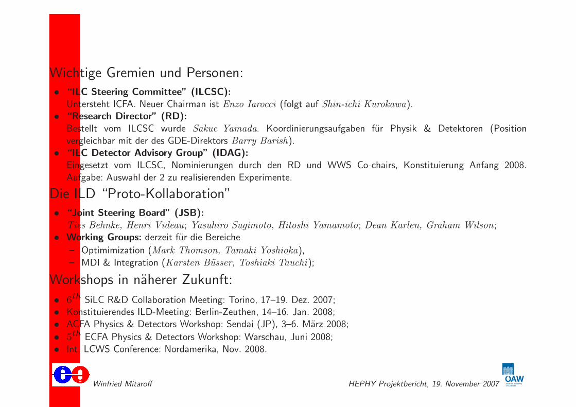
Wichtige Gremien und Personen:
• “ILC Steering Committee” (ILCSC):Untersteht ICFA. Neuer Chairman ist Enzo Iarocci (folgt auf Shin-ichi Kurokawa).
• “Research Director” (RD):
Bestellt vom ILCSC wurde Sakue Yamada. Koordinierungsaufgaben fur Physik & Detektoren (Positionvergleichbar mit der des GDE-Direktors Barry Barish).
• “ILC Detector Advisory Group” (IDAG):Eingesetzt vom ILCSC, Nominierungen durch den RD und WWS Co-chairs, Konstituierung Anfang 2008.
Aufgabe: Auswahl der 2 zu realisierenden Experimente.
Die ILD “Proto-Kollaboration”
• “Joint Steering Board” (JSB):
Ties Behnke, Henri Videau; Yasuhiro Sugimoto, Hitoshi Yamamoto; Dean Karlen, Graham Wilson;• Working Groups: derzeit fur die Bereiche
– Optimimization (Mark Thomson, Tamaki Yoshioka),
– MDI & Integration (Karsten Busser, Toshiaki Tauchi);
Workshops in naherer Zukunft:
• 6th SiLC R&D Collaboration Meeting: Torino, 17–19. Dez. 2007;• Konstituierendes ILD-Meeting: Berlin-Zeuthen, 14–16. Jan. 2008;• ACFA Physics & Detectors Workshop: Sendai (JP), 3–6. Marz 2008;
• 5th ECFA Physics & Detectors Workshop: Warschau, Juni 2008;• Int. LCWS Conference: Nordamerika, Nov. 2008.
Winfried Mitaroff HEPHY Projektbericht, 19. November 2007
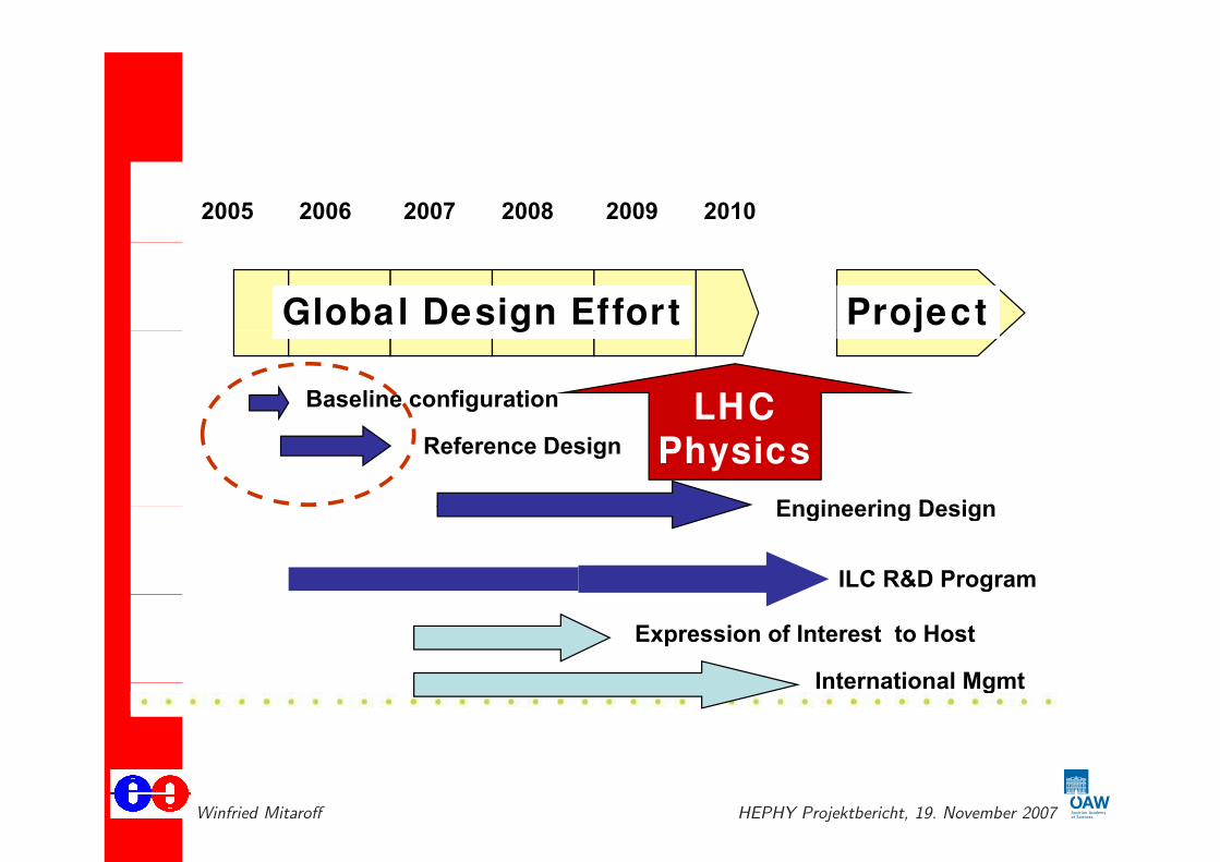
“Global Design Effort” (GDE) Schedule
2005 2006 2007 2008 2009 2010
Global Design Effort Projectg j
Baseline configuration LHCReference Design
Engineering Design
LHCPhysics
ILC R&D Program
Engineering Design
Expression of Interest to Host
International MgmtInternational Mgmt
Winfried Mitaroff HEPHY Projektbericht, 19. November 2007

Reference Design Report (RDR) part 3
– 11km SC linacs operating at 31.5 MV/m for 500 GeV
– Centralized injectorj
• Circular damping rings for electrons and positrons
• Undulator-based positron source
– Single IR with 14 mrad crossing angle
– Dual tunnel configuration for safety and availability
22-Oct-07
ALCPG07/GDE Fermilab Global Design Effort 5
Winfried Mitaroff HEPHY Projektbericht, 19. November 2007

Fermilab “pre-construction plan”
Central Area fits inside the Fermilab boundary
B d
~ 5.5 km
~ 5.5 km Site Characterization
of the Central Area can
be done
~ Boundary
of Fermilab
be done
Winfried Mitaroff HEPHY Projektbericht, 19. November 2007
Reference Design Report (RDR) part 3
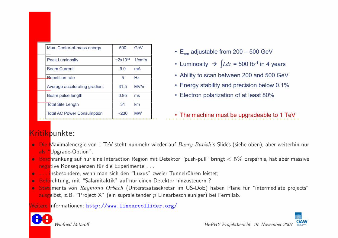
Max. Center-of-mass energy 500 GeV
Peak Luminosity ~2x1034 1/cm2s
Beam Current 9.0 mA
Repetition rate 5 HzRepetition rate 5 Hz
Average accelerating gradient 31.5 MV/m
Beam pulse length 0.95 ms
Total Site Length 31 km
Total AC Power Consumption ~230 MW
22-Oct-07 Global Design Effort 6
Total AC Power Consumption 230 MW
• E adjustable from 200 500 GeV• Ecm adjustable from 200 – 500 GeV
• Luminosity Ldt = 500 fb-1 in 4 years• Luminosity Ldt = 500 fb in 4 years
• Ability to scan between 200 and 500 GeVAbility to scan between 200 and 500 GeV
• Energy stability and precision below 0.1%
• Electron polarization of at least 80%
• The machine must be upgradeable to 1 TeV22-Oct-07 Global Design Effort 4
• The machine must be upgradeable to 1 TeV
Kritikpunkte:
• Die Maximalenergie von 1 TeV steht nunmehr wieder auf Barry Barish’s Slides (siehe oben), aber weiterhin nurals “Upgrade-Option”.
• Beschrankung auf nur eine Interaction Region mit Detektor “push-pull” bringt< 5% Ersparnis, hat aber massivenegative Konsequenzen fur die Experimente . . .
• . . . insbesondere, wenn man sich den “Luxus” zweier Tunnelrohren leistet;
• Befurchtung, mit “Salamitaktik” auf nur einen Detektor hinzusteuern ?
• Statements von Raymond Orbach (Unterstaatssekretar im US-DoE) haben Plane fur “intermediate projects”ausgelost, z.B. “Project X” (ein supraleitender p Linearbeschleuniger) bei Fermilab.
Weitere Informationen: http://www.linearcollider.org/
Winfried Mitaroff HEPHY Projektbericht, 19. November 2007

The main linac’s SC cavities
4th generationg
prototype ILC
cryomodule
TESLA cryomodule
Producing Cavities
Cavity Shape
Obtaining Gradientsingle cells
Winfried Mitaroff HEPHY Projektbericht, 19. November 2007
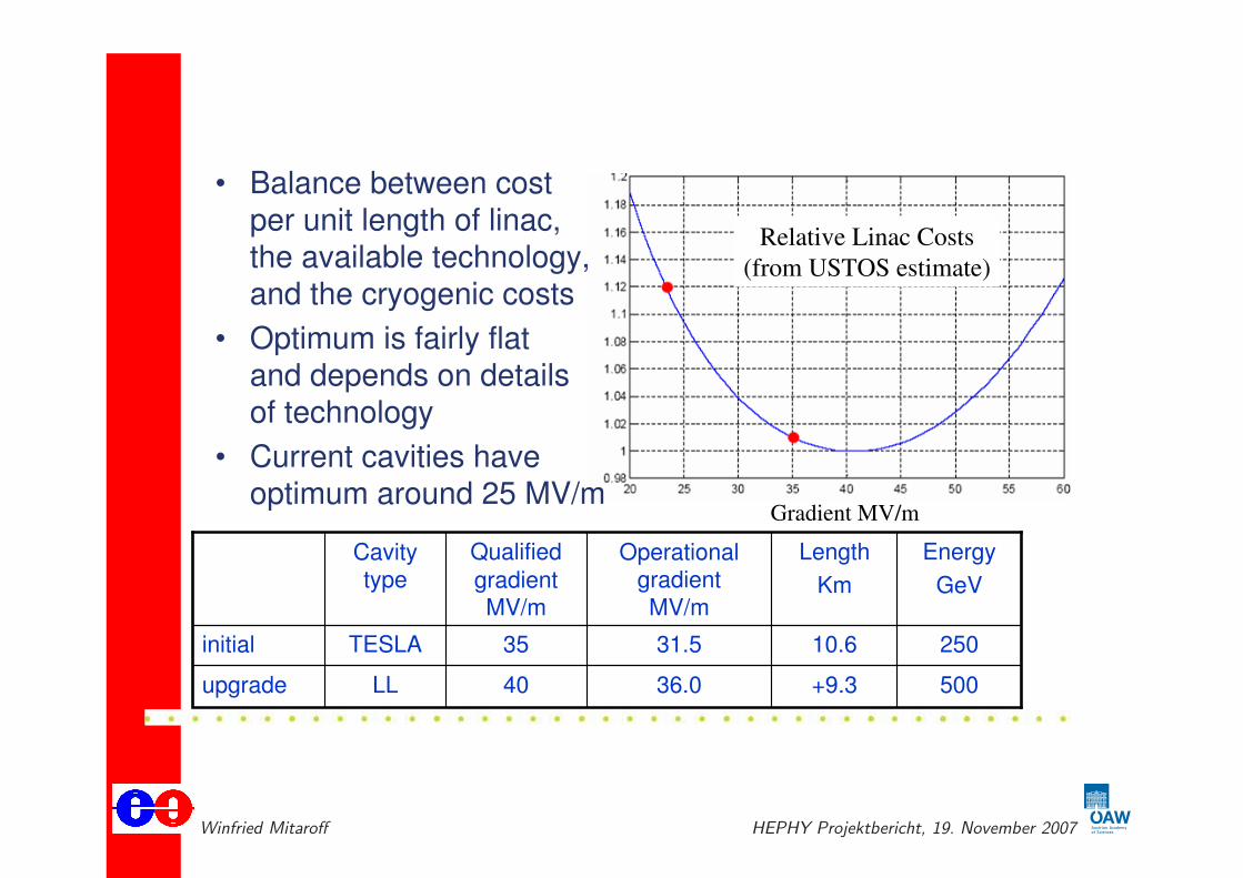
How costs scale with the gradient
• Balance between cost
per unit length of linac, the available technology, and the cryogenic costs
• Optimum is fairly flatand depends on detailsof technology
• Current cavities haveoptimum around 25 MV/m
Gradient MV/m
Relative Linac Costs
(from USTOS estimate)
Cavitytype
Qualified
gradientMV/m
Operationalgradient
MV/m
Length
Km
Energy
GeV
initial TESLA
LL
35 31.5 10.6 250
upgrade 40 36.0 +9.3 500
Winfried Mitaroff HEPHY Projektbericht, 19. November 2007

First cost estimate of accelerator
Summary
RDR “Value” CostsThe reference design was “frozen” as of 1-Dec-06 for the purpose of
d i th RDR i l di t
Total Value Cost (FY07)
producing the RDR, including costs.
It is important to recognize this is a Total Value Cost (FY07)
4.80 B ILC Units Shared
+
snapshot and the design will continue to evolve, due to results of the R&D, accelerator studies and +
1.82 B Units Site Specific
,value engineering
The value costs have already been+
14.1 K person-years
The value costs have already beenreviewed extensively
• 3 day “internal review” in Dec(“explicit” labor = 24.0 M person-hrs
@ 1,700 hrs/yr)
1 ILC Unit = $ 1 (2007)
• ILCSC MAC review in Jan•International cost review in Spring
V l 6 62 B ILC U it1 ILC Unit = $ 1 (2007)
Value = 6.62 B ILC Units
Erste Kostenabschatzung: 6.62 G$ plus 14.1 k Personenjahre (1.4 G$) = ca. 8 G$ = ca. 6.5 G¿.
Winfried Mitaroff HEPHY Projektbericht, 19. November 2007
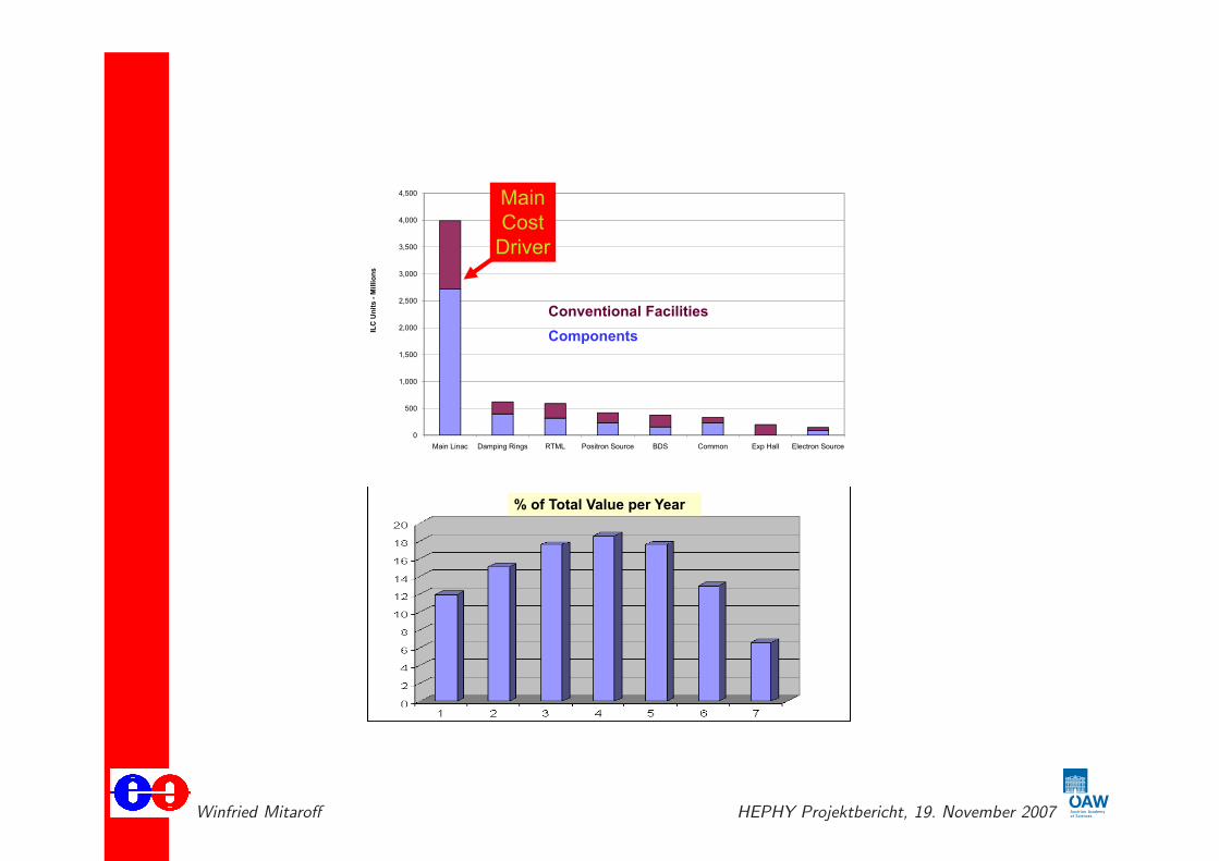
First cost estimate: details
4 000
4,500 Main
Cost3,500
4,000
s
Cost
Driver
2,500
3,000
Un
its
-M
illi
on
s
Conventional Facilities
1,500
2,000ILC
Components
500
1,000
0
Main Linac Damping Rings RTML Positron Source BDS Common Exp Hall Electron Source
% of Total Value per Year
We are not usin inte rated cost/schedule
Winfried Mitaroff HEPHY Projektbericht, 19. November 2007
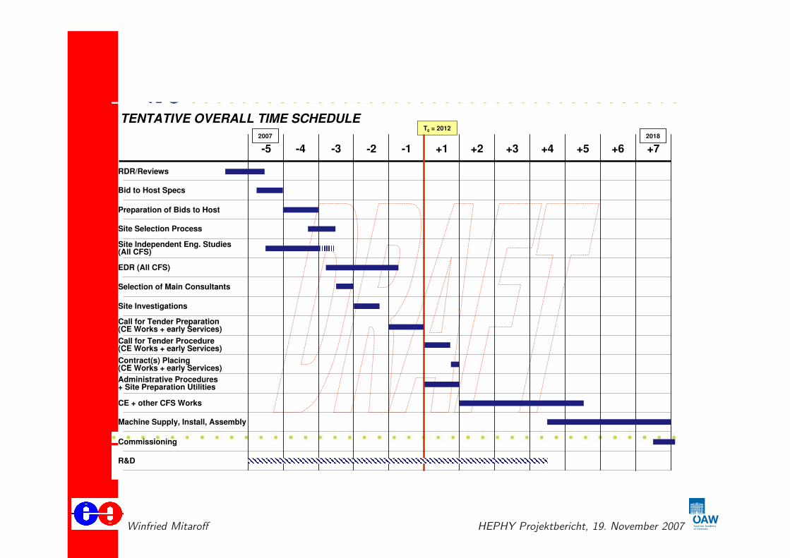
ILC optimistic time schedule (Feb 2007)
7-Feb-07
GDE/ACFA Closing Beijing
Global Design Effort 14
-5 -4 -3 -1 +1 +2 +3 +4 +5 +6 +7
T0 = 2012
2007
-2
RDR/Reviews
Bid to Host Specs
Preparation of Bids to Host
Site Selection Process
EDR (All CFS)
Site Investigations
Call for Tender Preparation (CE Works + early Services)
Call for Tender Procedure (CE Works + early Services)
Contract(s) Placing(CE Works + early Services)
Administrative Procedures+ Site Preparation Utilities
CE + other CFS Works
Machine Supply, Install, Assembly
Commissioning
R&D
TENTATIVE OVERALL TIME SCHEDULE
2018
Selection of Main Consultants
Site Independent Eng. Studies(All CFS)
Winfried Mitaroff HEPHY Projektbericht, 19. November 2007

Vergleich des Untergrunds LHC – ILC
ILC Environmental ChallengesILC is benign compared to LHC, …
LHC ILC• Event Rates
Inclusive 1 GHz (min bias) 1 kHz ( ->hadrons)
• Bunch Crossings25ns (40 Mhz) 300ns (15kHz)DC 0.5% Duty Factor
• TriggeringLevel 1 & 2 40MHz -> 1kHz No Hardware TriggerLevel 3 ~100 Hz Software ~100 Hz Software
• Radiation Field 1-100 MRad/Yr 10 kRad/Yr
• OccupancyPer bunch 23 min bias 0.3 ->hadrons
100 tracks 2 tracks
Winfried Mitaroff HEPHY Projektbericht, 19. November 2007

Vertexdetektor Occupancy bei ILCVertex Readout Challenge
• Bunch train structure can swamp the inner layers of the VXD
with beamstrahlung-induced pair backgrounds.
• To reduce occupancies to 5 mm-2, the detector livetime must
be reduced. Faster effective readout speeds are required.
• Getting enough power in for faster readout, taking enough heat
out, are real challenges for “massless” detectors!
Winfried Mitaroff HEPHY Projektbericht, 19. November 2007

The 4 detector conceptsEvolving Designs for ILC Experiments
SiD LDC GLD
•Solenoid Designs B=5,4,3 Tesla
•Si vs TPC Tracking
•“Particle Flow” Calorimeters
4th
•Dual Solenoid
•Compensating Cal
•TPC Tracking
ILD
Winfried Mitaroff HEPHY Projektbericht, 19. November 2007
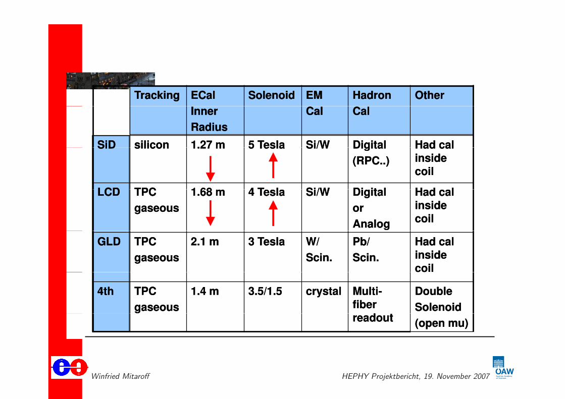
Detector concepts: details
TrackingTracking ECalECal SolenoidSolenoid EM EM HadronHadron OtherOther
InnerInner
RadiusRadius
CalCal CalCal
SiDSiD siliconsilicon 1.27 m1.27 m 5 Tesla5 Tesla Si/WSi/W DigitalDigital Had calHad calSiDSiD siliconsilicon 1.27 m1.27 m 5 Tesla5 Tesla Si/WSi/W DigitalDigital
(RPC..)(RPC..)
Had calHad cal
insideinside
coilcoil
LCDLCD TPCTPC 1 681 68 4 T l4 T l Si/WSi/W Di it lDi it l H d lH d lLCDLCD TPCTPC
gaseousgaseous
1.68 m1.68 m 4 Tesla4 Tesla Si/WSi/W DigitalDigital
oror
AnalogAnalog
Had calHad cal
insideinside
coilcoil
GLDGLD TPCTPC
gaseousgaseous
2.1 m2.1 m 3 Tesla3 Tesla W/W/
Scin.Scin.
Pb/Pb/
Scin.Scin.
Had cal Had cal
insideinside
coilcoil
4th4th TPCTPC
gaseousgaseous
1.4 m1.4 m 3.5/1.53.5/1.5 crystalcrystal MultiMulti--
fiberfiber
d td t
DoubleDouble
SolenoidSolenoidreadoutreadout
(open mu)(open mu)
Winfried Mitaroff HEPHY Projektbericht, 19. November 2007
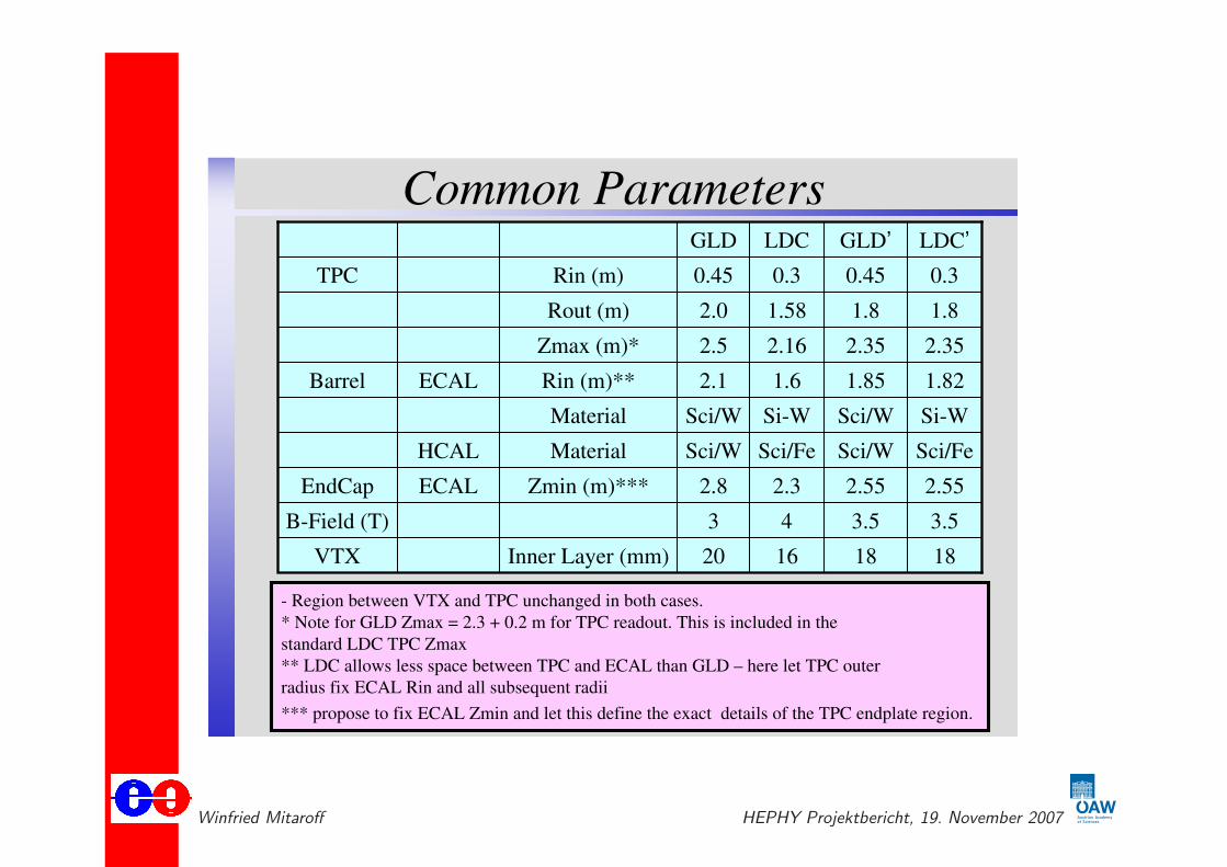
Merging the LDC and GLD concepts
10/23/2007 ILD Meeting 9
Common ParametersGLD LDC GLD’ LDC’
TPC Rin (m) 0.45 0.3 0.45 0.3
Rout (m) 2.0 1.58 1.8 1.8
Zmax (m)* 2.5 2.16 2.35 2.35
Barrel ECAL Rin (m)** 2.1 1.6 1.85 1.82
Material Sci/W Si-W Sci/W Si-W
HCAL Material Sci/W Sci/Fe Sci/W Sci/Fe
EndCap ECAL Zmin (m)*** 2.8 2.3 2.55 2.55
B-Field (T) 3 4 3.5 3.5
VTX Inner Layer (mm) 20 16 18 18
- Region between VTX and TPC unchanged in both cases.
* Note for GLD Zmax = 2.3 + 0.2 m for TPC readout. This is included in the
standard LDC TPC Zmax
** LDC allows less space between TPC and ECAL than GLD – here let TPC outer
radius fix ECAL Rin and all subsequent radii
*** propose to fix ECAL Zmin and let this define the exact details of the TPC endplate region.
Winfried Mitaroff HEPHY Projektbericht, 19. November 2007
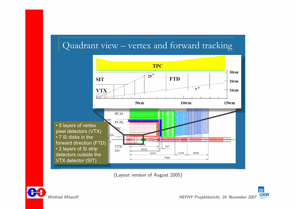
Example: the LDC detector’s tracking
Quadrant view – vertex and forward tracking
• 5 layers of vertex
pixel detectors (VTX)
• 7 Si disks in the
forward direction (FTD)
• 2 layers of Si strip
detectors outside the
VTX detector (SIT)
(Layout version of August 2005)
Winfried Mitaroff HEPHY Projektbericht, 19. November 2007

“Marlin”: C++ based software framework
�� ������ ���������������� ������ ��������������
���#�!����������������������� ��������������
$�%&"�'�����������������
����"���������������������
(#))%� (%&��*
��'�� &��� %��$��������
����
Winfried Mitaroff HEPHY Projektbericht, 19. November 2007

“org.lcsim”: Java based software framework
org.lcsim ALCPG 2007
T.Johnson 4/23
Overview:Overview: ““SLIC + SLIC + org.lcsimorg.lcsim”” FrameworkFramework
StdHepEvents SLIC
LCDDXML
LCIOEvents
Geom
Converter
CompactXML
org.lcsim
JAS3
WIRED4
AIDA HepRepXML
Conditions
Software
PackageData Format
User Analysis
Drivers
Winfried Mitaroff HEPHY Projektbericht, 19. November 2007

First detector cost estimates
Based on the work by the costing panel.
They estimated the costs in light of the GDE costing rule, and attempt t id tif b kd d th t d ito identify breakdown and the cost drivers
Calorimeters and magnets are cost drivers.
The cost breakdowns are different according to how to categorize,for example, separation of M&S and man power costs.
Overall, there is reasonable agreement among the three concept estimates. , g g pThe total cost lies in the range of 400-500M$ with ~20% error
Winfried Mitaroff HEPHY Projektbericht, 19. November 2007
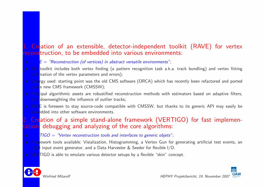
RAVE/VERTIGO – main features
1. Creation of an extensible, detector-independent toolkit (RAVE) for vertexreconstruction, to be embedded into various environments:
• RAVE = “Reconstruction (of vertices) in abstract versatile environments”;
• The toolkit includes both vertex finding (a pattern recognition task a.k.a. track bundling) and vertex fitting
(estimation of the vertex parameters and errors);
• Synergy used: starting point was the old CMS software (ORCA) which has recently been refactored and ported
to the new CMS framework (CMSSW);
• Principal algorithmic assets are robustified reconstruction methods with estimators based on adaptive filters,
thus downweighting the influence of outlier tracks;
• RAVE is foreseen to stay source-code compatible with CMSSW, but thanks to its generic API may easily be
embedded into other software environments.
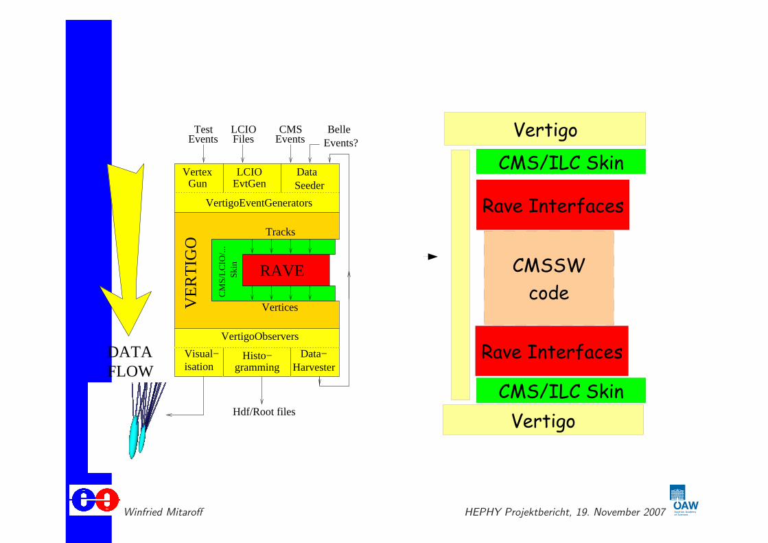
2. Creation of a simple stand-alone framework (VERTIGO) for fast implemen-tation, debugging and analyzing of the core algorithms:
• VERTIGO = “Vertex reconstruction tools and interfaces to generic objets”;
• Framework tools available: Visialization, Histogramming, a Vertex Gun for generating artificial test events, an
LCIO input event generator, and a Data Harvester & Seeder for flexible I/O.
• VERTIGO is able to emulate various detector setups by a flexible “skin” concept.
Winfried Mitaroff HEPHY Projektbericht, 19. November 2007
Example of using the RAVE toolkit
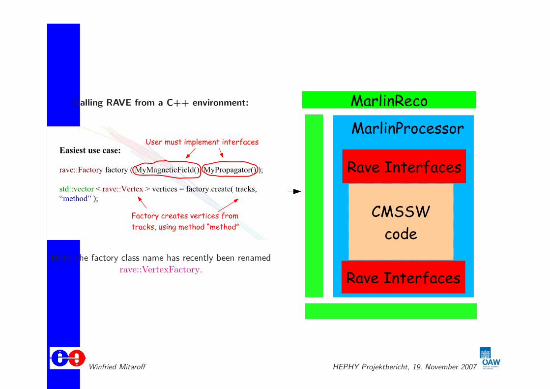
Calling RAVE from a C++ environment:
���������������
������������������ ��������������� ������������ ����
��������������������������������������������������� ����� ���
!"��#�$���
����������%�����������
������������&����������
���$� ������������.����/
Note: the factory class name has recently been renamedrave::VertexFactory.
Winfried Mitaroff HEPHY Projektbericht, 19. November 2007
Functionality of the VERTIGO framework
VertexGun
VertigoEventGenerators
Visual−isation gramming
Histo−
Hdf/Root files
DATAFLOW
VertigoObservers
Data−Harvester
LCIOEvtGen
FilesLCIO
SeederData
Events Events?CMS
EventsTest Belle
RAVE
Vertices
Tracks
VE
RT
IGO
Ski
nC
MS
/LC
IO/..
.
Winfried Mitaroff HEPHY Projektbericht, 19. November 2007

Implementation of kinematics fitting
Algorithm used:
• The algorithm is based on a least squares fit with Lagrangian multipliers for the kinematic constraints;
• Flexibility is achieved by separating the kinematics fitting proper from the “decay chain tree” steering;
• For details, see K. Prokofiev, Proc. CHEP ’04, Interlaken (CH): CERN-2005-002 andhttp://indico.cern.ch/getFile.py/access?contribId=75&sessionId=4&resId=1&materialId=paper&confId=0
Implementation:
• Work has started on 1 October: the core code has been extracted from the CMS framework CMSSW;
• The wrapper code for interfacing with the RAVE toolkit is finished, and has been successfully tested;
• Calling it from a C++ environment proceeds via the new factory class rave::KinematicTreeFactory
(both building the tree, and performing the fit);
• Requires assignment of particle masses to tracks, and definition of the kinematic constraints.
Test environment:
• Functional tests of the new code are performed by using the VERTIGO stand-alone framework;
• New VERTIGO tools have been or are being implemented in order to support the kinematics:
– a vertex gun generating kinematically correct events,– observers able to handle the kinematics information.
Winfried Mitaroff HEPHY Projektbericht, 19. November 2007
Example decay tree and fit algorithm
The decay tree: KinematicTree
collection of trees can be created,
(Previous state)
ΨJ/ Φ
µ Κ Κ− −+µ
+
Constraints
Decay Vertex
sB0
Invalid productionvertex
B0s
(Present State)vertexInvalid decay
The kinematic fit: LMS minimization
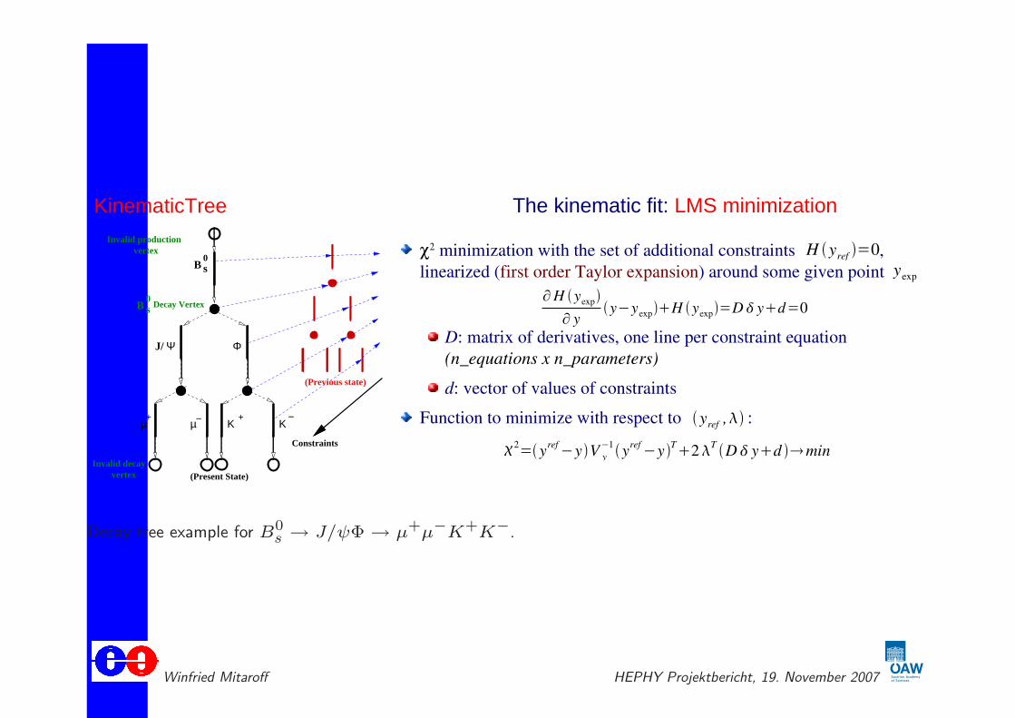
χ2 minimization with the set of additional constraints ,
linearized (first order Taylor expansion) around some given point
D: matrix of derivatives, one line per constraint equation
(n_equations x n_parameters)
d: vector of values of constraints
Function to minimize with respect to :
H �yref ��0
yexp
�H �yexp�
� y�y�yexp��H �yexp��D� y�d�0
�2��y
ref�y�V y
�1�y
ref�y�
T�2
T�D� y�d �min
�yref ,�
Decay tree example for B0s → J/ψΦ → µ+µ−K+K−.
Winfried Mitaroff HEPHY Projektbericht, 19. November 2007
RAVE/VERTIGO – status and outlook
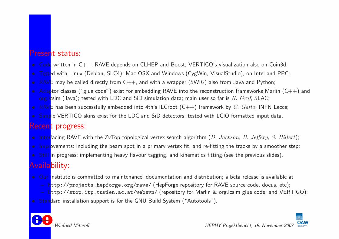
Present status:
• Code written in C++; RAVE depends on CLHEP and Boost, VERTIGO’s visualization also on Coin3d;
• Tested with Linux (Debian, SLC4), Mac OSX and Windows (CygWin, VisualStudio), on Intel and PPC;
• RAVE may be called directly from C++, and with a wrapper (SWIG) also from Java and Python;
• Adaptor classes (“glue code”) exist for embedding RAVE into the reconstruction frameworks Marlin (C++) andorg.lcsim (Java); tested with LDC and SiD simulation data; main user so far is N. Graf, SLAC;
• RAVE has been successfully embedded into 4th’s ILCroot (C++) framework by C. Gatto, INFN Lecce;
• Simple VERTIGO skins exist for the LDC and SiD detectors; tested with LCIO formatted input data.
Recent progress:
• Interfacing RAVE with the ZvTop topological vertex search algorithm (D. Jackson, B. Jeffery, S. Hillert);
• Improvements: including the beam spot in a primary vertex fit, and re-fitting the tracks by a smoother step;
• Still in progress: implementing heavy flavour tagging, and kinematics fitting (see the previous slides).
Availability:
• Our institute is committed to maintenance, documentation and distribution; a beta release is available at
– http://projects.hepforge.org/rave/ (HepForge repository for RAVE source code, docus, etc);– http://stop.itp.tuwien.ac.at/websvn/ (repository for Marlin & org.lcsim glue code, and VERTIGO);
• Standard installation support is for the GNU Build System (“Autotools”).
Winfried Mitaroff HEPHY Projektbericht, 19. November 2007
The “LiC Detector Toy” – main features
• The “LiC Detector Toy” is a simple but powerful program tool for detector design studies. It aims at investigatingtrack resolutions for the purpose of optimizing the layout (geometries and material budgets).
• Detector model corresponds to a collider experiment with a solenoid magnet. Geometry is cylinder symmetricw.r.t. beam axis z, but not necessarily symmetric w.r.t. the z = 0 plane. Surfaces are either cylinders (“barrel”)
or planes (“forward/backward region”). The track model is a helix.
• The latest version supports tracking from the barrel into the forward/backward region, and vice versa (i.e.
re-entry into the barrel). However, this feature is not yet fully tested.
• Simulation takes into account multiple scattering, detector inefficiencies and measurement errors, but no other
degradation. Track reconstruction is performed by a Kalman filter, with the reference surface being the inside ofthe beam tube. Goodness-of-fit tests are standard.
• Supported detectors are Si pixels, Si strips (single- or double-sided with any stereo angle), and a TPC. Detectordescription defined by a simple “input sheet”. An interactive GUI is available as well.
• The program is written in MatLab. A beta release is available on request. For more information, please, consultthe User Guide at
http://wwwhephy.oeaw.ac.at/p3w/ilc/reports/LiC_Det_Toy/Reports/UserGuide.pdf
and the ILC forum athttp://forum.linearcollider.org/ → Fast Simulations → LiC Detector Toy.
Winfried Mitaroff HEPHY Projektbericht, 19. November 2007
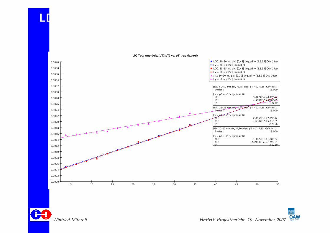
LDC and SiD barrel track resolutions: ∆pT/pT
Winfried Mitaroff HEPHY Projektbericht, 19. November 2007
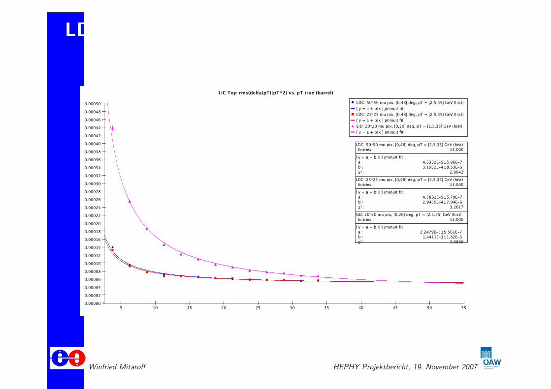
LDC and SiD barrel track resolutions: ∆pT/p2T
Winfried Mitaroff HEPHY Projektbericht, 19. November 2007
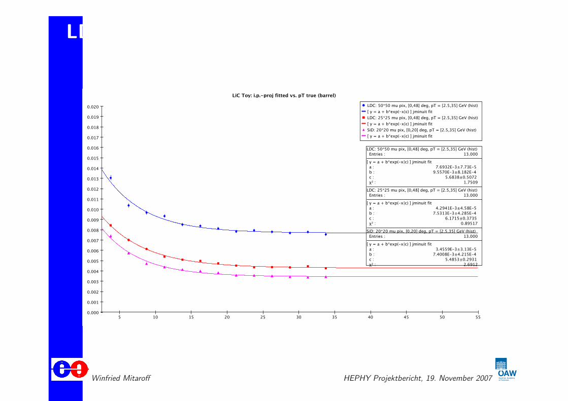
LDC and SiD barrel track resol.: transverse i.p.
Winfried Mitaroff HEPHY Projektbericht, 19. November 2007
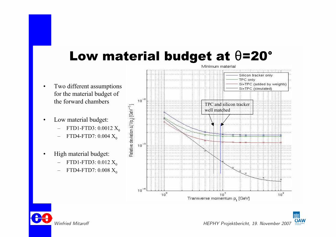
LDC forward track resolution: ∆pT/p2T
Low material budget at =20°
• Two different assumptions
for the material budget of
the forward chambers
• Low material budget:
– FTD1-FTD3: 0.0012 X0
– FTD4-FTD7: 0.004 X0
• High material budget:
– FTD1-FTD3: 0.012 X0
– FTD4-FTD7: 0.008 X0
TPC and silicon tracker
well matched
Winfried Mitaroff HEPHY Projektbericht, 19. November 2007

LDC forward track resolution: ∆pT/p2T
High material budget at =20°• Blue: Silicon tracker only
• Green: TPC only
• Red: Silicon tracker & TPC
– Added by weights of
marginal distributions
– Si tracker and TPC
completely independent
• Black: Simulation of both
– Bump at middle momentum
– Line: (a+b/pt2) fit,
exclusion of bump points
– Circles: badly matching
points
• Magenta: Additional forward
chamber at z = 900mm
– No improvement
TPC and silicon tracker
not well matched
Full Kalman filter
corresponds to average
with correlated full
weight matrix (5x5)
Weighted average
of independent (1/pt)
measurements
Winfried Mitaroff HEPHY Projektbericht, 19. November 2007

6th SiLC Meeting - Torino17th - 19th December 2007
We are looking forward to see you!
INFN Torino - University of Torino
Email: , Diego Gamba Lorenzo Zamprotta © Lorenzo Zamprotta
Home
Welcome
Agenda
Informations
Accommodation
Transport
Registration
List of participants
INFN Web Page
SILC Web Page
19.11.2007 15:28 Uhr6th SILC Meeting - Turin
Page 1 of 1http://www.silc.to.infn.it/

ILC Reference Design Report – parts 2 & 4
Reference Design ReportPhysics at the ILC
August 2007
ILC-REPORT-2007-001
international linear collider
Reference Design ReportDetectors
August 2007
ILC-REPORT-2007-001
international linear collider
All 4 parts can be downloaded from http://www.linearcollider.org/rdr/
Winfried Mitaroff HEPHY Projektbericht, 19. November 2007