Redundante Dr. Rudolf Wieser Regelungssysteme für … · ©ABB Group -10- 16-Apr-08 UNITROL 6080...
35
© ABB Group - 1 - 16-Apr-08 UNITROL ® SYNCHROTACT ® Redundante Regelungssysteme für grosse Synchronmaschinen ABB Schweiz AG Dr. Rudolf Wieser
Transcript of Redundante Dr. Rudolf Wieser Regelungssysteme für … · ©ABB Group -10- 16-Apr-08 UNITROL 6080...
©AB
B G
roup
-1
-16
-Apr
-08
UNITROL®
SYNCHROTACT®Redundante Regelungssysteme für grosse Synchronmaschinen
ABB Schweiz AG
Dr. Rudolf Wieser
©AB
B G
roup
-2
-16
-Apr
-08
Inhalt Redundante Regelungssysteme
Anforderungen und Funktionen
Redundanzlösungen
FunktionseinheitenRegelungselektronik
Stromrichter
Schutz
Ausblick
©AB
B G
roup
-3
-16
-Apr
-08
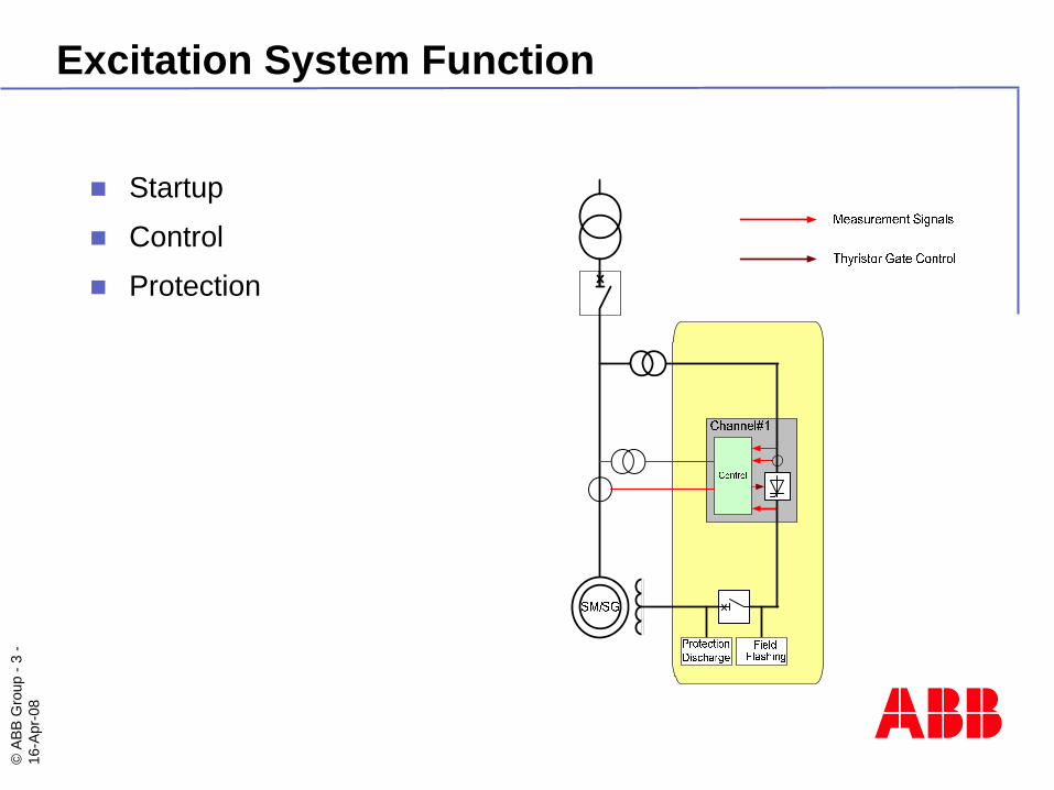
Excitation System Function
Startup
Control
Protection
©AB
B G
roup
-4
-16
-Apr
-08
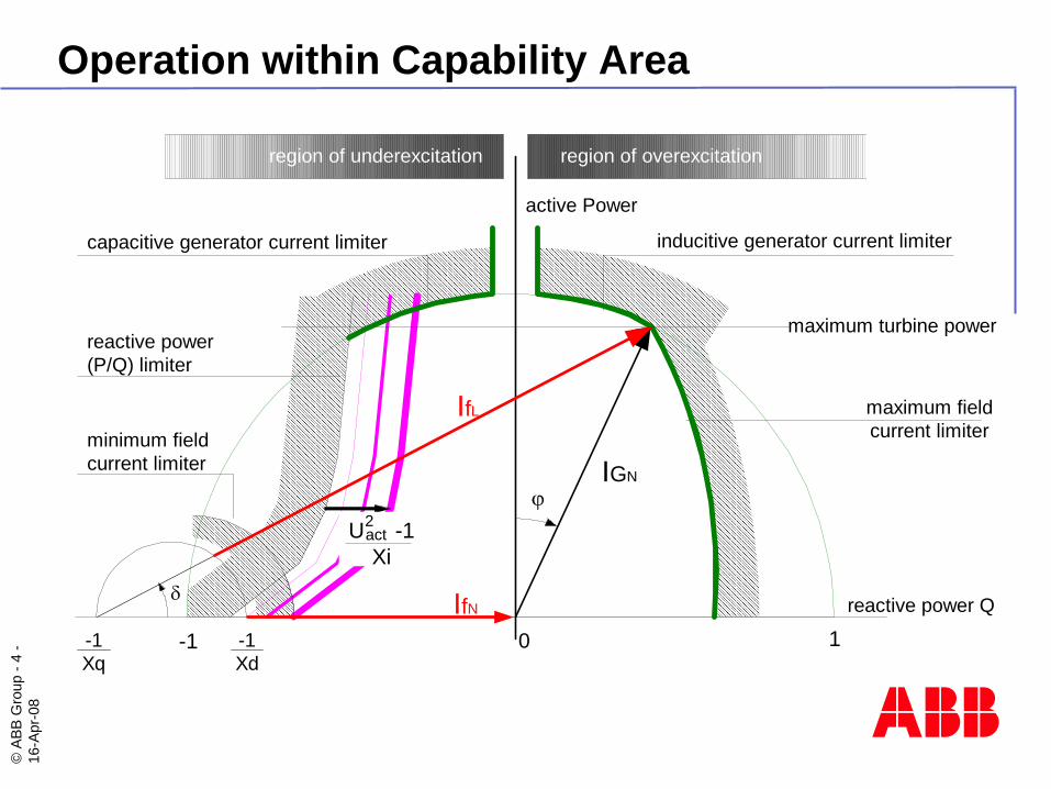
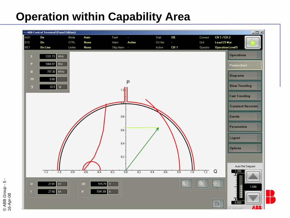
Operation within Capability Area
reactive power Qδ
0-1 1
capacitive generator current limiter inducitive generator current limiter
maximum turbine power
maximum fieldcurrent limiter
region of underexcitation region of overexcitation
active Power
minimum fieldcurrent limiter
reactive power(P/Q) limiter
-1Xq
-1Xd
U -1Xi
act2
IfL
IGNϕ
IfN
©AB
B G
roup
-5
-16
-Apr
-08
Operation within Capability Area
©AB
B G
roup
-6
-16
-Apr
-08
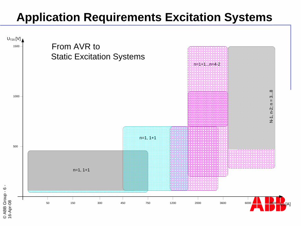
Application Requirements Excitation Systems
IEN [A]
UT20 [V]
500
1000
1500
450 750 3600 1000060002000120030015050
n=1, 1+1
n=1, 1+1
n=1+1...n=4-2
N-1
, n-2
; n =
3...
8
From AVR to Static Excitation Systems
©AB
B G
roup
-7
-16
-Apr
-08
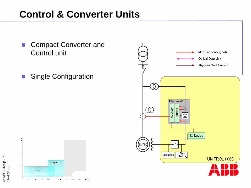
Control & Converter Units
Compact Converter and Control unit
Single Configuration
©AB
B G
roup
-8
-16
-Apr
-08
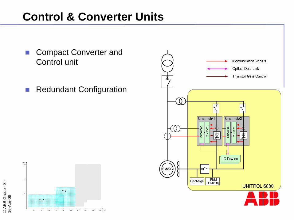
Control & Converter Units
Compact Converter and Control unit
Redundant Configuration
©AB
B G
roup
-9
-16
-Apr
-08
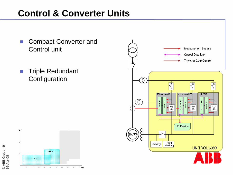
Control & Converter Units
Compact Converter and Control unit
Triple Redundant Configuration
©AB
B G
roup
-10
-16
-Apr
-08
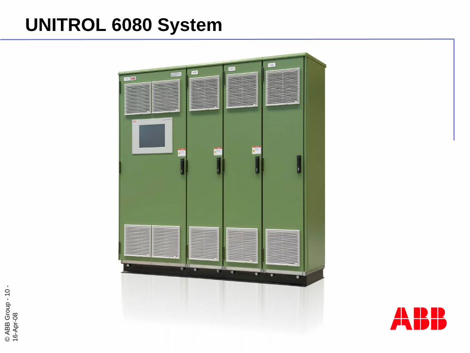
UNITROL 6080 System
©AB
B G
roup
-11
-16
-Apr
-08
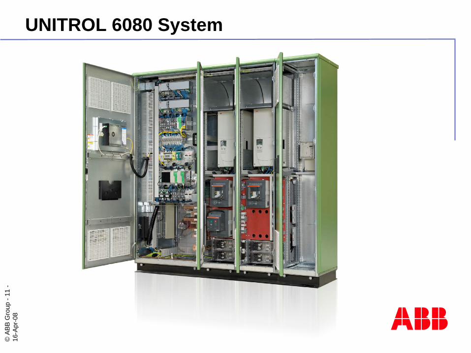
UNITROL 6080 System
©AB
B G
roup
-12
-16
-Apr
-08
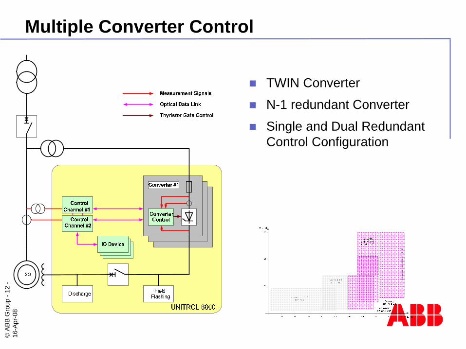
Multiple Converter Control
TWIN Converter
N-1 redundant Converter
Single and Dual Redundant Control Configuration
Con
verte
r UN
L143
6x 4
“ n 2
...8
©AB
B G
roup
-13
-16
-Apr
-08
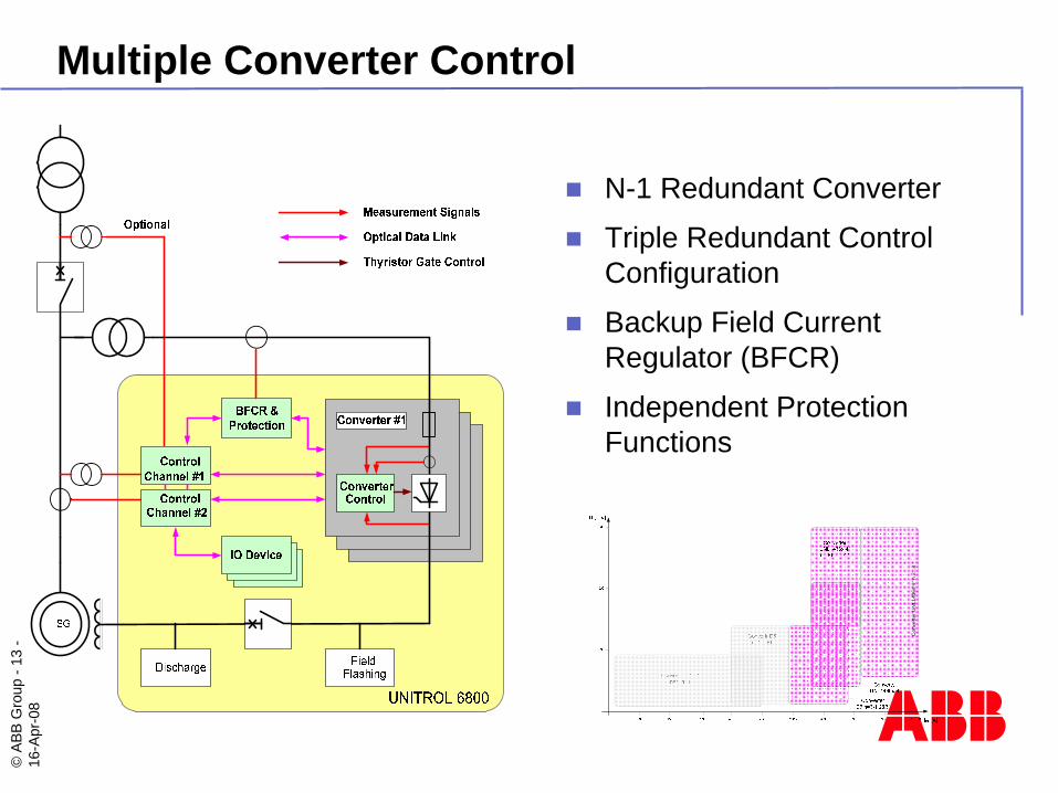
N-1 Redundant Converter
Triple Redundant Control Configuration
Backup Field CurrentRegulator (BFCR)
Independent Protection Functions
Con
verte
r UN
L143
6x 4
“ n 2
...8
Multiple Converter Control
©AB
B G
roup
-14
-16
-Apr
-08
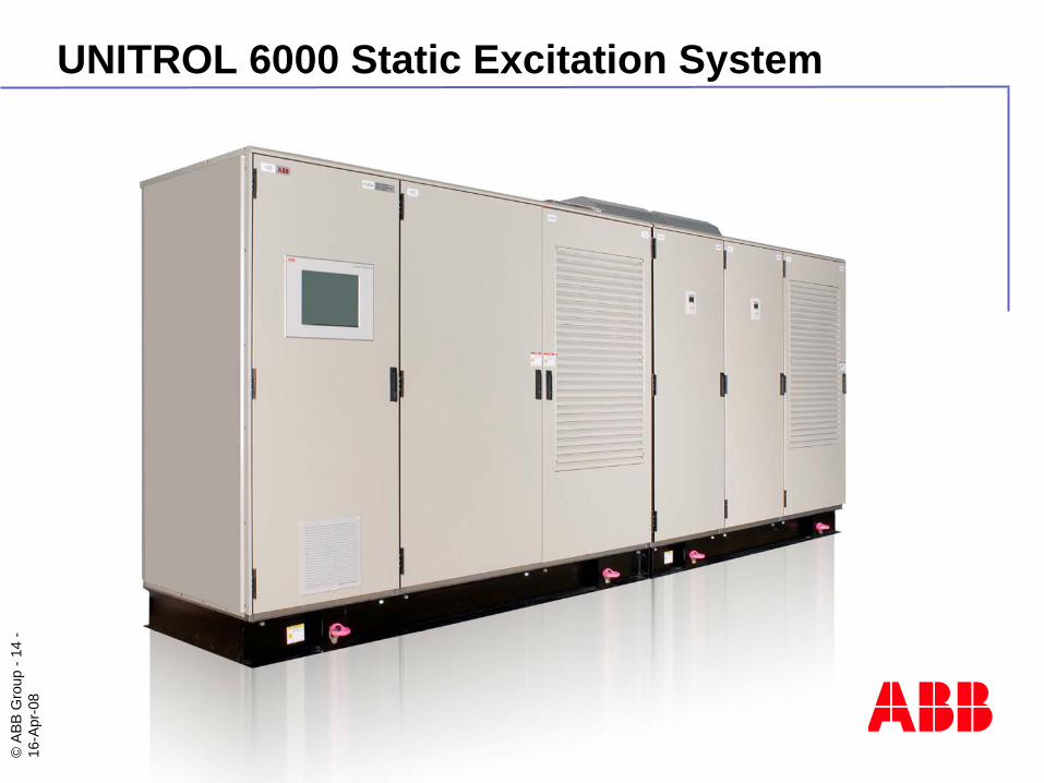
UNITROL 6000 Static Excitation System
©AB
B G
roup
-15
-16
-Apr
-08
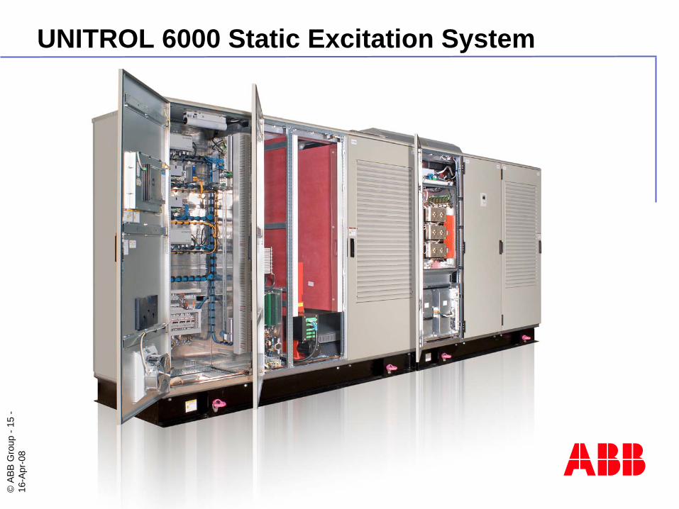
UNITROL 6000 Static Excitation System
©AB
B G
roup
-16
-16
-Apr
-08
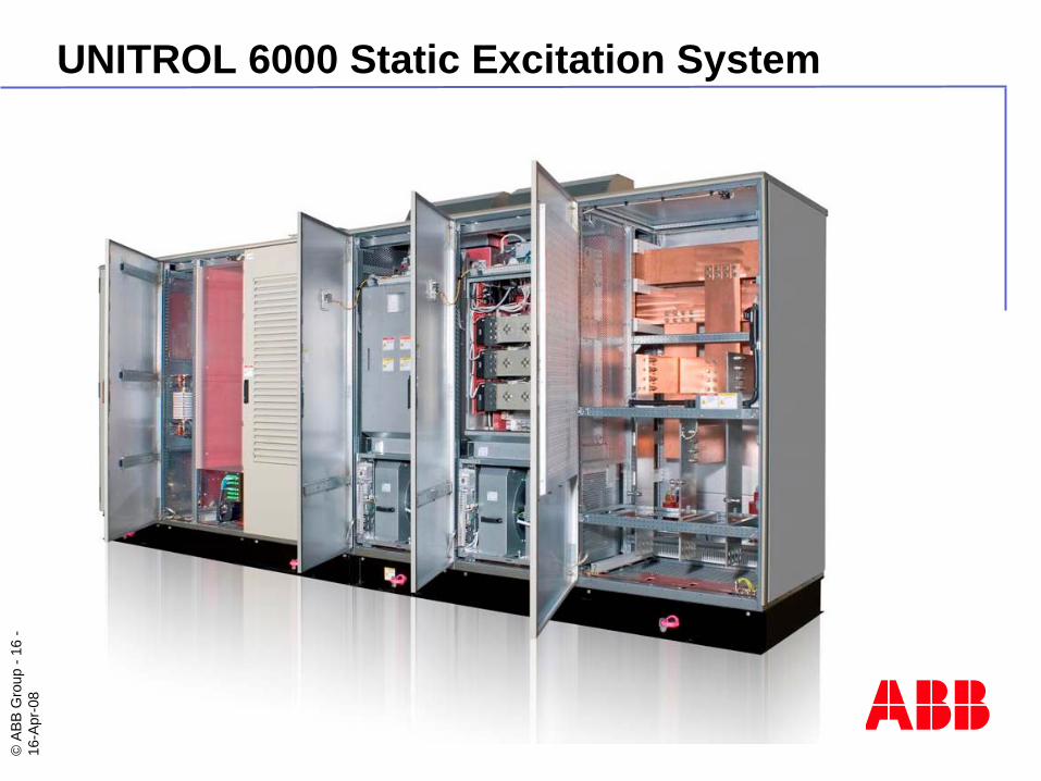
UNITROL 6000 Static Excitation System
©AB
B G
roup
-17
-16
-Apr
-08
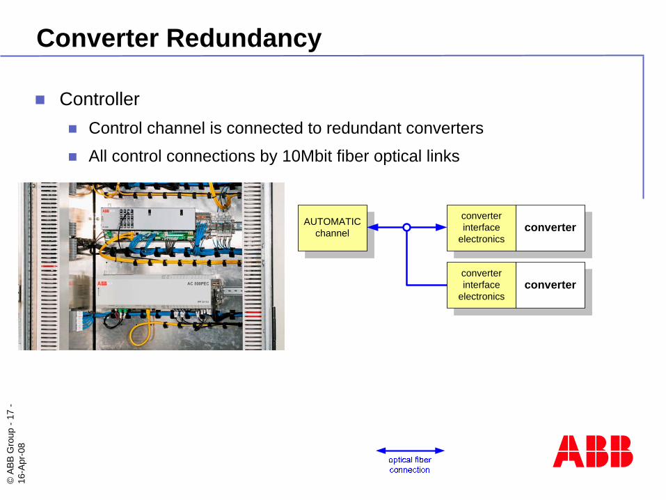
Converter Redundancy
ControllerControl channel is connected to redundant converters
All control connections by 10Mbit fiber optical links
AUTOMATICchannel
converterinterface
electronicsconverter
converterinterface
electronicsconverter
©AB
B G
roup
-18
-16
-Apr
-08
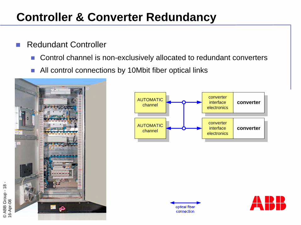
Controller & Converter Redundancy
Redundant ControllerControl channel is non-exclusively allocated to redundant converters
All control connections by 10Mbit fiber optical links
AUTOMATICchannel
converterinterface
electronics
AUTOMATICchannel
converter
converterinterface
electronicsconverter
©AB
B G
roup
-19
-16
-Apr
-08
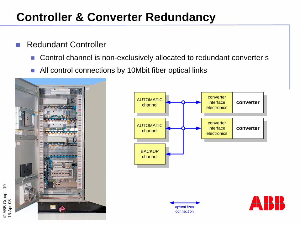
Controller & Converter Redundancy
Redundant ControllerControl channel is non-exclusively allocated to redundant converter s
All control connections by 10Mbit fiber optical links
AUTOMATICchannel
converterinterface
electronics
AUTOMATICchannel
converter
BACKUPchannel
converterinterface
electronicsconverter
©AB
B G
roup
-20
-16
-Apr
-08
AUTOMATICchannel
converterinterface
electronics
AUTOMATICchannel
converter
converterinterface
electronicsconverter
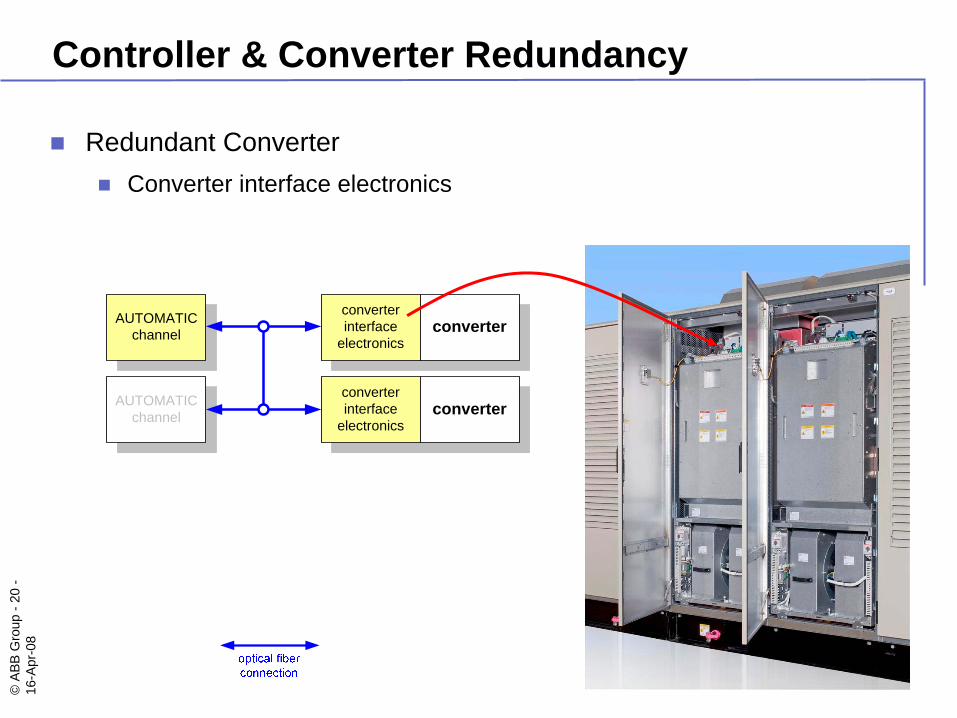
Controller & Converter Redundancy
Redundant ConverterConverter interface electronics
©AB
B G
roup
-21
-16
-Apr
-08
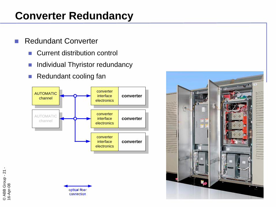
Converter Redundancy
Redundant ConverterCurrent distribution control
Individual Thyristor redundancy
Redundant cooling fan
AUTOMATICchannel
converterinterface
electronics
AUTOMATICchannel
converterinterface
electronics
converter
converterinterface
electronics
converter
converter
©AB
B G
roup
-22
-16
-Apr
-08
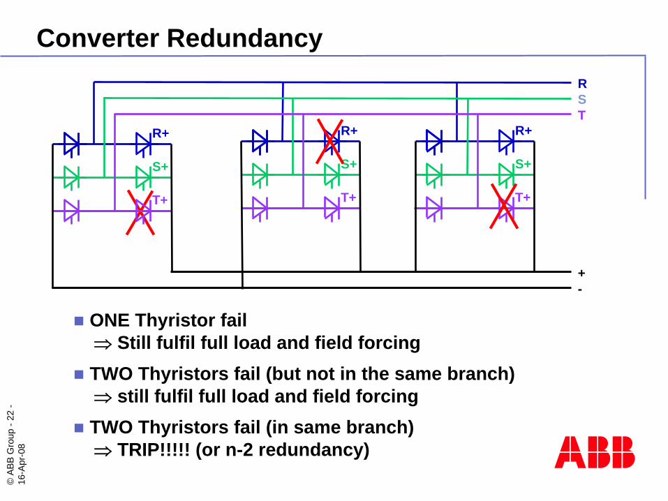
ONE Thyristor fail ⇒ Still fulfil full load and field forcingTWO Thyristors fail (but not in the same branch) ⇒ still fulfil full load and field forcingTWO Thyristors fail (in same branch) ⇒ TRIP!!!!! (or n-2 redundancy)
TR+
S+
T+
S
R+
S+
T+
R
R+
S+
T+
+-
Converter Redundancy
©AB
B G
roup
-23
-16
-Apr
-08
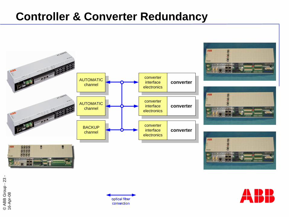
Controller & Converter Redundancy
AUTOMATICchannel
converterinterface
electronics
AUTOMATICchannel
converterinterface
electronics
converter
BACKUPchannel
converterinterface
electronics
converter
converter
©AB
B G
roup
-24
-16
-Apr
-08
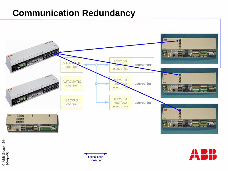
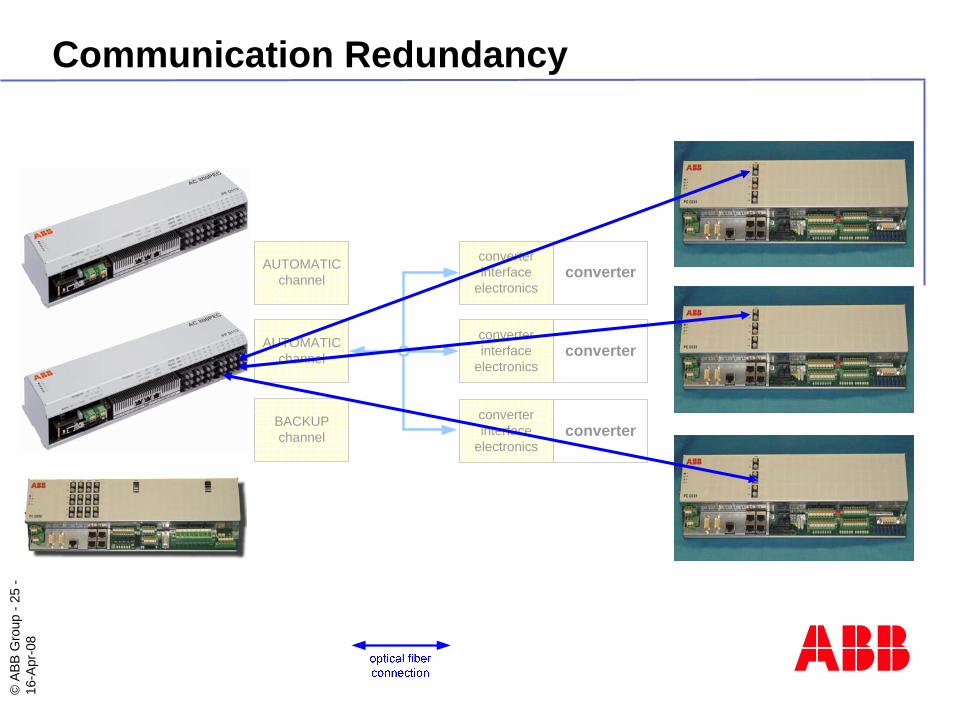
Communication Redundancy
AUTOMATICchannel
converterinterface
electronics
AUTOMATICchannel
converterinterface
electronics
converter
BACKUPchannel
converterinterface
electronics
converter
converter
©AB
B G
roup
-25
-16
-Apr
-08
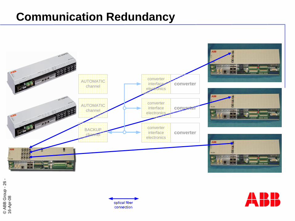
AUTOMATICchannel
converterinterface
electronics
AUTOMATICchannel
converterinterface
electronics
converter
BACKUPchannel
converterinterface
electronics
converter
converter
Communication Redundancy
©AB
B G
roup
-26
-16
-Apr
-08
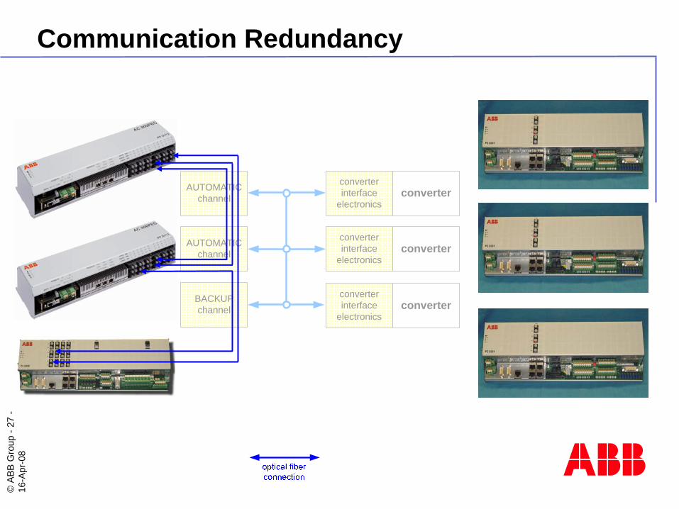
Communication Redundancy
AUTOMATICchannel
converterinterface
electronics
AUTOMATICchannel
converterinterface
electronics
converter
BACKUPchannel
converterinterface
electronics
converter
converter
©AB
B G
roup
-27
-16
-Apr
-08
Communication Redundancy
AUTOMATICchannel
converterinterface
electronics
AUTOMATICchannel
converterinterface
electronics
converter
BACKUPchannel
converterinterface
electronics
converter
converter
©AB
B G
roup
-28
-16
-Apr
-08
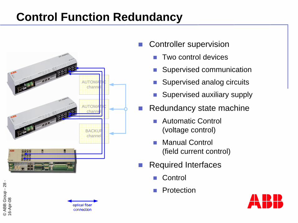
Control Function Redundancy
AUTOMATICchannel
AUTOMATICchannel
BACKUPchannel
Controller supervisionTwo control devices
Supervised communication
Supervised analog circuits
Supervised auxiliary supply
Redundancy state machineAutomatic Control (voltage control)
Manual Control(field current control)
Required InterfacesControl
Protection
©AB
B G
roup
-29
-16
-Apr
-08
1
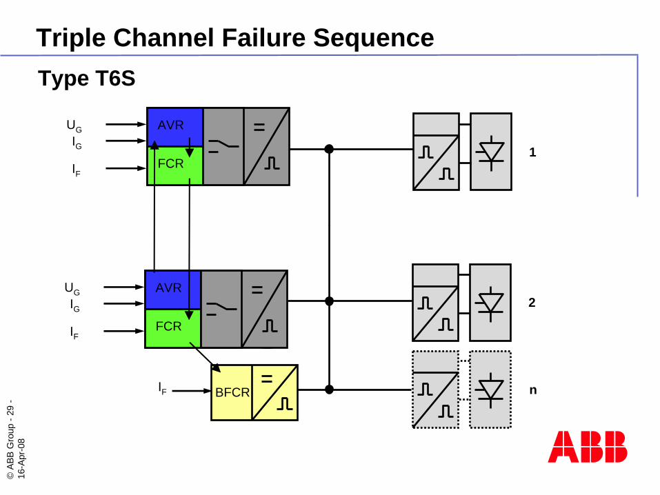
Type T6S
AVR
FCR
UGIG
IF
Triple Channel Failure Sequence
2
n
AVR
FCR
UGIG
IF
IF BFCR
©AB
B G
roup
-30
-16
-Apr
-08
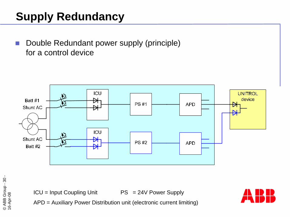
Supply Redundancy
Double Redundant power supply (principle)for a control device
ICU = Input Coupling Unit PS = 24V Power Supply
APD = Auxiliary Power Distribution unit (electronic current limiting)
©AB
B G
roup
-31
-16
-Apr
-08
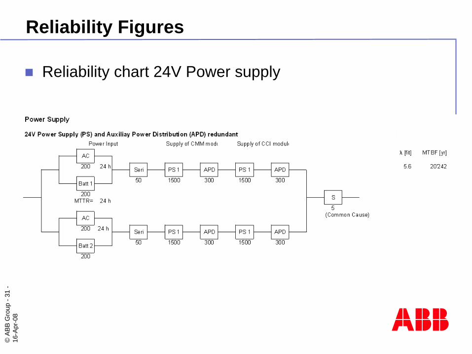
Reliability Figures
Reliability chart 24V Power supply
©AB
B G
roup
-32
-16
-Apr
-08
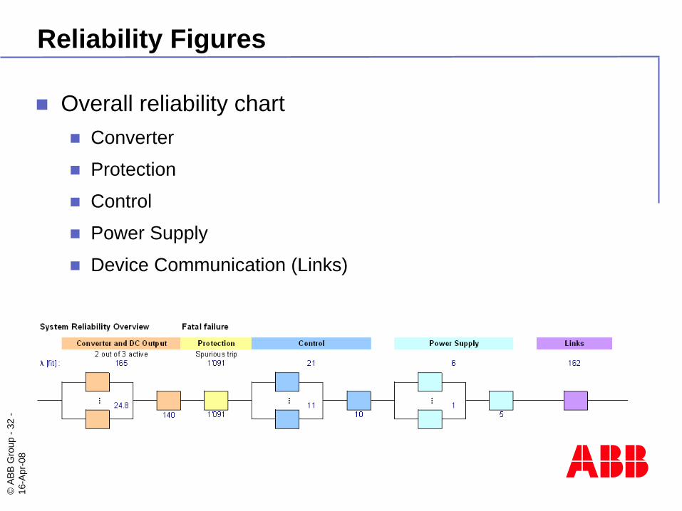
Reliability Figures
Overall reliability chartConverter
Protection
Control
Power Supply
Device Communication (Links)
©AB
B G
roup
-33
-16
-Apr
-08
Outlook
Plant Control Integration IEC61850 for Hydro- and Windpower
Wide Area Control SystemsLocal stabilization with PSS
Wide area monitoring (PMU)
Wide area stabilization
©AB
B G
roup
-34
-16
-Apr
-08
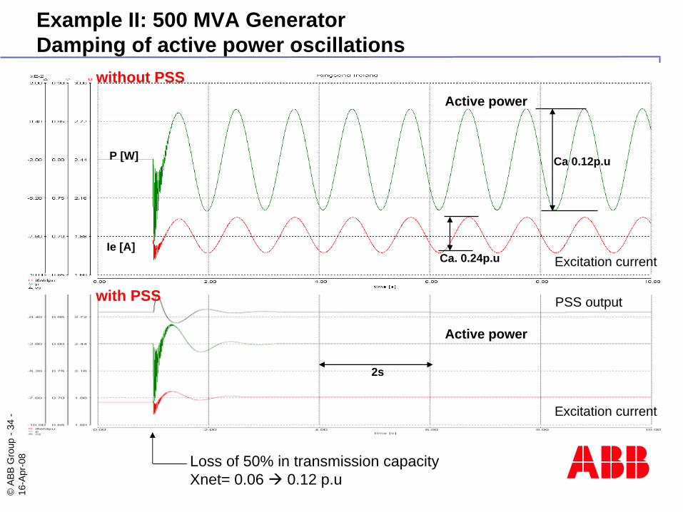
2s
Ca 0.12p.u
Ca. 0.24p.u
P [W]
Ie [A]
without PSS
with PSS
Active power
Active power
Excitation current
Excitation current
Loss of 50% in transmission capacityXnet= 0.06 0.12 p.u
PSS output
Example II: 500 MVA GeneratorDamping of active power oscillations