SELBSTÜBERWACHENDE STEUERUNg THALIA P -...
18
THALIA P D811780A00100_02 02-10-12 ISTRUZIONI DI INSTALLAZIONE INSTALLATION MANUAL INSTRUCTIONS D’INSTALLATION MONTAGEANLEITUNG INSTRUCCIONES DE INSTALACION INSTALLATIEVOORSCHRIFTEN THALIA P Attenzione! Leggere attentamente le “Avvertenze” all’interno! Caution! Read “Warnings” inside carefully! Attention! Veuillez lire attentivement les Avertissements qui se trouvent à l’intérieur! Achtung! Bitte lesen Sie aufmerksam die „Hinweise“ im Inneren! ¡Atención¡ Leer atentamente las “Advertencias” en el interior! Let op! Lees de “Waarschuwingen” aan de binnenkant zorgvuldig! QUADRO COMANDO CONTROL PANEL CENTRALE DE COMMANDE SELBSTÜBERWACHENDE STEUERUNG CUADRO DE MANDOS BEDIENINGSPANEEL 8 027908 426352
Transcript of SELBSTÜBERWACHENDE STEUERUNg THALIA P -...

THA
LIA
PD
8117
80A
0010
0_02
02-
10-1
2
ISTR
UZI
ON
I DI I
NST
ALL
AZI
ON
EIN
STA
LLAT
ION
MA
NU
AL
INST
RUC
TIO
NS
D’IN
STA
LLAT
ION
MO
NTA
gEA
NLE
ITU
Ng
INST
RUCC
ION
ES D
E IN
STA
LACI
ON
INST
ALL
ATIE
VOO
RSCH
RIFT
EN
THA
LIA
P
Attenzione! Leggere attentamente le “Avvertenze” all’interno! Caution! Read “Warnings” inside carefully! Attention! Veuillez lire attentivement les Avertissements qui se trouvent à l’intérieur! Achtung! Bitte lesen Sie aufmerksam die „Hinweise“ im Inneren! ¡Atención¡ Leer atentamente las “Advertencias” en el interior! Let op! Lees de “Waarschuwingen” aan de binnenkant zorgvuldig!
QUADRO COMANDO CONTROL PANEL CENTRALE DE COMMANDE SELBSTÜBERWACHENDE STEUERUNgCUADRO DE MANDOS BEDIENINgSPANEEL
8 027908 4 2 6 3 5 2
INSTALLAZIONE VELOCE-QUICK INSTALLATION-INSTALLATION RAPIDESCHNELLINSTALLATION-INSTALACIÓN RÁPIDA - SNELLE INSTALLATIE
0,75
0,75
3x2,5 mm2 *
3x2,5 mm2 *
5x0,75 mm2
5x0,75 mm2
2x0,75 mm2
A B
C
PREDISPOSIZIONE TUBI, TUBE ARRANGEMENT,PRÉDISPOSITION DES TUYAUX, VORBEREITUNG DER LEITUNGEN,DISPOSICIÓN DE TUBOS, VOORBEREIDING LEIDINGEN.
*Altre tensioni disponibili a richiestaOther voltages available on requestAutres tensions disponibles sur demandeWeitere Spannungen auf Anfrage erhältlichOtras tensiones disponibles a peticiónAndere spanningen op aanvraag beschikbaar
* Vedere speci�ca motoreSee motor speci�cationsConsultez les caractéristiques du moteurSiehe MotordatenVéase especi�caciones motorZie motorspeci�catie
220230V (*)
24V
D
725150 70
24V ~
Collegamento di 1 coppia di fotocellule non veri�cate,Connection of 1 pair of non-tested photocells,Connexion 1 paire photocellules no véri�ées,Anschluss von einem Paar nicht überprüften Fotozellen,Conexión de 1 par fotocélulas no comprobadas,Aansluiting van 1 paar fotocellen anders dan “trusted device”.
21
TX1 21
RX1
45
3
SAFE 1 = 0
220
320
125
40 41 42 43 44 45
50 51 52 60 61 62 70 71 72 73 74 75
COM
SAFE 1
FAULT 1
STOP
SAFE 2
FAULT 2
NC
NC
NC
COM
SAFE 4
FAULT 4
FAULT 3
NC
SAFE 3NC
COM
SAFE 6
FAULT 6
FAULT 5
NC
SAFE 5NC
SicurezzeSafety devicesSécuritésSicherheitsvorrichtungenD
ispositivos de seguridadVeiligheden
76 77 78 79 80 81 82 83 84 8563 64 65
- REF SWE
+ REF SWE
SWC 1 / SW
1 / ENC1A
SWO
1 / SW 2 / ENC1B
SWC2 / ENC2A
SWO
2 / ENC2B
24V -
24V +
24 VSafe+
COM
IC 1
IC 2
NO
NO
COM
IC 3
IC 4
NO
NO
Ingressi �necorsa/encoderEncoder/limit switch inputs
Entrées des �ns de course /encodeurEingänge Anschlag/Encoder
Entradas �nales de carreraEncoder/ingangen
Alim
entazione accessoriAccessories pow
er supplyA
limentation des accessoires
Stromversorgung Zubehör
Alim
entación accesoriosVoeding accessoires
Comandi / Com
mands
Comm
andes /Bedienelemente
Mandos/ Com
mando's
8888
85
6564636261605251504544434241402928272625242322212015141110L N
848382818079787776757473727170
F2 3
.15
AT
F1 2
AT (2
20-2
30V)
F1 4
AT (1
20V)
F3 5
AT
Connettore programmatore palmare,Palmtop programmer connector,Connecteur programmateur de poche,Steckverbinder Palmtop-Programmierer,Conector del programador de bolsillo,Connector programmeerbare palmtop.
Display + tasti programmazioneDisplay + programming keys
Display + ProgrammierungstastenPantalla + botones programaciónDisplay + programmeringstoetsen
Connettore scheda opzionaleOptional board connectorConnecteur carte facultativeSteckverbinder ZusatzkarteConector de la tarjeta opcional Connector optionele kaart
220-230V ~
24V
JP21
*Y
# ANT.
ANTSHIELD Antenna
AntenneAntenaAntenne
L N 10 11
L N M1220-230V ~*
14 15 20 21
+
M2
24V-+ -
AlimentazionePower supplyAlimentation
StromversorgungAlimentación /Voeding
Motore / Motormoteur/Motor
Eindaanslag/Motor AUX
28 29
220230V AUX 3
(MAX 24V 1A)
AUX 2(M
AX 220-230V 5A)
AUX 1 - 220-230V~(M
AX 5A)
22 23 26 2724 25
26
AUX 3 = 0AUX 3 = 2AUX 3 = 3AUX 3 = 4AUX 3 = 5AUX 3 = 6AUX 3 = 7AUX 3 = 8
AUX 3 = 1
27
1
26 27 50 51
24 V~
SCA
12/24V
2 - THALIA P
D81
1780
A00
100_
02

ITALIA
NO
ENG
LISHFRA
NÇA
ISD
EUTSCH
ESPAÑ
OL
NEDERLANDS
40 41 42 43 44 45
+ REF SWE
SWC 1
SWO
1
SWC2
SWO
2
10 11
M1
14 15
+
M2
-+ -
ELI 250 BTtipo otore - type de oteur - otorentyp - otor type - tipo otor: 1
2
E
40 41 42 43 44 45
SW 1
10 11
M1
14 15
M2
+ - + -
PHOBOS BT tipo otore - type de oteur - otorentyp - otor type - tipo otor:
M1
M2M2M1 M1
M2 M2M1
SW 2
3
40 41 42 43 44 45
SW 1
10 11
M1
14 15
+
M2
-+ -
IGEA BT tipo otore - type de oteur - otorentyp - otor type - tipo otor:
M1M2
M2M1
SW 2
1 2 3
SW 1
M1 +
M1-
1 2 3
SW 2
M2 +
M2-
M2M1
1 2 3
SW 1
M1 +
M1-
1 2 3
SW 2
M2 +
M2-
M2M1
M1
M2
M1 M2
M2 M1
M2
M1
inv.direz. ap / open in other direct. inv.sens.ouv / inv richt offnung
inv.direcc.ap./ Omkering openingsrichting:
1 (ext)
inv.direz. ap / open in other direct. inv.sens.ouv / inv richt offnung
inv.direcc.ap./ Omkering openingsrichting:
1 (ext)
inv.direz. ap / open in other direct. inv.sens.ouv / inv richt offnung
inv.direcc.ap./ Omkering openingsrichting:
1 (ext)
inv.direz. ap / open in other direct. inv.sens.ouv / inv richt offnung
inv.direcc.ap./ Omkering openingsrichting:
0 (int)
inv.direz. ap / open in other direct. inv.sens.ouv / inv richt offnung
inv.direcc.ap./ Omkering openingsrichting:
0 (int)
inv.direz. ap / open in other direct. inv.sens.ouv / inv richt offnung
inv.direcc.ap./ Omkering openingsrichting:
0 (int)
THALIA P 3
D81
1780
A00
100_
02

40 41 42 43 44 4510 11
M1
14 15
M2
+ - + -
LUX BTtipo motore - type de moteur - motorentyp - motor type - tipo motor:
SUB BTtipo motore - type de moteur - motorentyp - motor type - tipo motor:
4LUX G BTtipo motore - type de moteur - motorentyp - motor type - tipo motor: 5
6
E
1 2 3 4
M1 +
M1 -
+ REF SWE
SW 1
1 2 3 4
M2 +
M2 -
+ REF SWE
SW 2
reg. fc. - l.sg adj - regl.fc - endsche inst
1 2
M1
M2
M1 M2 M1 M2M2
M1 M1M2
SW 1
+ REF SWE
SW 2
40 41 42 43 44 45
SW 1
SW 2
10 11
M1
14 15
-
M2
+
+ -
M1
M2
M1 M2
M2 M1
M2
M1
*Bianco
*Bianco **Rosso ***NeroWhite Red BlackBlanc Rouge NoirWeiß Rot Nero
Blanco Rojo NegroWit Rood Zwart
**Rosso
**Rosso
*Bianco*Bianco
***Nero
***Nero
**Rosso
***Nero
inv.direz. ap / open in other direct. inv.sens.ouv / inv richt offnung
inv.direcc.ap./ Omkering openingsrichting:
1 (ext)
inv.direz. ap / open in other direct. inv.sens.ouv / inv richt offnung
inv.direcc.ap./ Omkering openingsrichting:
1 (ext)
inv.direz. ap / open in other direct. inv.sens.ouv / inv richt offnung
inv.direcc.ap./ Omkering openingsrichting:
0 (int)
inv.direz. ap / open in other direct. inv.sens.ouv / inv richt offnung
inv.direcc.ap./ Omkering openingsrichting:
0 (int)
4 - THALIA P
D81
1780
A00
100_
02
SIMPLIFIED MENU
language
Dir
ITA
fra
deu
eng
esp
int INT
EXT
: inward opening
EXT: outward opening
type eli
phob
igea
2n. mot.
1
.....
x1
autoset
O 01desidered buttonhidden button releasemem.remotes
end
. . . . . .
o o
MIN 1 - MAX 3AUTO OPEN AUTO CLOSE
Exit Menù
Con�rm/Switchon display
Scroll up
Scroll down
: motor 1 opening limit switch adjustment
: motor 2 opening limit switch adjustment
: motor 2 closing limit switch adjustment
: motor 1 closing limit switch adjustment
ar: automatic operation, residential
sr: semiautomatic operation, residential
ac: automatic operation, commercial
Sc: semiautomatic operation, commercial
Ind : dead man operation
opm1
opm2
clm2
clm1
ersu
endo
o
2 1
2 1
2 1
2 1
-
-
LUX BT / LUX G BT ELI BT / PHOBOS BT / IGEA BT / SUB BT
ARpreset
sr
ac
sc
ind
l.sw adj
THALIA P 7
D81
1780
A00
100_
02

PRESET DEFAULT ar sr ac sc ind
PARAMETERSMotor 2 opening delay time [s] 3 3 3 3 3 3Motor 1 closing delay time [s] 3 3 3 3 3 3
Automatic closing time [s] 10 10 10 10 10 10Time-to-clear traffic light zone [s] 40 40 40 40 40 40
Slow-down distance during opening [%] 10 10 10 10 10 10Slow-down distance during closing [%] 10 10 10 10 10 10
Deceleration distance [%] 15 15 15 15 15 15Leaf force during opening [%] 50 50 50 50 50 50Leaf force during closing [%] 50 50 50 50 50 50
Opening speed [%} 99 99 99 99 99 99Closing speed [%] 99 99 99 99 99 99
Slow-down speed [%] 25 25 25 25 25 25LOGIC
Motor type 0 / / / / /Automatic Closing Time 0 1 0 1 0 0
Fast closing 0 0 0 0 0 0Step-by-step movement 0 1 0 1 0 0
Pre-alarm 0 0 0 1 1 0Deadman 0 0 0 0 0 1
Block pulses during opening 0 0 0 1 1 0Block pulses during TCA 0 0 0 0 0 0
Block pulses during closing 0 0 0 0 0 0Hammer during opening 0 0 0 0 0 0Hammer during closing 0 0 0 0 0 0
Stop maintenance 0 0 0 0 0 0Closing limit switch pressure 0 0 0 0 0 0
ICE feature 0 0 0 0 0 01 motor active 0 / / / / /
Open in other direction 0 / / / / /SAFE 1 0 / / / / /SAFE 2 6 / / / / /SAFE 3 2 / / / / /SAFE 4 4 / / / / /SAFE 5 0 / / / / /SAFE 6 6 / / / / /
IC 1 0 / / / / /IC 2 4 / / / / /IC 3 2 / / / / /IC 4 3 / / / / /
AUX 1 3 / / / / /AUX 2 1 / / / / /AUX 3 0 / / / / /
Type of lock. 0 / / / / /Fixed code 0 0 0 0 0 0
Transmitter programming 1 1 1 1 1 0Serial mode 0 0 0 0 0 0
Address 0 0 0 0 0 0EXPI1 1 / / / / /EXPI2 0 / / / / /
EXPO1 9 / / / / /EXPO2 9 / / / / /
Traffic light pre-flashing 0 0 0 0 0 0Steadily lit red light 0 0 0 0 0 0
8 - THALIA P
D81
1780
A00
100_
02

F76 77 78 79 80
SAFE 3
SAFE 4
FAULT 3
FAULT 4
NC
NC
COM
NC
NC
81 82 83 84 85
SAFE 5
SAFE 6
FAULT 5
FAULT 6
NC
NC
COM
NC
NC
12
12345
51TX1 RX1
Bar 11234561
212345
5250 TX1 RX1
12
12345
TX1 RX1
12
12345
TX2 RX2
Bar 112345
Bar 212345
Bar 1123456
6
6
12
12345
TX1 RX1
Bar 11234561
212345
TX1 RX1
12
12345
TX1 RX1
12
12345
TX2 RX2
Bar 112345
Bar 212345
Bar 1123456
6
6
SAFE
1 =
0,2,
4
SAFE
1 =
6
SAFE
1 =
8
1 PHOT / 1 PHOT OP / 1 PHOT CL
1 PHOT / 1 PHOT OP / 1 PHOT CL
2 PHOT / 2 PHOT OP / 2 PHOT CL
BAR 8K2
1 BAR
1 BAR
2 BAR
50
5250
5250
5150
5150
5150
5150
70
72
70
7273
70
70
72
73
51
5150
5150
5150
52
52
52
72
70
72
7073
7270
5150
7073
7072 8,2Kohm 5%
SAFETY EDGE SAFETY EDGE7074 8,2Kohm 5%
SAFETY EDGE SAFETY EDGE
12
12345
51TX1 RX1
Bar 11234561
212345
5250 TX1 RX1
12
12345
TX1 RX1
12
12345
TX2 RX2
Bar 112345
Bar 212345
Bar 1123456
6
6
12
12345
TX1 RX1
Bar 11234561
212345
TX1 RX1
12
12345
TX1 RX1
12
12345
TX2 RX2
Bar 112345
Bar 212345
Bar 1123456
6
6
SAFE
2 =
0,2,
4
SAFE
2 =
6
SAFE
1 =
1,3,
5
SAFE
1 =
7
SAFE
2 =
1,3,
5
SAFE
2 =
7
SAFE
2 =
8
1 PHOT / 1 PHOT OP / 1 PHOT CL
1 PHOT / 1 PHOT OP / 1 PHOT CL
2 PHOT / 2 PHOT OP / 2 PHOT CL
BAR 8K2
1 BAR
1 BAR
2 BAR
50
5250
5250
5150
5150
5150
5150
70
74
70
7475
70
70
74
75
51
5150
5150
5150
52
52
52
74
70
74
7075
7470
5150
7075
7250 70 71 73 74 75
24V -
24V +
24 VSafe+
COM
SAFE 1
SAFE 2
STOP
FAULT 1
FAULT 2
NC NC
NC
50 70 71 73 74 75
24V -
24V +
24 VSafe+
COM
SAFE 1
SAFE 2
STOP
FAULT 1
FAULT 2
NC NC
NC
12
12345
51TX1 RX1
Bar 11234561
212345
5250 TX1 RX1
12
12345
TX1 RX1
12
12345
TX2 RX2
Bar 112345
Bar 212345
Bar 1123456
6
6
12
12345
TX1 RX1
Bar 11234561
212345
TX1 RX1
12
12345
TX1 RX1
12
12345
TX2 RX2
Bar 112345
Bar 212345
Bar 1123456
6
6
SAFE
3 =
0,2,
4
SAFE
3 =
6
1 PHOT / 1 PHOT OP / 1 PHOT CL
1 PHOT / 1 PHOT OP / 1 PHOT CL
2 PHOT / 2 PHOT OP / 2 PHOT CL
1 BAR
1 BAR
2 BAR
50
5250
5250
5150
5150
5150
5150
76
77
76
7778
76
76
77
78
51
5150
5150
5150
52
52
52
77
76
77
7678
7776
5150
7678
12
12345
51TX1 RX1
Bar 11234561
212345
5250 TX1 RX1
12
12345
TX1 RX1
12
12345
TX2 RX2
Bar 112345
Bar 212345
Bar 1123456
6
6
12
12345
TX1 RX1
Bar 11234561
212345
TX1 RX1
12
12345
TX1 RX1
12
12345
TX2 RX2
Bar 112345
Bar 212345
Bar 1123456
6
6
SAFE
4 =
0,2,
4
SAFE
4 =
6
SAFE
3 =
1,3,
5
SAFE
3 =
7
SAFE
4 =
1,3,
5
SAFE
4 =
7
1 PHOT / 1 PHOT OP / 1 PHOT CL
1 PHOT / 1 PHOT OP / 1 PHOT CL
2 PHOT / 2 PHOT OP / 2 PHOT CL
1 BAR
1 BAR
2 BAR
50
5250
5250
5150
5150
5150
5150
76
79
76
7980
76
76
79
80
51
5150
5150
5150
52
52
52
79
76
79
7680
7976
5150
7680
51 52
SAFE 6SAFE 5SAFE 5SAFE 5
SAFE2
12
12345
51TX1 RX1
Bar 11234561
212345
5250 TX1 RX1
12
12345
TX1 RX1
12
12345
TX2 RX2
Bar 112345
Bar 212345
Bar 1123456
6
6
12
12345
TX1 RX1
Bar 11234561
212345
TX1 RX1
12
12345
TX1 RX1
12
12345
TX2 RX2
Bar 112345
Bar 212345
Bar 1123456
6
6
SAFE
5 =
0,2,
4
SAFE
5 =
6
1 PHOT / 1 PHOT OP / 1 PHOT CL
1 PHOT / 1 PHOT OP / 1 PHOT CL
2 PHOT / 2 PHOT OP / 2 PHOT CL
1 BAR
1 BAR
2 BAR
50
5250
5250
5150
5150
5150
5150
81
82
81
8283
81
81
82
83
51
5150
5150
5150
52
52
52
82
81
82
8183
8281
5150
8183
12
12345
51TX1 RX1
Bar 11234561
212345
5250 TX1 RX1
12
12345
TX1 RX1
12
12345
TX2 RX2
Bar 112345
Bar 212345
Bar 1123456
6
6
12
12345
TX1 RX1
Bar 11234561
212345
TX1 RX1
12
12345
TX1 RX1
12
12345
TX2 RX2
Bar 112345
Bar 212345
Bar 1123456
6
6
SAFE
6 =
0,2,
4
SAFE
6 =
6
SAFE
5 =
1,3,
5
SAFE
5 =
7
SAFE
6 =
1,3,
5
SAFE
6 =
7
1 PHOT / 1 PHOT OP / 1 PHOT CL
1 PHOT / 1 PHOT OP / 1 PHOT CL
2 PHOT / 2 PHOT OP / 2 PHOT CL
1 BAR
1 BAR
2 BAR
50
5250
5250
5150
5150
5150
5150
81
84
81
8485
81
81
84
85
51
5150
5150
5150
52
52
52
84
81
84
8185
8481
5150
8185
SAFE 3
1 3
2 5
5
1 3
2 4
5
1 3
2 4
1 3
2 4
1 3
2 4
1 3
4
SAFE 5
TEST
OFF
TEST
ON
TEST
OFF
TEST
ON
TEST
OFF
TEST
ON
TEST
OFF
TEST
ON
TEST
OFF
TEST
ON
TEST
OFF
TEST
ON
2
SAFE 4
SAFE 1 SAFE 2
THALIA P 17
D81
1780
A00
100_
02

G
H
A
B
C
DOPEN
OPEN
SCHEDA DI ESPANSIONEEXPANSION BOARDCARTE D’EXPANSIONERWEITERUNGSKARTETARJETA DE EXPANSIÓNUITBREIDINGSKAART
Programmeerbare Universele Palmtop
UNIDA
(versione x.40 e successive)(x.40 and later versions)(version x.40 et suivantes)(Version x.40 und nachfolgende)(versión x.40 y sucesivas )(versie x.40 en hoger)
18 - THALIA P
D81
1780
A00
100_
02
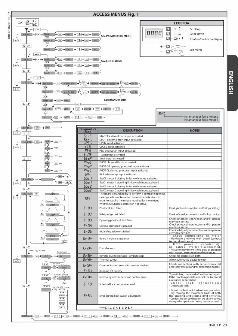
35.40 Instantaneous force motor 2 Instantaneous force motor 1
Diagnostics code DESCRIPTION NOTES
STRE START E external start input activated STRI START I internal start input activated OPEN OPEN input activated CLS CLOSE input activated
PED PED pedestrian input activated
TIME TIMER input activated STOP STOP input activated PHOT PHOT photocell input activated
PHOP PHOT OP opening photocell input activated
PHCL PHOT CL closing photocell input activated
BAR BAR safety edge input activated
SWC1 SWC1 motor 1 closing limit switch input activated
SWO1 SWO1 motor 1 opening limit switch input activated
SWC2 SWC2 motor 2 closing limit switch input activated
SWO2 SWO2 motor 2 opening limit switch input activated
SET
The board is standing by to perform a complete opening-closing cycle uninterrupted by intermediate stops in order to acquire the torque required for movement. WARNINg! Obstacle detection not active
ER01 Photocell test failed Check photocell connection and/or logic settings
ER02 Safety edge test failed Check safety edge connection and/or logic settings
ER03 Opening photocell test failed Check photocell connection and/or param-eter/logic setting
ER04 Closing photocell test failed Check photocell connection and/or param-eter/logic setting
er06 8k2 safety edge test failed Check safety edge connection and/or param-eter/logic settings
ER1x* Board hardware test error- C h e c k c o n n e c t i o n s t o m o t o r - Hardware problems with board (contact technical assistance)
ER2x* Encoder error- M o t o r p o w e r o r e n c o d e r s i g -n a l c a b l e s i n v e r t e d / d i s c o n n e c t e d . - Actuator movement is too slow or stopped with respect to programmed operation.
ER3x* Reverse due to obstacle - Amperostop Check for obstacles in path
ER4x* Thermal cutout Allow automated device to cool
ER5x* Communication error with remote devices Check connection with serial-connected accessory devices and/or expansion boards
ER61 Running off battery --
ER7x* Internal system supervision control error.Try switching the board off and back on again. If the problem persists, contact the technical assistance department.
ERF9 Solenoid lock output overload - C h e c k l o c k c o n n e c t i o n s - Unsuitable lock
Ersw Error during limit switch adjustment
- Repeat the limit switch adjustment procedure. - Try moving the maximum limits of both the opening and closing limit switches. - Caution: the last centimetre of the piston’s stroke, during either opening or closing, cannot be used.
*X= 0, 1, .., 9, A, B, C, D, E, F
ACCESS MENUS Fig. 1
stat
password
x 2
- +
- +
OKvers bft . . .
+/-
OK 0000
+/-
+/-
+/-
n. cycles
OK
OK 01.33
0--- 10-- 150- 1520 prg
00
- +
err
autoset
l.sw adj
02.01
........
30.15
+/-
opm1
opm2
clm2
clm1
ersu
o
2 1
2 1
2 1
2 1
-
-
Exit Menù
Con�rm/Switch on display
Scroll up
Scroll downSee PARAMETERS MENU
See LOGIC MENU
See RADIO MENU
add. start hidden butt
hidden butt
release
release
desired button
desired buttonAdd. 2ch
erase 64
language
n. remotes
List of last 30 errors
Control unitsoftware version
No totalmanoeuvres(in hundreds)
No radio controldevices memorised
ENG
LISH
THALIA P 29
D81
1780
A00
100_
02

INSTALLER WARNINGS
Anything that is not explicitly provided for in the installation ma-nual is not allowed. The operator’s proper operation can only be guaranteed if the information given is complied with. The Firm shall not be answerable for damage caused by failure to comply with the instructions featured herein.While we will not alter the product’s essential features, the Firm re-serves the right, at any time, to make those changes deemed oppor-tune to improve the product from a technical, design or commercial point of view, and will not be required to update this publication accordingly.
WARNING! Important safety instructions. Carefully read and comply with all the warnings and instructions that come with the product as incorrect installation can cause injury to people and animals and damage to property. The warnings and instructions give important information regarding safety, installation, use and maintenance. Keep hold of instructions so that you can attach them to the technical file and keep them handy for future reference.
GENERAL SAFETYThis product has been designed and built solely for the purpose indicated herein. Uses other than those indicated herein might cause damage to the product and create a hazard.- The units making up the machine and its installation must meet the requirements of the following European Directives, where applicable: 2004/108/EC, 2006/95/EC, 2006/42/EC, 89/106/EC, 99/05/EC and later amendments. For all countries outside the EEC, it is advisable to comply with the standards mentioned, in ad-dition to any national standards in force, to achieve a good level of safety.
- The Manufacturer of this product (hereinafter referred to as the “Firm”) disclaims all responsibility resulting from improper use or any use other than that for which the product has been designed, as indicated herein, as well as for failure to apply Good Practice in the construction of entry systems (doors, gates, etc.) and for deformation that could occur during use.
- Before installing the product, make all structural changes required to produce safety gaps and to provide protection from or isolate all crushing, shearing and dragging hazard areas and danger zones in general in accordance with the provisions of standards EN 12604 and 12453 or any local installation standards. Check that the existing structure meets the necessary strength and stability requirements.
- Before commencing installation, check the product for damage.- The Firm is not responsible for failure to apply Good Practice in the construction and maintenance of the doors, gates, etc. to be motorized, or for deformation that might occur during use.
- Make sure the stated temperature range is compatible with the site in which the automated system is due to be installed.
- Do not install this product in an explosive atmosphere: the presence of flammable fumes or gas constitutes a serious safety hazard.
- Disconnect the electricity supply before performing any work on the system. Also disconnect buffer batteries, if any are connected.
- Before connecting the power supply, make sure the product’s ratings match the mains ratings and that a suitable residual current circuit breaker and overcurrent protection device have been installed upline from the electrical system. Have the automated system’s mains power supply fitted with a switch or omnipolar thermal-magnetic circuit breaker with a contact separation that meets code requirements.
- Make sure that upline from the mains power supply there is a residual current circuit breaker that trips at no more than 0.03A as well as any other equipment required by code.
- Make sure the earth system has been installed correctly: earth all the metal parts belonging to the entry system (doors, gates, etc.) and all parts of the system featuring an earth terminal.
- Installation must be carried out using safety devices and controls that meet standards EN 12978 and EN 12453.
- Impact forces can be reduced by using deformable edges.- In the event impact forces exceed the values laid down by the relevant standards, apply electro-sensitive or pressure-sensitive devices.
- Apply all safety devices (photocells, safety edges, etc.) required to keep the area free of impact, crushing, dragging and shearing hazards. Bear in mind the standards and directives in force, Good Practice criteria, intended use, the instal-lation environment, the operating logic of the system and forces generated by the automated system.
- Apply all signs required by current code to identify hazardous areas (residual risks). All installations must be visibly identified in compliance with the provisions of standard EN 13241-1.
- Once installation is complete, apply a nameplate featuring the door/gate’s data.- This product cannot be installed on leaves incorporating doors (unless the motor can be activated only when the door is closed).
- If the automated system is installed at a height of less than 2.5 m or is accessible, the electrical and mechanical parts must be suitably protected.
- Install any fixed controls in a position where they will not cause a hazard, away from moving parts. More specifically, hold-to-run controls must be positioned within direct sight of the part being controlled and, unless they are key operated, must be installed at a height of at least 1.5 m and in a place where they cannot be reached by the public.
- Apply at least one warning light (flashing light) in a visible position, and also attach a Warning sign to the structure.
- Attach a label near the operating device, in a permanent fashion, with informa-tion on how to operate the automated system’s manual release.
- Make sure that, during operation, mechanical risks are avoided or relevant protective measures taken and, more specifically, that nothing can be banged, crushed, caught or cut between the part being operated and surrounding parts.
- Once installation is complete, make sure the motor automation settings are correct and that the safety and release systems are working properly.
- Only use original spare parts for any maintenance or repair work. The Firm dis-claims all responsibility for the correct operation and safety of the automated system if parts from other manufacturers are used.
- Do not make any modifications to the automated system’s components unless explicitly authorized by the Firm.
- Instruct the system’s user on what residual risks may be encountered, on the control systems that have been applied and on how to open the system manu-ally in an emergency. give the user guide to the end user.
- Dispose of packaging materials (plastic, cardboard, polystyrene, etc.) in accord-ance with the provisions of the laws in force. Keep nylon bags and polystyrene out of reach of children.
WIRINGWARNING! For connection to the mains power supply, use: a multicore cable with a cross-sectional area of at least 5x1.5mm2 or 4x1.5mm2 when dealing with three-phase power supplies or 3x1.5mm2 for single-phase supplies (by way of example, type H05 VV-F cable can be used with a cross-sectional area of 4x1.5mm2). To con-nect auxiliary equipment, use wires with a cross-sectional area of at least 0.5 mm2.- Only use pushbuttons with a capacity of 10A-250V or more.- Wires must be secured with additional fastening near the terminals (for example,
using cable clamps) in order to keep live parts well separated from safety extra low voltage parts.
- During installation, the power cable must be stripped to allow the earth wire to be connected to the relevant terminal, while leaving the live wires as short as possible. The earth wire must be the last to be pulled taut in the event the cable’s fastening device comes loose.
WARNING! safety extra low voltage wires must be kept physically separate from low voltage wires.Only qualified personnel (professional installer) should be allowed to access live parts.
CHECKING THE AUTOMATED SYSTEM AND MAINTENANCEBefore the automated system is finally put into operation, and during maintenance work, perform the following checks meticulously:- Make sure all components are fastened securely.- Check starting and stopping operations in the case of manual control.- Check the logic for normal or personalized operation.- For sliding gates only: check that the rack and pinion mesh correctly with 2 mm of play along the full length of the rack; keep the track the gate slides on clean and free of debris at all times.
- For sliding gates and doors only: make sure the gate’s running track is straight and horizontal and that the wheels are strong enough to take the weight of the gate.
- For cantilever sliding gates only: make sure there is no dipping or swinging during operation.
- For swing gates only: make sure the leaves’ axis of rotation is perfectly vertical.- Check that all safety devices (photocells, safety edges, etc.) are working properly and that the anti-crush safety device is set correctly, making sure that the force of impact measured at the points provided for by standard EN 12445 is lower than the value laid down by standard EN 12453.
- Impact forces can be reduced by using deformable edges.- Make sure that the emergency operation works, where this feature is provided.- Check opening and closing operations with the control devices applied.- Check that electrical connections and cabling are intact, making extra sure that insulating sheaths and cable glands are undamaged.
- While performing maintenance, clean the photocells’ optics.- When the automated system is out of service for any length of time, activate the emergency release (see “EMERGENCY OPERATION” section) so that the operated part is made idle, thus allowing the gate to be opened and closed manually.
- If the power cord is damaged, it must be replaced by the manufacturer or their technical assistance department or other such qualified person to avoid any risk .
- If “D” type devices are installed (as defined by EN12453), connect in unverified mode, foresee mandatory maintenance at least every six months
WARNING! Remember that the drive is designed to make the gate/door easier to use and will not solve problems as a result of defective or poorly performed installation or lack of maintenance
SCRAPPINGMaterials must be disposed of in accordance with the regulations in force. There are no particular hazards or risks involved in scrapping the automated system. For the purpose of recycling, it is best to separate dismantled parts into like materials (electrical parts - copper - aluminium - plastic - etc.).
DISMANTLINGIf the automated system is being dismantled in order to be reassembled at another site, you are required to:- Cut off the power and disconnect the whole electrical system.- Remove the actuator from the base it is mounted on.- Remove all the installation’s components.- See to the replacement of any components that cannot be removed or happen to be damaged.
AVVERTENZE PER L’INSTALLATORE D811766_0630 - THALIA P
D81
1780
A00
100_
02

INSTALLATION MANUAL2) GENERAL INFORMATIONThe THALIA P control panel comes with standard factory settings. Any change must be made using the programmer with built-in display or universal handheld programmer. The Control unit completely supports the EELINK protocol.Its main features are: - Control of 1 or 2 24V BT motors Note: 2 motors of the same type must be used.- Electronic torque control with obstacle detection- Limit switch control inputs based on motor selected- Separate inputs for safety devices- Built-in radio receiver rolling code with transmitter cloning.The board has a terminal strip of the removable kind to make maintenance or replacement easier. It comes with a series of prewired jumpers to make the installer’s job on site easier.The jumpers concern terminals: 70-71, 70-72, 70-74, 76-77, 76-79, 81-82, 81-84. If the above-mentioned terminals are being used, remove the rel-evant jumpers.
TESTINGThe THALIA P panel controls (checks) the start relays and safety devices (pho-tocells) before performing each opening and closing cycle. If there is a malfunction, make sure that the connected devices are working properly and check the wiring.
3) TECHNICAL SPECIFICATIONS
Power supply 220-230V 50/60Hz(*)Low voltage/mains insulation > 2MOhm 500V Operating temperature range -10 / +55°CThermal overload protection SoftwareDielectric rigidity mains/LV 3750V~ for 1 minuteMotor output current max. 7.5A+7.5AMotor relay switching current 10A
Maximum motor power 180W + 180W (24V )
Accessories power supply 24V~ (demand max. 1A)24V~safe
AUX 1 NO 220-230V~ powered contact (max.5A)AUX 2 NO contact (220-230V~/max.5A) AUX 3 NO contact (24V~/max.1A)
LOCKOutput for 12/24V solenoid lock:Solenoid latch (max. 30 W)Magnetic (max. 15 W)
Flashing light 24V~ max. 25W
Dimensions see Fig. B
Fuses see Fig. CN° of combinations 4 billionMax.n° of transmitters that can be memorized 63
(*other voltages to order)Usable transmitter versions:All ROLLING CODE transmitters compatible with
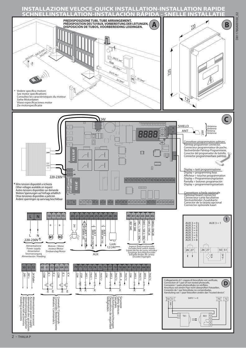
4) TUBE ARRANGEMENT Fi g. A
5) TERMINAL BOARD WIRING Fig. CWARNINGS - When performing wiring and installation, refer to the standards in force and, whatever the case, apply good practice principles.Wires carrying different voltages must be kept physically separate from each other, or they must be suitably insulated with at least 1mm of additional insulation. Wires must be secured with additional fastening near the terminals, using devices such as cable clamps.All connecting cables must be kept far enough away from the dissipater.
Terminal Definition Description
Pow
er s
uppl
y
L LINESingle-phase power supply 220-230V 50/60Hz(*)
N NEUTRAL
JP5TRANSF PRIM Transformer primary winding connection, 220-230V.
JP7
JP21 TRANSF SECBoard power supply: 24V~ Transformer secondary winding 24V= Buffer battery power supply
Mot
or
10 MOT1 + Connection motor 1. Time lag during closing.Check connections shown in Fig.E11 MOT1 -
14 MOT2 + Connection motor 2. Time lag during opening.Check connections shown in Fig.E15 MOT2 -
Aux
20LIgHT 24v Flashing light 24V output max. 25W.
21
22AUX 1 -
220-230V~ POWERED CONTACT (Max. 5A)
AUX 1 configurable output - Default setting ZONE LIgHT Output. 2ND RADIO CHANNEL/ SCA gATE OPEN LIgHT/ COURTESY LIgHT/ ZONE LIgHT/ STAIR LIgHT/ gATE OPEN ALARM/ FLASHINg LIgHT/ SOLENOID LATCH/ MAgNETIC LOCK. Refer to “AUX output configuration” table.23
24 AUX 2 - FREE CONTACT
(N.O.) (Max. 220-230V
5A)
AUX 2 configurable output - Default setting SCA gATE OPEN LIgHT Output. 2ND RADIO CHANNEL/ SCA gATE OPEN LIgHT/ COURTESY LIgHT command/ ZONE LIgHT command/ STAIR LIgHT/ gATE OPEN ALARM/ FLASHINg LIgHT/ SOLENOID LATCH/ MAgNETIC LOCK. Refer to “AUX output configuration” table.25
26AUX 3 - FREE
CONTACT (N.O.)
(Max. 24V 1A)
AUX 3 configurable output - Default setting 2ND RADIO CHANNEL Output. 2ND RADIO CHANNEL/ SCA gATE OPEN LIgHT/ COURTESY LIgHT command/ ZONE LIgHT command/ STAIR LIgHT/ gATE OPEN ALARM/ FLASHINg LIgHT/ SOLENOID LATCH/ MAgNETIC LOCK. Refer to “AUX output configuration” table.27
28LOCK 12V/24
Type of lock logic= 0 - 12V solenoid latch output (max. 30W). Output activated with a pulse each time gate is opened.Type of lock logic= 1 - 12V magnetic lock output (max. 15W). Output activated when gate is closed.
29 Type of lock logic= 2 - 24V solenoid latch output (max. 30W). Output activated with a pulse each time gate is opened.Type of lock logic= 3 - 24V magnetic lock output (max. 15W). Output activated when gate is closed.
Lim
it s
wit
ch fo
r EL
I 250
BT
41 + REF SWE Limit switch common
42 SWC 1 Motor 1 closing limit switch SWC1 (N.C.).
43 SWO 1 Motor 1 opening limit switch SWO1 (N.C.).
44 SWC 2 Motor 2 closing limit switch SWC2 (N.C.).
45 SWO 2 Motor 2 opening limit switch SWO2 (N.C.).
Lim
it s
wit
ch fo
r PH
OBO
S BT
- IG
EA B
T - S
UB
BT
42 SW 1 Limit switch control motor 1. For actuators with single-wire limit switch control.
43 SW 2 Limit switch control motor 2. For actuators with single-wire limit switch control.
ENG
LISH
THALIA P 31
D81
1780
A00
100_
02

INSTALLATION MANUALTerminal Definition Description
Lim
it s
wit
ch
for
LUX
BTLU
X G
BT 41 + REF SWE Limit switch common
42 SW 1 Limit switch control motor 1.
43 SW 2 Limit switch control motor 2.
Acc
esso
ries
pow
er s
uppl
y 50 24V-Accessories power supply output.
51 24V+
52 24 Vsafe+ Tested safety device power supply output (photocell transmitter and safety edge transmitter). Output active only during operating cycle.
Com
man
ds
60 Common IC 1 and IC 2 inputs common
61 IC 1Configurable command input 1 (N.O.) - Default START E. START E / START I / OPEN / CLOSE / PED / TIMER / TIMER PED Refer to the “Command input configuration” table.
62 IC 2Configurable command input 2 (N.O.) - Default PED. START E / START I / OPEN / CLOSE / PED / TIMER / TIMER PED Refer to the “Command input configuration” table.
63 Common IC 3 and IC 4 inputs common
64 IC 3Configurable command input 3 (N.O.) - Default OPEN. START E / START I / OPEN / CLOSE / PED / TIMER / TIMER PED Refer to the “Command input configuration” table.
65 IC 4Configurable command input 4 (N.O.) - Default CLOSE. START E / START I / OPEN / CLOSE / PED / TIMER / TIMER PED Refer to the “Command input configuration” table.
Safe
ty d
evic
es
70 Common STOP, SAFE 1 and SAFE 2 inputs common
71 STOP The command stops movement. (N.C.) If not used, leave jumper inserted.
72 SAFE 1Configurable safety input 1 (N.C.) - Default PHOT. PHOT / PHOT TEST / PHOT OP / PHOT OP TEST / PHOT CL / PHOT CL TEST / BAR / BAR TEST / BAR 8K2 Refer to the “Safety input configuration” table.
73 FAULT 1 Test input for safety devices connected to SAFE 1.
74 SAFE 2Configurable safety input 2 (N.C.) - Default BAR. PHOT / PHOT TEST / PHOT OP / PHOT OP TEST / PHOT CL / PHOT CL TEST / BAR / BAR TEST / BAR 8K2 Refer to the “Safety input configuration” table.
75 FAULT 2 Test input for safety devices connected to SAFE 2.
76 Common SAFE 3 and SAFE 4 inputs common
77 SAFE 3Configurable safety input 3 (N.C.) - Default PHOT OP. PHOT / PHOT TEST / PHOT OP / PHOT OP TEST / PHOT CL / PHOT CL TEST / BAR / BAR TEST / BAR 8K2 Refer to the “Safety input configuration” table.
78 FAULT 3 Test input for safety devices connected to SAFE 3.
79 SAFE 4Configurable safety input 4 (N.C.) - Default PHOT CL. PHOT / PHOT TEST / PHOT OP / PHOT OP TEST / PHOT CL / PHOT CL TEST / BAR / BAR TEST / BAR 8K2 Refer to the “Safety input configuration” table.
80 FAULT 4 Test input for safety devices connected to SAFE 4.
81 Common SAFE 5 and SAFE 6 inputs common
82 SAFE 5Configurable safety input 5 (N.C.) - Default PHOT. PHOT / PHOT TEST / PHOT OP / PHOT OP TEST / PHOT CL / PHOT CL TEST / BAR / BAR TEST / BAR 8K2 Refer to the “Safety input configuration” table.
83 FAULT 5 Test input for safety devices connected to SAFE 5.
84 SAFE 6Configurable safety input 6 (N.C.) - Default BAR. PHOT / PHOT TEST / PHOT OP / PHOT OP TEST / PHOT CL / PHOT CL TEST / BAR / BAR TEST / BAR 8K2 Refer to the “Safety input configuration” table.
85 FAULT 6 Test input for safety devices connected to SAFE 6.
Ant
enna Y ANTENNA Antenna input.
Use an antenna tuned to 433MHz. Use Rg58 coax cable to connect the Antenna and Receiver. Metal bodies close to the antenna can interfere with radio reception. If the transmitter’s range is limited, move the antenna to a more suitable position.# SHIELD
AUX output configuration
Aux logic= 0 - 2ND RADIO CHANNEL output. Contact stays closed for 1s when 2nd radio channel is activated.
Aux logic= 1 - SCA gATE OPEN LIgHToutput. Contact stays closed during opening and with leaf open, intermittent during closing, open with leaf closed.
Aux logic= 2 - COURTESY LIgHT command output. Contact stays on for 90 seconds after the last operation.
Aux logic= 3 - ZONE LIgHT command output. Contact stays closed for the full duration of operation.
Aux logic= 4 - STAIR LIgHT output. Contact stays closed for 1 second at start of operation.
Aux logic= 5 - gATE OPEN ALARM output. Contact stays closed if the leaf stays open for double the set TCA time.
Aux logic= 6 - FLASHINg LIgHT output. Contact stays closed while leaves are operating.
Aux logic= 7 - SOLENOID LATCH output. Contact stays closed for 2 seconds each time gate is opened.
Aux logic= 8 - MAgNETIC LOCK output. Contact stays closed while gate is closed.
Command input configuration
IC logic= 0 - Input configured as Start E. Operation according to STEP-BY-STEP MOV. logic. External start for traffic light control.
32 - THALIA P
D81
1780
A00
100_
02
IC logic= 1 - Input configured as Start I. Operation according to STEP-BY-STEP MOV. logic. Internal start for traffic light control.
IC logic= 2 - Input configured as Open. The command causes the leaves to open. If the input stays closed, the leaves stay open until the contact is opened. When the contact is open, the automated device closes following the TCA time, where activated.
IC logic= 3 - Input configured as Closed. The command causes the leaves to close.
IC logic= 4 - Input configured as Ped. The command causes the leaf to open to the pedestrian (partial) opening position. Operation according to STEP-BY-STEP. logic
IC logic= 5 - Input configured as Timer. Operation same as open except closing is guaranteed even after a mains power outage.
IC logic= 6 - Input configured as Timer Ped. The command causes the leaf to open to the pedestrian (partial) opening position. If the input stays closed, the leaf stays open until the contact is opened. If the input stays closed and a Start E, Start I or Open command is activated, a complete opening-closing cycle is performed before returning to the pedestrian opening position. Closing is guaranteed even after a mains power outage.
Safety input configuration
SAFE logic= 0 - Input configured as Phot (photocell) non tested (*). (fig.F, ref.1). Enables connection of devices not equipped with supplementary test contacts. When beam is broken, photocells are active during both opening and closing. When beam is broken during closing, movement is reversed only once the photocell is cleared. If not used, leave jumper inserted.
SAFE logic= 1 - Input configured as Phot test (tested photocell). (fig.F, ref.2). Switches photocell testing on at start of operation. When beam is broken, photocells are active during both opening and closing. When beam is broken during closing, movement is reversed only once the photocell is cleared.
SAFE logic= 2 - Input configured as Phot op (photocell active during opening only) non tested (*). (fig.F, ref.1). Enables connection of devices not equipped with supplementary test contacts. In the event beam is broken, photocell operation is disabled during closing. During opening, stops motion for as long as the photocell beam stays broken. If not used, leave jumper inserted.
SAFE logic= 3 - Input configured as Phot op test (tested photocell active during opening only (fig.F, ref.2). Switches photocell testing on at start of operation. In the event beam is broken, photocell operation is disabled during closing. During opening, stops motion for as long as the photo-cell beam stays broken.
SAFE logic= 4 - Input configured as Phot cl (photocell active during closing only) non tested (*). (fig.F, ref.1). Enables connection of devices not equipped with supplementary test contacts. In the event beam is broken, photocell operation is disabled during opening. During closing, move-ment is reversed immediately. If not used, leave jumper inserted.
SAFE logic= 5 - Input configured as Phot cl test (tested photocell active during closing only (fig.F, ref.2). Switches photocell testing on at start of operation. In the event beam is broken, photocell operation is disabled during opening. During closing, movement is reversed immediately.
SAFE logic= 6 - Input configured as Bar (safety edge) non tested (*). (fig.F, ref.3). Enables connection of devices not equipped with supplementary test contacts. The command reverses movement for 2 sec.. If not used, leave jumper inserted.
SAFE logic= 7 - Input configured as Bar (tested safety edge (fig.F, ref.4). Switches safety edge testing on at start of operation. The command reverses movement for 2 sec.
SAFE logic= 8 - Input configured as Bar 8k2 (fig.F, ref.5). Input for resistive edge 8K2. The command reverses movement for 2 sec.
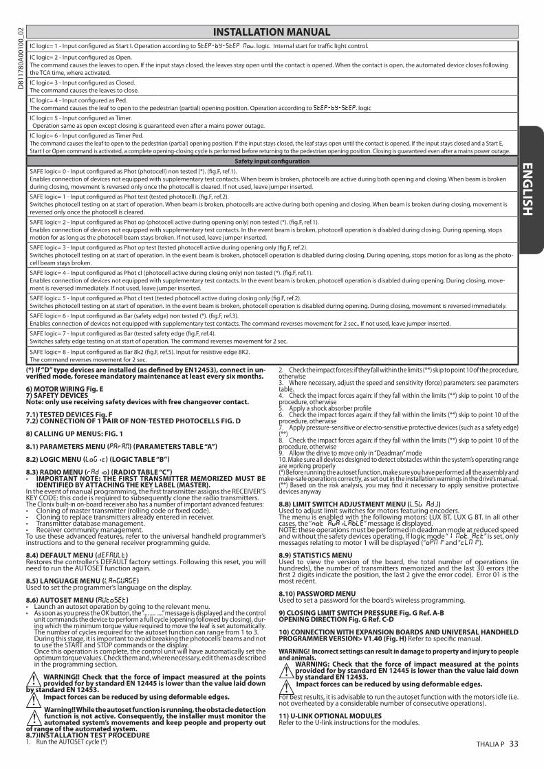
(*) If “D” type devices are installed (as defined by EN12453), connect in un-verified mode, foresee mandatory maintenance at least every six months. 6) MOTOR WIRING Fig. E7) SAFETY DEVICESNote: only use receiving safety devices with free changeover contact.
7.1) TESTED DEVICES Fig. F7.2) CONNECTION OF 1 PAIR OF NON-TESTED PHOTOCELLS FIG. D
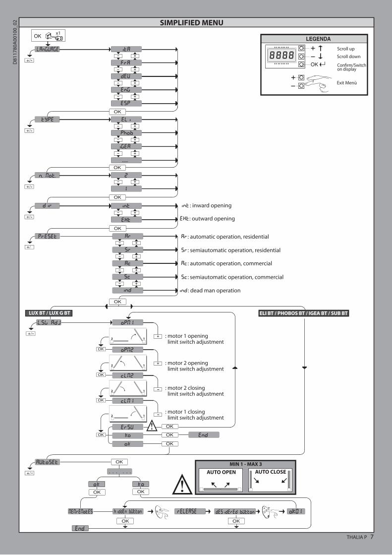
8) CALLING UP MENUS: FIG. 1
8.1) PARAMETERS MENU (PARA ) (PARAMETERS TABLE “A”)
8.2) LOGIC MENU (LOGIC) (LOGIC TABLE “B”)
8.3) RADIO MENU (radio) (RADIO TABLE “C”)- IMPORTANT NOTE: THE FIRST TRANSMITTER MEMORIZED MUST BE
IDENTIFIED BY ATTACHING THE KEY LABEL (MASTER).In the event of manual programming, the first transmitter assigns the RECEIVER’S KEY CODE: this code is required to subsequently clone the radio transmitters.The Clonix built-in on-board receiver also has a number of important advanced features: • Cloningofmastertransmitter(rollingcodeorfixedcode).• Cloningtoreplacetransmittersalreadyenteredinreceiver.• Transmitterdatabasemanagement.• Receivercommunitymanagement.To use these advanced features, refer to the universal handheld programmer’s instructions and to the general receiver programming guide.
8.4) DEFAULT MENU (default)Restores the controller’s DEFAULT factory settings. Following this reset, you will need to run the AUTOSET function again.
8.5) LANGUAGE MENU (language)Used to set the programmer’s language on the display.
8.6) AUTOSET MENU (AUTOset) • Launch an autoset operation by going to the relevant menu.• As soon as you press the OK button, the “.... .... ....” message is displayed and the control
unit commands the device to perform a full cycle (opening followed by closing), dur-ing which the minimum torque value required to move the leaf is set automatically.
The number of cycles required for the autoset function can range from 1 to 3. During this stage, it is important to avoid breaking the photocells’ beams and not
to use the START and STOP commands or the display. Once this operation is complete, the control unit will have automatically set the
optimum torque values. Check them and, where necessary, edit them as described in the programming section.
WARNING!! Check that the force of impact measured at the points provided for by standard EN 12445 is lower than the value laid down
by standard EN 12453.Impact forces can be reduced by using deformable edges.
Warning!! While the autoset function is running, the obstacle detection function is not active. Consequently, the installer must monitor the automated system’s movements and keep people and property out
of range of the automated system.8.7)INSTALLATION TEST PROCEDURE1. Run the AUTOSET cycle (*)
2. Check the impact forces: if they fall within the limits (**) skip to point 10 of the procedure, otherwise3. Where necessary, adjust the speed and sensitivity (force) parameters: see parameters table.4. Check the impact forces again: if they fall within the limits (**) skip to point 10 of the procedure, otherwise5. Apply a shock absorber profile6. Check the impact forces again: if they fall within the limits (**) skip to point 10 of the procedure, otherwise7. Apply pressure-sensitive or electro-sensitive protective devices (such as a safety edge) (**)8. Check the impact forces again: if they fall within the limits (**) skip to point 10 of the procedure, otherwise9. Allow the drive to move only in “Deadman” mode10. Make sure all devices designed to detect obstacles within the system’s operating range are working properly(*) Before running the autoset function, make sure you have performed all the assembly and make-safe operations correctly, as set out in the installation warnings in the drive’s manual.(**) Based on the risk analysis, you may find it necessary to apply sensitive protective devices anyway
8.8) LIMIT SWITCH ADJUSTMENT MENU (L.SW ADJ)Used to adjust limit switches for motors featuring encoders. The menu is enabled with the following motors: LUX BT, LUX g BT. In all other cases, the “NOT AVAILABLE” message is displayed. NOTE: these operations must be performed in deadman mode at reduced speed and without the safety devices operating. If logic mode “1 Mot. act” is set, only messages relating to motor 1 will be displayed (“OPm1” and “CLm1”).
8.9) STATISTICS MENUUsed to view the version of the board, the total number of operations (in hundreds), the number of transmitters memorized and the last 30 errors (the first 2 digits indicate the position, the last 2 give the error code). Error 01 is the most recent.
8.10) PASSWORD MENU Used to set a password for the board’s wireless programming.
9) CLOSING LIMIT SWITCH PRESSURE Fig. G Ref. A-BOPENING DIRECTION Fig. G Ref. C-D
10) CONNECTION WITH EXPANSION BOARDS AND UNIVERSAL HANDHELD PROGRAMMER VERSION> V1.40 (Fig. H) Refer to specific manual.
WARNING! Incorrect settings can result in damage to property and injury to people and animals.
WARNING: Check that the force of impact measured at the points provided for by standard EN 12445 is lower than the value laid down by standard EN 12453.Impact forces can be reduced by using deformable edges.
For best results, it is advisable to run the autoset function with the motors idle (i.e. not overheated by a considerable number of consecutive operations).
11) U-LINK OPTIONAL MODULESRefer to the U-link instructions for the modules.
INSTALLATION MANUALEN
GLISH
THALIA P 33
D81
1780
A00
100_
02
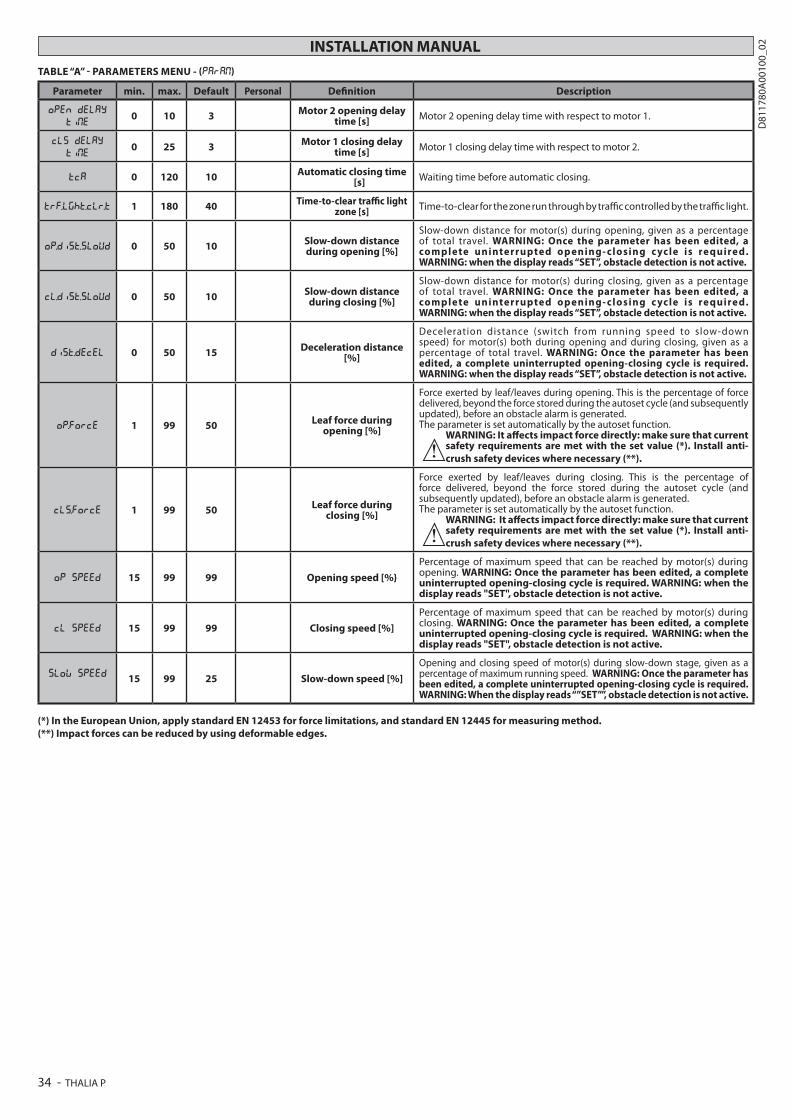
INSTALLATION MANUALTABLE “A” - PARAMETERS MENU - (PARA )
Parameter min. max. Default Personal Definition Description
OPEN DELAY
TI E0 10 3 Motor 2 opening delay
time [s] Motor 2 opening delay time with respect to motor 1.
CLS DELAY
TI E0 25 3 Motor 1 closing delay
time [s] Motor 1 closing delay time with respect to motor 2.
TCA 0 120 10 Automatic closing time [s] Waiting time before automatic closing.
TRF.LGHT.CLR.T 1 180 40 Time-to-clear traffic light zone [s] Time-to-clear for the zone run through by traffic controlled by the traffic light.
OP.DIST.SLOUD 0 50 10 Slow-down distance during opening [%]
Slow-down distance for motor(s) during opening, given as a percentage of total travel. WARNING: Once the parameter has been edited, a complete uninterrupted opening- closing c ycle is required. WARNING: when the display reads “SET”, obstacle detection is not active.
CL.DIST.SLOUD 0 50 10 Slow-down distance during closing [%]
Slow-down distance for motor(s) during closing, given as a percentage of total travel. WARNING: Once the parameter has been edited, a complete uninterrupted opening- closing c ycle is required. WARNING: when the display reads “SET”, obstacle detection is not active.
DIST.DECEL 0 50 15 Deceleration distance [%]
Deceleration distance (switch from running speed to slow-down speed) for motor(s) both during opening and during closing, given as a percentage of total travel. WARNING: Once the parameter has been edited, a complete uninterrupted opening-closing cycle is required. WARNING: when the display reads “SET”, obstacle detection is not active.
OP.FORCE 1 99 50 Leaf force during opening [%]
Force exerted by leaf/leaves during opening. This is the percentage of force delivered, beyond the force stored during the autoset cycle (and subsequently updated), before an obstacle alarm is generated.The parameter is set automatically by the autoset function.
WARNING: It affects impact force directly: make sure that current safety requirements are met with the set value (*). Install anti-crush safety devices where necessary (**).
CLS.FORCE 1 99 50 Leaf force during closing [%]
Force exerted by leaf/leaves during closing. This is the percentage of force delivered, beyond the force stored during the autoset cycle (and subsequently updated), before an obstacle alarm is generated.The parameter is set automatically by the autoset function.
WARNING: It affects impact force directly: make sure that current safety requirements are met with the set value (*). Install anti-crush safety devices where necessary (**).
OP SPEED 15 99 99 Opening speed [%}Percentage of maximum speed that can be reached by motor(s) during opening. WARNING: Once the parameter has been edited, a complete uninterrupted opening-closing cycle is required. WARNING: when the display reads "SET", obstacle detection is not active.
CL SPEED 15 99 99 Closing speed [%]Percentage of maximum speed that can be reached by motor(s) during closing. WARNING: Once the parameter has been edited, a complete uninterrupted opening-closing cycle is required. WARNING: when the display reads "SET", obstacle detection is not active.
SLOW SPEED 15 99 25 Slow-down speed [%]Opening and closing speed of motor(s) during slow-down stage, given as a percentage of maximum running speed. WARNING: Once the parameter has been edited, a complete uninterrupted opening-closing cycle is required. WARNING: When the display reads “”SET””, obstacle detection is not active.
(*) In the European Union, apply standard EN 12453 for force limitations, and standard EN 12445 for measuring method.(**) Impact forces can be reduced by using deformable edges.
34 - THALIA P
D81
1780
A00
100_
02

TABLE “B” - LOGIC MENU - (logic)
INSTALLATION MANUAL
Logic Definition DefaultCross out
settingused
Optional extras
MOTOR TYPE
Motor type
(Set the type of motor connected to the
board).
0
0 Motors not active
1 ELI 250 BT
2 PHOBOS BT
3 IgEA BT
4 LUX BT
5 LUX g BT
6 SUB BT
TCAAutomatic Closing
Time 0 0 Logic not enabled
1 Switches automatic closing on
FAST CLS. Fast closing 0 0 Logic not enabled
1 Closes 3 seconds after the photocells are cleared before waiting for the set TCA to elapse.
STEP-BY-STEP
MOVEMNT
Step-by-stepmovement 0
0 Inputs configured as Start E, Start I, Ped operate with 4-step logic. step-by-step mov.
2 STEP 3 STEP 4 STEP
CLOSEDOPENS OPENS
OPENS
DURINg CLOSINg STOPS
OPENCLOSES
CLOSES CLOSES
DURINg OPENINg STOP + TCA STOP + TCA
AFTER STOP OPENS OPENS OPENS
1Inputs configured as Start E, Start I, Ped operate with 3-step logic. Pulse during closing reverses movement.
2Inputs configured as Start E, Start I, Ped operate with 2-step logic. Move-ment reverses with each pulse.
PRE-ALARM Pre-alarm 0 0 The flashing light comes on at the same time as the motor(s) start.
1 The flashing light comes on approx. 3 seconds before the motor(s) start.
HOLD-TO-RUN Deadman 0
0 Pulse operation.
1
Deadman mode. Input 61 is configured as OPEN UP. Input 62 is configured as CLOSE UP. Operation continues as long as the OPEN UP or CLOSE UP keys are held down.
WARNING: safety devices are not enabled.
2
Emergency Deadman mode. Usually pulse operation. If the board fails the safety device tests (photocell or safety edge, Er0x) 3 times in a row, the device is switched to Deadman mode, which will stay active until the OPEN UP or CLOSE UP keys are released. Input 61 is configured as OPEN UP. Input 62 is configured as CLOSE UP.
WARNING: with the device set to Emergency Deadman mode, safety devices are not enabled.
IBL OPENBlock pulses during
opening 0 0 Pulse from inputs configured as Start E, Start I, Ped has effect during opening.
1 Pulse from inputs configured as Start E, Start I, Ped has no effect during opening.
|IBL TCABlock pulses during
TCA 0 0 Pulse from inputs configured as Start E, Start I, Ped has effect during TCA pause.
1 Pulse from inputs configured as Start E, Start I, Ped has no effect during TCA pause.
IBL CLOSEBlock pulses during
closing 0 0 Pulse from inputs configured as Start E, Start I, Ped has effect during closing.
1 Pulse from inputs configured as Start E, Start I, Ped has no effect during closing.
RAM BLOW C.OPHammer during
opening 0
0 Logic not enabled
1Before opening completely, the gate pushes for approx. 2 seconds as it closes. This allows the sole-noid lock to be released more easily. IMPORTANT - Do not use this function if suitable mechanical stops are not in place.
RAM BLOW C.CLHammer during
closing 0
0 Logic not enabled
1Before closing completely, the gate pushes for approx. 2 seconds as it opens. This allows the solenoid lock to be released more easily. IMPORTANT - Do not use this function if suitable mechanical stops are not in place.
BLOC PERSIST Stop maintenance 0
0 Logic not enabled
1
If motors stay idle in fully open or fully closed position for more than one hour, they are switched on in the direction of the stop for approx. 3 seconds. This operation is performed every hour. NB: In hydraulic motors, this function serves to compensate a possible reduction in the volume of oil due to a drop in temperature during extended pauses, such as during the night, or due to internal leakage. IMPORTANT - Do not use this function if suitable mechanical stops are not in place.
ENG
LISH
THALIA P 35
D81
1780
A00
100_
02

INSTALLATION MANUAL
Logic Definition DefaultCross out
settingused
Optional extras
PRESS SWCClosing limit switch
pressure 0
0 Movement is stopped only when the closing limit switch trips: in this case, the tripping of the closing limit switch must be adjusted accurately (Fig.g Ref.B).
1
Use when there is a mechanical stop in closed position. This function allows leaves to press against the mechanical stop without the Amperostop sensor interpreting this as an obstacle. Thus the rod continues its stroke for a few seconds after meeting the closing limit switch or as far as the mechanical stop. In this way, the leaves come to rest perfectly against the stop by allowing the closing limit switches to trip slightly earlier (Fig.g Ref.A).
ICE Ice feature 0
0 The Amperostop safety trip threshold stays at the same set value.
1
The controller automatically adjusts the obstacle alarm trip threshold at each start up. Check that the force of impact measured at the points provided for by standard EN 12445 is lower than the value laid down by standard EN 12453. If in doubt, use auxiliary safety devices. This feature is useful when dealing with installations running at low temperatures. WARNINg: once this feature has been activated, you will need to perform an autoset opening and closing cycle.
1 MOT.ON 1 motor active 0 0 Both motors active (2 leaves).
1 Only motor 1 active (1 leaf ).
OPEN IN OTHER
DIRECT.
Open in other direction 0
0 Standard operating mode (See Fig.g Ref. C).
1 Opens in other direction to standard operating mode (See Fig. g Ref.D)
SAFE 1Configuration of
safety input SAFE 1. 72
0
0 Input configured as Phot (photocell).
1 Input configured as Phot test (tested photocell).
2 Input configured as Phot op (photocell active during opening only).
3 Input configured as Phot op test (tested photocell active during opening only).
SAFE 2Configuration of
safety input SAFE 2. 74
6
4 Input configured as Phot cl (photocell active during closing only).
5 Input configured as Phot cl test (tested photocell active during closing only).
6 Input configured as Bar, safety edge.
7 Input configured as Bar, tested safety edge.
8 Input configured as Bar 8k2.
SAFE 3Configuration of
safety input SAFE 3. 77
2
0 Input configured as Phot (photocell).
1 Input configured as Phot test (tested photocell).
SAFE 4Configuration of
safety input SAFE 4. 79
42 Input configured as Phot op (photocell active during opening only).
3 Input configured as Phot op test (tested photocell active during opening only).
SAFE 5Configuration of
safety input SAFE 4. 79
04 Input configured as Phot cl (photocell active during closing only).
5 Input configured as Phot cl test (tested photocell active during closing only).
SAFE 6Configuration of
safety input SAFE 6. 84
66 Input configured as Bar, safety edge.
7 Input configured as Bar, tested safety edge.
IC 1Configuration of
command input IC 1. 61
0
0 Input configured as Start E.
1 Input configured as Start I.
IC 2Configuration of
command input IC 2. 62
4
2 Input configured as Open.
3 Input configured as Close.
IC 3Configuration of
command input IC 3. 64
2
4 Input configured as Ped.
5 Input configured as Timer.
IC 4Configuration of
command input IC 4. 65
3 6 Input configured as Timer Pedestrian.
36 - THALIA P
D81
1780
A00
100_
02
INSTALLATION MANUAL
Logic Definition DefaultCross out
settingused
Optional extras
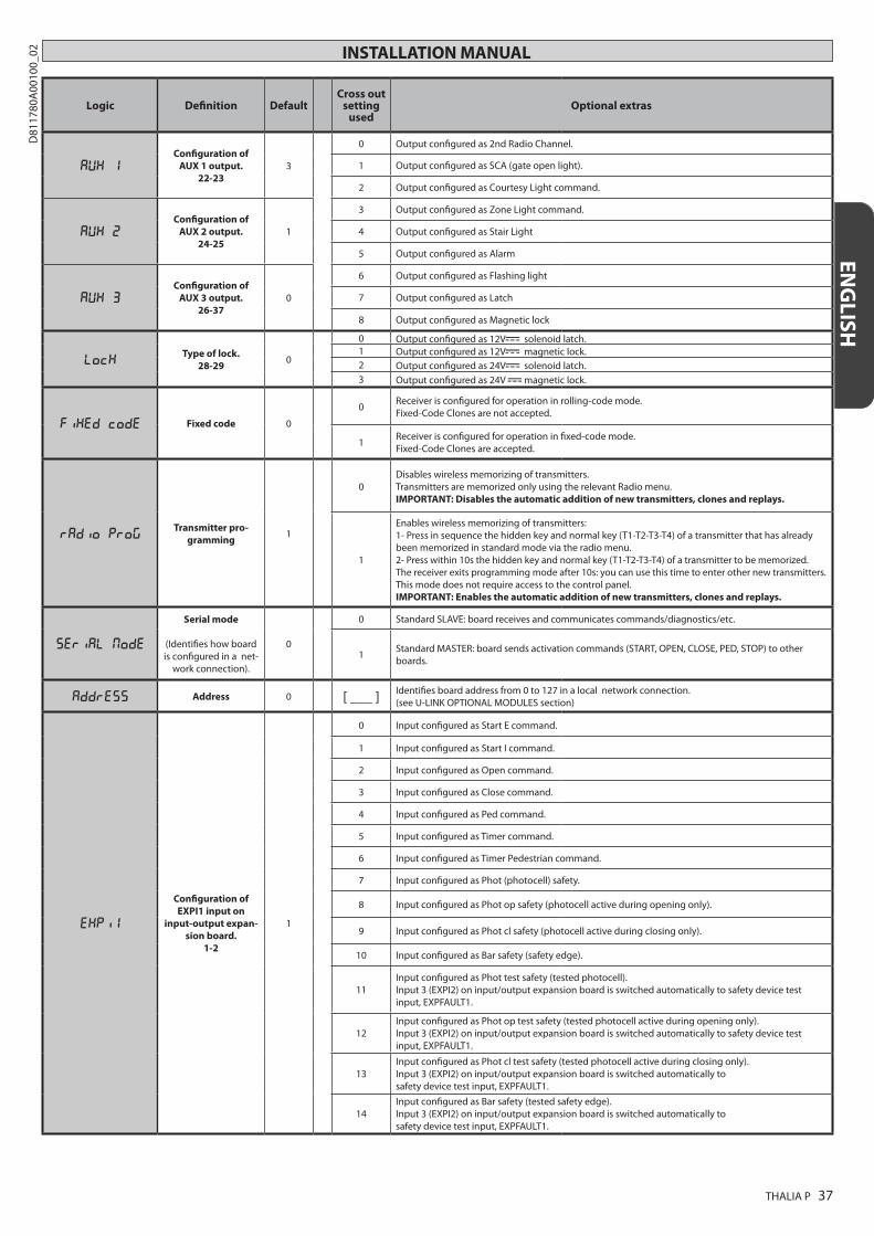
AUX 1Configuration of
AUX 1 output. 22-23
3
0 Output configured as 2nd Radio Channel.
1 Output configured as SCA (gate open light).
2 Output configured as Courtesy Light command.
AUX 2Configuration of
AUX 2 output. 24-25
1
3 Output configured as Zone Light command.
4 Output configured as Stair Light
5 Output configured as Alarm
AUX 3Configuration of
AUX 3 output. 26-37
0
6 Output configured as Flashing light
7 Output configured as Latch
8 Output configured as Magnetic lock
LOCKType of lock.
28-29 0
0 Output configured as 12V solenoid latch.1 Output configured as 12V magnetic lock.2 Output configured as 24V solenoid latch.3 Output configured as 24V magnetic lock.
FIXED CODE Fixed code 0
0 Receiver is configured for operation in rolling-code mode. Fixed-Code Clones are not accepted.
1 Receiver is configured for operation in fixed-code mode. Fixed-Code Clones are accepted.
RADIO PROGTransmitter pro-
gramming 1
0Disables wireless memorizing of transmitters. Transmitters are memorized only using the relevant Radio menu. IMPORTANT: Disables the automatic addition of new transmitters, clones and replays.
1
Enables wireless memorizing of transmitters: 1- Press in sequence the hidden key and normal key (T1-T2-T3-T4) of a transmitter that has already been memorized in standard mode via the radio menu. 2- Press within 10s the hidden key and normal key (T1-T2-T3-T4) of a transmitter to be memorized. The receiver exits programming mode after 10s: you can use this time to enter other new transmitters. This mode does not require access to the control panel. IMPORTANT: Enables the automatic addition of new transmitters, clones and replays.
SERIAL MODE
Serial mode
(Identifies how board is configured in a net-
work connection).
0
0 Standard SLAVE: board receives and communicates commands/diagnostics/etc.
1 Standard MASTER: board sends activation commands (START, OPEN, CLOSE, PED, STOP) to other boards.
ADDRESS Address 0 [ ___ ] Identifies board address from 0 to 127 in a local network connection. (see U-LINK OPTIONAL MODULES section)
EXPI1
Configuration of EXPI1 input on
input-output expan-sion board.
1-2
1
0 Input configured as Start E command.
1 Input configured as Start I command.
2 Input configured as Open command.
3 Input configured as Close command.
4 Input configured as Ped command.
5 Input configured as Timer command.
6 Input configured as Timer Pedestrian command.
7 Input configured as Phot (photocell) safety.
8 Input configured as Phot op safety (photocell active during opening only).
9 Input configured as Phot cl safety (photocell active during closing only).
10 Input configured as Bar safety (safety edge).
11Input configured as Phot test safety (tested photocell). Input 3 (EXPI2) on input/output expansion board is switched automatically to safety device test input, EXPFAULT1.
12Input configured as Phot op test safety (tested photocell active during opening only). Input 3 (EXPI2) on input/output expansion board is switched automatically to safety device test input, EXPFAULT1.
13Input configured as Phot cl test safety (tested photocell active during closing only). Input 3 (EXPI2) on input/output expansion board is switched automatically to safety device test input, EXPFAULT1.
14Input configured as Bar safety (tested safety edge). Input 3 (EXPI2) on input/output expansion board is switched automatically to safety device test input, EXPFAULT1.
ENG
LISH
THALIA P 37
D81
1780
A00
100_
02

TABLE “C” – RADIO MENU (RADIO)
Logic Description
Add startAdd Start Keyassociates the desired key with the Start command
add 2chAdd 2ch Keyassociates the desired key with the 2nd radio channel command. Associates the desired key with the 2nd radio channel command. If no output is configured as 2nd Radio Channel Output, the 2nd radio channel controls the pedestrian opening.
erase 64Erase List
WARNING! Erases all memorized transmitters from the receiver’s memory.
Read receiver codeDisplays receiver code required for cloning transmitters.
ON = Enables remote programming of cards via a previously memorized W LINK transmitter. It remains enabled for 3 minutes from the time the W LINK transmitter is last pressed.OFF= W LINK programming disabled.
Logic Definition DefaultCross out
settingused
Optional extras
EXPI2
Configuration of EXPI2 input
on input-output expansion board.
1-3
0
0 Input configured as Start E command.
1 Input configured as Start I command.
2 Input configured as Open command.
3 Input configured as Close command.
4 Input configured as Ped command.
5 Input configured as Timer command.
6 Input configured as Timer Pedestrian command.
7 Input configured as Phot (photocell) safety.
8 Input configured as Phot op safety (photocell active during opening only).
9 Input configured as Phot cl safety (photocell active during closing only).
10 Input configured as Bar safety (safety edge).
EXPO1
Configuration of EXPO2 output
on input-output expansion board
4-5
9
0 Output configured as 2nd Radio Channel.
1 Output configured as SCA (gate open light).
2 Output configured as Courtesy Light command.
3 Output configured as Zone Light command.
4 Output configured as Stair Light.
EXPO2
Configuration of EXPO2 output
on input-output expansion board
6-7
9
5 Output configured as Alarm.
6 Output configured as Flashing light.
7 Output configured as Latch.
8 Output configured as Magnetic lock.
9 Output configured as Traffic Light control with TLB board.
TRAFFIC LIGHT
PREFLASHING
Traffic light pre-flashing 0
0 Pre-flashing switched off.
1 Red lights flash, for 3 seconds, at start of operation.
TRAFFIC LIGHT
RED LAMP
ALWAYS ON
Steadily lit red light 0
0 Red lights off when gate closed.
1 Red lights on when gate closed.
38 - THALIA P
D81
1780
A00
100_
02