Serie F8 - hatecflex.de file2. VALVES. Serie F8. Flanged Elastic Rubber Joint / Gummikompensator mit...
8
F8_07/02/2018 DOWNLOAD DATASHEET VALVES -Smart, Be-Brandoni Serie F8 Flanged Elastic Rubber Joint Gummikompensator mit Flansch 1 www.hatecflex.de www.brandonivalves.it
Transcript of Serie F8 - hatecflex.de file2. VALVES. Serie F8. Flanged Elastic Rubber Joint / Gummikompensator mit...
F8
_07/
02/
2018
DOWNLOADDATASHEET
VALVES
-Smart, Be-Brandoni
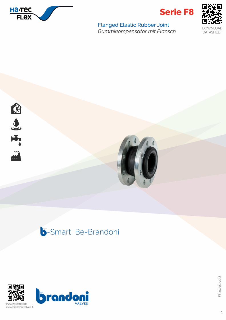
Serie F8Flanged Elastic Rubber Joint Gummikompensator mit Flansch
1
www.hatecflex.de www.brandonivalves.it

2 VA
LVES
Serie F8Flanged Elastic Rubber Joint / Gummikompensator mit Flansch
Gummikompensatoren schützen die Anlagen vor Dehnung,
Kompression und Biegung. Außerdem üben sie eine
schwingungs- und schalldämpfende Wirkung aus und tragen
zu einer Reduzierung von Druckstößen bei. Erhältlich in
folgenden Ausführungen:
F8.1 > NBR
F8.5 > EPDM
F8.508 > EPDM mit WRAS-Zulassung
Geeignet für: Wasser-, Pump-, Heiz- und Klimaanlagen, Indu-
strie und Landwirtschaft, Druckluft.
Zubehör Längenbegrenzer
Certifications / Zertifizierungen
Serie F8.5
Entspricht dem Ministerialerlass 174 (Richtlinie 98/83/EG) für
die Verwendung mit Trinkwasser.
Serie F8.508 Zertifizierung WRAS
Bau- und Abnahmenormen (äquivalent):Flanschtypen: EN 1092
Elastic joints protect the piping from extension, compression,
misalignments and bending. Suitable for reducing vibrations
and noise absorption, allowing the further reduction of the
effects of water hammers.
Available in versions:
F8.1 > NBR
F8.5 > EPDM
F8.508 > EPDM WRAS approved
YES: for water plants, pumping stations, conditioning
and heating, industrial and agricultural
applications, compressed air circuits.
AccessoriesControl rod unit
Series F8.5
Suitable for drinking water applications, comply with
Italian regulation D.M.174.
Serie F8.508 WRAS certificated
Design and testing standards (correspondences): Flanges: EN 1092
Hatec Flex GmbH - Hafenstraße 25 - 45478 Mülheim a. d. Ruhr - Deutschland - 0208/377987135 - www.hatecflex.de/armaturen - [email protected]

VA
LVES
3
Reinforcing fabric.
Mehrschicht-Gewebeverstärkung.
Reinforcing retaining ring.
Verstärkungs- und Sicherungsring.
Swivelling flange in galvanized
steel. On request, AISI 316.
Drehbare Flansche aus verzinktem
Stahl.
Auf Anfrage aus AISI 316.
DN 200-600: suitable for mounting
on flanges PN10 and PN 16.
ANSI 150 flanges on request.
DN 200-600: geeignet für die Mon-
tage an Flansche PN10 und PN 16.
Auf Anfrage Flansche aus ANSI 150.
Hatec Flex GmbH - Hafenstraße 25 - 45478 Mülheim a. d. Ruhr - Deutschland - 0208/377987135 - www.hatecflex.de/armaturen - [email protected]

4 VA
LVES
Serie F8Flanged Elastic Rubber Joint / Gummikompensator mit Flansch
F8.520
Body: EPDM Flanges: AISI 316 Temp: -10 +100°C
Gehäuse: EPDM Flansche: AISI 316 Temp: -10 +100°C
F8.120
Body: NBR Flanges: AISI 316 Temp: -10 +80°C
Gehäuse: NBR Flansche: AISI 316 Temp: -10 +80°C
F8.100
Body: NBRFlanges: galvanized steel Temp: -10 +80°C
Gehäuse: NBR Flansche: verzinkter Stahl Temp: -10 +80°C
F8. KIT
Control rod unit in galvanized carbon steel
Längenbegrenzer aus verzinktem Stahl
EPDM NBR
Accessoires /● Zubehör
F8.508
Body: EPDMFlanges: galvanized steel Temp: -10 +100°C
Gehäuse: EPDM Flansche: verzinkter Stahl Temp: -10 +100°C
F8.500
Body: EPDMFlanges: galvanized steel Temp: -10 +100°C
Gehäuse: EPDM Flansche: verzinkter Stahl Temp: -10 +100°C
EPDM
Hatec Flex GmbH - Hafenstraße 25 - 45478 Mülheim a. d. Ruhr - Deutschland - 0208/377987135 - www.hatecflex.de/armaturen - [email protected]

VA
LVES
5
(
DN 32 40 50 65 80 100 125 150 200 250 300 350 400 450 500 600A 93 93 99 108 116 129 142 156 177 206 217 266 266 200 200 250F 140 150 165 185 200 220 250 285 340 405 460 520 580 640 715 840C EN 1092
PN16
100 110 125 145 160 180 210 240 295 355 410 470 525 585 650 770n x D 4 x 18 4 x 18 4 x 18 4 x 18 8 x 18 8 x 18 8 x 18 8 x 22 12 x 22 12 x 27 12 x 26 16 x 26 16 x 30 20 x 30 20 x 33 20 x 36C1 EN 1092
PN10
100 110 125 145 160 180 210 240 295 355 400 460 515 565 620 725n1 x D1 4 x 18 4 x 18 4 x 18 4 x 18 8 x 18 8 x 18 8 x 18 8 x 22 8 x 22 12 x 27 12 x 22 16 x 22 16 x 26 20x 26 20x 26 20 x 30
Compression (mm) / Kompression (mm)
F8 8 8 8 12 12 12 16 16 20 20 20 25 25 20 20 20
Extension (mm) / Dehnung (mm)
F8 4 4 4 6 6 10 10 10 14 14 14 16 16 12 12 12
Lateral deflection (mm) / Seitliche Verschiebung (mm)
F8 ± 8 8 8 10 10 12 12 12 18 18 18 18 18 18 18 18
Angular deflection (degrees) / Biegung (Grad)
F8 ± 15 15 15 15 15 15 15 15 15 15 15 15 15 15 15 15
Weight (kg) / Gewicht (kg)
F8 2,80 3,80 4,20 4,80 6,30 7,20 9,30 11,60 17,50 25,50 31,50 44,10 53,80 61 82,20 120
124 3
DN
A
F
rev. 9/06/2017Cat2016_F8_sezdim+mat
DN
300-
600
F
PN16
n° x D
DN
200
C
PN10
/16
n° x D
PN16
C
Disposizione forature / Flange holes arrangement
n° x D
DN
32-1
50,D
N25
0
C
n1 x D1
PN10
C1
n1 x D1
PN10
C1
n° x Dn1 x D1
C C1
F
2 1 57 6
T
A1
P
Art.
F8
rev. 02/05/17Cat2016_F8-T8_p3.drw1_sezdim+mat
Art.
T8
DN300-600DN200DN32-150DN250
n° x D
F C
124 3A
DN
n° x D
FC
m
Notes on flange drilling and for expansion joints installationThe F8 series expansion joints can be installed between PN10 and PN16 flanges. For a correct installation rotate the flanges of the joint until you find the correspondence with ALL the holes of the counter flanges. For center distances and drilling diameters, see table.
Hinweise zur Flanschbohrung und Anbringung von Kompensatoren Gummikompensatoren der Serie F8 können zwischen Flanschen PN10 und PN16 montiert werden. Um eine korrekte Installation zu garantieren, müssen die Flansche der Kompensatoren so angepasst werden, dass sie mit ALLEN Bohrungen der Gegenflansche übereinstimmen. Für die Bohrungsabstände und –durchmesser siehe Tabelle.
Di ensions mm) / Maße (mm)
Materials / Werkstoffe
Component - Bauteil Material - Werkstoff
F8.1 F8.5
1 Body - Gehäuse NBR EPDM
2 Reinforcing fabric - Verstärkungsgewebe Nylon
3 Retaining ring - Sicherungsring Hard steel wire - Federstahl
4 Flange - Flansch Carbon steel, galvanised - Verzinkter C-Stahl
Hatec Flex GmbH - Hafenstraße 25 - 45478 Mülheim a. d. Ruhr - Deutschland - 0208/377987135 - www.hatecflex.de/armaturen - [email protected]

6 VA
LVES
Serie F8Flanged Elastic Rubber Joint / Gummikompensator mit Flansch
Minimum pressure (vacuum) / Mindestdruck (Vakuum)
Article - Artikel Bar
F8 0,7 bar absolut
Temperature / TemperaturTemperature - Temperatur min ° C max°C
EPDM -10 100
NBR -10 80
NB: the maximum working pressure decreases while the temperature increases; please refer to “pressure/temperature” chartAchtung: der max. Betriebsdruck reduziert sich mit steigenden Temperaturen, siehe „Druck-/Temperatur-Diagramm“.
Maximum pressure / Max. Druck
Fluids * Fluidtyp *
Hazardous gases G1 Gefährliche Gase G1 NO
Hazardous liquids L1 Gefährliche Flüssigkeiten L1
NO
Non hazardous gases G2 Ungefährliche Gase G2
16 bar DN15-5015 bar DN6512 bar DN80
Non hazardous liquids G2 Ungefährliche Flüssigkeit-en G2
16 bar
Water** Wasser**
16 bar
* hazardous gas, liquids acc. 2014/68/EU e 1272/2008 (CLP)** For supply, distribution and discharge of water (PED 2014/68/EU 1.1.2b* Gefährliche Gase und Flüssigkeiten gemäß 2014/68/EU und 1272/2008 (CLP) ** Für die Versorgung, die Verteilung und den Abfluss von Wasser (PED 2014/68/EU 1.1.2b)
Art. F8
28
87
142
psi
57
114
10
114
30 504020 60 70 80 90 °C
bar50 °F19417615814068 104 12286
16
12
8
4
10 °C9080706020 40 5030
bar
4
8
2
12
10
6
86 12210468 140 158 176 194 °F50
171
psi228
171
114
57
100
212
100
212
NBR
EPDM
2
14
10
6
14
158
EPDM
60
171
100
68 104
8
6
30 80
140
NBR
2
16 228Art. T8
86
10
50
12
20
574
psi
40
122
10
50
bar
°C
194176
70 90
°F212
Pressure/temperature chart Druck-/Temperatur-Diagramm
Hatec Flex GmbH - Hafenstraße 25 - 45478 Mülheim a. d. Ruhr - Deutschland - 0208/377987135 - www.hatecflex.de/armaturen - [email protected]

VA
LVES
7
DN
250
DN
125
101
100
1000
1000D
N 6
510 100
DN
150
DN
200
mc/h
DN
32
DN
40
DN
50
DN
80
DN
100
mmH2O
Head loss Fluid: water (1m H2O = 0,098bar)
Druckverluste Fluid: Wasser (1m H2O = 0,098bar)
Kv - DN chart / Tabelle Kv - DN
DN 20 25 32 40 50 65 80 100 125 150 200 250Kv mc/h - - 150,4 255 435 672 947 1.508 2.633 4.261 5.957 10.510
LAGERUNG - In einem geschlossenen und trockenen Raum aufbewahren.- Keiner direkten Sonneneinstrahlung aussetzen.
VERWENDUNG
- Die Verwendung von Längenbegrenzern ist notwendig, wenn die Verschiebungswerte höher als die gemäß Produktspezifikation zulässigen Werte sind. Sie ist vor allem empfehlenswert, wenn Pumpen oder andere nicht fest verankerte oder abgestützte Vorrichtungen vorhanden sind.- Hinweis: bei der Installation der Kompensatoren darauf achten, dass möglichst ihre neutrale (nicht verformte) Länge beibehalten bleibt. Eine übermäßige Dehnung/Kompression bei der Montage kann die Leistungen beeinträchtigen und zu Betriebsschäden führen.- Vor dem Kontakt zwischen Gummi und Flansch die Berührungsflächen reinigen;- Darauf achten, dass keine vorstehenden oder scharfkantigen Rohrabschnitte vorhanden sind, da sie Schäden an den Konta-ktflächen der Kupplung verursachen könnten;- Die Flansche nicht an das Rohr schweißen, wenn der Kompensator bereits montiert ist. Auf Funkenflug durch Schweiß-/Schleifarbeiten achten, die in Nähe von Kompensatoren durchgeführt werden, und entsprechende Schutzmaßnahmen ergreifen.- Die Schraube mit dem Kopf in Richtung Kompensator anbringen, damit der Gummi nicht beschädigt wird (Abb.1). Die Schrauben über Kreuz festziehen.
Anleitung und Hinweise für die Serie F8
STORING- Keep in a closed and dry place.- Avoid exposure to direct sunlight.
INSTALLATION- Control rods should be installed in case movement exceedsthe values permitted, indicated in the product specifications.The use is recommended when there are pumps or other de-vices being installed on springs or other elements not fixed orsupported.- Warning. Install the rubber joint respecting its unloadedlength. Compression or elongation deformation imposedduring joint installation could reduce performances andcause early wear and damages to joint.- Clean the surface before bringing the rubber and the flangeinto contact;- Ensure that protrusions and sharp edges on the piping do notcause damage to the contact surface of the joint;- Do not weld the flanges to the piping after installing the joint.Joints must be protected against sparks from any welding/grin-ding jobs carried out nearby.- Fit the screw to the flange, with the head of the screw in thedirection of the joint,to protect the rubber from damage (Fig. 1). Tighten the boltscrosswise.
Instruction and Recommendation for series F8
Hatec Flex GmbH - Hafenstraße 25 - 45478 Mülheim a. d. Ruhr - Deutschland - 0208/377987135 - www.hatecflex.de/armaturen - [email protected]

8 VA
LVES
- Die Kupplung nicht in direktem Kontakt mit Gummiober-flächen (z.B. Absperrklappen) montieren.- Keine Dichtungen zwischen der Kupplung und dem Gegen-flansch anbringen.- Direkte Sonneneinstrahlung vermeiden. Bei einer Montage imFreien gegebenenfalls angemessene Schutzabdeckungen vor-sehen.
WARTUNG
Keine Wartung notwendig.
INSTALLATION DER LÄNGENBEGRENZER
Zusammensetzung Set:
COMPONENT - BAUTEIL RODS - SPIN-DELN
PLATE - PLATTEN HEX NUTS - MUTTERN
Quantity - Menge 2 4 8
1. Die Platten P auf den Gegenflansch montieren (siehe Abb. 2)2. Die Spindel A an den Platten anbringen, indem man sie auf einer Seite mit den Muttern befestigt (z.B. D2 in der Abbildung).3. Den Abstand zwischen den Muttern (D1) und der Platte von dergegenüberliegenden Seite aus einstellen, indem man die für dieKupplung zulässige Dehngrenze (L) und Kompressionsgrenze (C)festlegt. Die in der Produktspezifikation angegebenen zulässigenWerte dürfen nicht überschritten werden.
FIG.1
D2 PA
LC
D1
FIG.2
ENTSORGUNG
Wenn der Kompensator beim Betrieb mit giftigen oder gefährlichen
Fluiden in Kontakt ist, müssen die notwendigen
Vorsichtsmaßnahmen getroffen werden, wobei eventuell im
Kompensator vorhandene Reste gründlich zu entfernen sind. Das
zuständige Personal muss angemessen geschult und mit der
notwendigen Schutzausrüstung ausgestattet werden. Vor der
Entsorgung den Kompensator zerlegen und seine Bestandteile
nach Materialtyp sortieren. Weitere Informationen hierzu finden
sich auch in den Produktbeschreibungen. Die getrennten Materialien
(z.B. Metalle) dem Recycling zuführen oder gemäß den geltenden
örtlichen Vorschriften umweltgerecht entsorgen.
.
Brandoni SpA reserves the right to make changes in design and/or construction of the products at any time without prior notice. For further information, please refer to www.brandonivalves.itDie in diesem Katalog genannten Daten und Merkmale haben lediglich Hinweischarakter. Brandoni S.p.A. behält sich vor, eines oder mehrere Merkmale der Ventile ohne Vorankündigung zu ändern. Weitere Informationen finden Sie unter www.brandonivalves.it.
- Do not install the joint in direct contact with a rubber surface(for example, butterfly valves).
- Do not place gaskets between the joint and counter flange.- Avoid exposure to direct sunlight. In the case of installingout-side, protect the joint,if necessary.
MAINTENANCE
The valve does not require maintenance.
INSTALLATION OF THE CONTROL ROD UNIT
The kit consists of:
1. Install the plates, P, on the counter flange (fig. 2)2. Fasten rod A to the plate with two nuts on one side (forexample, D2 – fig. 2).3. On the opposite side, regulate the distance between thenuts (D1) and the plate, thereby the extension (L) and thecompression limits (C) allowed for the joint.Do not exceed the maximum allowed values, indicated in thepro-duct specifications.
DISPOSAL
For valve operating with hazardous media (toxic, corrosive…) , if there
is a possibility of residue remaining in the valve, take due safety
precau-tion and carry out required cleaning operation. Personnel
in charge must be trained and equipped with appropriate protection
devices. Prior to disposal, disassemble the valve and separate the
component according to various materials. Please refer to product
literature for more information. Forward sorted material to
recycling (e.g. metallic materials) or disposal, according to local and
currently valid legisla-tion and under consideration of the
environment.
Hatec Flex GmbH - Hafenstraße 25 - 45478 Mülheim a. d. Ruhr - Deutschland - 0208/377987135 - www.hatecflex.de/armaturen - [email protected]