
SlimVent SVV80 · ELS-ZAS Anschlussstutzen Erforderlichfürzusätzliche Absaugstellen. Best.Nr.8184...
24
Flach-Radialrohrventilator Slim centrifugal fan box Groupe de ventilation extra-plat SlimVent SVV 80 – mit drei Betriebsstufen – with 3 speeds – à 3 vitesses de fonctionnement Helios Ventilatoren MONTAGE- UND BETRIEBSVORSCHRIFT NR. 86134 INSTALLATION AND OPERATING INSTRUCTIONS NO. 86134 NOTICE DE MONTAGE ET D’UTILISATION N° 86134 D UK F
Transcript of SlimVent SVV80 · ELS-ZAS Anschlussstutzen Erforderlichfürzusätzliche Absaugstellen. Best.Nr.8184...
Flach-RadialrohrventilatorSlim centrifugal fan boxGroupe de ventilation extra-plat
SlimVentSVV 80
– mit drei Betriebsstufen– with 3 speeds– à 3 vitesses de fonctionnement
Helios Ventilatoren
MONTAGE- UND BETRIEBSVORSCHRIFT NR. 86134
INSTALLATION AND OPERATING INSTRUCTIONS NO. 86134
NOTICE DE MONTAGE ET D’UTILISATION N° 86134
D
UK
F
Helios VentilatorenMONTAGE- UND BETRIEBSVORSCHRIFT NR. 86134
Inhaltsverzeichnis
KAPITEL 1. SLIMVENT SVV 80 SCHNELLÜBERSICHT . . . . . . . . . . . . . . . . . . . . . . . . . . . . . . . . . . . . . . . . . . . . Seite 21.0 Lieferumfang . . . . . . . . . . . . . . . . . . . . . . . . . . . . . . . . . . . . . . . . . . . . . . . . . . . . . . . . . . . . . . . . . . . . . . . . . Seite 21.1 Zubehör . . . . . . . . . . . . . . . . . . . . . . . . . . . . . . . . . . . . . . . . . . . . . . . . . . . . . . . . . . . . . . . . . . . . . . . . . . . . . Seite 2
KAPITEL 2. ALLGEMEINE HINWEISE . . . . . . . . . . . . . . . . . . . . . . . . . . . . . . . . . . . . . . . . . . . . . . . . . . . . . . . . . Seite 32.0 Wichtige Informationen . . . . . . . . . . . . . . . . . . . . . . . . . . . . . . . . . . . . . . . . . . . . . . . . . . . . . . . . . . . . . . . . . . Seite 32.1 Warn- und Sicherheitshinweise . . . . . . . . . . . . . . . . . . . . . . . . . . . . . . . . . . . . . . . . . . . . . . . . . . . . . . . . . . . Seite 32.2 Garantieansprüche – Haftungsausschluss . . . . . . . . . . . . . . . . . . . . . . . . . . . . . . . . . . . . . . . . . . . . . . . . . . . Seite 32.3 Vorschriften – Richtlinien . . . . . . . . . . . . . . . . . . . . . . . . . . . . . . . . . . . . . . . . . . . . . . . . . . . . . . . . . . . . . . . . . Seite 32.4 Sendungsannahme . . . . . . . . . . . . . . . . . . . . . . . . . . . . . . . . . . . . . . . . . . . . . . . . . . . . . . . . . . . . . . . . . . . . Seite 32.5 Einlagerung . . . . . . . . . . . . . . . . . . . . . . . . . . . . . . . . . . . . . . . . . . . . . . . . . . . . . . . . . . . . . . . . . . . . . . . . . . Seite 32.6 Einsatzbereich . . . . . . . . . . . . . . . . . . . . . . . . . . . . . . . . . . . . . . . . . . . . . . . . . . . . . . . . . . . . . . . . . . . . . . . . Seite 32.7 Leistungsdaten . . . . . . . . . . . . . . . . . . . . . . . . . . . . . . . . . . . . . . . . . . . . . . . . . . . . . . . . . . . . . . . . . . . . . . . . Seite 32.8 Allgemeine Hinweise . . . . . . . . . . . . . . . . . . . . . . . . . . . . . . . . . . . . . . . . . . . . . . . . . . . . . . . . . . . . . . . . . . . . Seite 32.9 Sicherheit . . . . . . . . . . . . . . . . . . . . . . . . . . . . . . . . . . . . . . . . . . . . . . . . . . . . . . . . . . . . . . . . . . . . . . . . . . . . Seite 3
KAPITEL 3. MONTAGE . . . . . . . . . . . . . . . . . . . . . . . . . . . . . . . . . . . . . . . . . . . . . . . . . . . . . . . . . . . . . . . . . . . . . Seite 43.0 Montage . . . . . . . . . . . . . . . . . . . . . . . . . . . . . . . . . . . . . . . . . . . . . . . . . . . . . . . . . . . . . . . . . . . . . . . . . . . . . Seite 43.1 Vorbereitung zur Montage: Absaugstutzen montieren . . . . . . . . . . . . . . . . . . . . . . . . . . . . . . . . . . . . . . . . . . Seite 43.2 Montagebügel für Wand oder Deckenmontage montieren . . . . . . . . . . . . . . . . . . . . . . . . . . . . . . . . . . . . . . . Seite 53.3 Beispiele für Wand- und Deckenmontage . . . . . . . . . . . . . . . . . . . . . . . . . . . . . . . . . . . . . . . . . . . . . . . . . . . Seite 53.4 Montage am Vorwandsystem . . . . . . . . . . . . . . . . . . . . . . . . . . . . . . . . . . . . . . . . . . . . . . . . . . . . . . . . . . . . . Seite 53.5 Anschlussleitung (Aluflex-Schlauch) . . . . . . . . . . . . . . . . . . . . . . . . . . . . . . . . . . . . . . . . . . . . . . . . . . . . . . . . Seite 6
KAPITEL 4. DEMONTAGE . . . . . . . . . . . . . . . . . . . . . . . . . . . . . . . . . . . . . . . . . . . . . . . . . . . . . . . . . . . . . . . . . . . Seite 64.0 Demontage des Ventilatoreinsatzes . . . . . . . . . . . . . . . . . . . . . . . . . . . . . . . . . . . . . . . . . . . . . . . . . . . . . . . . Seite 6
KAPITEL 5. ELEKTRONIK . . . . . . . . . . . . . . . . . . . . . . . . . . . . . . . . . . . . . . . . . . . . . . . . . . . . . . . . . . . . . . . . . . . Seite 75.0 Elektrischer Anschluss . . . . . . . . . . . . . . . . . . . . . . . . . . . . . . . . . . . . . . . . . . . . . . . . . . . . . . . . . . . . . . . . . . Seite 7
Korrekte Entsorgung dieses Produktes (Elektromüll)Die Kennzeichnung auf dem Produkt bzw. auf der dazugehörigen Montage- und Betriebsvorschrift gibt an, dass es nach seiner Lebensdau-er nicht zusammen mit dem normalen Haushaltsmüll entsorgt werden darf. Entsorgen Sie dieses Gerät bitte getrennt von anderen Abfällen,um der Umwelt bzw. der menschlichen Gesundheit nicht durch unkontrollierte Müllbeseitigung zu schaden. Recyceln Sie das Gerät, um dienachhaltige Wiederverwertung von stofflichen Ressourcen zu fördern.Private Nutzer sollten den Händler, bei dem das Produkt gekauft wurde, oder die zuständigen Behörden kontaktieren, um in Erfahrung zubringen, wie sie das Gerät auf umweltfreundliche Weise recyceln können.Gewerbliche Nutzer sollten sich an Ihren Lieferanten wenden und die Bedingungen des Verkaufsvertrags konsultieren. Dieses Produkt darfnicht zusammen mit anderem Gewerbemüll entsorgt werden.
DEUTSCH
1
Flach-Radialrohrventilator – SlimVent SVV 80Montage- und Betriebsvorschrift
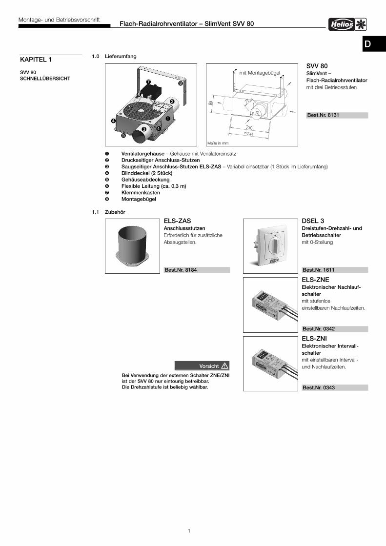
D1.0 Lieferumfang
� Ventilatorgehäuse – Gehäuse mit Ventilatoreinsatz� Druckseitiger Anschluss-Stutzen� Saugseitiger Anschluss-Stutzen ELS-ZAS – Variabel einsetzbar (1 Stück im Lieferumfang)� Blinddeckel (2 Stück)� Gehäuseabdeckung Flexible Leitung (ca. 0,3 m) Klemmenkasten� Montagebügel
1.1 Zubehör
KAPITEL 1
SVV 80SCHNELLÜBERSICHT
�
�
��
DSEL 3Dreistufen-Drehzahl- undBetriebsschaltermit 0-Stellung
Best.Nr. 1611
ELS-ZASAnschlussstutzenErforderlich für zusätzlicheAbsaugstellen.
Best.Nr. 8184
ELS-ZNEElektronischer Nachlauf-schaltermit stufenloseinstellbaren Nachlaufzeiten.
Best.Nr. 0342
ELS-ZNIElektronischer Intervall-schaltermit einstellbaren Intervall-und Nachlaufzeiten.
Best.Nr. 0343
SVV 80SlimVent –Flach-Radialrohrventilatormit drei Betriebsstufen
Best.Nr. 8131
Maße in mm
mit Montagebügel
�
�
Bei Verwendung der externen Schalter ZNE/ZNIist der SVV 80 nur eintourig betreibbar.Die Drehzahlstufe ist beliebig wählbar.
Vorsicht �
�

2
Flach-Radialrohrventilator – SlimVent SVV 80Montage- und Betriebsvorschrift
2.0 Wichtige InformationenZur Sicherstellung einer einwandfreien Funktion und zur eigenen Sicherheit sind alle nachstehenden Vorschriften genaudurchzulesen und zu beachten. Der Elektroanschluss muss bis zur Endmontage allpolig vom Netz getrennt werden!Die MBV nach der Endmontage dem Betreiber (Mieter/Eigentümer) aushändigen.
2.1 Warn- und SicherheitshinweiseNebenstehendes Symbol ist ein sicherheitstechnischer Warnhinweis. Alle Sicherheitsvorschriften bzw. Symbolemüssen unbedingt beachtet werden, damit jegliche Gefahrensituation vermieden wird.
2.2 Garantieansprüche – HaftungsausschlussWenn die vorhergehenden Ausführungen nicht beachtet werden, entfällt unsere Gewährleistung und Behandlung aufKulanz. Gleiches gilt für Haftungsansprüche an den Hersteller.Der Gebrauch von Zubehörteilen, die nicht von Helios empfohlen oder angeboten werden, ist nicht statthaft. Eventuellauftretende Schäden unterliegen nicht der Gewährleistung.
2.3 Vorschriften – RichtlinienBei ordnungsgemäßer Installation und bestimmungsgemäßem Betrieb entspricht das Gerät den zum Zeitpunkt seinerHerstellung gültigen Vorschriften und CE-Richtlinien.
2.4 SendungsannahmeDie Sendung sofort bei Anlieferung auf Beschädigungen und Typenrichtigkeit prüfen. Falls Schäden vorliegen umge-hend Schadensmeldung unter Hinzuziehung des Transportunternehmens veranlassen.Bei nicht fristgerechter Reklamation gehen evtl. Ansprüche verloren.
2.5 EinlagerungBei Einlagerung über einen längeren Zeitraum sind zur Verhinderung schädlicher Einwirkungen folgende Maßnahmenzu treffen:Versiegelung der blanken Teile mit Korrosionsschutz, Schutz des Motors durch trockene, luft- und staubdichte Ver-packung (Kunststoffbeutel mit Trockenmittel und Feuchtigkeitsindikatoren). Der Lagerort muss erschütterungsfrei, was-sergeschützt und frei von übermäßigen Temperaturschwankungen sein.Bei mehrjähriger Lagerung bzw. Motorstillstand muss vor Inbetriebnahme eine Inspektion der Lager und gegebenen-falls ein Lageraustausch durchgeführt werden. Zusätzlich ist eine elektrische Prüfung nach VDE 0701 bzw. VDE 0530durchzuführen.Bei Weiterversand (vor allem über längere Distanzen) ist zu prüfen, ob die Verpackung für Transportart und -weg ge-eignet ist. Schäden, deren Ursache in unsachgemäßem Transport, Einlagerung oder Inbetriebnahme liegen, sind nach-weisbar und unterliegen nicht der Gewährleistung.
2.6 EinsatzbereichDie SlimVent Ventilatoren sind für den vielseitigen Einsatz im Neubau und bei der Renovierung konzipiert. Im robustenGehäuse aus schlagfestem Kunststoff eignet sich das Gerät für den Industrie-, Gewerbe- und Wohnbereich zur Lüf-tung von Feuchträumen, Toiletten u.a.m. Der leistungsstarke Energiesparmotor und die ultraSilence® Technologie fürflüsterleisen Betrieb ermöglichen eine universelle Verwendung.Zur Lüftung mehrerer Räume können durch Abnehmen der Blinddeckel ein oder zwei weitere Ansaugstutzen (Zubehör,siehe Seite 2) in das Gehäuse eingesetzt werden. Die SlimVent Ventilatoren verfügen serienmäßig über drei Leistungs-stufen 110, 65 und 35 m3/h.Bei der Installation direkt im Rohrverlauf z.B. in abgehängten Decken, findet das Gerät mit 98 mm Einbautiefe überallPlatz – egal, wie eng es zugeht.Kugellager, die für 40.000 Betriebsstunden ausgelegt und gefettet sind, garantieren einen leichten, geräuscharmen Laufund erlauben den Einbau in jeder Lage. Ein bestimmungsfremder Einsatz ist nicht zulässig!
2.7 LeistungsdatenZum Erreichen der vorgesehenen Leistung ist ein ordnungsgemäßer Einbau, korrekt ausgeführte Leitungsführung undausreichende Zuluftversorgung sicherzustellen.Bei Betrieb von schornsteinabhängigen Feuerstellen im entlüfteten Raum muss diesen bei allen Betriebsbedingungenausreichend Zuluft zugeführt werden (Rückfrage beim Schornsteinfeger).Abweichende Ausführungen und ungünstige Einbau- und Betriebsbedingungen können zu einer Reduzierung der För-derleistung führen.Die Geräuschangaben erfolgen als A-bewerteter Schalldruckpegel.
2.8 Allgemeine HinweiseZuluftführung: Jeder zu entlüftende Raum, muss eine unverschließbare Nachströmöffnung von 150 cm² freien Quer-schnitts haben.
2.9 SicherheitWartungs- und Installationsarbeiten dürfen nur von einer autorisierten Elektrofachkraft vorgenommen wer-
den.- Die Ventilatoren dürfen nur mit der auf dem Typenschild angegebenen Nennspannung betrieben werden.- Technische Daten auf Typenschild unbedingt beachten.- Die auf dem Typenschild angegebene Schutzart gilt nur bei bestimmungsgemäßen Einbau gemäß dieserMontage- und Betriebsvorschrift.
KAPITEL 2
ALLGEMEINE HINWEISE
�
HINWEIS �
WARNUNG �
D

3
Flach-Radialrohrventilator – SlimVent SVV 80Montage- und Betriebsvorschrift
3.0 MontageEntnehmen Sie die Liefereinheit erst unmittelbar vor dem Einbau aus dem Karton, um mögliche Beschädigungen undVerschmutzungen beim Transport sowie auf der Baustelle zu vermeiden.
3.1 Vorbereitung zur Montage: Absaugstutzen montieren
Vor allen Wartungs- und Installationsarbeiten und vor Öffnen des Gerätes, ist das Gerät allpoligvom Netz zu trennen!
Bis zu drei Absaugstutzen können montiert werden (siehe Abb 4).
KAPITEL 3
MONTAGE
Abb.4
WARNUNG �
Stutzenposition GesamtNr. 1 Nr. 2 Nr. 3 Leistung
V· m3/h V· m3/h V· m3/h V· m3/h
35 45 45 125
65 zu 60 125
zu 45 75 120
50 60 zu 110*
110 zu zu 110
zu zu 110 110
zu 100 zu 100
Die Volumenleistung in Abhängigkeitder saugseitigen Stutzen-Anzahl undPosition.* Fördervolumen auf Stufe 1/2/335/65/110 m3/h
Abb.1
�
�
Abb.3
�
�
Absaugstutzen 90°links (im Bild) bzw. rechts montieren
Absaugstutzen �unten montieren
Nr. 2
Nr. 1
Nr. 3
Abb.2
�
�
1. Blinddeckel �seitlich entfernen
2. Blinddeckel� un-ten einsetzen
�
D
4
Flach-Radialrohrventilator – SlimVent SVV 80Montage- und Betriebsvorschrift
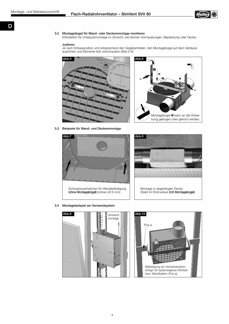
3.2 Montagebügel für Wand- oder Deckenmontage montierenErforderlich für Unterputzmontage im Schacht, bei dünnen Vormauerungen, Beplankung oder Decke.
JustierenJe nach Einbauposition und entsprechend den Gegebenheiten, den Montagebügel auf dem Gehäuseausrichten und Elemente fest verschrauben (Abb.5-6).
3.3 Beispiele für Wand- und Deckenmontage
3.4 Montagebeispiel am Vorwandsystem
90°
Abb.9
Abb.6
Montagebügel � kann an der Einker-bung gebogen oder gekürzt werden.
Abb.10
Pos a.
Abb.5
Befestigung am Vorwandsystemerfolgt mit systemeigenen Winkelnbzw. Wandhaltern (Pos a).
Vorwand-montage
Abb.7
Schraubenaufnahmen für Wandbefestigung((oohhnnee MMoonnttaaggeebbüüggeell)) bohren (Ø 6 mm)
Abb.8
Montage in abgehängter Decke.Direkt im Rohrverlauf ((mmiitt MMoonnttaaggeebbüüggeell))
~
~
�
D
5
Flach-Radialrohrventilator – SlimVent SVV 80Montage- und Betriebsvorschrift
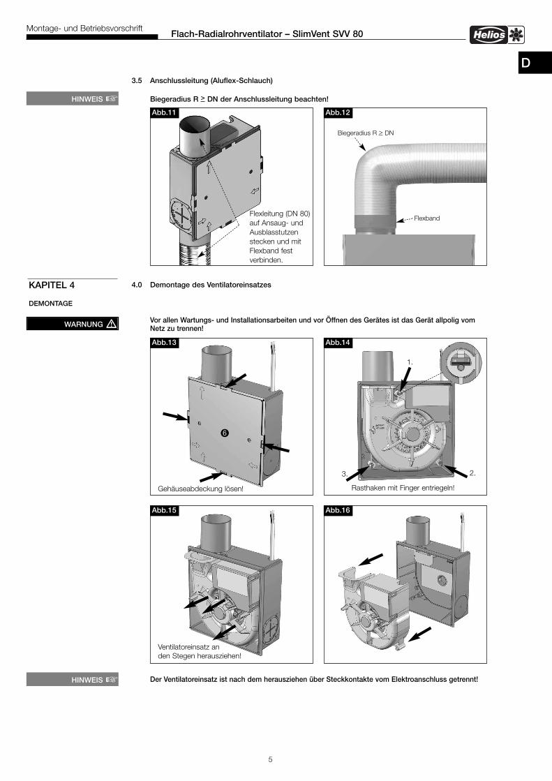
3.5 Anschlussleitung (Aluflex-Schlauch)
Biegeradius R > DN der Anschlussleitung beachten!
4.0 Demontage des Ventilatoreinsatzes
Vor allen Wartungs- und Installationsarbeiten und vor Öffnen des Gerätes ist das Gerät allpolig vomNetz zu trennen!
Der Ventilatoreinsatz ist nach dem herausziehen über Steckkontakte vom Elektroanschluss getrennt!
KAPITEL 4
DEMONTAGE
Abb.13
Abb.15
Abb.14
1.
Gehäuseabdeckung lösen! Rasthaken mit Finger entriegeln!
Abb.16
Ventilatoreinsatz an den Stegen herausziehen!
2.3.
WARNUNG �
HINWEIS �Abb.11
Flexleitung (DN 80) auf Ansaug- undAusblasstutzenstecken und mitFlexband fest verbinden.
Abb.12
Biegeradius R > DN
Flexband
HINWEIS �
D
6
Flach-Radialrohrventilator – SlimVent SVV 80Montage- und Betriebsvorschrift
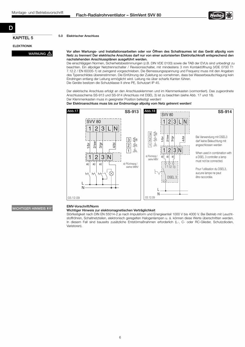
5.0 Elektrischer Anschluss
Vor allen Wartungs- und Installationsarbeiten oder vor Öffnen des Schaltraumes ist das Gerät allpolig vom Netz zu trennen! Der elektrische Anschluss darf nur von einer autorisierten Elektrofachkraft entsprechend den nachstehenden Anschlussplänen ausgeführt werden.Die einschlägigen Normen, Sicher heitsbestimmungen (z.B. DIN VDE 0100) sowie die TAB der EVUs sind unbedingt zubeachten. Ein allpoliger Netztrennschalter / Revisionsschalter, mit mindestens 3 mm Kontaktöffnung (VDE 0700 T1 7.12.2 / EN 60335-1) ist zwingend vorgeschrieben. Die Bemessungsspannung und Frequenz muss mit den Angaben des Typenschildes übereinstimmen. Die Einführung der Zuleitung so vornehmen, dass bei Wasserbeaufschlagung kein Eindringen entlang der Lei tung ermöglicht wird. Leitung nie über scharfe Kanten führen. Die Geräte besitzen die Schutzklasse II ohne PE, Schutzart IP 45.
Der elektrische Anschluss erfolgt an den Anschlussklemmen und im Klemmenkasten (vormontiert). Das zugeordneteAnschlussschema SS-913 und SS-914 (Anschluss mit DSEL 3) ist zu beachten (siehe Abb. 17 und 18).Der Klemmenkasten muss in geeigneter Position befestigt werden!Der Elektroanschluss muss bis zur Endmontage allpolig vom Netz getrennt werden!
EMV-Vorschrift/NormWichtiger Hinweis zur elektromagnetischen VerträglichkeitStörfestigkeit nach DIN EN 55014-2 je nach Impulsform und Energieanteil 1000 V bis 4000 V. Bei Betrieb mit Leucht-stoffröhren, Schaltnetzteilen, elektronisch geregelten Halogenlampen u. ä. können diese Werte überschritten werden.In diesem Fall sind bauseits zusätzliche Entstörmaßnahmen erforderlich (L-, C- oder RC-Glieder, Schutzdioden,Varistoren).
KAPITEL 5
ELEKTRONIK
WARNUNG �
WiCHTIGER HINWEIS �
85063 002 SS-913 03.12.09
1 2 3 L N
NL
SVV 80
a) a) Rückspg.!siehe MBV
a) a)
321
1 2 3 N
1/br
2/sw
3/gr
4/b l
SS-913Abb.17
85064 001 SS-914 03.12.09
1 2 3 L N
NL
SVV 80
a) Rückspg.!siehe MBV
321
1 2 3 N
Bei Verwendung mit DSEL3darf keine Beleuchtung mitangeschlossen werden
When used in combination witha DSEL 3 controller a lampmust not be connected.
Pour l'utilisation du DSEL3,aucune lampe ne peutêtre raccordée.DSEL 3
32
L
1
a) a) a)
1/b
r
2/s
w
3/g
r
4/b
l
SS-914Abb.18
D

7
Flach-Radialrohrventilator – SlimVent SVV 80Montage- und Betriebsvorschrift
Notizen:
D
8
Helios VentilatorenINSTALLATION AND OPERATING INSTRUCTIONS NO. 86134
Contents
CHAPTER 1. SLIMVENT SVV 80 QUICK OVERVIEW page 21.0 Scope of delivery . . . . . . . . . . . . . . . . . . . . . . . . . . . . . . . . . . . . . . . . . . . . . . . . . . . . . . . . . . . . . . . . . . . . . page 21.1 Accessory . . . . . . . . . . . . . . . . . . . . . . . . . . . . . . . . . . . . . . . . . . . . . . . . . . . . . . . . . . . . . . . . . . . . . . . . . . . page 2
CHAPTER 2. GENERAL INSTALLATION AND OPERATING INSTRUCTIONS . . . . . . . . . . . . . . . . . . . . . . . . . . . .page 3 2.0 Important information . . . . . . . . . . . . . . . . . . . . . . . . . . . . . . . . . . . . . . . . . . . . . . . . . . . . . . . . . . . . . . . . . . .page 32.1 Warning and safety instructions . . . . . . . . . . . . . . . . . . . . . . . . . . . . . . . . . . . . . . . . . . . . . . . . . . . . . . . . . . . .page 32.2 Warranty - Exclusion of liability . . . . . . . . . . . . . . . . . . . . . . . . . . . . . . . . . . . . . . . . . . . . . . . . . . . . . . . . . . . .page 32.3 Certificates . . . . . . . . . . . . . . . . . . . . . . . . . . . . . . . . . . . . . . . . . . . . . . . . . . . . . . . . . . . . . . . . . . . . . . . . . . .page 32.4 Receipt . . . . . . . . . . . . . . . . . . . . . . . . . . . . . . . . . . . . . . . . . . . . . . . . . . . . . . . . . . . . . . . . . . . . . . . . . . . . . .page 32.5 Storage . . . . . . . . . . . . . . . . . . . . . . . . . . . . . . . . . . . . . . . . . . . . . . . . . . . . . . . . . . . . . . . . . . . . . . . . . . . . . .page 32.6 Application/Operation . . . . . . . . . . . . . . . . . . . . . . . . . . . . . . . . . . . . . . . . . . . . . . . . . . . . . . . . . . . . . . . . . . .page 32.7 Performance . . . . . . . . . . . . . . . . . . . . . . . . . . . . . . . . . . . . . . . . . . . . . . . . . . . . . . . . . . . . . . . . . . . . . . . . . .page 32.8 Fire protection . . . . . . . . . . . . . . . . . . . . . . . . . . . . . . . . . . . . . . . . . . . . . . . . . . . . . . . . . . . . . . . . . . . . . . . . .page 32.9 General information . . . . . . . . . . . . . . . . . . . . . . . . . . . . . . . . . . . . . . . . . . . . . . . . . . . . . . . . . . . . . . . . . . . . .page 3
CHAPTER 3. INSTALLATION . . . . . . . . . . . . . . . . . . . . . . . . . . . . . . . . . . . . . . . . . . . . . . . . . . . . . . . . . . . . . . . . . page 43.0 Installation . . . . . . . . . . . . . . . . . . . . . . . . . . . . . . . . . . . . . . . . . . . . . . . . . . . . . . . . . . . . . . . . . . . . . . . . . . . page 43.1 Preparation for the installation: Install extraction spigot . . . . . . . . . . . . . . . . . . . . . . . . . . . . . . . . . . . . . . . . . page 43.2 Assemble mounting holder for wall or ceiling installation . . . . . . . . . . . . . . . . . . . . . . . . . . . . . . . . . . . . . . . . page 53.3 Examples of wall and ceiling installation . . . . . . . . . . . . . . . . . . . . . . . . . . . . . . . . . . . . . . . . . . . . . . . . . . . . . page 53.4 Installation example at the plasterboard system . . . . . . . . . . . . . . . . . . . . . . . . . . . . . . . . . . . . . . . . . . . . . . . page 53.5 Connecting duct (aluflex-ducting) . . . . . . . . . . . . . . . . . . . . . . . . . . . . . . . . . . . . . . . . . . . . . . . . . . . . . . . . . . page 6
CHAPTER 4. DISASSEMBLY . . . . . . . . . . . . . . . . . . . . . . . . . . . . . . . . . . . . . . . . . . . . . . . . . . . . . . . . . . . . . . . . page 64.0 Disassembly fan unit . . . . . . . . . . . . . . . . . . . . . . . . . . . . . . . . . . . . . . . . . . . . . . . . . . . . . . . . . . . . . . . . . . . page 6
CHAPTER 5. ELECTRONIC . . . . . . . . . . . . . . . . . . . . . . . . . . . . . . . . . . . . . . . . . . . . . . . . . . . . . . . . . . . . . . . . . . page 75.0 Electrical connection . . . . . . . . . . . . . . . . . . . . . . . . . . . . . . . . . . . . . . . . . . . . . . . . . . . . . . . . . . . . . . . . . . . page 7
Correct Disposal of This Product (Waste Electrical & Electronic Equipment)(Applicable in the European Union and other European countries with separate collection systems)This marking shown on the product or its Operation and Installation Instruction, indicates that it should not be disposed with other householdwastes at the end of its working life. To prevent possible harm to the environment or human health from uncontrolled waste disposal, pleaseseparate this from other types of wastes and recycle it responsibly to promote the sustainable reuse of material resources.Household users should contact either the retailer where they purchased this product, or their local government office, for details of whereand how they can take this item for environmentally safe recycling.Business users should contact their supplier and check the terms and conditions of the purchase contract.This product should not be mixed with other commercial wastes for disposal.
ENGLISH
9
Slim centrifugal fan box – SVV 80Installation and Operating Instructions
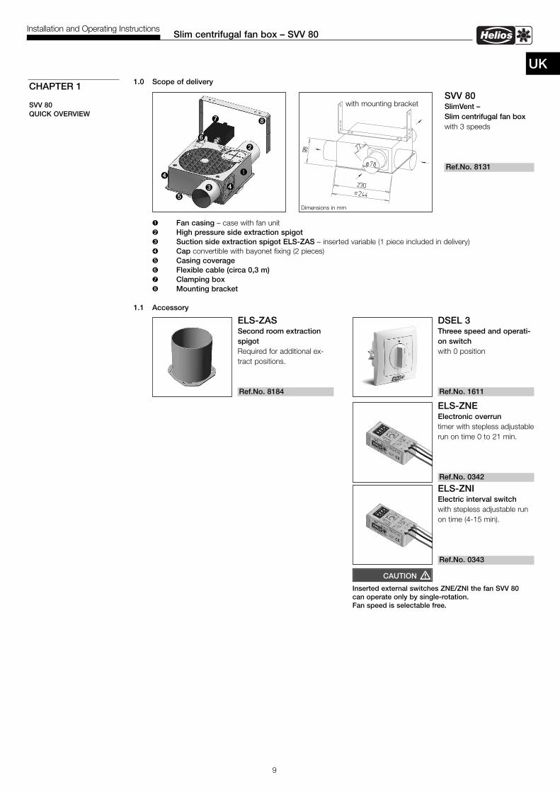
UK1.0 Scope of delivery
� Fan casing – case with fan unit � High pressure side extraction spigot � Suction side extraction spigot ELS-ZAS – inserted variable (1 piece included in delivery)� Cap convertible with bayonet fixing (2 pieces)� Casing coverage Flexible cable (circa 0,3 m) Clamping box� Mounting bracket
1.1 Accessory
CHAPTER 1
SVV 80 QUICK OVERVIEW
�
�
��
DSEL 3Threee speed and operati-on switch with 0 position
Ref.No. 1611
ELS-ZASSecond room extractionspigotRequired for additional ex-tract positions.
Ref.No. 8184
SVV 80SlimVent – Slim centrifugal fan boxwith 3 speeds
Ref.No. 8131
Dimensions in mm
with mounting bracket
�
�
�
ELS-ZNEElectronic overruntimer with stepless adjustablerun on time 0 to 21 min.
Ref.No. 0342
ELS-ZNIElectric interval switchwith stepless adjustable runon time (4-15 min).
Ref.No. 0343
Inserted external switches ZNE/ZNI the fan SVV 80can operate only by single-rotation.Fan speed is selectable free.
CAUTION �
10
Slim centrifugal fan box – SVV 80Installation and Operating Instructions
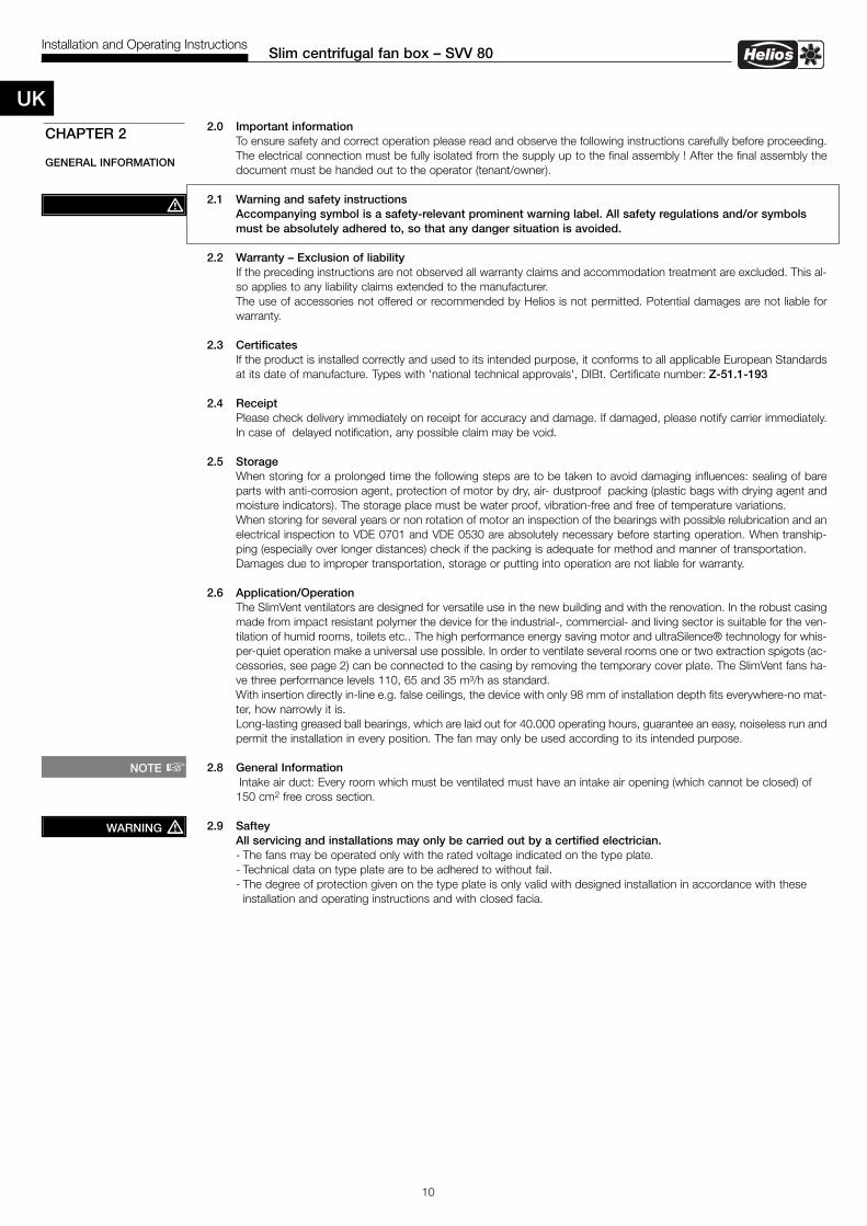
2.0 Important informationTo ensure safety and correct operation please read and observe the following instructions carefully before proceeding.The electrical connection must be fully isolated from the supply up to the final assembly ! After the final assembly thedocument must be handed out to the operator (tenant/owner).
2.1 Warning and safety instructions Accompanying symbol is a safety-relevant prominent warning label. All safety regulations and/or symbols must be absolutely adhered to, so that any danger situation is avoided.
2.2 Warranty – Exclusion of liabilityIf the preceding instructions are not observed all warranty claims and accommodation treatment are excluded. This al-so applies to any liability claims extended to the manufacturer.The use of accessories not offered or recommended by Helios is not permitted. Potential damages are not liable forwarranty.
2.3 CertificatesIf the product is installed correctly and used to its intended purpose, it conforms to all applicable European Standardsat its date of manufacture. Types with 'national technical approvals', DIBt. Certificate number: Z-51.1-193
2.4 ReceiptPlease check delivery immediately on receipt for accuracy and damage. If damaged, please notify carrier immediately.In case of delayed notification, any possible claim may be void.
2.5 StorageWhen storing for a prolonged time the following steps are to be taken to avoid damaging influences: sealing of bareparts with anti-corrosion agent, protection of motor by dry, air- dustproof packing (plastic bags with drying agent andmoisture indicators). The storage place must be water proof, vibration-free and free of temperature variations.When storing for several years or non rotation of motor an inspection of the bearings with possible relubrication and anelectrical inspection to VDE 0701 and VDE 0530 are absolutely necessary before starting operation. When tranship-ping (especially over longer distances) check if the packing is adequate for method and manner of transportation.Damages due to improper transportation, storage or putting into operation are not liable for warranty.
2.6 Application/OperationThe SlimVent ventilators are designed for versatile use in the new building and with the renovation. In the robust casingmade from impact resistant polymer the device for the industrial-, commercial- and living sector is suitable for the ven-tilation of humid rooms, toilets etc.. The high performance energy saving motor and ultraSilence® technology for whis-per-quiet operation make a universal use possible. In order to ventilate several rooms one or two extraction spigots (ac-cessories, see page 2) can be connected to the casing by removing the temporary cover plate. The SlimVent fans ha-ve three performance levels 110, 65 and 35 m³/h as standard.With insertion directly in-line e.g. false ceilings, the device with only 98 mm of installation depth fits everywhere-no mat-ter, how narrowly it is.Long-lasting greased ball bearings, which are laid out for 40.000 operating hours, guarantee an easy, noiseless run andpermit the installation in every position. The fan may only be used according to its intended purpose.
2.8 General InformationIntake air duct: Every room which must be ventilated must have an intake air opening (which cannot be closed) of 150 cm2 free cross section.
2.9 SafteyAll servicing and installations may only be carried out by a certified electrician.- The fans may be operated only with the rated voltage indicated on the type plate.- Technical data on type plate are to be adhered to without fail.- The degree of protection given on the type plate is only valid with designed installation in accordance with these installation and operating instructions and with closed facia.
CHAPTER 2
GENERAL INFORMATION
�
NOTE �
WARNING �
UK
11
Slim centrifugal fan box – SVV 80Installation and Operating Instructions
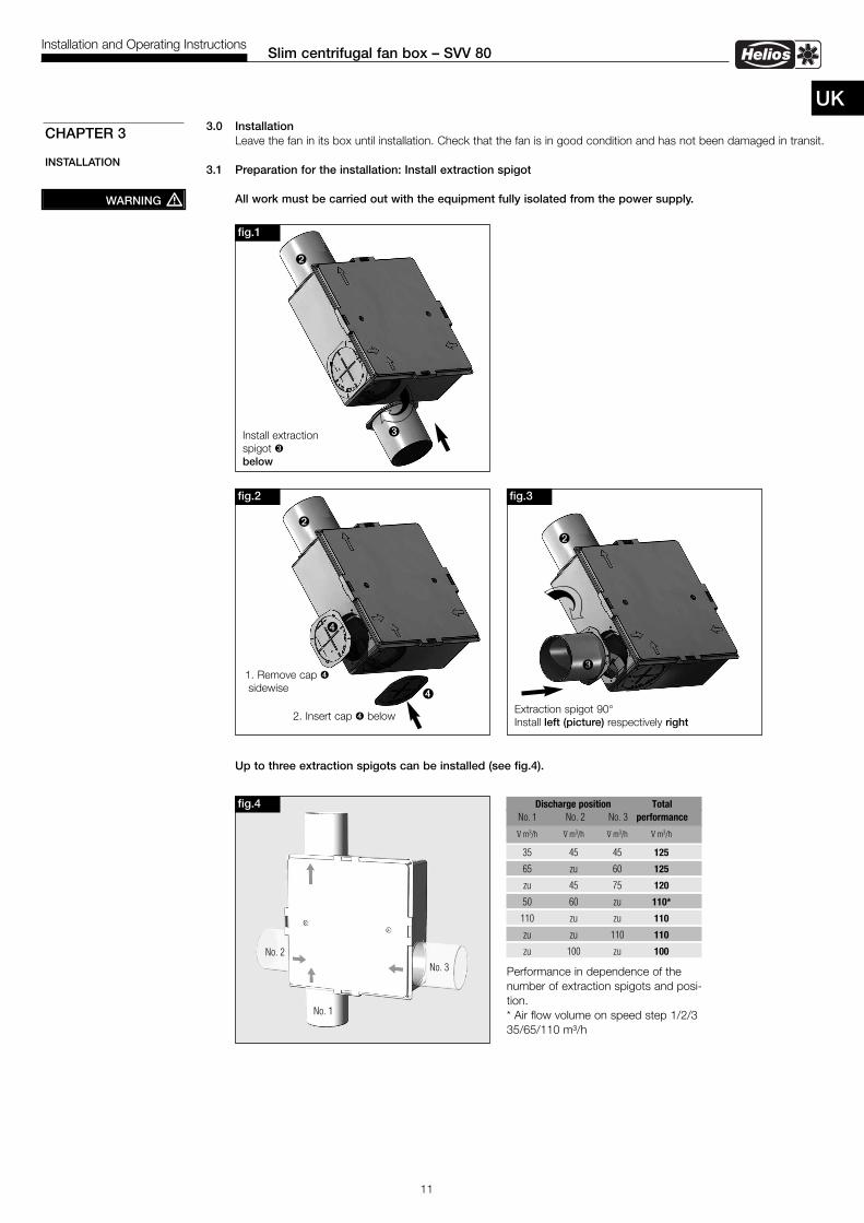
UK3.0 Installation
Leave the fan in its box until installation. Check that the fan is in good condition and has not been damaged in transit.
3.1 Preparation for the installation: Install extraction spigot
All work must be carried out with the equipment fully isolated from the power supply.
Up to three extraction spigots can be installed (see fig.4).
CHAPTER 3
INSTALLATION
fig.4
WARNING �
Discharge position TotalNo. 1 No. 2 No. 3 performance
V· m3/h V· m3/h V· m3/h V· m3/h
35 45 45 125
65 zu 60 125
zu 45 75 120
50 60 zu 110*
110 zu zu 110
zu zu 110 110
zu 100 zu 100
Performance in dependence of thenumber of extraction spigots and posi-tion.* Air flow volume on speed step 1/2/335/65/110 m³/h
fig.1
�
�
fig.3
�
�
Extraction spigot 90°Install left (picture) respectively right
Install extraction spigot �below
No. 2
No. 1
No. 3
fig.2
�
�
1. Remove cap �sidewise
2. Insert cap � below
�
12
Slim centrifugal fan box – SVV 80Installation and Operating Instructions
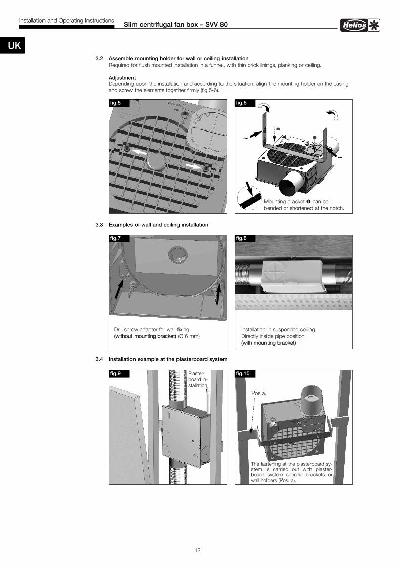
3.2 Assemble mounting holder for wall or ceiling installationRequired for flush mounted installation in a funnel, with thin brick linings, planking or ceiling.
AdjustmentDepending upon the installation and according to the situation, align the mounting holder on the casingand screw the elements together firmly (fig.5-6).
3.3 Examples of wall and ceiling installation
3.4 Installation example at the plasterboard system
90°
fig.9
fig.6
Mounting bracket � can be bended or shortened at the notch.
fig.10
Pos a.
fig.5
The fastening at the plasterboard sy-stem is carried out with plaster-board system specific brackets orwall holders (Pos. a).
Plaster-board in-stallation
fig.7
Drill screw adapter for wall fixing((wwiitthhoouutt mmoouunnttiinngg bbrraacckkeett)) (Ø 6 mm)
fig.8
Installation in suspended ceiling.Directly inside pipe position ((wwiitthh mmoouunnttiinngg bbrraacckkeett))
~
~
UK

13
Slim centrifugal fan box – SVV 80Installation and Operating Instructions
Notice:
UK
14
Helios VentilatorenNOTICE DE MONTAGE ET D’UTILISATION N° 86134
Sommaire
CHAPITRE 1. PRESENTATION DU SLIMVENT SVV 80 . . . . . . . . . . . . . . . . . . . . . . . . . . . . . . . . . . . . . . . . . . . Page 21.0 Kit d’installation . . . . . . . . . . . . . . . . . . . . . . . . . . . . . . . . . . . . . . . . . . . . . . . . . . . . . . . . . . . . . . . . . . . . . . . Page 21.1 Accessoires . . . . . . . . . . . . . . . . . . . . . . . . . . . . . . . . . . . . . . . . . . . . . . . . . . . . . . . . . . . . . . . . . . . . . . . . . Page 2
CHAPITRE 2. INFORMATIONS GENERALES . . . . . . . . . . . . . . . . . . . . . . . . . . . . . . . . . . . . . . . . . . . . . . . . . . . . Page 3 2.0 Informations importantes . . . . . . . . . . . . . . . . . . . . . . . . . . . . . . . . . . . . . . . . . . . . . . . . . . . . . . . . . . . . . . . . Page 32.1 Précautions et consignes de sécurité . . . . . . . . . . . . . . . . . . . . . . . . . . . . . . . . . . . . . . . . . . . . . . . . . . . . . . . Page 32.2 Demande de garantie – Réserves du constructeur . . . . . . . . . . . . . . . . . . . . . . . . . . . . . . . . . . . . . . . . . . . . . Page 32.3 Réglementation – Normes . . . . . . . . . . . . . . . . . . . . . . . . . . . . . . . . . . . . . . . . . . . . . . . . . . . . . . . . . . . . . . . Page 32.4 Réception de l’envoi . . . . . . . . . . . . . . . . . . . . . . . . . . . . . . . . . . . . . . . . . . . . . . . . . . . . . . . . . . . . . . . . . . . Page 32.5 Stockage . . . . . . . . . . . . . . . . . . . . . . . . . . . . . . . . . . . . . . . . . . . . . . . . . . . . . . . . . . . . . . . . . . . . . . . . . . . . Page 32.6 Domaine d’utilisation . . . . . . . . . . . . . . . . . . . . . . . . . . . . . . . . . . . . . . . . . . . . . . . . . . . . . . . . . . . . . . . . . . . Page 32.7 Caractéristiques techniques . . . . . . . . . . . . . . . . . . . . . . . . . . . . . . . . . . . . . . . . . . . . . . . . . . . . . . . . . . . . . . Page 32.8 Généralités . . . . . . . . . . . . . . . . . . . . . . . . . . . . . . . . . . . . . . . . . . . . . . . . . . . . . . . . . . . . . . . . . . . . . . . . . . . Page 32.9 Sécurité . . . . . . . . . . . . . . . . . . . . . . . . . . . . . . . . . . . . . . . . . . . . . . . . . . . . . . . . . . . . . . . . . . . . . . . . . . . . Page 3
CHAPITRE 3. MONTAGE . . . . . . . . . . . . . . . . . . . . . . . . . . . . . . . . . . . . . . . . . . . . . . . . . . . . . . . . . . . . . . . . . . . Page 43.0 Montage . . . . . . . . . . . . . . . . . . . . . . . . . . . . . . . . . . . . . . . . . . . . . . . . . . . . . . . . . . . . . . . . . . . . . . . . . . . . Page 43.1 Montage des piquages d’aspiration . . . . . . . . . . . . . . . . . . . . . . . . . . . . . . . . . . . . . . . . . . . . . . . . . . . . . . . . Page 43.2 Support de montage pour pose murale ou plafonnière . . . . . . . . . . . . . . . . . . . . . . . . . . . . . . . . . . . . . . . . . Page 53.3 Exemples de montage au mur et au plafond . . . . . . . . . . . . . . . . . . . . . . . . . . . . . . . . . . . . . . . . . . . . . . . . . Page 53.4 Montage en gaine technique . . . . . . . . . . . . . . . . . . . . . . . . . . . . . . . . . . . . . . . . . . . . . . . . . . . . . . . . . . . . . Page 53.5 Raccordement (tube flexible alu) . . . . . . . . . . . . . . . . . . . . . . . . . . . . . . . . . . . . . . . . . . . . . . . . . . . . . . . . . . Page 6
CHAPITRE 4. DEMONTAGE . . . . . . . . . . . . . . . . . . . . . . . . . . . . . . . . . . . . . . . . . . . . . . . . . . . . . . . . . . . . . . . . . Page 64.0 Démontage de l’unité de ventilation . . . . . . . . . . . . . . . . . . . . . . . . . . . . . . . . . . . . . . . . . . . . . . . . . . . . . . . . Page 6
CHAPITRE 5. ELECTRONIQUE . . . . . . . . . . . . . . . . . . . . . . . . . . . . . . . . . . . . . . . . . . . . . . . . . . . . . . . . . . . . . . . Page 75.0 Raccordement électrique . . . . . . . . . . . . . . . . . . . . . . . . . . . . . . . . . . . . . . . . . . . . . . . . . . . . . . . . . . . . . . . . Page 7
Comment éliminer ce produit (déchets d’équipements électriques et électroniques)Ce symbole sur le produit ou sa documentation indique qu’il ne doit pas être éliminé en fin de vie avec les autres déchets ménagers. L’élimi-nation incontrôlée des déchets pouvant porter préjudice à l’environnement ou à la santé humaine, veuillez le séparer des autres types de dé-chets et le recycler de façon responsable. Vous favoriserez ainsi la réutilisation durable des ressources matérielles.Les particuliers sont invités à contacter le distributeur leur ayant vendu le produit ou à se renseigner auprès de leur mairie pour savoir où etcomment ils peuvent se débarrasser de ce produit afin qu’il soit recyclé en respectant l’environnement.Les entreprises sont invitées à contacter leurs fournisseurs et à consulter les conditions de leur contrat de vente. Ce produit ne doit pas êtreéliminé avec les autres déchets commerciaux.
FRANÇAIS
15
Groupe de ventilation extra-plat – SlimVent SVV 80Notice de montage et d’utilisation
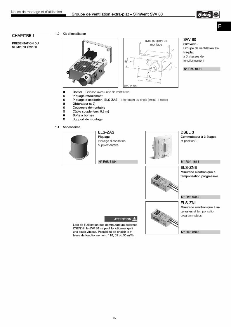
F1.0 Kit d’installation
� Boîtier – Caisson avec unité de ventilation � Piquage refoulement � Piquage d’aspiration ELS-ZAS – orientation au choix (inclus 1 pièce)� Obturateur (x 2)� Couvercle démontable Câble souple (env. 0,3 m) Boîte à bornes � Support de montage
1.1 Accessoires
CHAPITRE 1
PRESENTATION DU SLIMVENT SVV 80
�
�
��
DSEL 3Commutateur à 3 étages et position 0
N° Réf. 1611
ELS-ZASPiquagePiquage d’aspiration supplémentaire
N° Réf. 8184
ELS-ZNEMinuterie électronique àtemporisation progressive.
N° Réf. 0342
ELS-ZNIMinuterie électronique à in-tervalles et temporisationprogrammables
N° Réf. 0343
SVV 80SlimVent – Groupe de ventilation ex-tra-platà 3 vitesses defonctionnement
N° Réf. 8131
Dim. en mm
avec support demontage
�
�
Lors de l’utilisation des commutateurs externesZNE/ZNI, le SVV 80 ne peut fonctionner qu’àune seule vitesse. Possibilité de choisir la vi-tesse de fonctionnement: 110, 65 ou 35 m3/h.
ATTENTION �
�
16
2.0 Informations importantes Il est important de bien lire et respecter l’ensemble des prescriptions suivantes pour le bon fonctionnement de l’appa-reil et la sécurité des utilisateurs. L’alimentation électrique doit être maintenue hors tension jusqu’à la fin de l’ins-tallation ! Une fois le montage terminé, la notice de montage et d’installation doit être remise en mains propres à l’uti-lisateur (locataire/propriétaire).
2.1 Précautions et consignes de sécuritéLe symbole ci-contre indique une consigne de sécurité. Toutes les consignes de sécurité, ainsi que les symboles,doivent impérativement être respectés, afin d’éviter tout danger.
2.2 Demande de garantie – Réserves du constructeurEn cas de non-respect des indications suivantes, toute demande de remplacement ou de réparation à titre gratuit se-ra déclinée. Il en sera de même pour toute implication de responsabilité du fabricant.L’utilisation d’accessoires et d’équipements qui ne sont directement fournis ou conseillés par Helios n’est pas permi-se. Nous déclinons toute responsabilité en cas de défaut consécutif à leur utilisation.
2.3 Réglementation – NormesCet appareil est conforme aux directives CE en vigueur le jour de sa fabrication sous réserve d’une utilisation appropriée.
2.4 Réception de l’envoiDès réception, vérifier l’état et la conformité du matériel commandé. En cas d’avaries, des réserves doivent être portéessur le bordereau du transporteur. Elles doivent être précises, significatives, complètes et confirmées par lettre recom-mandée au transporteur. Attention le non respect de la procédure peut entraîner le rejet de la réclamation.
2.5 StockagePour un stockage de plus longue durée, se conformer aux instructions suivantes, pour éviter toutes détériorations pré-judiciables :Protéger les parties apparentes contre la corrosion. Protéger le moteur, grâce à un emballage sec, étanche à l’air et lapoussière (sac en matière synthétique contenant des sachets deshydrateurs et un indicateur d’humidité). Le matérielest à stocker dans un endroit abrité de l’eau, exempt de variations de températures et de vibrations.En cas de stockage sur plusieurs années entraînant une immobilisation du moteur, il faut effectuer un contrôle des rou-lements et éventuellement les changer, avant la mise en service. De plus, procéder à un contrôle électrique, selon lesdirectives VDE 0701 et VDE 0530.En cas de réexpédition (surtout sur de grandes distances), vérifier que l’emballage est bien approprié aux conditionsde transport. Les dommages dus à de mauvaises conditions de transport ou de stockage, à une utilisation anormalesont sujets à vérification et contrôle et entraînent la suppression de notre garantie.
2.6 Domaine d’utilisationLe ventilateur SlimVent SVV 80 est conçu pour répondre à de multiples besoins dans la construction neuve et dans larénovation. Grâce à son caisson robuste, en matière synthétique, l’appareil convient parfaitement pour la ventilation depièces humides, sanitaires etc. dans l’industrie, le tertiaire et l’habitat.Le moteur puissant à faible consommation d’énergie et la technologie UltraSilence ® permettent une utilisation univer-selle. Pour la ventilation de plusieurs pièces, un ou deux raccords d’aspiration supplémentaires (acc., voir page 2) peu-vent être montés sur le boîtier en lieu et place des obturateurs. Le SVV 80 est équipé de trois vitesses de fonctionne-ment de série: 110, 65 et 35 m3/h. Le ventilateur trouve place partout même dans les endroits les plus exigus. Grâce à sa faible épaisseur (98 mm), il peutpar exemple être monté en faux plafond, directement dans le réseau aéraulique. Des roulements à billes, conçus et graissés pour une durée de vie de 40.000 h, garantissent un fonctionnement silen-cieux et permettent un montage en toutes positions. Toute autre utilisation n’est pas autorisée.
2.7 Caractéristiques techniquesUn montage conforme aux règles de l’art, un réseau aéraulique correctement réalisé et une amenée d’air suffisantepermettent d’atteindre les performances prévues.En cas de présence d’un foyer avec conduit de fumée dans une pièce ventilée, veiller, en toutes conditions d’utilisa-tions, à amener une quantité d’air comburant suffisante (précisions supplémentaires à demander au ramoneur).Des réalisations non-conformes et/ou des conditions d’installation et de fonctionnement défavorables peuvent condui-re à une réduction des performances. Les données acoustiques sont indiquées en pression sonore pondérées en A.
2.8 GénéralitésAmenée d’air : chaque pièce à ventiler doit avoir une ouverture d’aération non obturable d’une section de 150 cm².
2.9 Sécurité– Les travaux d’entretien et d’installation ne peuvent être réalisés que par un électricien qualifié.- Respecter la tension d’alimentation nominale indiquée sur l’étiquette.- Respecter obligatoirement les caractéristiques techniques indiquées sur l’étiquette.- L’indice de protection indiqué sur l’étiquette n’est valable uniquement en cas d’installation conforme à cette notice de montage et d’utilisation.
CHAPITRE 2
INFORMATIONS GENERALES
�
CONSIGNE �
ATTENTION �
Groupe de ventilation extra-plat – SlimVent SVV 80Notice de montage et d’utilisation
F
17
Groupe de ventilation extra-plat – SlimVent SVV 80Notice de montage et d’utilisation
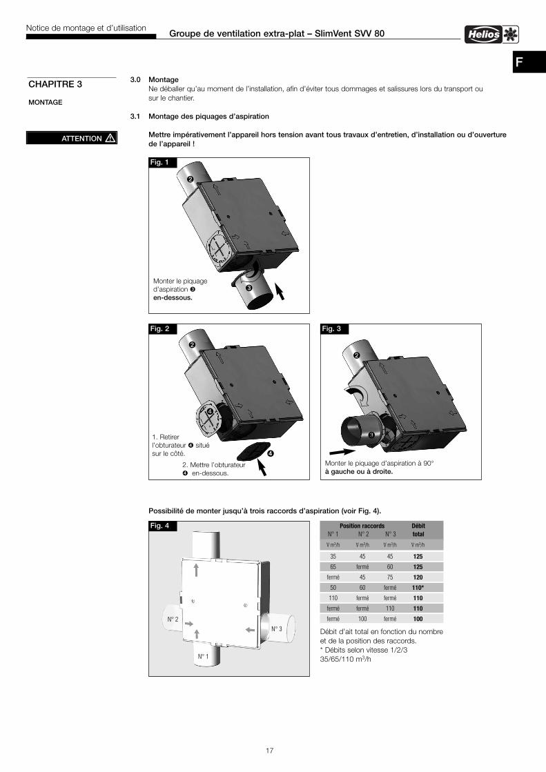
3.0 MontageNe déballer qu’au moment de l’installation, afin d’éviter tous dommages et salissures lors du transport ou sur le chantier.
3.1 Montage des piquages d’aspiration
Mettre impérativement l’appareil hors tension avant tous travaux d’entretien, d’installation ou d’ouverture de l’appareil !
Possibilité de monter jusqu’à trois raccords d’aspiration (voir Fig. 4).
CHAPITRE 3
MONTAGE
Fig. 4
ATTENTION �
Position raccords DébitN° 1 N° 2 N° 3 total
V· m3/h V· m3/h V· m3/h V· m3/h
35 45 45 125
65 fermé 60 125
fermé 45 75 120
50 60 fermé 110*
110 fermé fermé 110
fermé fermé 110 110
fermé 100 fermé 100
Débit d’ait total en fonction du nombreet de la position des raccords.* Débits selon vitesse 1/2/3 35/65/110 m3/h
Fig. 1
�
�
Fig. 3
�
�
Monter le piquage d’aspiration à 90°à gauche ou à droite.
Monter le piquage d’aspiration �en-dessous.
N° 2
N° 1
N° 3
Fig. 2
�
�
1. Retirer l’obturateur � situé sur le côté.
2. Mettre l’obturateur� en-dessous.
�
F
18
Groupe de ventilation extra-plat – SlimVent SVV 80Notice de montage et d’utilisation
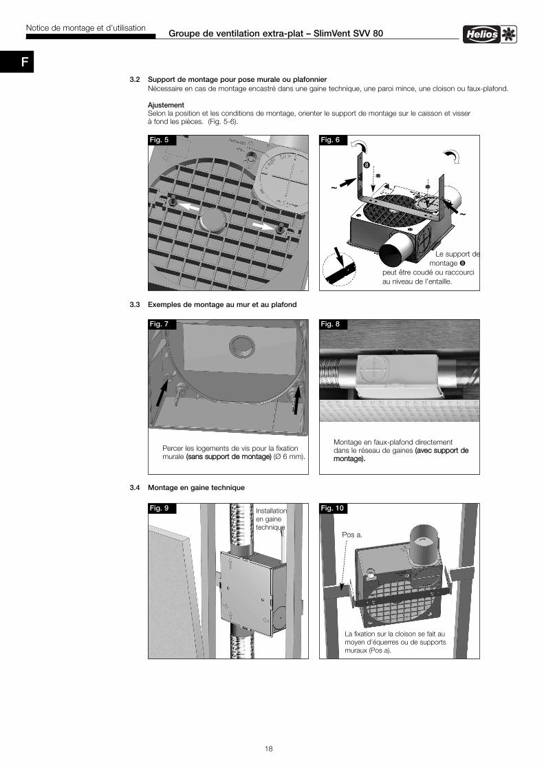
3.2 Support de montage pour pose murale ou plafonnierNécessaire en cas de montage encastré dans une gaine technique, une paroi mince, une cloison ou faux-plafond.
AjustementSelon la position et les conditions de montage, orienter le support de montage sur le caisson et visser à fond les pièces. (Fig. 5-6).
3.3 Exemples de montage au mur et au plafond
3.4 Montage en gaine technique
90°
Fig. 9
Fig. 6
Le support de montage �
peut être coudé ou raccourci au niveau de l’entaille.
Fig. 10
Pos a.
Fig. 5
La fixation sur la cloison se fait aumoyen d’équerres ou de supportsmuraux (Pos a).
Installation en gainetechnique
Fig. 7
Percer les logements de vis pour la fixationmurale ((ssaannss ssuuppppoorrtt ddee mmoonnttaaggee)) (Ø 6 mm).
Fig. 8
Montage en faux-plafond directement dans le réseau de gaines ((aavveecc ssuuppppoorrtt ddeemmoonnttaaggee))..
~
~
�
F
19
Groupe de ventilation extra-plat – SlimVent SVV 80Notice de montage et d’utilisation
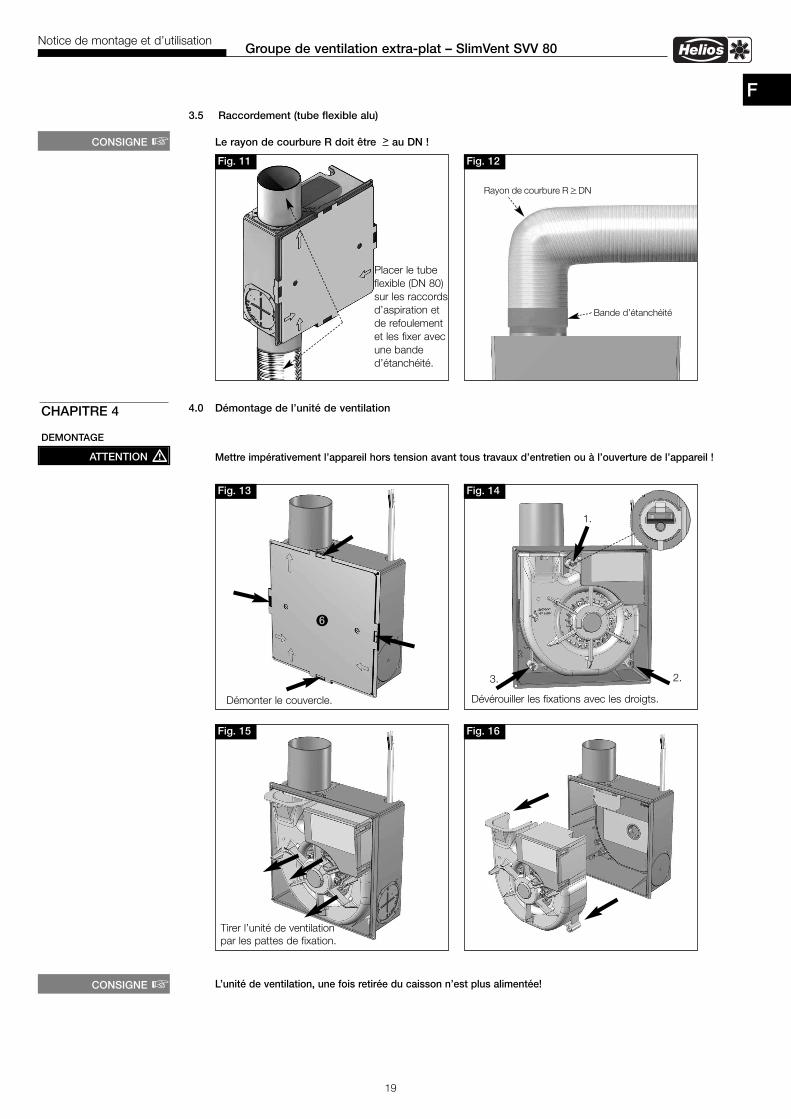
3.5 Raccordement (tube flexible alu)
Le rayon de courbure R doit être > au DN !
4.0 Démontage de l’unité de ventilation
Mettre impérativement l’appareil hors tension avant tous travaux d’entretien ou à l’ouverture de l’appareil !
L’unité de ventilation, une fois retirée du caisson n’est plus alimentée!
CHAPITRE 4
DEMONTAGE
Fig. 13
Fig. 15
Fig. 14
1.
Démonter le couvercle. Dévérouiller les fixations avec les droigts.
Fig. 16
Tirer l’unité de ventilationpar les pattes de fixation.
2.3.
ATTENTION �
CONSIGNE �Fig. 11
Placer le tubeflexible (DN 80)sur les raccordsd’aspiration et de refoulementet les fixer avec une bande d’étanchéité.
Fig. 12
Rayon de courbure R > DN
Bande d’étanchéité
CONSIGNE �
F
20
Groupe de ventilation extra-plat – SlimVent SVV 80Notice de montage et d’utilisation
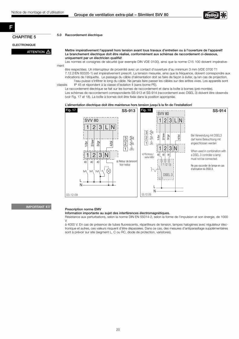
5.0 Raccordement électrique
Mettre impérativement l’appareil hors tension avant tous travaux d’entretien ou à l’ouverture de l’appareil! Le branchement électrique doit être réalisé, conformément aux schémas de raccordement ci-dessous, uniquement par un électricien qualifié! Les normes et consignes de sécurité (par exemple DIN VDE 0100), ainsi que la norme C15 100 doivent impérative-
mentêtre respectées. Un interrupteur de proximité avec un contact d’ouverture d’au minimum 3 mm (VDE 0700 T17.12.2/EN 60335-1) est impérativement prescrit. La tension mesurée, ainsi que la fréquence, doivent correspondre auxindications de l’étiquette. Le passage du câble d'alimentation doit se faire de façon à éviter, qu'en cas de projection,
l'eau puisse s'infiltrer le long du câble. Ne jamais faire passer les câbles sur des arêtes vives. Les appareils sontclassés IP 45 et répondent à la classe d’isolation II (sans borne PE).
Le raccordement électrique se fait sur les bornes de raccordement et dans la boîte à bornes (pré-montée). Les schémas de raccordement correspondants SS-913 et SS-914 (raccordement avec DSEL 3) doivent être observés(voir Fig. 17 et 18). La boîte à bornes doit être fixée dans la position appropriée.
L’alimentation électrique doit être maintenue hors tension jusqu’à la fin de l’installation!
Prescription norme EMVInformation importante au sujet des interférences électromagnétiques.Résistance aux perturbations, selon la norme DIN EN 55014-2, selon la forme de l’impulsion et son énergie, de 1000Và 4000 V. En cas de présence de tubes fluorescents, répartiteurs de tension, lampes halogènes avec régulateur élec-tronique et autres, ces valeurs risquent d’être dépassées. Dans ce cas, des mesures d’antiparasitage supplémentairessont à prévoir sur site (segment L, C ou RC, diode de protection, varistores).
CHAPITRE 5
ELECTRONIQUE
ATTENTION �
IMPORTANT �
85063 002 SS-913 03.12.09
1 2 3 L N
NL
SVV 80
a) a) Rückspg.!siehe MBV
a) a)
321
1 2 3 N
1/br
2/sw
3/gr
4/b l
SS-913Fig. 17
85064 001 SS-914 03.12.09
1 2 3 L N
NL
SVV 80
a) Rückspg.!siehe MBV
321
1 2 3 N
Bei Verwendung mit DSEL3darf keine Beleuchtung mitangeschlossen werden
When used in combination witha DSEL 3 controller a lampmust not be connected.
Pour l'utilisation du DSEL3,aucune lampe ne peutêtre raccordée.DSEL 3
32
L
1
a) a) a)1/b
r
2/s
w
3/g
r
4/b
l
SS-914Fig. 18
a) Retour de tension!Voir notice Ne pas raccorder de lampe en cas
d’utilisation du DSEL3.
F

21
Notation:
Groupe de ventilation extra-plat – SlimVent SVV 80Notice de montage et d’utilisation
F

Als Referenz am Gerät griffbereit aufbewahren! Druckschrift-Nr.Please keep this manual for reference with the unit! Print-No.:Conservez cette notice à proximité de l’apapreil! N° Réf. 86134/12.09
Service und InformationD HELIOS Ventilatoren GmbH & Co · Lupfenstraße 8 · 78056 VS-Schwenningen F HELIOS Ventilateurs · Le Carré des Aviateurs · 157 av. Charles Floquet · 93155 Le Blanc Mesnil CedexCH HELIOS Ventilatoren AG · Steinackerstraße 36 · 8902 Urdorf / Zürich GB HELIOS Ventilation Systems Ltd. · 5 Crown Gate · Wyncolls Road · Severalls Industrial Park ·A HELIOS Ventilatoren · Postfach 854 · Siemensstraße 15 · 6023 Innsbruck Colchester · Essex · CO4 9HZ
www.heliosventilatoren.de