UNI-JET SCF für Kunststoff fenster
26
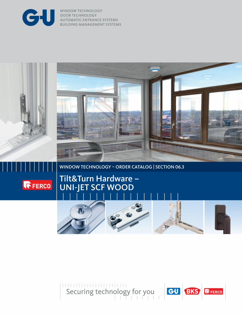
WINDOW TECHNOLOGY – ORDER CATALOG | SECTION 06.3 Tilt&Turn Hardware – UNI-JET SCF WOOD
Transcript of UNI-JET SCF für Kunststoff fenster
GU І WP00376-00-1-2 І 12/2016
UNI-JET SCF für Kunststoff fenster
Produktübersicht
Bezeichnung Falzluft [mm]
Nutlage [mm]
Flügelüberschlagbreite [mm]
Geprüfte Tragfähigkeit der Beschläge [kg]
Max. Flügelfalzbreite [mm]
Max. Flügelfalzhöhe [mm]
UNI-JET SCF 12 9 / 13 max. 22 130 1400 2800
UNI-JET SCF 12 9 / 13 max. 22 160 * 1400 2800
* mit optionaler Lastabtragung 160 kgBei allen Maß- und Gewichtsangaben bitte unsere Anwendungsdiagramme beachten! Weitere Informationen fi nden Sie unter www.g-u.com
Der neue UNI-JET SCF mit neuer, nach innen drehender Kinematik
Scherenarm
Ecklager
Innenansicht
Designvorteile
■ Die neue nach innen drehende Kinematik ermöglicht Designfreiheit
■ Keine sichtbaren Beschlagteile – auch geeignet für den Einsatz in flächenbündigen Fenstern
■ Universal einsetzbar mit dem modularen UNI-JET Zentralverschluss
Leichtes Handling
■ Keine Bohrarbeiten am Fenster
■ Ein-Mann-Montage dank paralleler Einhängung möglich
■ Keine Beschädigung der Beschlagteile beim Einputzen,da im Falzbereich liegend
■ Ein Systemwerkzeug für alle Einstellungen
Einsatzmöglichkeiten
■ Ermöglicht auch dreiflügelige „Schweizer Fenster“
■ Geprüfte Tragfähigkeit der Beschläge bis 130 kg, mit Lastabtragung bis 160 kg
■ Öffnungsweite bis 90°
■ Geprüfte Widerstandsklassen
� UNI-JET SCF Zentralverschluss für Kunststofffenster, Holzfenster und Aluminiumfenster
� UNI-JET SCF Band- und Rahmenbauteile für Kunststofffenster
� UNI-JET SCF Band- und Rahmenbauteile für Holzfenster
Ausgabe 12/2016
FENSTERTECHNIK – BESTELLKATALOG
UNI-JET SCFDie verdecktliegende Bandseite
DAS PRINZIPZENTRALVERSCHLUSS
WINDOW TECHNOLOGY – ORDER CATALOG | SECTION 06.3
Tilt&Turn Hardware –UNI-JET SCF WOOD

Edition 03.2021 06.3.3Information in this document can be modified without notice.
063
Table of Contents
06.3UNI-JET SCF WOODDIRIGENT T&T Handle ................................................................ 06.3.7Tilt&Turn Sash ............................................................................... 06.3.8 Turn-only Sash ............................................................................ 06.3.14 Dummy-mullion Sash with ZH Lever-operated Gear ...........06.3.18Jigs ................................................................................................06.3.21Accessories ................................................................................. 06.3.22
Tilt&Turn Hardware – UNI-JET SCF WOOD

Edition 03.2021 06.3.5Information in this document can be modified without notice.
063
Product Information
Tilt&Turn Hardware – UNI-JET SCF WOOD
UNI-JET Hardware System
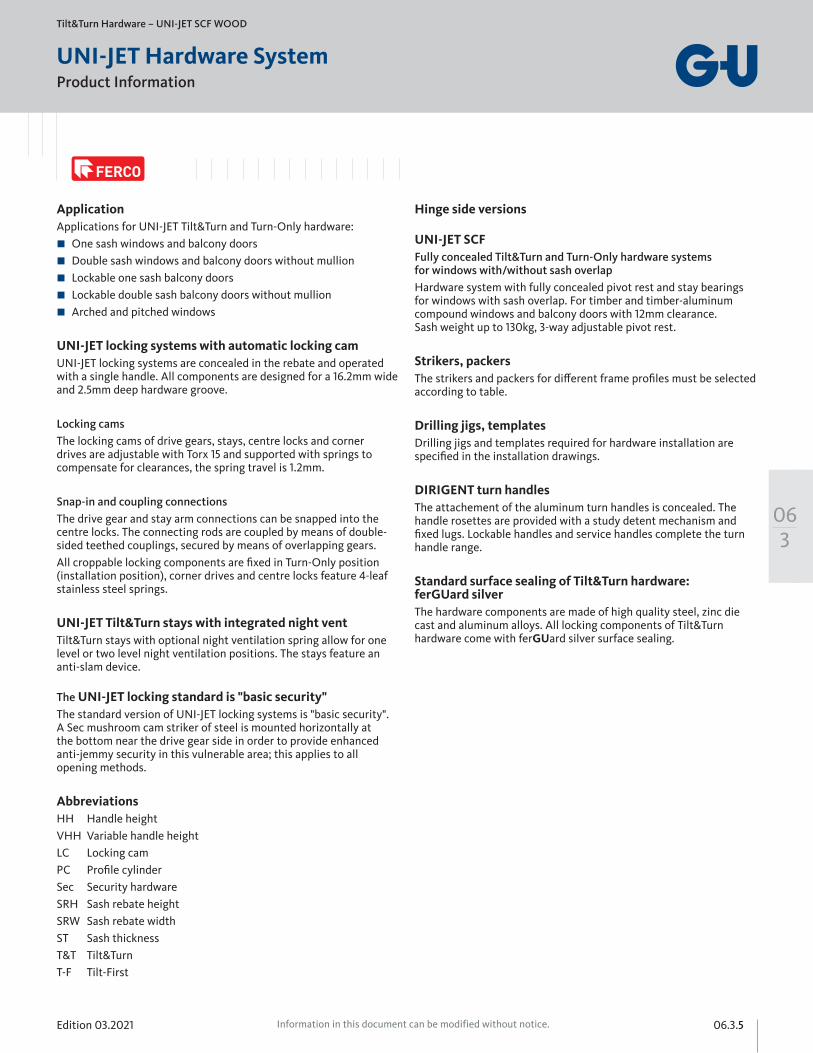
ApplicationApplications for UNI-JET Tilt&Turn and Turn-Only hardware: One sash windows and balcony doors Double sash windows and balcony doors without mullion Lockable one sash balcony doors Lockable double sash balcony doors without mullion Arched and pitched windows
UNI-JET locking systems with automatic locking camUNI-JET locking systems are concealed in the rebate and operated with a single handle. All components are designed for a 16.2mm wide and 2.5mm deep hardware groove.
Locking camsThe locking cams of drive gears, stays, centre locks and corner drives are adjustable with Torx 15 and supported with springs to compensate for clearances, the spring travel is 1.2mm.
Snap-in and coupling connectionsThe drive gear and stay arm connections can be snapped into the centre locks. The connecting rods are coupled by means of double- sided teethed couplings, secured by means of overlapping gears.All croppable locking components are fixed in Turn-Only position (installation position), corner drives and centre locks feature 4-leaf stainless steel springs.
UNI-JET Tilt&Turn stays with integrated night ventTilt&Turn stays with optional night ventilation spring allow for one level or two level night ventilation positions. The stays feature an anti-slam device. The UNI-JET locking standard is "basic security"The standard version of UNI-JET locking systems is "basic security". A Sec mushroom cam striker of steel is mounted horizontally at the bottom near the drive gear side in order to provide enhanced anti-jemmy security in this vulnerable area; this applies to all opening methods.
AbbreviationsHH Handle heightVHH Variable handle heightLC Locking camPC Profile cylinderSec Security hardwareSRH Sash rebate heightSRW Sash rebate widthST Sash thicknessT&T Tilt&TurnT-F Tilt-First
Hinge side versions UNI-JET SCF Fully concealed Tilt&Turn and Turn-Only hardware systems for windows with/without sash overlapHardware system with fully concealed pivot rest and stay bearings for windows with sash overlap. For timber and timber-aluminum compound windows and balcony doors with 12mm clearance. Sash weight up to 130kg, 3-way adjustable pivot rest.
Strikers, packersThe strikers and packers for different frame profiles must be selected according to table.
Drilling jigs, templatesDrilling jigs and templates required for hardware installation are specified in the installation drawings.
DIRIGENT turn handlesThe attachement of the aluminum turn handles is concealed. The handle rosettes are provided with a study detent mechanism and fixed lugs. Lockable handles and service handles complete the turn handle range.
Standard surface sealing of Tilt&Turn hardware: ferGUard silverThe hardware components are made of high quality steel, zinc die cast and aluminum alloys. All locking components of Tilt&Turn hardware come with ferGUard silver surface sealing.
Edition 03.202106.3.6 Information in this document can be modified without notice.
SRH
[mm
]
SRW [mm]
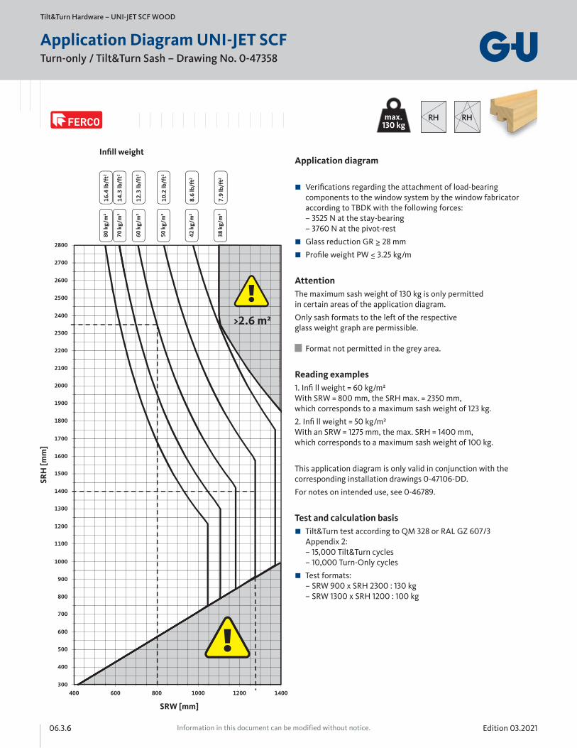
Turn-only / Tilt&Turn Sash – Drawing No. 0-47358
Tilt&Turn Hardware – UNI-JET SCF WOOD
Application Diagram UNI-JET SCF
Application diagram
Verifications regarding the attachment of load-bearing components to the window system by the window fabricator according to TBDK with the following forces: – 3525 N at the stay-bearing – 3760 N at the pivot-rest
Glass reduction GR ≥ 28 mm
Profile weight PW ≤ 3.25 kg/m
AttentionThe maximum sash weight of 130 kg is only permitted in certain areas of the application diagram.
Only sash formats to the left of the respective glass weight graph are permissible. Format not permitted in the grey area.
Reading examples1. Infi ll weight = 60 kg/m² With SRW = 800 mm, the SRH max. = 2350 mm, which corresponds to a maximum sash weight of 123 kg.
2. Infi ll weight = 50 kg/m² With an SRW = 1275 mm, the max. SRH = 1400 mm, which corresponds to a maximum sash weight of 100 kg.
This application diagram is only valid in conjunction with the corresponding installation drawings 0-47106-DD.
For notes on intended use, see 0-46789.
Test and calculation basis Tilt&Turn test according to QM 328 or RAL GZ 607/3 Appendix 2: – 15,000 Tilt&Turn cycles – 10,000 Turn-Only cycles
Test formats: – SRW 900 x SRH 2300 : 130 kg – SRW 1300 x SRH 1200 : 100 kg
SRH
[mm
]
SRW [mm]
16.4
lb/f
t2
14.3
lb/f
t2
12.3
lb/f
t2
10.2
lb/f
t2
8.6
lb/f
t2
7.9
lb/f
t2
RHRHmax.130 kg
Edition 03.2021 06.3.7Information in this document can be modified without notice.
063
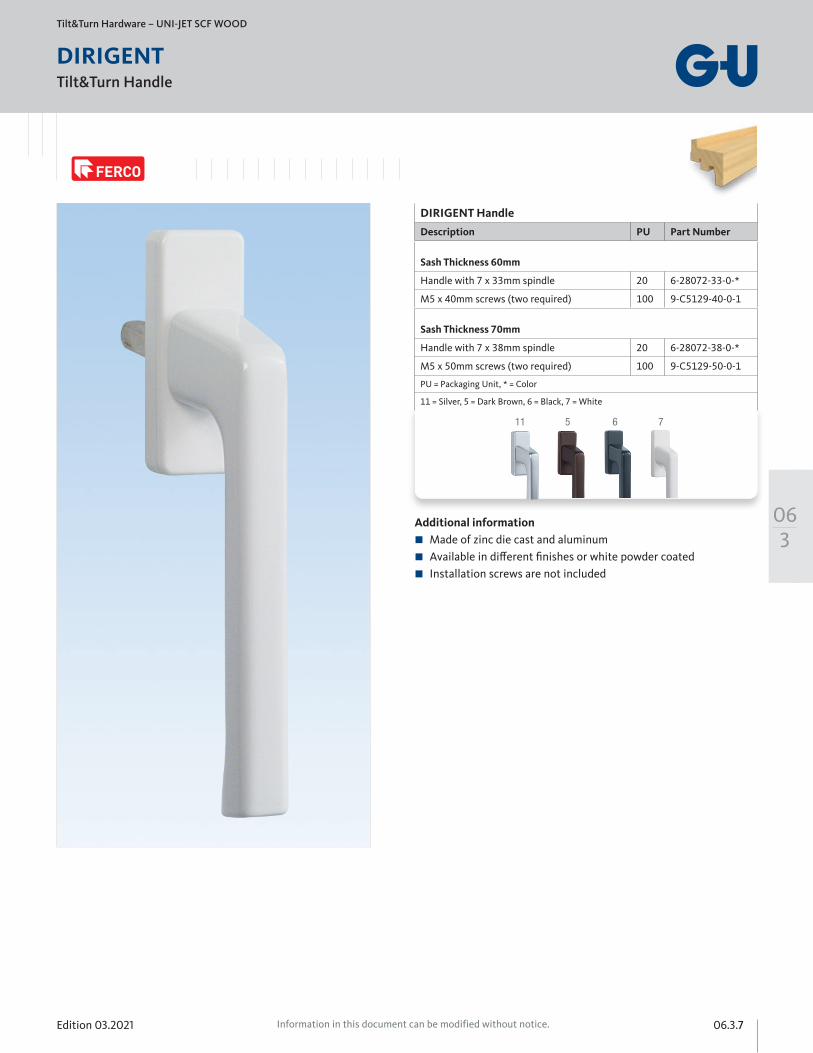
Tilt&Turn Handle
Tilt&Turn Hardware – UNI-JET SCF WOOD
DIRIGENT
711 5 6
Additional information Made of zinc die cast and aluminum Available in different finishes or white powder coated Installation screws are not included
DIRIGENT Handle
Description PU Part Number
Sash Thickness 60mm
Handle with 7 x 33mm spindle 20 6-28072-33-0-*
M5 x 40mm screws (two required) 100 9-C5129-40-0-1
Sash Thickness 70mm
Handle with 7 x 38mm spindle 20 6-28072-38-0-*
M5 x 50mm screws (two required) 100 9-C5129-50-0-1
PU = Packaging Unit, * = Color
11 = Silver, 5 = Dark Brown, 6 = Black, 7 = White

Edition 03.202106.3.8 Information in this document can be modified without notice.
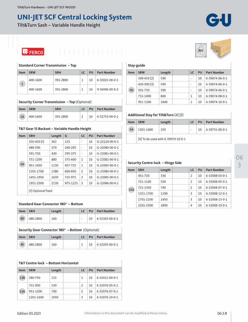
Tilt&Turn Sash – Variable Handle Height
Tilt&Turn Hardware – UNI-JET SCF WOOD
UNI-JET SCF Central Locking System
RH
1A
3G
13G
4E
11
11
22or
23
Edition 03.2021 06.3.9Information in this document can be modified without notice.
063
RH
Tilt&Turn Sash – Variable Handle Height
Tilt&Turn Hardware – UNI-JET SCF WOOD
UNI-JET SCF Central Locking System
Stay-guide
Item SRW Length LC PU Part Number
390-419 [2] 590 - 10 6-39074-06-0-1
420-500 [3] 590 - 10 6-39074-06-0-1
501-750 590 - 10 6-39074-06-0-1
751-1000 840 1 10 6-39074-08-0-1
951-1200 1040 1 10 6-39074-10-0-1
3G
Standard Corner Transmission – Top
Item SRW SRH LC PU Part Number
400-1600 391-2800 1 10 6-32021-00-0-1
400-1600 391-2800 1 10 9-36996-00-0-2
Security Corner Transmission – Top (Optional)
Item SRW SRH LC PU Part Number
400-1600 391-2800 2 10 6-31753-00-0-11A
T&T Gear 15 Backset – Variable Handle Height
Item SRH Length G LC PU Part Number
350-450 [1] 363 155 - 10 G-22120-00-0-1
480-590 270 240-295 - 10 G-22080-00-0-1
591-750 430 295-375 - 10 G-22081-00-0-1
751-1200 880 375-600 1 10 G-22082-00-0-1
951-1450 1130 457-725 1 10 G-22083-00-0-1
1201-1700 1380 600-850 2 10 G-22084-00-0-1
1451-1950 1630 725-975 2 10 G-22085-00-0-1
1951-2500 2130 975-1225 3 10 G-22086-00-0-1
[1] Optional fixed
2A
Standard Gear Connector 180⁰ – Bottom
Item SRH Length LC PU Part Number
480-2800 160 - 10 6-32303-00-0-14D
Security Gear Connector 180⁰ – Bottom (Optional)
Item SRH Length LC PU Part Number
480-2800 160 1 10 6-33205-00-0-14E
T&T Centre-lock – Bottom Horizontal
Item SRW Length LC PU Part Number
280-750 215 1 10 6-32012-00-0-1
751-950 530 2 10 6-32076-05-0-1
951-1200 740 2 10 6-32076-07-0-1
1201-1600 1050 3 10 6-32076-10-0-1
13B
13A
Security Centre-lock – Hinge Side
Item SRH Length LC PU Part Number
451-720 330 2 10 6-32008-03-0-1
721-1100 530 2 10 6-32008-05-0-1
721-1350 740 2 10 6-32008-07-0-1
1351-1700 1190 3 10 6-32008-12-0-1
1701-2100 1450 3 10 6-32008-15-0-1
2101-2500 1890 4 10 6-32008-19-0-1
13G
Additional Stay for Tilt&Turn [4] [5]
Item SRW Length LC PU Part Number
1201-1400 250 - 10 6-39731-00-0-1
[4] To be used with 6-39074-10-0-1
3A
1
Edition 03.202106.3.10 Information in this document can be modified without notice.
Tilt&Turn Sash – Variable Handle Height
Tilt&Turn Hardware – UNI-JET SCF WOOD
UNI-JET SFC Central Locking System
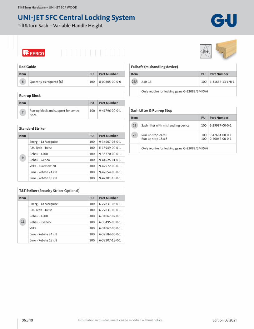
Rod Guide
Item PU Part Number
Quantity as required [6] 100 8-00805-00-0-06
Standard Striker
Item PU Part Number
Energi - La Marquise 100 9-34907-03-0-1
P.H. Tech - Twist 100 E-18949-00-0-1
Rehau - 4500 100 9-35770-00-0-1
Rehau - Geneo 100 9-44525-01-0-1
Veka - Euroview 70 100 9-42972-00-0-1
Euro - Rebate 24 x 8 100 9-42654-00-0-1
Euro - Rebate 18 x 8 100 9-42301-18-0-1
9
T&T Striker (Security Striker Optional)
Item PU Part Number
Energi - La Marquise 100 6-27831-05-0-1
P.H. Tech - Twist 100 6-27831-06-0-1
Rehau - 4500 100 6-31067-07-0-1
Rehau - Geneo 100 6-30495-05-0-1
Veka 100 6-31067-05-0-1
Euro - Rebate 24 x 8 100 6-32584-00-0-1
Euro - Rebate 18 x 8 100 6-32207-18-0-1
11
Run-up Block
Item PU Part Number
Run-up block and support for centre locks
100 9-41796-00-0-17
RH
Failsafe (mishandling device)
Item PU Part Number
Axis 13 100 6-31657-13-L/R-1
Only require for locking gears G-22082/3/4/5/6
22A
Sash Lifter & Run-up Stop
Item PU Part Number
Sash lifter with mishandling device 100 6-29987-00-0-1
Run-up stop 24 x 8 Run-up stop 18 x 8
100 100
9-42684-00-0-1 9-40067-00-0-1
Only require for locking gears G-22082/3/4/5/6
22
23

Edition 03.2021 06.3.11Information in this document can be modified without notice.
063
Tilt&Turn Sash – Variable Handle Height
Tilt&Turn Hardware – UNI-JET SCF WOOD
UNI-JET SFC Central Locking System
[1] SRH 280–390 only possible in conjunction with corner-drive S 6-32238 or corner-drive SLK 6-32224 and anti-slam device 9-38688-33. Installation according to drawing 0-45986.
[2] If the centre fixing (at the connecting rod) is detached and removed from the connecting rod prior to assembly of the stay-guide (in conjunction with corner-drive S 6-32238 or corner-drive SLK 6-32224), the SRW can be reduced to 390–419.
[3] SRW 420–500 only possible in conjunction with corner-drive S 6-32238 or corner-drive SLK 6-32224. Installation according to drawing 0-45986.
[4] Use additional stay with SRW 1201–1400. Installation according to drawing 0-46684.
[5] With PVC windows it is necessary to use 2 profile-specific packers for each additional stay.
[6] When cropping the faceplate by less than 150 mm or when the notches are still visible after cropping, rod guide 8-00805 should be positioned at least 65 mm from the faceplate end.
[7] With SRH > 2350 or > 2450, extension 500, respectively 250 must be used.
VHH gear SRH 2451–2700: use extension 250 uncropped and crop the drive-gear at the top (0 up to 250 mm) according to SRH.
SRH 2701–2800: use extension 500 cropped to dim. 350 and crop the drivegear at the top (0 up to 100 mm) according to SRH.
RH
Edition 03.202106.3.12 Information in this document can be modified without notice.
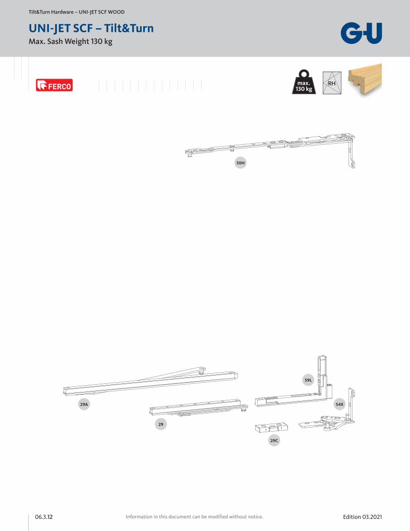
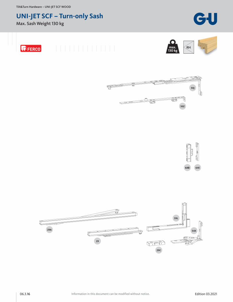
Max. Sash Weight 130 kg
Tilt&Turn Hardware – UNI-JET SCF WOOD
UNI-JET SCF – Tilt&Turn
max.130 kg
RH
Edition 03.2021 06.3.13Information in this document can be modified without notice.
063
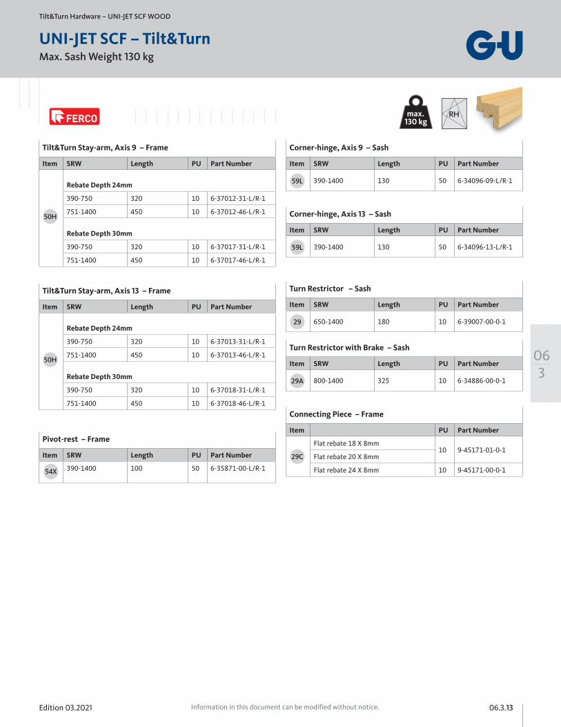
Max. Sash Weight 130 kg
Tilt&Turn Hardware – UNI-JET SCF WOOD
UNI-JET SCF – Tilt&Turn
Tilt&Turn Stay-arm, Axis 9 – Frame
Item SRW Length PU Part Number
Rebate Depth 24mm
390-750 320 10 6-37012-31-L/R-1
751-1400 450 10 6-37012-46-L/R-1
Rebate Depth 30mm
390-750 320 10 6-37017-31-L/R-1
751-1400 450 10 6-37017-46-L/R-1
Tilt&Turn Stay-arm, Axis 13 – Frame
Item SRW Length PU Part Number
Rebate Depth 24mm
390-750 320 10 6-37013-31-L/R-1
751-1400 450 10 6-37013-46-L/R-1
Rebate Depth 30mm
390-750 320 10 6-37018-31-L/R-1
751-1400 450 10 6-37018-46-L/R-1
Corner-hinge, Axis 9 – Sash
Item SRW Length PU Part Number
390-1400 130 50 6-34096-09-L/R-1
50H
50H
Pivot-rest – Frame
Item SRW Length PU Part Number
390-1400 100 50 6-35871-00-L/R-154X
59L
Corner-hinge, Axis 13 – Sash
Item SRW Length PU Part Number
390-1400 130 50 6-34096-13-L/R-159L
Turn Restrictor – Sash
Item SRW Length PU Part Number
650-1400 180 10 6-39007-00-0-1
Turn Restrictor with Brake – Sash
Item SRW Length PU Part Number
800-1400 325 10 6-34886-00-0-1
29
29A
Connecting Piece – Frame
Item PU Part Number
Flat rebate 18 X 8mm10 9-45171-01-0-1
Flat rebate 20 X 8mm
Flat rebate 24 X 8mm 10 9-45171-00-0-1
29C
max.130 kg
RH
Edition 03.202106.3.14 Information in this document can be modified without notice.
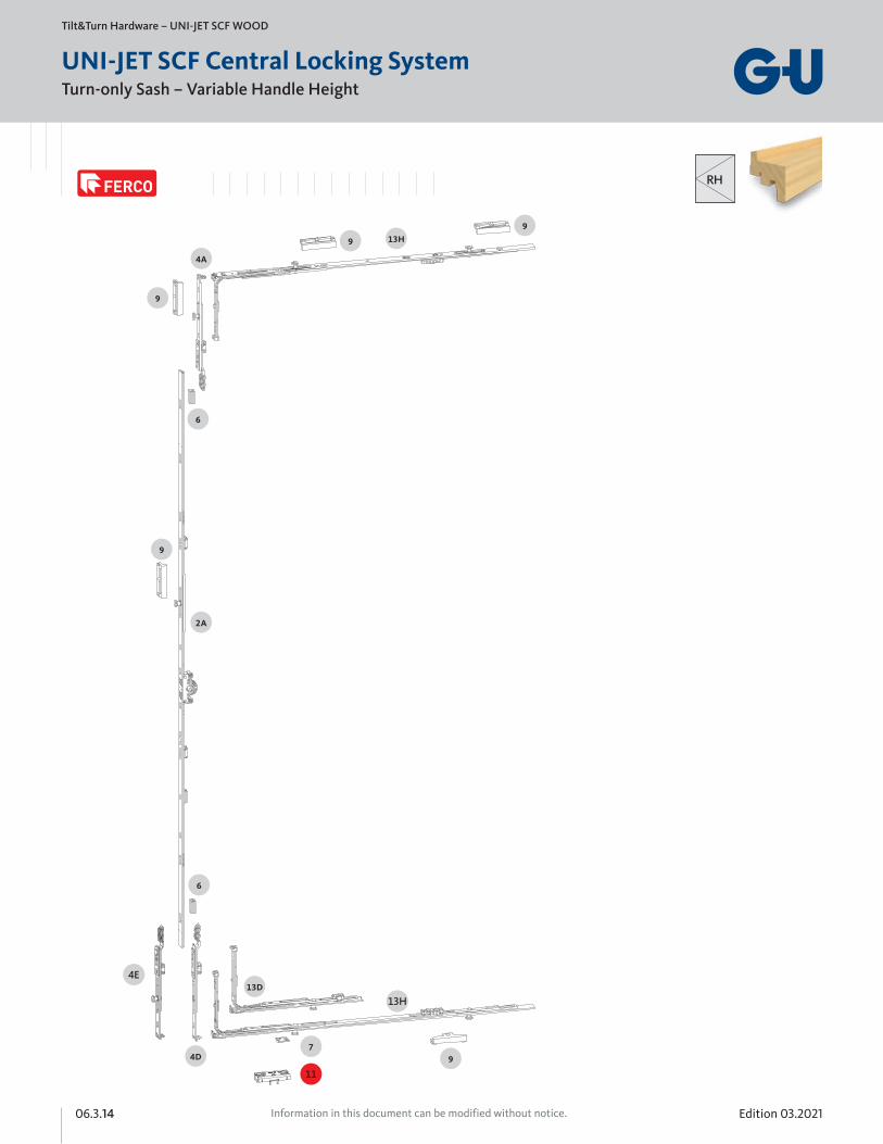
Turn-only Sash – Variable Handle Height
Tilt&Turn Hardware – UNI-JET SCF WOOD
UNI-JET SCF Central Locking System
4E
13H
11
RH
Edition 03.2021 06.3.15Information in this document can be modified without notice.
063
Turn-only Sash – Variable Handle Height
Tilt&Turn Hardware – UNI-JET SCF WOOD
UNI-JET SCF Central Locking System
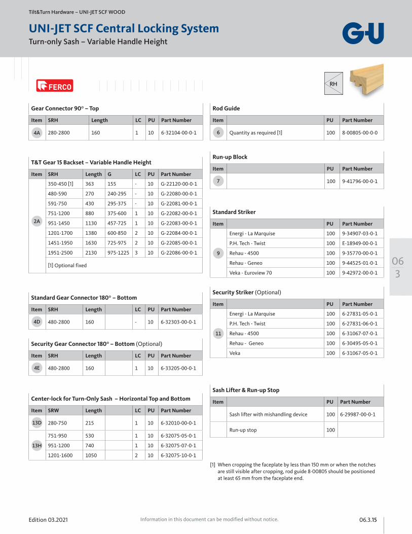
Gear Connector 90⁰ – Top
Item SRH Length LC PU Part Number
280-2800 160 1 10 6-32104-00-0-1
Standard Gear Connector 180⁰ – Bottom
Item SRH Length LC PU Part Number
480-2800 160 - 10 6-32303-00-0-14D
Security Gear Connector 180⁰ – Bottom (Optional)
Item SRH Length LC PU Part Number
480-2800 160 1 10 6-33205-00-0-14E
4A
Center-lock for Turn-Only Sash – Horizontal Top and Bottom
Item SRW Length LC PU Part Number
280-750 215 1 10 6-32010-00-0-1
751-950 530 1 10 6-32075-05-0-1
951-1200 740 1 10 6-32075-07-0-1
1201-1600 1050 2 10 6-32075-10-0-1
13D
13H
Rod Guide
Item PU Part Number
Quantity as required [1] 100 8-00805-00-0-06
Run-up Block
Item PU Part Number
100 9-41796-00-0-17
[1] When cropping the faceplate by less than 150 mm or when the notches are still visible after cropping, rod guide 8-00805 should be positioned at least 65 mm from the faceplate end.
T&T Gear 15 Backset – Variable Handle Height
Item SRH Length G LC PU Part Number
350-450 [1] 363 155 - 10 G-22120-00-0-1
480-590 270 240-295 - 10 G-22080-00-0-1
591-750 430 295-375 - 10 G-22081-00-0-1
751-1200 880 375-600 1 10 G-22082-00-0-1
951-1450 1130 457-725 1 10 G-22083-00-0-1
1201-1700 1380 600-850 2 10 G-22084-00-0-1
1451-1950 1630 725-975 2 10 G-22085-00-0-1
1951-2500 2130 975-1225 3 10 G-22086-00-0-1
[1] Optional fixed
2A
Standard Striker
Item PU Part Number
Energi - La Marquise 100 9-34907-03-0-1
P.H. Tech - Twist 100 E-18949-00-0-1
Rehau - 4500 100 9-35770-00-0-1
Rehau - Geneo 100 9-44525-01-0-1
Veka - Euroview 70 100 9-42972-00-0-1
9
Sash Lifter & Run-up Stop
Item PU Part Number
Sash lifter with mishandling device 100 6-29987-00-0-1
Run-up stop 100
Security Striker (Optional)
Item PU Part Number
Energi - La Marquise 100 6-27831-05-0-1
P.H. Tech - Twist 100 6-27831-06-0-1
Rehau - 4500 100 6-31067-07-0-1
Rehau - Geneo 100 6-30495-05-0-1
Veka 100 6-31067-05-0-1
11
RH
Edition 03.202106.3.16 Information in this document can be modified without notice.
Max. Sash Weight 130 kg
Tilt&Turn Hardware – UNI-JET SCF WOOD
UNI-JET SCF – Turn-only Sash
64B
max.130 kg
RH
Edition 03.2021 06.3.17Information in this document can be modified without notice.
063
Max. Sash Weight 130 kg
Tilt&Turn Hardware – UNI-JET SCF WOOD
UNI-JET SCF – Turn-only Sash
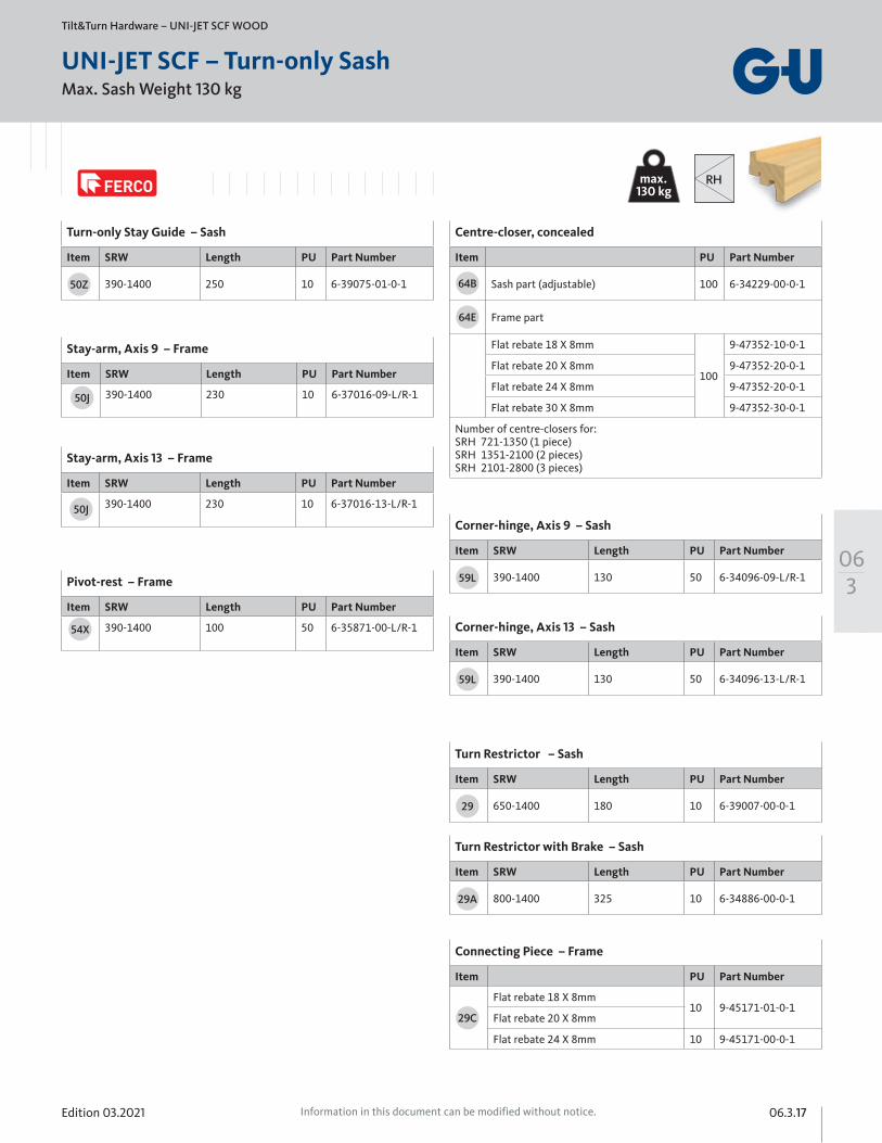
Turn-only Stay Guide – Sash
Item SRW Length PU Part Number
390-1400 250 10 6-39075-01-0-150Z
Centre-closer, concealed
Item PU Part Number
Sash part (adjustable) 100 6-34229-00-0-1
Frame part
Flat rebate 18 X 8mm
100
9-47352-10-0-1
Flat rebate 20 X 8mm 9-47352-20-0-1
Flat rebate 24 X 8mm 9-47352-20-0-1
Flat rebate 30 X 8mm 9-47352-30-0-1
Number of centre-closers for: SRH 721-1350 (1 piece) SRH 1351-2100 (2 pieces) SRH 2101-2800 (3 pieces)
64B
64E
Stay-arm, Axis 9 – Frame
Item SRW Length PU Part Number
390-1400 230 10 6-37016-09-L/R-1
Stay-arm, Axis 13 – Frame
Item SRW Length PU Part Number
390-1400 230 10 6-37016-13-L/R-1
Corner-hinge, Axis 9 – Sash
Item SRW Length PU Part Number
390-1400 130 50 6-34096-09-L/R-1
Corner-hinge, Axis 13 – Sash
Item SRW Length PU Part Number
390-1400 130 50 6-34096-13-L/R-1
50J
50J
Pivot-rest – Frame
Item SRW Length PU Part Number
390-1400 100 50 6-35871-00-L/R-154X
59L
59L
Turn Restrictor – Sash
Item SRW Length PU Part Number
650-1400 180 10 6-39007-00-0-1
Turn Restrictor with Brake – Sash
Item SRW Length PU Part Number
800-1400 325 10 6-34886-00-0-1
29
29A
Connecting Piece – Frame
Item PU Part Number
Flat rebate 18 X 8mm10 9-45171-01-0-1
Flat rebate 20 X 8mm
Flat rebate 24 X 8mm 10 9-45171-00-0-1
29C
max.130 kg
RH
Edition 03.202106.3.18 Information in this document can be modified without notice.
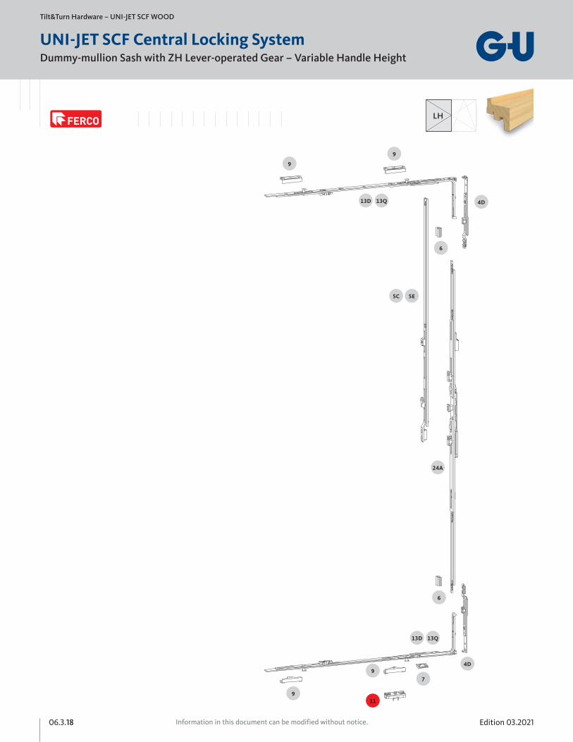
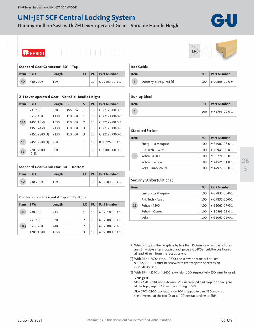
Dummy-mullion Sash with ZH Lever-operated Gear – Variable Handle Height
Tilt&Turn Hardware – UNI-JET SCF WOOD
UNI-JET SCF Central Locking System
LH
Edition 03.2021 06.3.19Information in this document can be modified without notice.
063
Dummy-mullion Sash with ZH Lever-operated Gear – Variable Handle Height
Tilt&Turn Hardware – UNI-JET SCF WOOD
UNI-JET SCF Central Locking System
LH
ZH Lever-operated Gear – Variable Handle Height
Item SRH Length G S PU Part Number
781-950 630 356-536 1 10 G-22170-00-0-1
951-1450 1130 310-560 1 10 G-22171-00-0-1
1451-1950 1630 310-560 2 10 G-22172-00-0-1
1951-2450 2130 310-560 3 10 G-22173-00-0-1
2451-2800 [3] 2130 310-560 3 10 G-22173-00-0-1
2451-2700 [3] 250 - - 10 8-00625-00-0-1
2701-2800 [2] [3]
500 - 10 G-21040-00-0-1
24A
5C
5E
Standard Gear Connector 180⁰ – Bottom
Item SRH Length LC PU Part Number
780-2800 160 - 10 6-32303-00-0-14D
Standard Gear Connector 180⁰ – Top
Item SRH Length LC PU Part Number
480-2800 160 - 10 6-32303-00-0-14D
Center-lock – Horizontal Top and Bottom
Item SRW Length LC PU Part Number
280-750 215 1 10 6-32010-00-0-1
751-950 530 2 10 6-32008-05-0-1
951-1200 740 2 10 6-32008-07-0-1
1201-1600 1050 3 10 6-32008-10-0-1
13D
13Q
[1] When cropping the faceplate by less than 150 mm or when the notches are still visible after cropping, rod guide 8-00805 should be positioned at least 65 mm from the faceplate end.
[2] With SRH > 2600, resp. > 2700, the screw-on standard striker 9-30256-00-0-1 must be screwed to the faceplate of extension G-21040-00-0-1.
[3] With SRH > 2350 or > 2450, extension 500, respectively 250 must be used.
VHH gear SRH 2450–2700: use extension 250 uncropped and crop the drive-gear at the top (0 up to 250 mm) according to SRH.
SRH 2701–2800: use extension 500 cropped to dim. 350 and crop the drivegear at the top (0 up to 100 mm) according to SRH.
Rod Guide
Item PU Part Number
Quantity as required [1] 100 8-00805-00-0-06
Run-up Block
Item PU Part Number
100 9-41796-00-0-17
Standard Striker
Item PU Part Number
Energi - La Marquise 100 9-34907-03-0-1
P.H. Tech - Twist 100 E-18949-00-0-1
Rehau - 4500 100 9-35770-00-0-1
Rehau - Geneo 100 9-44525-01-0-1
Veka - Euroview 70 100 9-42972-00-0-1
9
Security Striker (Optional)
Item PU Part Number
Energi - La Marquise 100 6-27831-05-0-1
P.H. Tech - Twist 100 6-27831-06-0-1
Rehau - 4500 100 6-31067-07-0-1
Rehau - Geneo 100 6-30495-05-0-1
Veka 100 6-31067-05-0-1
11
Edition 03.202106.3.20 Information in this document can be modified without notice.
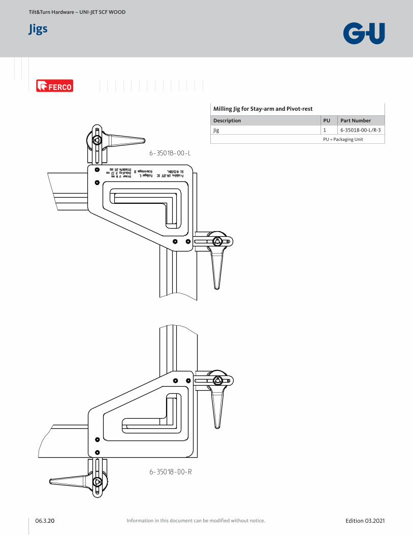
Tilt&Turn Hardware – UNI-JET SCF WOOD
Jigs
Milling Jig for Stay-arm and Pivot-rest
Description PU Part Number
Jig 1 6-35018-00-L/R-3
PU = Packaging Unit
Edition 03.2021 06.3.21Information in this document can be modified without notice.
063
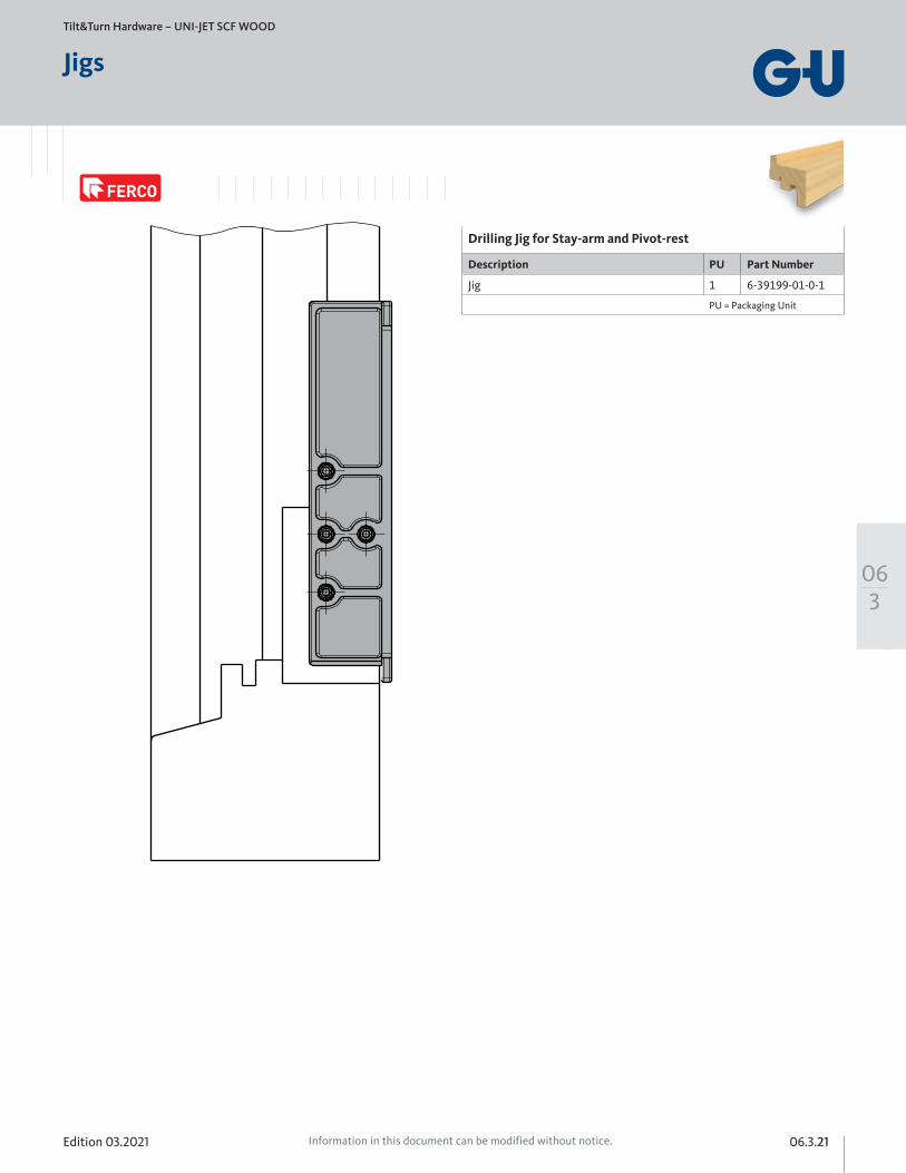
Tilt&Turn Hardware – UNI-JET SCF WOOD
Jigs
Drilling Jig for Stay-arm and Pivot-rest
Description PU Part Number
Jig 1 6-39199-01-0-1
PU = Packaging Unit
Ø3
18
Edition 03.202106.3.22 Information in this document can be modified without notice.
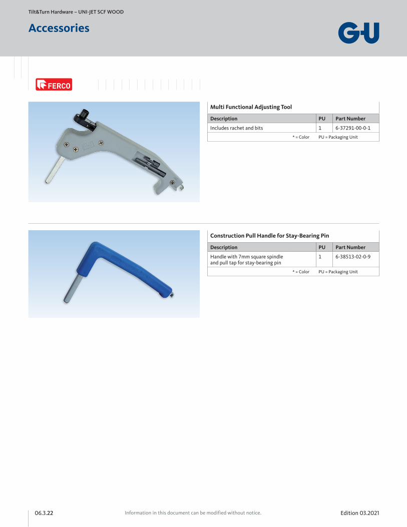
Multi Functional Adjusting Tool
Description PU Part Number
Includes rachet and bits 1 6-37291-00-0-1
* = Color PU = Packaging Unit
Tilt&Turn Hardware – UNI-JET SCF WOOD
Accessories
Construction Pull Handle for Stay-Bearing Pin
Description PU Part Number
Handle with 7mm square spindle and pull tap for stay-bearing pin
1 6-38513-02-0-9
* = Color PU = Packaging Unit
Edition 03.2021 06.3.23Information in this document can be modified without notice.
063
Tilt&Turn Hardware – UNI-JET SCF WOOD
Accessories
Torx 15 Adjusting Key
Description PU Part Number
U-shaped 110 x 100 x 25mm 1 9-43631-00-0-6
* = Color PU = Packaging Unit
Torx Allen Key for Unijet Cam Adjustment
Description PU Part Number
L-shaped 100 x 24mm 1 H-00809-15-0-0
* = Color PU = Packaging Unit
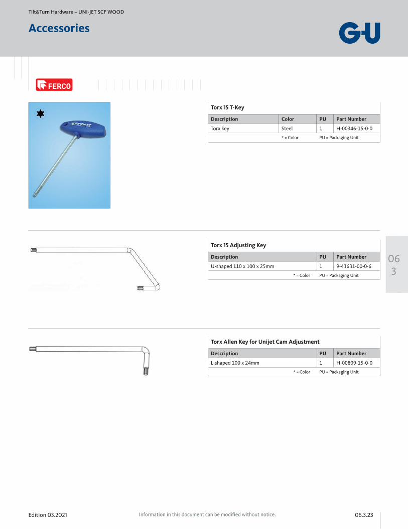
Torx 15 T-Key
Description Color PU Part Number
Torx key Steel 1 H-00346-15-0-0
* = Color PU = Packaging Unit
Edition 03.202106.3.24 Information in this document can be modified without notice.
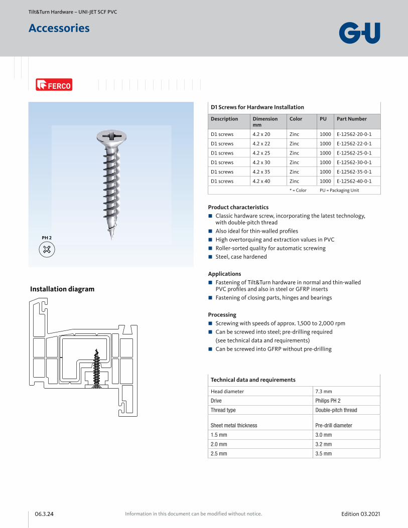
Technical data and requirements
Head diameter 7.3 mm
Drive Philips PH 2
Thread type Double-pitch thread
Sheet metal thickness
Pre-drill diameter
1.5 mm 3.0 mm
2.0 mm 3.2 mm
2.5 mm 3.5 mm
D1 Screws for Hardware Installation
Description Dimensionmm
Color PU Part Number
D1 screws 4.2 x 20 Zinc 1000 E-12562-20-0-1
D1 screws 4.2 x 22 Zinc 1000 E-12562-22-0-1
D1 screws 4.2 x 25 Zinc 1000 E-12562-25-0-1
D1 screws 4.2 x 30 Zinc 1000 E-12562-30-0-1
D1 screws 4.2 x 35 Zinc 1000 E-12562-35-0-1
D1 screws 4.2 x 40 Zinc 1000 E-12562-40-0-1
* = Color PU = Packaging Unit
Product characteristics Classic hardware screw, incorporating the latest technology, with double-pitch thread Also ideal for thin-walled profiles High overtorquing and extraction values in PVC Roller-sorted quality for automatic screwing Steel, case hardened
Applications Fastening of Tilt&Turn hardware in normal and thin-walled PVC profiles and also in steel or GFRP inserts Fastening of closing parts, hinges and bearings
Processing Screwing with speeds of approx. 1,500 to 2,000 rpm Can be screwed into steel; pre-drilling required (see technical data and requirements) Can be screwed into GFRP without pre-drilling
Tilt&Turn Hardware – UNI-JET SCF PVC
Accessories
Installation diagram
Edition 03.2021 06.3.25Information in this document can be modified without notice.
063
Tilt&Turn Hardware – UNI-JET SCF WOOD
Notes
Edition 03.202106.3.26 Information in this document can be modified without notice.
HEAD OFFICEFerco Architectural Hardware Inc.2000, Berlier St.Laval, QC H7L 4S4Tel.: 450 973-1437 1 800 355-8810Fax: 450 [email protected]
www.ferco.ca
ONTARIO / WESTERN PROVINCESTel.: 905 282-9588 1 800 668-5310Fax: 905 282-9915
UNITED STATESTel.: 1 800 927-1097Fax: 1 888 454-0161
Edit
ion
03.
2021
| Pr
inte
d in
Can
ada