Anwendungen der Simulation im Bereich additive Fertigung
32
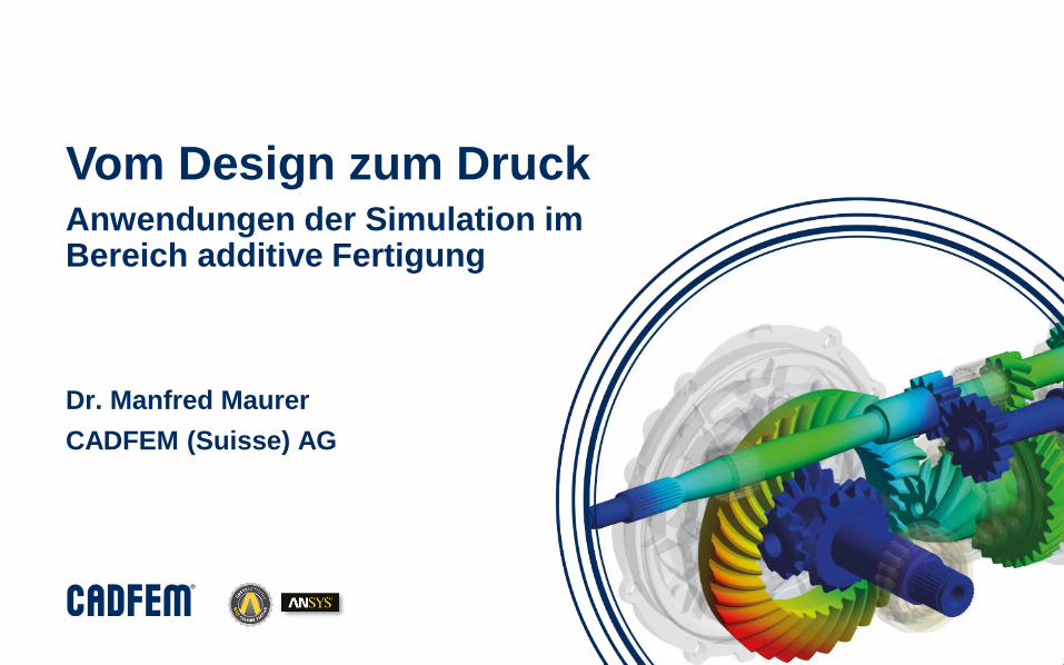
© CADFEM (Suisse) AG, 2019 Vom Design zum Druck Anwendungen der Simulation im Bereich additive Fertigung Dr. Manfred Maurer CADFEM (Suisse) AG
Transcript of Anwendungen der Simulation im Bereich additive Fertigung
© CADFEM (Suisse) AG, 2019
Vom Design zum DruckAnwendungen der Simulation im Bereich additive Fertigung
Dr. Manfred Maurer
CADFEM (Suisse) AG
© CADFEM (Suisse) AG, 2019
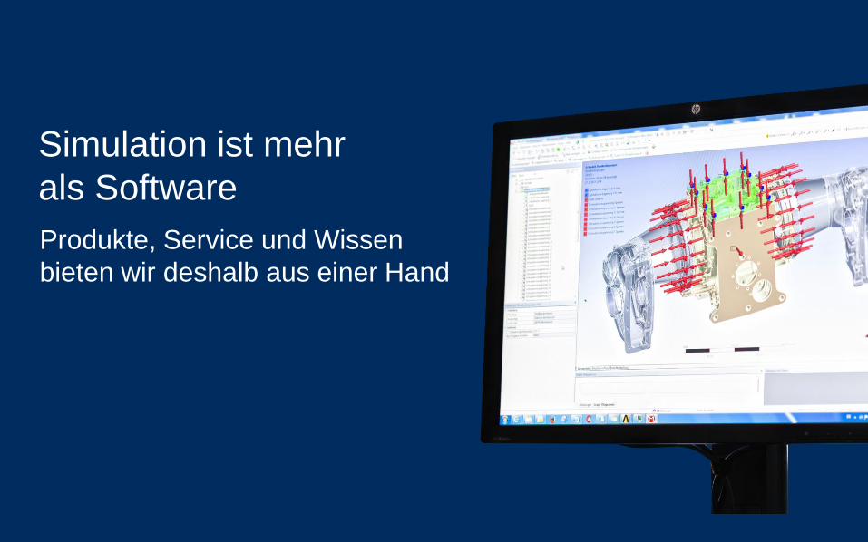
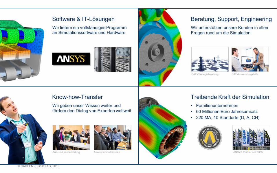
Simulation ist mehr
als Software
Produkte, Service und Wissen
bieten wir deshalb aus einer Hand
© CADFEM (Suisse) AG, 2019

© CADFEM (Suisse) AG, 2019
Additive Manufacturing
4

© CADFEM (Suisse) AG, 2019
Metal AM – Powder Bed Fusion
ScannerLaser
Powder delivery piston
Fabrication powder bed
Fabrication piston
PowderDeliverysystem
Object beingfabricated
Roller
5
© CADFEM (Suisse) AG, 2019
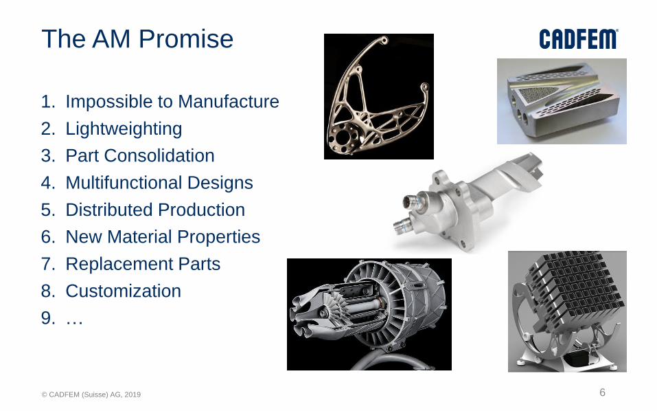
The AM Promise
1. Impossible to Manufacture
2. Lightweighting
3. Part Consolidation
4. Multifunctional Designs
5. Distributed Production
6. New Material Properties
7. Replacement Parts
8. Customization
9. …
6

© CADFEM (Suisse) AG, 2019
Current AM Workflow
DesignBuild job
preparationPrint Measure
Expensive iterations due to failed prints
Recoatercollision
Supports detach Deformation of partCracks in part
7
A.D. Rollet et al.
Porosity in part

© CADFEM (Suisse) AG, 2019 8
© CADFEM (Suisse) AG, 2019
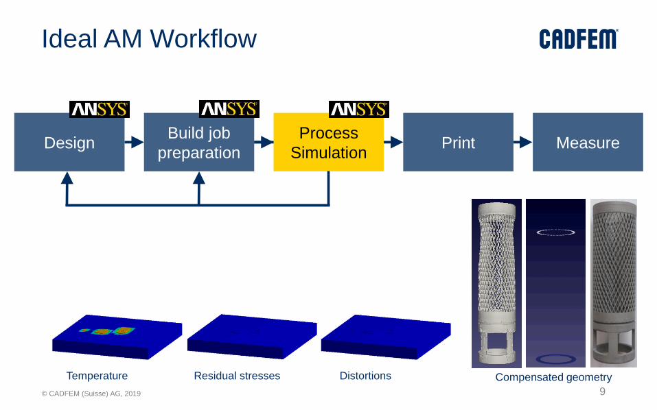
Ideal AM Workflow
DesignBuild job
preparationPrint Measure
Process
Simulation
Compensated geometryTemperature DistortionsResidual stresses
9
© CADFEM (Suisse) AG, 2019
Design for AM
10
© CADFEM (Suisse) AG, 2019
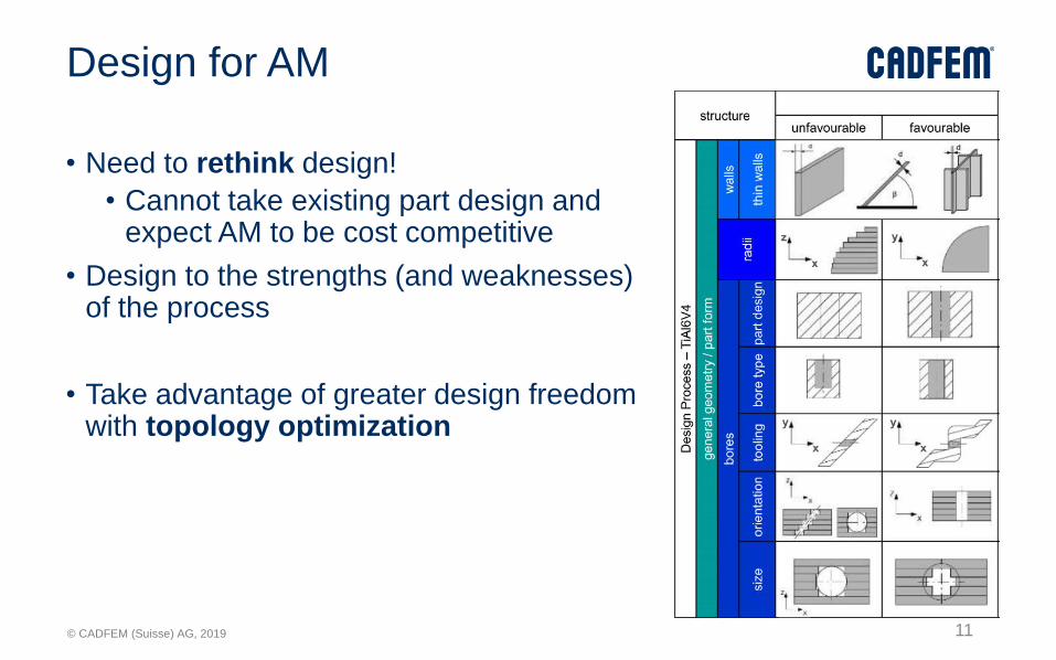
Design for AM
• Need to rethink design!
• Cannot take existing part design and expect AM to be cost competitive
• Design to the strengths (and weaknesses) of the process
• Take advantage of greater design freedom with topology optimization
11

© CADFEM (Suisse) AG, 2019
Application Example: Vacuum Gripper
12
© CADFEM (Suisse) AG, 2019
Process Simulation
13

© CADFEM (Suisse) AG, 2019
Additive Print
• For the machine operators/manufacturing engineers – no simulation experience necessary
• Quick print evaluation
• Distortion and stresses
• Optimize orientation and support structures
• Compensate for distortion
• Detect blade crash
14
© CADFEM (Suisse) AG, 2019
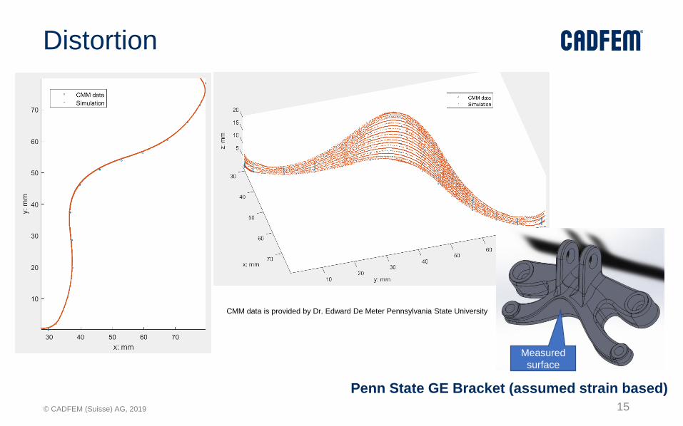
Distortion
Measured
surface
CMM data is provided by Dr. Edward De Meter Pennsylvania State University
Penn State GE Bracket (assumed strain based)
15

© CADFEM (Suisse) AG, 2019
Example – Heat Exchanger
Distortion often happens at the top of aligned holes
• Can simulation predict this phenomenon?
• What level of simulation is needed?
Thin walled complex parts can be simulated
16
© CADFEM (Suisse) AG, 2019
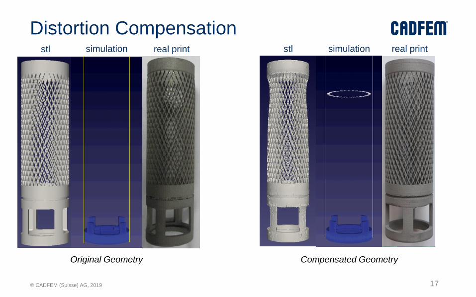
Distortion Compensation
Compensated GeometryOriginal Geometry
17
stl stlsimulation simulationreal print real print

© CADFEM (Suisse) AG, 2019
Example – Conformal Cooling
• Conformal cooling allows for optimizing cooling and flow rates by allowing for channels not manufacturable via conventional methods
• However, it is usually important that there are no support structures inside the cooling channels
• Powder removal from small channels can also be an issue
• Run without supports direct to build plate
18
© CADFEM (Suisse) AG, 2019
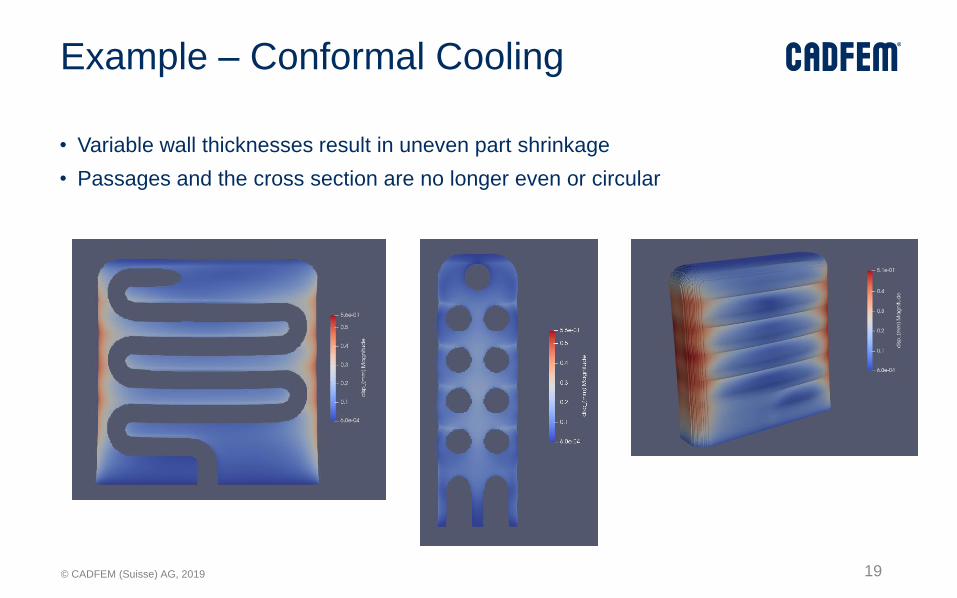
Example – Conformal Cooling
• Variable wall thicknesses result in uneven part shrinkage
• Passages and the cross section are no longer even or circular
19
© CADFEM (Suisse) AG, 2019
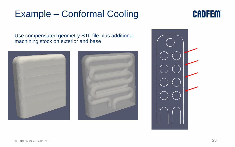
Example – Conformal Cooling
Use compensated geometry STL file plus additional machining stock on exterior and base
20
© CADFEM (Suisse) AG, 2019
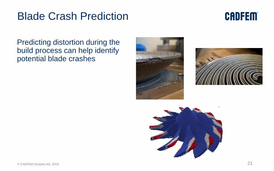
Blade Crash Prediction
Predicting distortion during the build process can help identify potential blade crashes
21

© CADFEM (Suisse) AG, 2019
Example – Support Angle and Distortion
Impeller geometry with a 30° support angle setting
22

© CADFEM (Suisse) AG, 2019
Example – Support Angle and Distortion
Impeller geometry with a 45° support angle setting
23

© CADFEM (Suisse) AG, 2019
Support Optimization
Based on stresses, define support sizing
Courtesy Tim Gornet, University of Louisville
Supports Generated by Magics Optimized Supports
24
© CADFEM (Suisse) AG, 2019
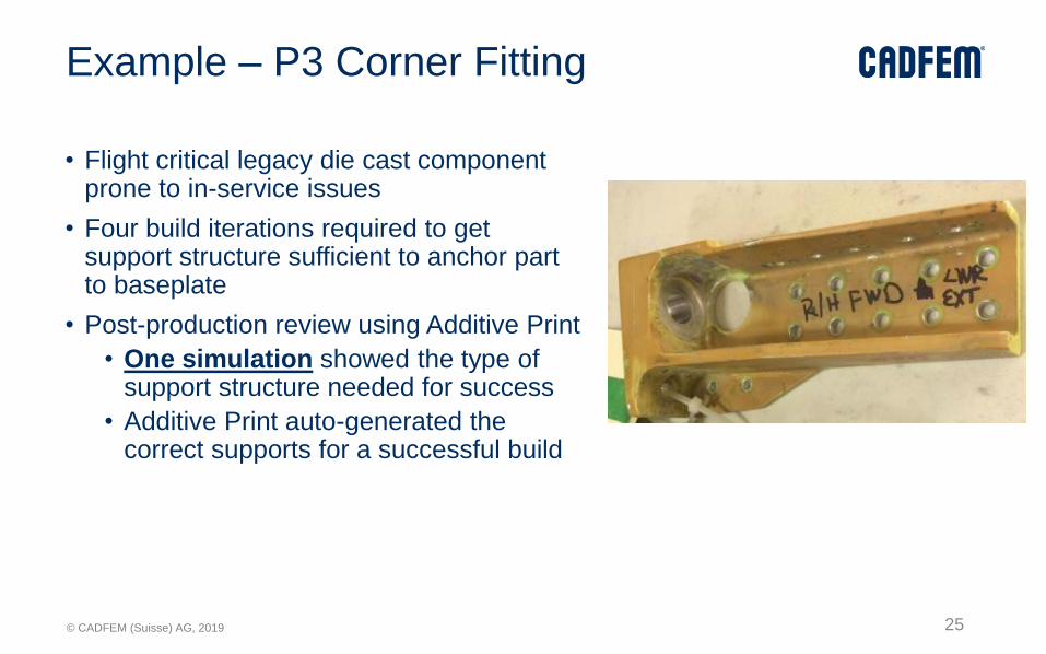
Example – P3 Corner Fitting
• Flight critical legacy die cast component prone to in-service issues
• Four build iterations required to get support structure sufficient to anchor part to baseplate
• Post-production review using Additive Print
• One simulation showed the type of support structure needed for success
• Additive Print auto-generated the correct supports for a successful build
25

© CADFEM (Suisse) AG, 2019
Example – P3 Corner Fitting
Support Failure Prediction
• Prediction of support failure for default supports show excellent correlation to experimental results
• Strengthened supports were also correctly predicted to fail
Default Support
Failure Prediction
Strengthened Support
Failure Prediction
26

© CADFEM (Suisse) AG, 2019
Porosity Defect Predictions (GE P&W Results )
0.00%
5.00%
10.00%
15.00%
20.00%
25.00%
30.00%
850 1050 1250 1450 1650 1850 2050 2250 2450 2650
Po
rosi
ty P
erc
en
tage
Laser Speed (mm/s)
Calculated Porosity (number density) vs. Image Analysis Result (385W)
Simulation Results
Experimental Results
27
© CADFEM (Suisse) AG, 2019
Summary
28

© CADFEM (Suisse) AG, 2019
Machine Parameters
Porosity Prediction
Micro structure analysis
Material Selection
Thermal HistoryTopology Optimization CAD clean up Part Validation
Lattice Optimization
Heat Treatment
Nesting
Support Generation
Support Optimization
Orientation Optimization
Lattice Validation
Intuitive CAD
Re-buildingAdvanced Top Op
Mfg. constraints
5 types AM
Simulation Models
Auto Distortion Compensation
AM Validation
Structural Validation
Design for AM Validation Build SetupProcess
SimulationQualification
Data Acquisition and
Certification Generative Design
29
© CADFEM (Suisse) AG, 2019
Summary
Simulate Before You Print!
30
© CADFEM (Suisse) AG, 2019 31
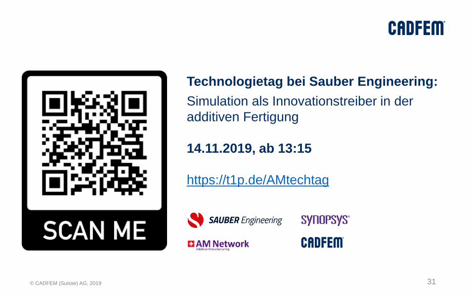
Technologietag bei Sauber Engineering:
Simulation als Innovationstreiber in der
additiven Fertigung
14.11.2019, ab 13:15
https://t1p.de/AMtechtag
© CADFEM (Suisse) AG, 2019
Thank you for your attention!
Dr. sc. (ETH) Manfred Maurer
+41 (0)52 368 01 39
32