ARTICULATING TV WALL MOUNT FOR MOST 22-INCH TO 55 …SUPPORT DE MONTAGE MURAL ARTICULÉ POUR LA...
52
1 ARTICULATING TV WALL MOUNT FOR MOST 22-INCH TO 55-INCH TVS INSTRUCTION MANUAL SUPPORT DE MONTAGE MURAL ARTICULÉ POUR LA PLUPART DES TÉLÉVISEURS DE 22 À 55 POUCES MANUEL D’INSTRUCTIONS TV-GELENK-WANDHALTERUNG FÜR DIE MEISTEN FERNSEHER VON 22 ZOLL (56 CM) BIS 55 ZOLL (140 CM) DIAGONALE ANLEITUNGSHANDBUCH STAFFA DI MONTAGGIO A PARETE CON ARTICOLAZIONE PER LA MAGGIOR PARTE DEI TELEVISORI DA 22-INCH (22 POLLICI) A 55-INCH (55 POLLICI) MANUALE DI ISTRUZIONI SOPORTE DE TV PARA PARED ARTICULADO PARA LA MAYORÍA DE LAS PANTALLAS DE 22 A 55 IN (56 A 140 CM) MANUAL DE INSTRUCCIONES ASIN: B01KBEOL5E
Transcript of ARTICULATING TV WALL MOUNT FOR MOST 22-INCH TO 55 …SUPPORT DE MONTAGE MURAL ARTICULÉ POUR LA...

1
ARTICULATING TV WALL MOUNT FOR MOST 22-INCH TO 55-INCH TVSINSTRUCTION MANUAL
SUPPORT DE MONTAGE MURAL ARTICULÉ POUR LA PLUPART DES TÉLÉVISEURS DE 22 À 55 POUCESMANUEL D’INSTRUCTIONS
TV-GELENK-WANDHALTERUNG FÜR DIE MEISTEN FERNSEHER VON 22 ZOLL (56 CM) BIS 55 ZOLL (140 CM) DIAGONALEANLEITUNGSHANDBUCH
STAFFA DI MONTAGGIO A PARETE CON ARTICOLAZIONE PER LA MAGGIOR PARTE DEI TELEVISORI DA 22-INCH (22 POLLICI) A 55-INCH (55 POLLICI)MANUALE DI ISTRUZIONI
SOPORTE DE TV PARA PARED ARTICULADO PARA LA MAYORÍA DE LAS PANTALLAS DE 22 A 55 IN (56 A 140 CM)MANUAL DE INSTRUCCIONES
ASIN: B01KBEOL5E

2
English Françias Deutsche Italiano Español
WARNINGS 1. Read these instructions before you begin. If at any time you are unclear about the directions and believe you need further assistance, contact 1-866-216-1072. If you are unsure about any part of the process, contact a professional contractor or installer for assistance. Only use the correct tools as noted in these instructions. Improper installation can result in personal injuries and/or damage.
2. At least two people with technical knowledge are required for installing the mount and TV. Keep children and pets away during installation, as they might swallow small parts or packaging resulting in danger of choking/suffocation.
3. Check carefully to ensure that there are no missing or damaged parts. Never use defective parts. To receive replacement or missing part(s) visit amazon.com/gp/help/customer/contact-us or call our Customer Service Department at 1-866-216-1072. Please have the model number, date code, part number(s) and your sales receipt, or other proof of purchase available for reference.
4. Use and install this product only according to the intended use as described within these instructions. Misuse may lead to hazards resulting in potential damage and personal injuries. Do not modify the structure of this product in any way. Manufacturer cannot be liable for direct or indirect damage or personal injuries caused by incorrect mounting, incorrect use, modification to the structure, or incorrect assembly. Keep the instruction manual in a safe place.
5. Refer to the instruction manual provided with the TV you are going to install on this product. It includes additional information for the mount-ing, ventilation and suitable mounting location. Compare the technical data and requirements to make sure that this product is suitable for your TV.
6. Choose the right place to install the wall plate.
SPECIFICATIONSDisplay Size: 22” to 55” Maximum Load: 80 lbs. (36.3 kg)Mounting Pattern: 100x100, 200x100, 200x200, 300x200, 300x300 400x200, 400x300, 400x400 Tilt Range: -5° to 10° down Profile: 2.375” x 16.125” (60mn x 410mm)CAUTION! This product is for indoor use only! Never use the mount outdoors! CAUTION! This product is for private household use only and therefore may not be used in public places like restaurants or hotels.
2 3
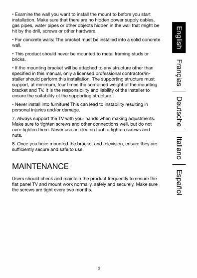
English Françias Deutsche Italiano Español• Examine the wall you want to install the mount to before you start installation. Make sure that there are no hidden power supply cables, gas pipes, water pipes or other objects hidden in the wall that might be hit by the drill, screws or other hardware.
• For concrete walls: The bracket must be installed into a solid concrete wall.
• This product should never be mounted to metal framing studs or bricks.
• If the mounting bracket will be attached to any structure other than specified in this manual, only a licensed professional contractor/in-staller should perform this installation. The supporting structure must support, at minimum, four times the combined weight of the mounting bracket and TV. It is the responsibility and liability of the installer to ensure the suitability of the supporting structure.
• Never install into furniture! This can lead to instability resulting in personal injuries and/or damage.
7. Always support the TV with your hands when making adjustments. Make sure to tighten screws and other connections well, but do not over-tighten them. Never use an electric tool to tighten screws and nuts.
8. Once you have mounted the bracket and television, ensure they are sufficiently secure and safe to use.
MAINTENANCE Users should check and maintain the product frequently to ensure the flat panel TV and mount work normally, safely and securely. Make sure the screws are tight every two months.

4
English Françias Deutsche Italiano EspañolSPÉCIFICATIONSGrandeur de l’écran : 22 po à 55 po Charge maximale : 36,3 kg (80 lbs.) Modèle de montage : 100x100, 200x100, 200x200, 300x200, 300x300 400x200, 400x300, 400x400 Plage verticale : -5° à 10° vers le bas Profil : 60mm x 410mm (2.375” x 16.125”)MISE EN GARDE! Ce produit est destiné uniquement à une utilisation en intérieur! Ne jamais utiliser le support en extérieur! MISE EN GARDE! Ce produit est destiné à un usage domestique privé uniquement et ne peut donc pas être utilisé dans des lieux publics comme les restaurants ou les hôtels.
AVERTISSEMENTS 1. Bien lire le mode d’emploi avant de débuter. Si vous avez des ques-tions ou des doutes au sujet des instructions, communiquez avec le 1 866 216-1072. Si vous n’êtes pas sûr du processus, communiquez avec un professionnel ou un installateur pour assistance. Utilisez uniquement les outils appropriés, comme recommandé dans le mode d’emploi. Une mauvaise installation peut entraîner des blessures et / ou des accidents personnels.
2. Au moins deux personnes ayant des connaissances techniques sont nécessaires pour installer le support du téléviseur. Gardez les enfants et les animaux éloignés lors de l’installation, car ils pourraient avaler de petites pièces ou des morceaux d’emballages, pouvant causer un étouffement et / ou une suffocation.
3. Vérifiez soigneusement qu’il n’y ait pas de pièces manquantes ou endommagées. Ne jamais utiliser de pièces défectueuses. Pour obtenir des pièces de rechange, rendez-vous sur amazon.com/gp/help/custom-er/contact-us ou communiquez avec notre service d’assistance clientèle au 1 866 216-1072. S’il vous plaît, ayez le numéro de modèle, le code de date, le (les) numéro (s) de pièce (s) et votre reçu d’achat ou autre à portée de la main pour référence.
4. Utilisez et installez ce produit uniquement pour l’usage prévu, comme recommandé dans le mode d’emploi. Une mauvaise utilisation peut en-traîner de potentiels dommages et des blessures corporelles. Ne modifier la structure de ce produit en aucune façon. Le fabricant ne peut être tenu responsable des dommages directs, indirects ou corporels causés par un montage/assemblage incorrect, une mauvaise utilisation, ou une modifi-cation de la structure. Gardez le mode d’emploi dans un endroit sûr.
5. Se reporter au mode d’emploi fourni avec le téléviseur que vous allez installer sur ce produit. Celui-ci contient des informations supplé-mentaires pour le montage, la ventilation et l’emplacement du support approprié. Comparez les données et les exigences techniques pour vous assurer que ce produit soit adapté à votre téléviseur.
4 5
English Françias Deutsche Italiano Español6. Choisissez le bon endroit pour installer la plaque murale.
• Assurez-vous que le mur puisse supporter au moins 4 fois le poids de la télévision et du support. Si nécessaire, demandez à un technicien qualifié de renforcer la paroi.
• Examinez le mur sur lequel vous souhaitez installer le support avant de commencer l’installation. Assurez-vous qu’il n’y ait pas de câbles d’alimentation cachés, de conduites de gaz, d’eau ou d’autres objets dans le mur qui pourraient être atteints par la perceuse, les vis ou tout autre matériel.
• Pour les murs à ossature en bois : Ce support est conçu pour être monté sur des goujons de bois de 2 po x 4 po, espacés de 16 po au centre. Les goujons de bois doivent être d’une largeur de 2 po x 4 po, minimum : 1,5 po x 3,5 po (38 mm X 89 mm).
• Pour les murs en béton : Le support doit être installé sur un mur en béton solide.
• Ce produit ne doit jamais être installé sur les montants d’ossatures métalliques ou sur des briques.
• Au cas où le support de montage se joigne à toute structure autre que celle spécifiée dans ce manuel, nous recommandons le service d’un installateur professionnel agréé pour ce faire. La structure de support doit prendre en charge, au minimum, quatre fois le poids combiné du support et du téléviseur. Il est de la responsabilité de l’installateur de s’assurer de la pertinence de la structure où l’appareil sera installé.
• Ne jamais installer à l’intérieur d’un meuble! Cela peut entraîner une instabilité qui pourrait causer des blessures ou des accidents.
7. Toujours soutenir le téléviseur avec vos mains lors des réglages. Assurez-vous de bien serrer les vis et autres connexions sans toutefois les forcer. Ne jamais utiliser d’outil électrique pour serrer les vis et les écrous.
8. Une fois que vous avez monté le support et la télévision, veiller à ce que ces derniers soient suffisamment sécurisés et sûrs à utiliser.
ENTRETIEN
Il est recommandé que les utilisateurs vérifient et révisent fréquem-ment le produit, afin de s’assurer que le téléviseur plat et son support fonctionnent normalement et en toute sécurité. Vérifiez la sûreté des vis tous les deux mois.

6
English Françias Deutsche Italiano EspañolSPEZIFIKATIONENBildschirmgröße: 22 “ bis 55“ Maximalgewicht: 36.3 kg (80 lbs.)Einbauschablone: 100x100, 200x100, 200x200, 300x200, 300x300 400x200, 400x300, 400x400 Neigungsbereich: -5° bis 10° nach unten Profil: 60mn x 410mm (2.375” x 16.125”)ACHTUNG! Dieses Produkt ist nur für den Innengebrauch! Verwenden Sie die Halterung niemals im Freien!ACHTUNG! Dieses Produkt ist für den ausschließlich für den Privathaushalt und kann daher nicht an öffentlichen Orten wie Restaurants oder Hotels verwendet werden.
WARNUNGEN 1. Bevor Sie anfangen, lesen Sie diese Anweisungen. Sollten Ihnen zu irgendeinem Zeitpunkt die Anweisungen unklar sein und Sie glauben, dass Sie weitere Hilfe benötigen, wenden Sie sich an 1-866-216-1072. Sollten Sie sich zu irgendeinem Zeitpunkt bei einem Teil des Ablaufes unsicher sein, kontaktieren Sie eine professionelle Vertragsfirma oder Installateur für weitere Hilfe. Verwenden Sie nur das in dieser Anleitung beschriebene richtige Werkzeug Eine unsachgemäße Installation kann zu persönlichen Verletzungen oder Schäden führen. 2. Zumindest zwei Leute mit technischer Erfahrung sind für die Installa-tion der Halterung und des TVs erforderlich. Halten Sie Kinder und Tiere während der Installation fern, da die Gefahr besteht, dass sie an kleinen Teilen oder Verpackungsmaterial ersticken3. Stellen Sie sorgfältig sicher, dass keine Teile fehlen oder beschädigt sind. Verwenden Sie niemals beschädigte Teile. Um Ersatzteile oder fehlende Teile zu erhalten, suchen Sie amazon.com/gp/help/customer/contact-us auf, oder rufen Sie unsere Kundenserviceabteilung unter 1-866-216-1072 an. Bitte halten Sie Modellnummer, den Datumscode, Teilenummer(n) und Ihre Rechnung oder andere Referenzen falls verfügbar bereit. 4. Nutzen und installieren Sie dieses Produkt nur gemäß der beab-sichtigten Verwendung wie in dieser Anleitung beschrieben. Missbrauch kann zu möglichen Gefahren und daraus resultierenden Schäden und Verletzungen führen. Verändern Sie in keiner Weise die Struktur dieses Produkts. Der Hersteller kann nicht für den direkten oder indirekten Schaden oder persönlichen Verletzungen, verursacht durch die falsche Montage, falschen Gebrauch, Veränderungen an der Struktur, haftbar gemacht werden. Bewahren Sie diese Bedienungsanleitung an einem sicheren Platz auf.5. Beachten Sie die Bedienungsanleitung, die mit dem TV mitgeliefert wurde, wenn Sie mit der Installation dieses Produkts anfangen. Dies bein-haltet zusätzliche Informationen für die Montage, Belüftung und geeignete Montagestelle.
6 7
English Françias Deutsche Italiano Español6. Wählen Sie die geeignete Stelle für die Installation der Wandhalter-ung.
• Stellen Sie sicher, dass die Wand das vierfache Gewicht des Fern-sehers und der Halterung tragen kann. Falls nötig, holen Sie einen qualifizierten Techniker, um die Wand zu verstärken.
• Überprüfen Sie die Wand, auf der Sie die Halterung montieren wollen, vor Installationsbeginn. Stellen Sie sicher, dass sich keine nicht sichtbaren Stromleitungen, Gasleitungen, Wasserleitungen oder andere Objekte in der Wand befinden, die durch den Bohrer, die Schrauben oder andere Hardware beschädigt werden könnten.
• Für Holzständerwände: Diese Halterung ist konzipiert, auf einer 2“ x 4“ Holzständerwand mit einem 16“ Zentrum montiert zu werden. Die Holzständer sollten zumindest 2“ x 4“ sein. 1,5 “x 3,5” (38 mm x 89 mm).
• Für Betonwände: Die Halterung muss an einer massiven Betonwand angebracht werden.
• Das Produkt sollte niemals an einem Metallrahmen oder Ziegeln montiert werden.
• Wenn die Halterung an ein anderes Material als in dieser Anleitung angegeben montiert werden soll, darf diese Montage nur von einem lizenzierten professionellen Vertragspartner / Installateur durchgeführt werden. Die Tragestruktur muss zumindest das vierfache Gewicht der Halterung und des TVs tragen können. Es obliegt der Verantwortung und Haftung des Installateurs, sicherzustellen, dass die Tragestruktur geeignet ist.
• Niemals auf Möbel montieren! Dies kann zu Instabilität führen und zu Verletzungen und oder Schäden führen.
7.Unterstützen Sie den Fernseher immer mit Ihren Händen, wenn Sie Anpassungen vornehmen. Achten Sie darauf, die Schrauben gut festzuziehen und andere Verbindungen gut zu fixieren, aber überdrehen Sie diese nicht. Verwenden Sie niemals ein elektrisches Werkzeug, um die Schrauben und Muttern anzuziehen.
8. Sobald Sie die Halterung und den Fernseher montiert haben, stellen Sie sicher, dass dieser ausreichend sicher für den Gebrauch ist.
MAINTENANCE
Benutzer sollten das Produkt regelmäßig prüfen und pflegen, um sicherzustellen, dass der Flachbildfernseher und die Montage normal, sicher und zuverlässig funktionieren. Achten Sie alle zwei Monate darauf, dass die Schrauben fest angezogen sind.

8
English Françias Deutsche Italiano Español
AVVERTENTE 1. Leggere queste istruzioni prima di iniziare. In caso di dubbi sulle istruzioni e se si necessita di ulteriore assistenza, contattare 1-866-216-1072. Se non si è sicuri di una parte della procedura, contattare una ditta o un installatore professionale per richiedere assistenza. Utilizzare solo gli attrezzi corretti indicati nelle presenti istruzioni. Un’installazione errata potrebbe provocare lesioni personali e/o danni. 2. Per l’installazione del supporto e della TV, sono necessarie almeno due persone con competenze tecniche. Tenere bambini e animali lontano durante l’installazione, poiché potrebbero ingerire piccoli componenti o parti di imballaggio con conseguente pericolo di soffocamento.3. Controllare con attenzione per accertarsi che non vi siano parti danneggiate o mancanti. Non utilizzare mai parti difettose. Per richiedere ricambi o componenti mancanti visitare amazon.com/gp/help/customer/contact-us o contattare il Reparto di Assistenza clienti al numero 1-866-216-1072. Tenere a portata di mano il numero di modello, il codice della data, i part number, la ricevuta e altre prove dell’acquisto. 4. Utilizzare e installare questo prodotto in base all’uso previsto, come descritto nelle presenti istruzioni. L’inosservanza di quanto suddetto potrebbe provocare rischi con potenziali danni e lesioni personali. Non modificare in alcun modo la struttura di questo prodotto. Il produttore non può essere responsabile di lesioni personali o danni diretti o indiretti causati dal montaggio errato, dall’uso non corretto, dalla modifica della struttura o dall’assemblaggio non conforme. Conservare le istruzioni in un luogo sicuro.5. Fare riferimento al manuale di istruzioni fornito con la TV da installare su questo prodotto. Esso include informazioni aggiuntive per il montag-gio, la ventilazione e la posizione di supporto adatta. Confrontare i dati tecnici e i requisiti per accertarsi che questo prodotto sia idoneo per la TV.
SPECIFICHEDimensione schermo: da 22” a 55” Carico massimo: 36.3 kg (80 lbs.)Dima di montaggio: 100x100, 200x100, 200x200, 300x200, 300x300 400x200, 400x300, 400x400 Gamma di inclinazione: da -5° a 10° verso il bassoProfilo: 60mn x 410mm (2.375” x 16.125”)ATTENZIONE! Questo prodotto è solo per uso interno! Non utilizzare mai il supporto all’esterno! ATTENZIONE! Questo prodotto è solo per uso domestico privato, pertanto non può essere utilizzato in locali pubblici come ristoranti o hotel.
8 9
English Françias Deutsche Italiano Español6. Scegliere il luogo corretto per installare la piastra a parete.
• Accertarsi che la parete sia in grado di sostenere almeno 4 volte il peso della TV e del supporto. Se necessario, far rinforzare la parete da un tecnico qualificato.
• Esaminare la parete sulla quale si desidera installare il supporto, prima di iniziare l’installazione. Accertarsi che non vi siano cavi di alimentazione nascosti, tubi del gas o altri oggetti nascosti nel muro che potrebbero essere colpiti dal punzone, dalle viti o altra bulloneria.
• Per le pareti in cartongesso con intelaiatura di legno: Questo supporto è progettato per essere montato su barre di legno 2” X 4” distanziate di 16” al centro. Le barre di legno devono essere 2” x 4”, minimo: 1,5” X 3,5” (38 mm X 89 mm).
• Per pareti in cemento: La staffa deve essere installata in una parete di cemento solido.
• Questo prodotto non deve essere mai montato su intelaiature di metallo o mattoni.
• Se fosse necessario fissare la staffa di supporto a una struttura diversa da quelle specificate nel presente manuale, rivolgersi a una ditta/un installatore professionale per l’installazione. La struttura di supporto deve essere in grado di sostenere, almeno, quattro volte il peso combinato dell staffa di supporto e della TV. È responsabilità dell’installatore accertare l’idoneità della struttura di supporto.
• Non installare mai nei mobili! Ciò potrebbe provocare instabilità con conseguenti lesioni personali e/o danni.
7. Sorreggere sempre la TV con le mani quando si effettuano regolazioni. Accertarsi di serrare correttamente le viti e altri collegamenti, senza serra-re eccessivamente. Non utilizzare attrezzi elettrici per serrare viti e dadi.
8. Una volta montata la staffa e la TV, accertarsi che tutto sia sufficiente-mente saldo e sicuro.
MANUTENZIONE Gli utenti devono frequentemente controllare ed eseguire la manutenzione del prodotto per accertarsi che la TV a schermo piatto e il supporto funzi-onino correttamente, in modo saldo e sicuro. Ogni due mesi, controllare il serraggio delle viti.

10
English Françias Deutsche Italiano Español
ADVERTENCIAS 1. Lea estas instrucciones antes de comenzar. Si, en cualquier momento, tiene dudas sobre las instrucciones y cree que necesita más ayuda, pón-gase en contacto llamando al 1-866-216-1072. Si no está seguro acerca de alguna parte del proceso, póngase en contacto con un contratista profesional o instalador para obtener ayuda. Solo use las herramientas correctas, como se indica en estas instrucciones. Una instalación incor-recta puede dar lugar a lesiones o daños personales. 2. Se requieren al menos dos personas con conocimientos técnicos para la instalación del soporte y del televisor. Mantenga a los niños y a las mascotas lejos durante la instalación, ya que podrían tragarse las piezas pequeñas o el empaque, lo que podría provocar un peligro de atraganta-miento/asfixia.3. Revise cuidadosamente para asegurarse de que no haya piezas faltantes ni dañadas. Nunca utilice piezas defectuosas. Para recibir piezas de repu- esto o piezas faltantes, visite amazon.com/gp/help/customer/contact-us-o llame al Departamento de Servicio al Cliente al 1-866-216-1072. Tenga el número de modelo, el código de fecha, los números de pieza y su recibo de ventas u otro comprobante de compra disponibles como referencia. 4. Use e instale este producto solamente de acuerdo con el uso previsto, como se describe en estas instrucciones. Un uso incorrecto puede dar lugar a riesgos que pueden provocar posibles daños y lesiones perso-nales. No modifique la estructura de este producto de ninguna manera. El fabricante no puede ser responsable de los daños directos o indirectos o lesiones personales causadaspor un montaje incorrecto, un mal uso, una modificación de la estructura o un armado incorrecto. Conserve el manual de instrucciones en un lugar seguro.5. Consulte el manual de instrucciones provisto con el televisor que insta-lará sobre este producto. Incluye información adicional para el montaje, la ven
ESPECIFICACIONESTamaño de la pantalla: De 22 in a 55 in Carga máxima: 36.3 kg (80 lbs.)Patrón de montaje: 100x100, 200x100, 200x200, 300x200, 300x300 400x200, 400x300, 400x400 Rango de inclinación: De -5 ° a 10 ° hacia abajoPerfil: 60mn x 410mm (2.375” x 16.125”)PRECAUCIÓN Este producto está diseñado solamente para usarse en interi-ores. Nunca use el montaje al aire libre. PRECAUCIÓN Este producto está diseñado para uso privado doméstico y, por lo tanto, no puede utilizarse en lugares públicos, como restaurantes y hoteles.

10 11
English Françias Deutsche Italiano Español6. Elija el lugar adecuado para instalar la placa de pared. • Asegúrese de que la pared pueda soportar por lo menos 4 veces el peso del televisor y del soporte. Si es necesario, pida a un técnico calificado que refuerce la pared.•Examine la pared en la que desea instalar el soporte antes de empezar la instalación. Asegúrese de que no haya cables de suministro de energía, tuberías de gas, tuberías de agua u otros objetos ocultos en la pared que podrían sufrir impactos del taladro, de los tornillos o de otras herramien-tas.• Para paredes con montantes de madera: Este soporte está diseñado para montarse en montantes de madera de 2 in x 4 in que están espacia-dos a 16 in en el centro. Los montantes de madera deben ser de 2 in x 4 in, como mínimo: 1.5 in x 3.5 in (38 mm x 89 mm)• Para paredes de concreto: El soporte debe instalarse en una pared de concreto sólido. • Este producto nunca debe montarse en montantes de marco de metal o ladrillos.• Si se acopla el soporte de montaje a cualquier estructura que no sea la especificada en este manual, solo un contratista profesional/instalador autorizado debe realizar esta instalación. La estructura de soporte debe soportar, como mínimo, cuatro veces el peso combinado de la base y del televisor. Es responsabilidad y obligación del instalador garantizar la idoneidad de la estructura de soporte.• Nunca instale el producto en los muebles. Esto puede producir inestabil-idad y causar lesiones o daños personales.7. Siempre sostenga el televisor con las manos al realizar ajustes. Asegúrese de ajustar los tornillos y otras conexiones también, pero no las ajuste demasiado. Nunca utilice una herramienta eléctrica para ajustar tornillos y tuercas.8. Una vez que haya montado el soporte y el televisor, asegúrese de que sean lo suficientemente seguros de usar.
MANTENIMIENTO
Los usuarios deben revisar y dar mantenimiento al producto con frecuencia para asegurar que el televisor de pantalla plana y el soporte funcionen con normalidad y de manera segura. Asegúrese de que los tornillos estén ajusta-dos cada dos meses.
12
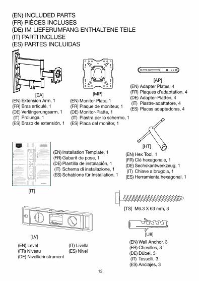
(EN) INCLUDED PARTS(FR) PIÈCES INCLUSES(DE) IM LIEFERUMFANG ENTHALTENE TEILE(IT) PARTI INCLUSE(ES) PARTES INCLUIDAS
Extension Arm, 1Bras articulé, 1Verlängerungsarm, 1Prolunga, 1Brazo de extensión, 1
[EA]Monitor Plate, 1Plaque de moniteur, 1Monitor-Platte, 1Piastra per lo schermo, 1Placa del monitor, 1
[MP](EN)(FR)(DE)(IT)(ES)
(EN)(FR)(DE)(IT)(ES)
(EN)(FR)(DE)(IT)(ES)
Adapter Plates, 4Plaques d’adaptation, 4Adapter-Platten, 4Piastre-adattatore, 4Placas adaptadoras, 4
(EN) Level (IT) Livella (FR) Niveau (ES) Nivel (DE) Nivellierinstrument
[AP]
Hex Tool, 1Clé hexagonale, 1Sechskantwerkzeug, 1Chiave a brugola, 1Herramienta hexagonal, 1
[HT]
Wall Anchor, 3Chevilles, 3Dübel, 3Tasselli, 3Anclajes, 3
[U8][LV]
[IT]
Installation Template, 1Gabarit de pose, 1Plantilla de instalación, 1Schema di installazione, 1Schablone für Installation, 1
6
M5 x 6mm
[TS] M6.3 X 63 mm, 3
A
B
C
(EN) TV Center Line (FR) Axe central de la télévision
(ES) Línea central de la TV(IT) Linea centrale di TV(DE) Mittellinie von der Mitte des TV
(EN) TV Center Line (FR) Axe central de la télévision
(ES) Línea central de la TV(IT) Linea centrale di TV(DE) Mittellinie von der Mitte des TV
400mm x 300mm
MOUNTING TO WOOD STUDS:
Wood studs should be 2" x 4", at minimum: 1.5" X 3.5" (38 mm X 89 mm).Designed to be mounted to 2" X 4" wood studs that are spaced 16" on center.
SEE INSTALLATION GUIDE FOR MASONRY INSTALLATIONS
Using a stud �nder, locate the edges of wall studs and mark studedges with a pencil as shown in the Installation Guide.
Center Installation Template over studs, align drill points“A” , “B”, and “C” with pencil marks. Use a level to ensure thetemplate is straight.
Carefully drill three holes through appropriate points “A” , “B”, and “C”.
Install Lag Bolts through the three holes and tighten securely.
1
2
3
4
POSE SUR MONTANTS EN BOIS :
Montants de bois: 2 po x 4 po. A’au moins : 1,5 po x 3,5 po (38 mm X 89 mm).Conçu pour être posé entre des montants en bois de
2 po x 4 po (38 mm x 89 mm) espacés de 16 po (40,6 cm) entre axes.
VOIR LES INSTRUCTIONS DE POSE SUR MAÇONNERIE DANS LE MANUEL
À l'aide d'un détecteur de montant, déterminez l'emplacementdes bords du montant et marquez-les au crayon comme indiquédans le Guide de pose.
Centrez le gabarit de pose sur le montant et alignez les pointsde perçage « A », « B », et « C » sur les repères au crayon.Utilisez un niveau pour véri�er que le gabarit est droit.
Percez avec soin à travers les points « A », « B », et « C »qui conviennent.
Posez des tire-fond dans les trois trous et serrez-les fermement.
1
2
3
4
INSTALLAZIONE SU MONTANTE DI LEGNO:
I montanti di legno dovrebbe essere 2" x 4", al minimo: 1.5" x 3.5" (38 mm x 89 mm).Inteso per essere montato a 40,5 cm dal centro di montanti di legno da 5x10.
FARE RIFERIMENTO ALLA GUIDA ALL'INSTALLAZIONENEL CASO DI INSTALLAZIONI SU LEGNO
Con l'ausilio di un rilevatore, individuare i punti estremi laterali delmontante e contrassegnare tali punti con una matita, come indicatonella guida all'installazione.
Centrare lo Schema di installazione sul montante, allineare i punti datrapanare “A”, “B”, e “C” e i segni in matita. Con una livella veri�careche lo schema sia parallelo al suolo.
Con attenzione, trapanare tre fori attraverso i punti “A”, “B”, e “C”.
Inserire le viti attraverso i tre fori e serrarle con cura.
1
2
34
BEFESTIGUNG EINES HOLZBOLZENS:
Einem holzpfosten sollten 2" X 4" sein, an minimum: 1,5" X 3,5" (38 mm X 89 mm).Ausführung zum Einbau 40,64 cm mittig zwischen zwei 2" x 4" Bolzen aus Holz.
SIEHE INSTALLATIONSLEITFADEN FÜR INSTALLATIONEN IN GEMÄUER
Finden Sie die Ecken des Wandbolzens mit einem Bolzensucher undmarkieren Sie die Bolzenkanten mit einem Bleistift wie im Installations-Leitfaden angegeben.
Richten Sie die Installationsschablone mittig über dem Bolzen aus, �uchtenSie die Bohrpunkte „A“ „B“ und „C“ mit Bleistiftmarkierungen aus.Benutzen Sie ein Nivelliergerät, damit sichergestellt wird, dass die Schablonegerade ausgerichtet ist.
Bohren Sie vorsichtig drei Löcher durch die entsprechendenPunkte „A“ „B“ und „C“.
Führen Sie die Ankerschraube durch die drei Löcher ein und ziehen Sie sie fest.
1
2
3
4
(EN
) Out
er E
dge
of S
tud
(FR)
Bor
d ex
térie
ur d
u m
onta
nt(D
E) Ä
ußer
e Ka
nte
des
Bolz
ens
(IT) B
ordo
est
erno
del
mon
tant
e(E
S) B
orde
ext
erno
del
mon
tant
e
(EN
) Out
er E
dge
of S
tud
(FR)
Bor
d ex
térie
ur d
u m
onta
nt(D
E) Ä
ußer
e Ka
nte
des
Bolz
ens
(IT) B
ordo
est
erno
del
mon
tant
e(E
S) B
orde
ext
erno
del
mon
tant
e (EN) INSTALLATION TEMPLATE(FR) GABARIT DE POSE
(DE) INSTALLATIONSSCHABLONE(IT) SCHEMA DI INSTALLAZIONE
(ES) PLANTILLA DE INSTALACIÓN
(EN)
(FR)
INSTALACIÓN EN MONTANTES DE MADERA:Los montantes de madera deben ser 2" X 4", un mínimo de 1,5" X 3,5" (38 mm X 89 mm).
Diseñado para usar montado sobre montantes de madera de2" x 4" (2,5 x 5 cm) separados por 16" (2,5 cm) desde el centro de cada uno.
VER EL MANUAL DE INSTALACIÓN PARA INSTALACIONES DE MAMPOSTERÍA
Con un localizador de montantes, localice los bordes del montantede pared y márquelos con un lápiz como se muestra en el manualde instalación.
Centre la plantilla de instalación sobre el montante, alinee los puntosde perforación “A”, “B” , y “C” con las marcas de lápiz. Utilice un nivelpara asegurarse de que la plantilla esté derecha.
Haga cuidadosamente tres perforaciones en los puntosapropiados “A”, “B” y “C”.
Instale tirafondos en las tres perforaciones y ajuste �rmemente.
1
2
3
4
ASIN B01KBEOL5E
(ES)
(IT)
(EN
) Che
ck L
evel
Lin
e
(F
R) L
igne
de
Niv
eau
(IT) V
erifi
care
che
lo s
chem
a si
a pa
ralle
lo a
l suo
lo
(E
S) R
evis
e la
líne
a de
niv
el
(DE)
Hor
izon
tale
Aus
richt
ung
prüf
en
(DE)
(EN
) Out
er E
dge
of S
tud
(FR)
Bor
d ex
térie
ur d
u m
onta
nt(D
E) Ä
ußer
e Ka
nte
des
Bolz
ens
(IT) B
ordo
est
erno
del
mon
tant
e(E
S) B
orde
ext
erno
del
mon
tant
e
(EN
) Out
er E
dge
of S
tud
(FR)
Bor
d ex
térie
ur d
u m
onta
nt(D
E) Ä
ußer
e Ka
nte
des
Bolz
ens
(IT) B
ordo
est
erno
del
mon
tant
e(E
S) B
orde
ext
erno
del
mon
tant
e
100mm x 100mm 200mm x 100mm 200mm x 200mm
300mm x 200mm 300mm x 300mm 400mm x 200mm 400mm x 400mm
(EN)(FR)(DE)(IT)(ES)
(EN)(FR)(DE)(IT)(ES)
(EN)(FR)(DE)(IT)(ES)

12 13
(EN) INCLUDED PARTS(FR) PIÈCES INCLUSES(DE) IM LIEFERUMFANG ENTHALTENE TEILE(IT) PARTI INCLUSE(ES) PARTES INCLUIDAS
INCLUDED PARTS PIÈCES INCLUSES PARTES INCLUIDAS
PARTI INCLUSE ПОСТАВЛЯЕМЫЙКОМПЛЕКТ
IM LIEFERUMFANGENTHALTENE TEILE
[A] M4 x 12mm, 4 [C] M4 x 30mm, 4
[J] M6 x 14mm, 4 [L] M6 x 35mm, 4
[M] M8 x 20mm, 4 [OS] M8 x 38mm, 4
[BE] M8 x 10mm, 8
[E] M4, 4 [P] M6/M8, 4
[R] M4, 6 [S] M6/M8, 4

14
(EN) NECESSARY TOOLS(FR) OUTILLAGE NÉCESSAIRE(DE) ERFORDERLICHE WERKZEUGE(IT) ATTREZZI NECESSARI(ES) HERRAMIENTAS NECESARIAS
NECESSARYTOOLS
OUTILLAGENÉCESSAIRE
HERRAMIENTASNECESARIAS
ATTREZZINECESSARI
НЕОБХОДИМЫЕИНСТРУМЕНТЫ
ERFORDERLICHEWERKZEUGE
(EN) Phillips-head Screwdriver(FR) Tournevis à tête Phillips(DE) Kreuzschlitzschraubenzieher(IT) Cacciavite Phillips(ES) Destornillador philips (cruz)
(EN) Ratchet Set(FR) Clé à cliquet à douilles(DE) Schaltklinke Hilfsmittel(IT) Strumento Del Cricco(ES) Equipo de trinquete
(EN) Masking Tape(FR) Ruban de masquage(DE) Abdeckband(IT) Nastro adesivo(ES) Cinta de enmascarar
(EN) Stud Finder(FR) Détecteur de montant(DE) Bolzenfinder(IT) Rilevatore di montanti(ES) Localizador de montantes
(EN) Drill Bit: Wood: 5/32" (4mm), Masonry: 5/16" (8mm)(FR) Foret Bois : 5/32 po (4 mm), Maçonnerie : 5/16 po (8 mm)(DE) Bohrerspitze, Holz: 4 mm; Mauerwerk: 8 mm(IT) Punte trapano da legno: 4 mm; da muro: 8 mm(ES) Broca para madera: 5/32" (4 mm), para mampostería: 5/16" (8 mm)
(EN) Drill(FR) Perceuse(DE) Bohrer(IT) Trapano(ES) Taladro
(EN) Tape Measure(FR) Ruban à mesurer(DE) Messband(IT) Metro(ES)] Cinta métrica
(EN) Pencil(FR) Crayon(DE) Bleistift(IT) Matita(ES) Lápiz
14 15
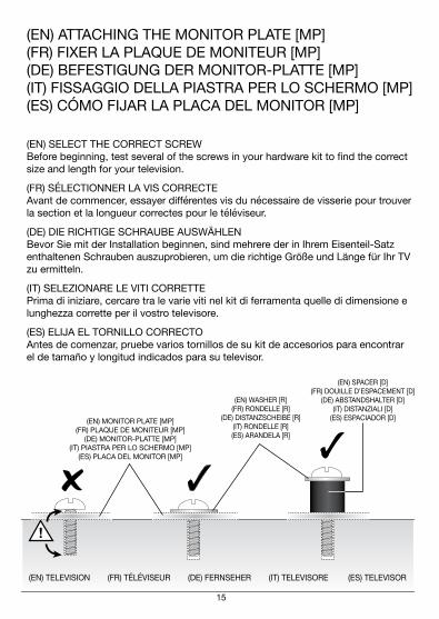
(EN) ATTACHING THE MONITOR PLATE [MP](FR) FIXER LA PLAQUE DE MONITEUR [MP](DE) BEFESTIGUNG DER MONITOR-PLATTE [MP](IT) FISSAGGIO DELLA PIASTRA PER LO SCHERMO [MP](ES) CÓMO FIJAR LA PLACA DEL MONITOR [MP]
(EN) SELECT THE CORRECT SCREW Before beginning, test several of the screws in your hardware kit to find the correct size and length for your television.
(FR) SÉLECTIONNER LA VIS CORRECTE Avant de commencer, essayer différentes vis du nécessaire de visserie pour trouver la section et la longueur correctes pour le téléviseur.
(DE) DIE RICHTIGE SCHRAUBE AUSWÄHLEN Bevor Sie mit der Installation beginnen, sind mehrere der in Ihrem Eisenteil-Satz enthaltenen Schrauben auszuprobieren, um die richtige Größe und Länge für Ihr TV zu ermitteln.
(IT) SELEZIONARE LE VITI CORRETTE Prima di iniziare, cercare tra le varie viti nel kit di ferramenta quelle di dimensione e lunghezza corrette per il vostro televisore.
(ES) ELIJA EL TORNILLO CORRECTO Antes de comenzar, pruebe varios tornillos de su kit de accesorios para encontrar el de tamaño y longitud indicados para su televisor.
(EN) TELEVISION (FR) TÉLÉVISEUR (DE) FERNSEHER (IT) TELEVISORE (ES) TELEVISOR
(EN) MONITOR PLATE [MP](FR) PLAQUE DE MONITEUR [MP]
(DE) MONITOR-PLATTE [MP](IT) PIASTRA PER LO SCHERMO [MP]
(ES) PLACA DEL MONITOR [MP]
(EN) WASHER [R](FR) RONDELLE [R]
(DE) DISTANZSCHEIBE [R](IT) RONDELLE [R](ES) ARANDELA [R]
(EN) SPACER [D](FR) DOUILLE D’ESPACEMENT [D]
(DE) ABSTANDSHALTER [D](IT) DISTANZIALI [D]
(ES) ESPACIADOR [D]

16
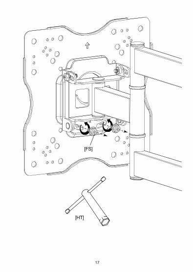
(EN) REMOVE THE SECURITY SCREWS (FS)The Monitor Plate (MP) was shipped pre-installed to the Extension Arm (EA). Before you begin, remove the two Security Screws (FS) as shown in and separate the two components.Do not throw out the security screws.
(FR) ENLEVER LES VIS DE SÉCURITÉ (FS)La plaque de moniteur (MP) est livrée attachée au bras articulé (EA). Avant de com-mencer, enlever les deux vis de sécurité (FS) comme sur l’illustration et séparer les deux éléments.Ne pas jeter les vis de sécurité.
{DE) NEHMEN SIE DIE SICHERUNGSSCHRAUBEN AB (FS)Die Monitorplatte (MP) ist bereits am Verlängerungsarm (EA) vorinstalliert im Lieferumfang mit inbegriffen. Bevor Sie anfangen, bitte die beiden Sicherungss-chrauben (FS) wie dargestellt entfernen und die beiden Bestandteile trennen. Bitte die Sicherheitsschrauben nicht wegwerfen.
(IT) RIMUOVERE LE VITI DI SICUREZZA (FS)La piastra per lo schermo (MP) viene spedita pre-installata sulla prolunga (EA). Prima di iniziare, rimuovere le due viti di sicurezza (FS), come illustrato, e separare i due componenti.Non gettare le viti di sicurezza.
(ES) QUITE LOS TORNILLOS DE SEGURIDAD (FS)La placa para la pantalla (MP) se envía ya instalada en el brazo de extensión (EA). Antes de comenzar, retire los dos tornillos de seguridad (FS) tal como se muestra y separe las dos piezas.No deseche los tornillos de seguridad.
16 17
[HT]
[FS]

18
(EN) DECIDE IF ADAPTER PLATES [AP] ARE NECESSARY Compare to the mounting holes on the back of your television.
(FR) DÉCIDER SI DES PLAQUES D’ADAPTATION [AP] SON NÉCESSAIRES Comparer aux trous de fixation au dos du téléviseur.
(DE) ENTSCHEIDEN SIE SICH, OB ADAPTER-PLATTEN [AP] ERFORDERLICH SIND Vergleichen Sie sie mit den Montagelöchern auf der Rückseite Ihres Fernsehers.
(IT) DECIDERE SE LE PIASTRE-ADATTORE [AP] SONO NECESSARIE Verificare la corrispondenza tra la posizione dei fori sul retro del televisore e il supporto stesso.
(ES) DETERMINE SI NECESITA LAS PLACAS ADAPTADORAS [AP] Compare los orificios de montaje en la parte trasera de su televisor.
1
2
3
4
5
6
7
100mm x 100mm200mm x 100mm
400mm x 300mm
200mm x 200mm300mm x 200mm300mm x 300mm400mm x 200mm
8 400mm x 400mm

18 19
(EN) IF USING THE ADAPTER PLATES [AP]: Attach the Adapter Plates [AP] to the Monitor Plate [MP] using eight M8 x 10mm Screws [BE].
(FR) SI LES PLAQUES D’ADAPTATION [AP] SONT UTILISÉES : Fixer les plaques d’adaptation [AP] à la plaque de moniteur [MP] à l’aide de huit vis M8 x 10mm [BE].
(DE) FALLS SIE ADAPTER- PLATTEN [AP] VERWENDEN: Befestigen Sie die Adapter-Platten [AP] an der Monitor-Platte [MP] mit acht M8 x 10mm schrauben [BE].
(IT) SE LE PIASTRE-ADATTORE [AP] SONO NECESSARIE: Fissare le piastre-adattatore [AP] alla piastra per lo schermo [MP] utilizzando otto viti M8 x 10mm [BE].
(ES) SI USA LAS PLACAS ADAPTADORAS [AP] Una las placas adaptadoras [AP] a la placa del monitor [MP] utilizando ocho tornillos M8 x 10 mm [BE].
[BE]
[AP]
[MP]
20
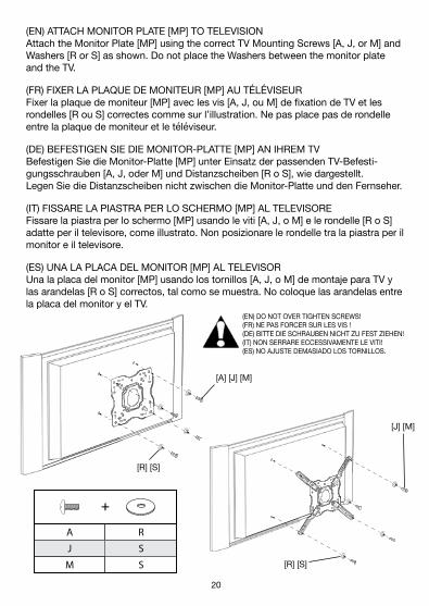
(EN) ATTACH MONITOR PLATE [MP] TO TELEVISION Attach the Monitor Plate [MP] using the correct TV Mounting Screws [A, J, or M] and Washers [R or S] as shown. Do not place the Washers between the monitor plate and the TV.
(FR) FIXER LA PLAQUE DE MONITEUR [MP] AU TÉLÉVISEUR Fixer la plaque de moniteur [MP] avec les vis [A, J, ou M] de fixation de TV et les rondelles [R ou S] correctes comme sur l’illustration. Ne pas place pas de rondelle entre la plaque de moniteur et le téléviseur.
(DE) BEFESTIGEN SIE DIE MONITOR-PLATTE [MP] AN IHREM TV Befestigen Sie die Monitor-Platte [MP] unter Einsatz der passenden TV-Befesti-gungsschrauben [A, J, oder M] und Distanzscheiben [R o S], wie dargestellt. Legen Sie die Distanzscheiben nicht zwischen die Monitor-Platte und den Fernseher.
(IT) FISSARE LA PIASTRA PER LO SCHERMO [MP] AL TELEVISORE Fissare la piastra per lo schermo [MP] usando le viti [A, J, o M] e le rondelle [R o S] adatte per il televisore, come illustrato. Non posizionare le rondelle tra la piastra per il monitor e il televisore.
(ES) UNA LA PLACA DEL MONITOR [MP] AL TELEVISOR Una la placa del monitor [MP] usando los tornillos [A, J, o M] de montaje para TV y las arandelas [R o S] correctos, tal como se muestra. No coloque las arandelas entre la placa del monitor y el TV.
(EN) DO NOT OVER TIGHTEN SCREWS!(FR) NE PAS FORCER SUR LES VIS !(DE) BITTE DIE SCHRAUBEN NICHT ZU FEST ZIEHEN!(IT) NON SERRARE ECCESSIVAMENTE LE VITI!(ES) NO AJUSTE DEMASIADO LOS TORNILLOS.
[R] [S]
[R] [S]
[A] [J] [M]
[J] [M]
A
J
M
R
S
S
C R
L
OS
S
S
E
P
P
20 21
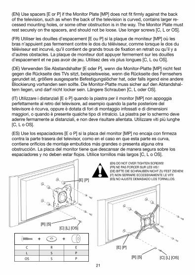
(EN) Use spacers [E or P] if the Monitor Plate [MP] does not fit firmly against the back of the television, such as when the back of the television is curved, contains larger re-cessed mounting holes, or some other obstruction is in the way. The Monitor Plate must rest securely on the spacers, and should not be loose. Use longer screws [C, L or OS].
(FR) Utiliser les douilles d’espacement [E ou P] si la plaque de moniteur [MP] où les bras n’appuient pas fermement contre le dos du téléviseur, comme lorsque le dos du téléviseur est incurvé, qu’il contient de grands trous de fixation en retrait ou qu’il y a d’autres obstacles. La plaque de moniteur doit appuyer fermement sur les douilles d’espacement et ne pas avoir de jeu. Utilisez des vis plus longues [C, L ou OS].
(DE) Verwenden Sie Abstandshalter [E oder P], wenn die Monitor-Platte [MP] nicht fest gegen die Rückseite des TVs sitzt, beispielsweise, wenn die Rückseite des Fernsehers gerundet ist, größere ausgesparte Befestigungslöcher hat, oder falls irgend eine andere Blockierung vorhanden sein sollte. Die Monitor-Platte muss sicher auf den Abtandshal-tern liegen, und darf nicht locker sein. Längere Schrauben [C, L oder OS].
(IT) Utilizzare i distanziali [E o P] quando la piastra per il monitor [MP] non appoggia perfettamente al retro del televisore, ad esempio quando la parte posteriore del televisore è ricurva, oppure è dotata di fori di montaggio infossati e di dimensioni maggiori, o quando è presente qualche tipo di intralcio. La piastra per lo schermo deve aderire fermamente ai distanziali, e non deve risultare allentata. Utilizzare viti più lunghe [C, L o OS].
(ES) Use los espaciadores [E o P] si la placa del monitor [MP] no encaja con firmeza contra la parte trasera del televisor, como en el caso en que esta parte es curva, contiene orificios de montaje embutidos más grandes o presenta alguna otra obstrucción. La placa del monitor tiene que descansar de manera segura sobre los espaciadores y no deben estar flojos. Utilice tornillos más largos [C, L o OS].
[C] [L] [OS]
[C] [L] [OS]
[E] [P]
[E] [P]
[R] [S]
[R] [S]
A
J
M
R
S
S
C R
L
OS
S
S
E
P
P
(EN) DO NOT OVER TIGHTEN SCREWS!(FR) NE PAS FORCER SUR LES VIS !(DE) BITTE DIE SCHRAUBEN NICHT ZU FEST ZIEHEN!(IT) NON SERRARE ECCESSIVAMENTE LE VITI!(ES) NO AJUSTE DEMASIADO LOS TORNILLOS.

22
(EN) INSTALLING THE WALL MOUNT IN WOOD(FR) POSER LE SUPPORT MURAL SUR DU BOIS(DE) INSTALLATION DER WANDBEFESTIGUNG IN HOLZ(IT) INSTALLAZIONE DEL SUPPORTO A PARETE SU LEGNO(ES) CÓMO INSTALAR EL SOPORTE DE PARED EN MADERA
(EN) FIND THE WOOD STUD Using a stud finder, find the exact location of the stud to which you want to attach the wall mount. Mark the right and left side to determine the center of the stud. Wood studs should be 2" x 4", at minimum: 1.5" X 3.5" (38 mm x 89 mm).
(FR) TROUVER LE MONTANT EN BOIS À l’aide d’un détecteur de montant, trouver l’emplacement exact du montant sur lequel doit être attaché le support mural. Marquer les bords gauche et droit pour déterminer le centre du montant. Montants de bois: 2 po x 4 po. A’au moins : 1,5 po x 3,5 po (38 mm x 89 mm).
(DE) FINDEN SIE DEN HOLZBOLZEN Mit einem Bolzenfinder können Sie den genauen Ort des Bolzens finden, an dem Sie die Wandbefestigung befestigen wollen. Markieren Sie die rechte sowie auch linke Seite, um die Mitte des Bolzens bestimmen zu können. Einem holzpfosten sollten 2" x 4" sein, an minimum: 1,5" x 3,5" (38 mm x 89 mm).
(IT) INDIVIDUARE IL MONTANTE DI LEGNO Con l’ausilio di un rilevatore, individuare la posizione esatta del montante al quale si intende fissare il supporto a parete. Contrassegnare gli estremi sinistro e destro del montante per determinarne il punto centrale. I montanti di legno dovrebbe essere 2" x 4", al minimo: 1.5" x 3.5" (38 mm x 89 mm).
(ES) ENCUENTRE EL MONTANTE DE MADERA Utilizando un localizador de montantes, encuentre la ubicación exacta del montante sobre el que desea fijar el soporte de pared. Marque los lados derecho e izquierdo para determinar el centro del montante. Los montantes de madera deben ser 2" x 4", un mínimo de 1,5" x 3,5" (38 mm x 89 mm).

22 23
(EN) DETERMINE HEIGHT LOCATION OF TELEVISION Measure the distance from the bracket holes to the top and bottom of the TV to determine the center mounting position. Measure from the floor up, and make small marks on the wall to help you determine the desired TV height. Using a level, line up the Installation Template [IT] with your pencil markings and tape it into place.
(FR) DÉTERMINER L’EMPLACEMENT EN HAUTEUR DU TÉLÉVISEUR Mesurer la distance des mesurer la distance entre les trous du support et le haut et le bas du téléviseur pour déterminer la position de pose centrale. Mesurer la hauteur depuis le sol et tracer de petits repères sur le mur pour marquer la hauteur souhaitée pour le téléviseur. À l’aide d’un niveau, aligner le gabarit de pose [IT] sur les marquages et l’attacher avec du ruban adhésif.
(DE) BESTIMMEN SIE DIE STELLE DER HÖHE DES FERNSEHERS Messen Sie den Abstand von den Trägerlöchern zum oberen und unteren Teil des TVs, um die Mitte festzulegen. Messen Sie vom Fußboden nach oben, und markieren Sie die Wand mit kleinen Bleistiftmarkierungen, um die gewünschte Höhe des Fernsehers bestimmen zu können. Mit einem Nivellierinstrument wird die Installationsschablone [IT] mit Ihren Bleistiftmarkierungen ausgerichtet und mit dem Abdeckband an der richtigen Stelle befestigt.
(IT) DETERMINARE LA POSIZIONE IN ALTEZZA DEL TELEVISORE Per determinare la posizione centrale di montaggio, misurare la distanza dai fori dei sostegni alla parte superiore e quella inferiore del televisore. Misurare partendo dal pavimento, e fare un segno sul muro per indicare l’altezza desiderata. Con l’ausilio di una livella, allineare lo schema di installazione [IT] al segno sul muro e fissarlo con nastro adesivo.
(ES) DETERMINE LA ALTURA EN LA QUE COLOCARÁ EL TELEVISOR Para determinar el centro de la posición de montaje mida la distancia desde los orificios del soporte hasta las partes superior y trasera del televisor. Mida desde el piso y haga pequeñas marcas sobre la pared para ayudarse a determinar la altura deseada para el TV. Use un nivel para alinear la plantilla de instalación [IT] con las marcas del lápiz y sujete con cinta adhesiva en el lugar.

24
[IT]
[LV]
TV
16" (406 MM)
(EN) Height to bottom of TV(FR) Hauteur jusqu’au bas du téléviseur(DE) Höhe zum unteren Teil des TVs(IT) Altezza alla parte inferiore del televisore(SP) Altura hasta la parte inferior del TV
24 25
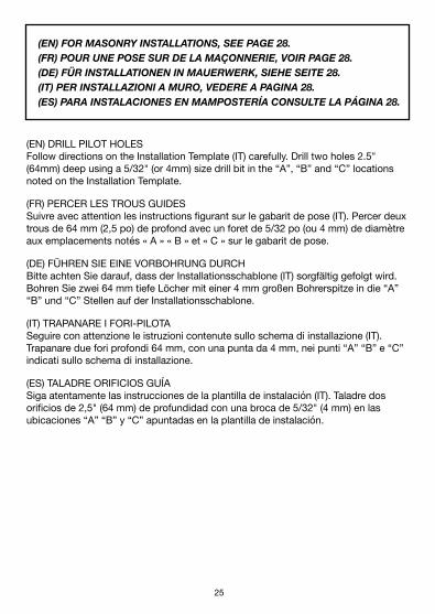
(EN) FOR MASONRY INSTALLATIONS, SEE PAGE 28.(FR) POUR UNE POSE SUR DE LA MAÇONNERIE, VOIR PAGE 28.(DE) FÜR INSTALLATIONEN IN MAUERWERK, SIEHE SEITE 28.(IT) PER INSTALLAZIONI A MURO, VEDERE A PAGINA 28.(ES) PARA INSTALACIONES EN MAMPOSTERÍA CONSULTE LA PÁGINA 28.
(EN) DRILL PILOT HOLES Follow directions on the Installation Template (IT) carefully. Drill two holes 2.5" (64mm) deep using a 5/32" (or 4mm) size drill bit in the “A”, “B” and “C” locations noted on the Installation Template.
(FR) PERCER LES TROUS GUIDES Suivre avec attention les instructions figurant sur le gabarit de pose (IT). Percer deux trous de 64 mm (2,5 po) de profond avec un foret de 5/32 po (ou 4 mm) de diamètre aux emplacements notés « A » « B » et « C » sur le gabarit de pose.
(DE) FÜHREN SIE EINE VORBOHRUNG DURCH Bitte achten Sie darauf, dass der Installationsschablone (IT) sorgfältig gefolgt wird. Bohren Sie zwei 64 mm tiefe Löcher mit einer 4 mm großen Bohrerspitze in die “A” “B” und “C” Stellen auf der Installationsschablone.
(IT) TRAPANARE I FORI-PILOTA Seguire con attenzione le istruzioni contenute sullo schema di installazione (IT). Trapanare due fori profondi 64 mm, con una punta da 4 mm, nei punti “A” “B” e “C” indicati sullo schema di installazione.
(ES) TALADRE ORIFICIOS GUÍA Siga atentamente las instrucciones de la plantilla de instalación (IT). Taladre dos orificios de 2,5" (64 mm) de profundidad con una broca de 5/32" (4 mm) en las ubicaciones “A” “B” y “C” apuntadas en la plantilla de instalación.

26
B
A
5/32" (4 MM)
2-1/2" (64 MM)
A
B
C
(EN) TV Center Line (FR) Axe central de la télévision
(ES) Línea central de la TV(IT) Linea centrale di TV(DE) Mittellinie von der Mitte des TV
(EN) TV Center Line (FR) Axe central de la télévision
(ES) Línea central de la TV(IT) Linea centrale di TV(DE) Mittellinie von der Mitte des TV
400mm x 300mm
MOUNTING TO WOOD STUDS:
Wood studs should be 2" x 4", at minimum: 1.5" X 3.5" (38 mm X 89 mm).Designed to be mounted to 2" X 4" wood studs that are spaced 16" on center.
SEE INSTALLATION GUIDE FOR MASONRY INSTALLATIONS
Using a stud �nder, locate the edges of wall studs and mark studedges with a pencil as shown in the Installation Guide.
Center Installation Template over studs, align drill points“A” , “B”, and “C” with pencil marks. Use a level to ensure thetemplate is straight.
Carefully drill three holes through appropriate points “A” , “B”, and “C”.
Install Lag Bolts through the three holes and tighten securely.
1
2
3
4
POSE SUR MONTANTS EN BOIS :
Montants de bois: 2 po x 4 po. A’au moins : 1,5 po x 3,5 po (38 mm X 89 mm).Conçu pour être posé entre des montants en bois de
2 po x 4 po (38 mm x 89 mm) espacés de 16 po (40,6 cm) entre axes.
VOIR LES INSTRUCTIONS DE POSE SUR MAÇONNERIE DANS LE MANUEL
À l'aide d'un détecteur de montant, déterminez l'emplacementdes bords du montant et marquez-les au crayon comme indiquédans le Guide de pose.
Centrez le gabarit de pose sur le montant et alignez les pointsde perçage « A », « B », et « C » sur les repères au crayon.Utilisez un niveau pour véri�er que le gabarit est droit.
Percez avec soin à travers les points « A », « B », et « C »qui conviennent.
Posez des tire-fond dans les trois trous et serrez-les fermement.
1
2
3
4
INSTALLAZIONE SU MONTANTE DI LEGNO:
I montanti di legno dovrebbe essere 2" x 4", al minimo: 1.5" x 3.5" (38 mm x 89 mm).Inteso per essere montato a 40,5 cm dal centro di montanti di legno da 5x10.
FARE RIFERIMENTO ALLA GUIDA ALL'INSTALLAZIONENEL CASO DI INSTALLAZIONI SU LEGNO
Con l'ausilio di un rilevatore, individuare i punti estremi laterali delmontante e contrassegnare tali punti con una matita, come indicatonella guida all'installazione.
Centrare lo Schema di installazione sul montante, allineare i punti datrapanare “A”, “B”, e “C” e i segni in matita. Con una livella veri�careche lo schema sia parallelo al suolo.
Con attenzione, trapanare tre fori attraverso i punti “A”, “B”, e “C”.
Inserire le viti attraverso i tre fori e serrarle con cura.
1
2
34
BEFESTIGUNG EINES HOLZBOLZENS:
Einem holzpfosten sollten 2" X 4" sein, an minimum: 1,5" X 3,5" (38 mm X 89 mm).Ausführung zum Einbau 40,64 cm mittig zwischen zwei 2" x 4" Bolzen aus Holz.
SIEHE INSTALLATIONSLEITFADEN FÜR INSTALLATIONEN IN GEMÄUER
Finden Sie die Ecken des Wandbolzens mit einem Bolzensucher undmarkieren Sie die Bolzenkanten mit einem Bleistift wie im Installations-Leitfaden angegeben.
Richten Sie die Installationsschablone mittig über dem Bolzen aus, �uchtenSie die Bohrpunkte „A“ „B“ und „C“ mit Bleistiftmarkierungen aus.Benutzen Sie ein Nivelliergerät, damit sichergestellt wird, dass die Schablonegerade ausgerichtet ist.
Bohren Sie vorsichtig drei Löcher durch die entsprechendenPunkte „A“ „B“ und „C“.
Führen Sie die Ankerschraube durch die drei Löcher ein und ziehen Sie sie fest.
1
2
3
4
(EN
) Out
er E
dge
of S
tud
(FR)
Bor
d ex
térie
ur d
u m
onta
nt(D
E) Ä
ußer
e Ka
nte
des
Bolz
ens
(IT) B
ordo
est
erno
del
mon
tant
e(E
S) B
orde
ext
erno
del
mon
tant
e
(EN
) Out
er E
dge
of S
tud
(FR)
Bor
d ex
térie
ur d
u m
onta
nt(D
E) Ä
ußer
e Ka
nte
des
Bolz
ens
(IT) B
ordo
est
erno
del
mon
tant
e(E
S) B
orde
ext
erno
del
mon
tant
e (EN) INSTALLATION TEMPLATE(FR) GABARIT DE POSE
(DE) INSTALLATIONSSCHABLONE(IT) SCHEMA DI INSTALLAZIONE
(ES) PLANTILLA DE INSTALACIÓN
(EN)
(FR)
INSTALACIÓN EN MONTANTES DE MADERA:Los montantes de madera deben ser 2" X 4", un mínimo de 1,5" X 3,5" (38 mm X 89 mm).
Diseñado para usar montado sobre montantes de madera de2" x 4" (2,5 x 5 cm) separados por 16" (2,5 cm) desde el centro de cada uno.
VER EL MANUAL DE INSTALACIÓN PARA INSTALACIONES DE MAMPOSTERÍA
Con un localizador de montantes, localice los bordes del montantede pared y márquelos con un lápiz como se muestra en el manualde instalación.
Centre la plantilla de instalación sobre el montante, alinee los puntosde perforación “A”, “B” , y “C” con las marcas de lápiz. Utilice un nivelpara asegurarse de que la plantilla esté derecha.
Haga cuidadosamente tres perforaciones en los puntosapropiados “A”, “B” y “C”.
Instale tirafondos en las tres perforaciones y ajuste �rmemente.
1
2
3
4
ASIN B01KBEOL5E
(ES)
(IT)
(EN
) Che
ck L
evel
Lin
e
(F
R) L
igne
de
Niv
eau
(IT) V
erifi
care
che
lo s
chem
a si
a pa
ralle
lo a
l suo
lo
(E
S) R
evis
e la
líne
a de
niv
el
(DE)
Hor
izon
tale
Aus
richt
ung
prüf
en
(DE)
(EN
) Out
er E
dge
of S
tud
(FR)
Bor
d ex
térie
ur d
u m
onta
nt(D
E) Ä
ußer
e Ka
nte
des
Bolz
ens
(IT) B
ordo
est
erno
del
mon
tant
e(E
S) B
orde
ext
erno
del
mon
tant
e
(EN
) Out
er E
dge
of S
tud
(FR)
Bor
d ex
térie
ur d
u m
onta
nt(D
E) Ä
ußer
e Ka
nte
des
Bolz
ens
(IT) B
ordo
est
erno
del
mon
tant
e(E
S) B
orde
ext
erno
del
mon
tant
e100mm x 100mm 200mm x 100mm 200mm x 200mm
300mm x 200mm 300mm x 300mm 400mm x 200mm 400mm x 400mm

26 27
(EN) INSTALL THE EXTENSION ARM (EA) Install the Extension Arm (EA) using three Lag Bolts [TS] in the “A”, “B” and “C” holes. Do not tighten Lag Bolts completely. After the Wall Mount is on the wall, use a level to make sure the Wall Mount is vertically level.
(FR) POSER LE BRAS ARTICULÉ (EA) Poser le bras articulé (EA) en vissant trois tire-fond [TS] dans les trous « A » « B » et « C ». Ne pas complètement serrer les tire-fond. Une fois que le support mural est sur le mur, utiliser un niveau pour vérifier qu’il est bien vertical.
(DE) INSTALLATION DES VERLÄNGERUNGSARMS (EA) Installieren Sie den Verlängerungsarm (EA) mit drei Ankerbolzen [TS] in die “A” “B” und “C” Löcher. Ziehen Sie die Ankerbolzen nicht vollständig fest. Nachdem die Wandbefestigung an der Wand angebracht wurde, stellen Sie mit Hilfe eines Nivel-lierinstruments sicher, dass sie vertikal verläuft.
(IT) INSTALLAZIONE DELLA PROLUNGA (EA) Installare la prolunga (EA) con tre bulloni [TS] nei fori “A” “B” e “C”. Non serrare completamente i bulloni. Dopo aver fissato il supporto alla parete, utilizzare la livella per verificare che il supporto sia parallelo al suolo.
(ES) INSTALACIÓN DEL BRAZO DE EXTENSIÓN (EA) Instale el brazo de extensión (EA) usando tres tirafondos [TS] y arandellas [R] en los orificios “A” “B” y “C”. No ajuste completamente los tirafondos. Una vez que el soporte está sobre la pared, use un nivel para asegurarse que está verticalmente nivelado.
[EA]
[TS]A
B
C
(EN) DO NOT OVER TIGHTEN LAG BOLTS [TS]!(FR) NE PAS FORCER SUR LES TIRE-FOND [TS] !(DE) ZIEHEN SIE DIE ANKERBOLZEN [TS] NICHT ZU FEST!(IT) NON SERRARE ECCESSIVAMENTE I BULLONI [TS]!(ES) NO AJUSTE DEMASIADO LOS TIRAFONDOS [TS]!

28
(ES) After you have determined your desired TV location, Line up the Installation Template [IT] to ensure you will not drill into any mortar joints. Tape the Installation Template in place securely on the wall with masking tape. Use a Level.
(FR) Après avoir déterminé l’emplacement souhaité pour le téléviseur, aligner le gabarit de pose [IT] de manière à ne pas percer dans des joints de mortier. Bien attacher le gabarit au mur avec du ruban de masquage. Utiliser un niveau.
(DE) Nachdem Sie den gewünschten Platz des Fernsehers bestimmt haben, wird die Installationsschablone [IT] ausgerichtet, um sicherzustellen, dass Sie nicht in Mörtelfugen bohren. Befestigen Sie die Installattionsschablone [IT] sicher an der Wand mit Hilfe von Abdeckband. Verwenden Sie dazu Ihr Nivellierinstrument.
(IT) Dopo aver determinato la posizione più adatta per il televisore, allineare lo sche-ma di installazione [IT] per assicurarsi di non trapanare in giunti di malta. Fissare lo schema al muro con nastro adesivo. Utilizzare una livella.
(ES) Luego de haber determinado la ubicación deseada para su TV, alinee la plantilla de instalación [IT] para asegurarse de que no necesitará perforar ninguna junta de argamasa. Utilice cinta adhesiva para sujetar la plantilla de instalación [IT] a la pared de forma segura. Utilice un nivel.
A
B
C
[LV]
(EN) MOUNTING TO SOLID CONCRETE OR CINDER BLOCK(FR) POSE SUR DU BÉTON PLEIN OU DES PARPAINGS(DE) MONTAGE AN FESTBETON ODER SCHLACKENBETONBLOCK(IT) MONTAGGIO SU CALCESTRUZZO O BLOCCHI IN CEMENTO(ES) MONTAJE EN CONCRETO SÓLIDO LADRILLOS DE ESCORIAS

28 29
(EN) DRILL PILOT HOLES Carefully drill three holes using a 5/16" (or 8mm) masonry drill bit in the “A” and “B” locations noted on the Installation Template. Each hole should be at least 3" (76mm) deep.
(FR) PERCER LES TROUS GUIDES Percer soigneusement trois trous avec une mèche à maçonnerie de 5/16 po (ou 8 mm) aux emplacements notés « A » et « B » sur le gabarit de pose.Chaque trou doit être d’au moins 76 mm (3 po) de profond.
(DE) FÜHREN SIE VORBOHRUNGEN DURCH Bohren Sie sorgfältig drei Löcher mit einer 8 mm großen Bohrerspitze für Mauerwerrk in die “A” und “B” Stellen auf Ihrer Installationsschablone. Jedes Loch sollte mindestens 76 mm tief sein.
(IT) TRAPANARE I FORI-PILOTA Trapanare con attenzione tre fori con una punta da muro da 8 mm, nei punti “A” e “B” come indicato nello schema di installazione. Ogni foro deve essere profondo almeno 76 mm.
(ES) TALADRE ORIFICIOS GUÍA Taladre tres orificios con una broca de 5/16" (8 mm) para mampostería en las ubicaciones “A” y “B” apuntadas en la plantilla de instalación. Cada orificio debe tener, por lo menos, 3" (76 mm) de profundidad.
3" (76 MM)
30
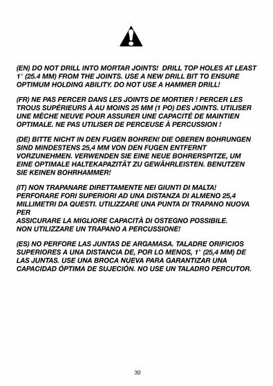
(EN) DO NOT DRILL INTO MORTAR JOINTS! DRILL TOP HOLES AT LEAST 1" (25.4 MM) FROM THE JOINTS. USE A NEW DRILL BIT TO ENSURE OPTIMUM HOLDING ABILITY. DO NOT USE A HAMMER DRILL!
(FR) NE PAS PERCER DANS LES JOINTS DE MORTIER ! PERCER LES TROUS SUPÉRIEURS À AU MOINS 25 MM (1 PO) DES JOINTS. UTILISER UNE MÈCHE NEUVE POUR ASSURER UNE CAPACITÉ DE MAINTIEN OPTIMALE. NE PAS UTILISER DE PERCEUSE À PERCUSSION !
(DE) BITTE NICHT IN DEN FUGEN BOHREN! DIE OBEREN BOHRUNGEN SIND MINDESTENS 25,4 MM VON DEN FUGEN ENTFERNT VORZUNEHMEN. VERWENDEN SIE EINE NEUE BOHRERSPITZE, UM EINE OPTIMALE HALTEKAPAZITÄT ZU GEWÄHRLEISTEN. BENUTZEN SIE KEINEN BOHRHAMMER!
(IT) NON TRAPANARE DIRETTAMENTE NEI GIUNTI DI MALTA! PERFORARE FORI SUPERIORI AD UNA DISTANZA DI ALMENO 25,4 MILLIMETRI DA QUESTI. UTILIZZARE UNA PUNTA DI TRAPANO NUOVA PER ASSICURARE LA MIGLIORE CAPACITÀ DI OSTEGNO POSSIBILE. NON UTILIZZARE UN TRAPANO A PERCUSSIONE!
(ES) NO PERFORE LAS JUNTAS DE ARGAMASA. TALADRE ORIFICIOS SUPERIORES A UNA DISTANCIA DE, POR LO MENOS, 1" (25,4 MM) DE LAS JUNTAS. USE UNA BROCA NUEVA PARA GARANTIZAR UNA CAPACIDAD ÓPTIMA DE SUJECIÓN. NO USE UN TALADRO PERCUTOR.
30 31
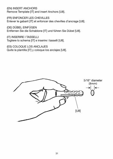
(EN) INSERT ANCHORS Remove Template [IT] and insert Anchors [U8].
(FR) ENFONCER LES CHEVILLES Enlever le gabarit [IT] et enfoncer des chevilles d’ancrage [U8].
(DE) DÜBEL EINFÜGEN Entfernen Sie die Schablone [IT] und führen Sie Dübel [U8].
(IT) INSERIRE I TASSELLI Togliere lo schema [IT] e inserire i tasselli [U8].
(ES) COLOQUE LOS ANCLAJES Quite la plantilla [IT] y coloque los anclajes [U8].
[U8]

32
(EN) INSTALL THE EXTENSION ARM (EA) Install the Extension Arm (EA) using three Lag Bolts [TS] in the “A”, “B” and “C” holes. Do not tighten Lag Bolts completely. After the Wall Mount is on the wall, use a level to make sure the Wall Mount is vertically level.
(FR) POSER LE BRAS ARTICULÉ (EA) Poser le bras articulé (EA) en vissant trois tire-fond [TS] dans les trous « A » « B » et « C ». Ne pas complètement serrer les tire-fond. Une fois que le support mural est sur le mur, utiliser un niveau pour vérifier qu’il est bien vertical.
(DE) INSTALLATION DES VERLÄNGERUNGSARMS (EA) Installieren Sie den Verlängerungsarm (EA) mit drei Ankerbolzen [TS] in die “A” “B” und “C” Löcher. Ziehen Sie die Ankerbolzen nicht vollständig fest. Nach-dem die Wandbefestigung an der Wand angebracht wurde, stellen Sie mit Hilfe eines Nivellierinstruments sicher, dass sie vertikal verläuft.
(IT) INSTALLAZIONE DELLA PROLUNGA (EA) Installare la prolunga (EA) con tre bulloni [TS] nei fori “A” “B” e “C”. Non serrare completamente i bulloni. Dopo aver fissato il supporto alla parete, utilizzare la livella per verificare che il supporto sia parallelo al suolo.
(ES) INSTALACIÓN DEL BRAZO DE EXTENSIÓN (EA) Instale el brazo de extensión (EA) usando tres tirafondos [TS] y arandellas [R] en los orificios “A” “B” y “C”. No ajuste completamente los tirafondos. Una vez que el soporte está sobre la pared, use un nivel para asegurarse que está verticalmente nivelado.

32 33
[EA]
[TS]A
B
C
(EN) DO NOT OVER TIGHTEN LAG BOLTS [TS]!(FR) NE PAS FORCER SUR LES TIRE-FOND [TS] !(DE) ZIEHEN SIE DIE ANKERBOLZEN [TS] NICHT ZU FEST!(IT) NON SERRARE ECCESSIVAMENTE I BULLONI [TS]!(ES) NO AJUSTE DEMASIADO LOS TIRAFONDOS [TS]!
[U8]

34
(EN) PREPARE THE MOUNT FOR INSTALLING THE TV Before you place the television on the wall, first move the Extension Arm [EA] into the straight extended position and make sure the Wall Plate [WP] is level on the wall. Check the Tilt Adjustment. It needs to be tight so it will not tilt during installation. See the Tilt instructions below.
(FN) PREPARACIÓN DEL SOPORTE PARA LA INSTALACIÓN DEL TELEVISORAntes de colocar el televisor en la pared, mueva primero el brazo de exten-sión [EA] a la posición extendida recta y asegúrese de que la placa de pared [WP] esté nivelada en la pared. Revise el ajuste de inclinación. Tiene que estar ajustado para que no se incline durante la instalación. Ver las instrucciones de inclinación a continuación.
(DE) VORBEREITUNG DER MONTAGE FÜR DIE FERNSEHER-INSTALLATIONBevor Sie den Fernseher an der Wand platzieren, versetzen Sie den Erweiter-ungsarm [EA] in die gerade ausgefahrene Position und stellen Sie sicher, dass die Wandplatte [WP] gerade an der Wand sitzt. Überprüfen Sie die Neigestel-lung. Diese muss dicht sein, damit sie während der Installation sich nicht neigt. Zu sehen in den Neigeanweisungen unterhalb.
(IT) PREPARARE LA STAFFA DI MONTAGGIO PER L’INSTALLAZIONE DELLA TVPrima di posizionare la TV sulla parete, spostare il braccio di estensione [EA] in posizione completamente estesa e accertarsi che la piastra da parete [WP] sia a filo con il muro. Controllare la regolazione dell’inclinazione. Deve essere ben serrata per evitare che si inclini durante l’installazione. Vedere le istruzioni di inclinazione indicate di seguito.
(ES) PREPARACIÓN DEL SOPORTE PARA LA INSTALACIÓN DEL TELEVISORAntes de colocar el televisor en la pared, mueva primero el brazo de exten-sión [EA] a la posición extendida recta y asegúrese de que la placa de pared [WP] esté nivelada en la pared. Revise el ajuste de inclinación. Tiene que estar ajustado para que no se incline durante la instalación. Ver las instrucciones de inclinación a continuación.

34 35
[HT]

36
(EN) MOUNT THE TELEVISION With the help of an assistant, lift the television and guide the Monitor Plate [MP] onto the Extension Arm [EA] as shown. Once safely on the mount, continue to hold the TV securely while installing the Security Screws [FS], using the Hex Tool [HT].
(FR) MONTAJE DEL TELEVISORCon la ayuda de un asistente, levante el televisor y guíe la placa del monitor [MP] sobre el brazo de extensión [EA], tal como se muestra. Una vez seguro en el soporte, continúe sosteniendo el televisor de forma segura mientras instala los tornillos de fijación [FS] con el destornillador hexagonal [HT]. Tal vez necesite una persona más en función del tamaño del televisor.
(DE) MONTAGE DES FERNSEHERSMit einem Gehilfen heben Sie den Fernseher an und führen Sie die Bildschirm-platte [MP] wie gezeigt auf die Erweiterungsarm [EA] . Sobald dieser sicher auf der Montage ist, halten Sie den Fernseher weiterhin sicher, während Sie die Sicherheitsschrauben [FS] mit dem Hex-Werkzeug [HT] anziehen. Sie brauchen vielleicht eine weitere Person, abhängig von der Größe des Fernsehers.
(IT) MONTARE LA TVCon l’aiuto di un assistente, sollevare la TV e guidare la piastra del monitor [MP] sulla staffa il braccio di estensione [EA], come mostrato in figura. Una volta saldamente sulla staffa di montaggio, continuare a tenere la TV mentre si installano le viti di sicurezza [FS], utilizzando l’attrezzo esagonale [HT]. Potreb-be essere necessaria un’altra persona a seconda della dimensione della TV.
(ES) MONTAJE DEL TELEVISORCon la ayuda de un asistente, levante el televisor y guíe la placa del monitor [MP] sobre el brazo de extensión [EA] , tal como se muestra. Una vez seguro en el soporte, continúe sosteniendo el televisor de forma segura mientras instala los tornillos de fijación [FS] con el destornillador hexagonal [HT]. Tal vez necesite una persona más en función del tamaño del televisor.

36 37
[EA]
[HT]
[MP]
(EN) Exercise caution when removing the television from the mount to avoid equipment damage or personal injury.
(FR) Lors du décrochage du téléviseur, faire preuve de précaution pour éviter les dommages matériels et corporels.
(DE) Gehen Sie vorsichtig bei der Abnahme des TVs von der Befestigung um, um das Gerät nicht zu beschädigen oder um keine Körperverletzungen zu verursachen.
(IT) Fare attenzione quando viene rimosso il televisore dal supporto, per evitare danni all’apparecchio o alla persona.
(ES) Tenga mucho cuidado al retirar el televisor del soporte para evitar daños en el equipo o lesiones corporales.

38
(EN) USING THE TILT FEATURE Once the television is secured on the Extension Arm (EA), you can adjust the tilt of the television by loosening both Tilt Screws using the Hex Tool (HT). Tilt the television into the desired position, then fully tighten the Tilt Screws again with the Hex Tool. Under no circumstances should these screws be loosened completely and/or removed from the bracket.
(FR) UTILISER LA FONCTION D’INCLINAISON Une fois le téléviseur fixé sur le bras articulé (EA), son inclinaison peut être ajustée en desserrant les deux vis d’inclinaison à l’aide de la clé hexagonale (HT). Incliner le téléviseur jusqu’à la position souhaitée, puis resserrer com-plètement les vis d’inclinaison à l’aide de la clé hexagonale. Ces vis ne doivent en aucun cas être desserrées complètement ou enlevées du support.
(DE) EINSATZ DER KIPPEINRICHTUNG Nachdem der Fernseher am Verlängerungsarm (EA) befestigt wurde, kann nun die Neigung des TVs eingestellt werden. Zu diesem Zweck werden beide Kippschrauben mit dem Sechskantwerkzeug (HT) gelockert. Schwenken Sie dann den Fernseher in die gewünschte Position und ziehen Sie dann die Kippschrauben mit dem Sechskantwerkzeug wieder völlig fest. Unter keinen Umständen dürfen diese Schrauben völlig gelockert und/oder von der Halter-ung abgenommen werden.
(IT) UTILIZZO DELLA FUNZIONE DI INCLINAZIONE Una volta assicurato il televisore allo snodo di prolunga (EA) sarà possibile regolare l’inclinazione dell’apparecchio allentando entrambe le viti con una brugola (HT). Portare il televisore nella posizione desiderata quindi serrare nuovamente le viti. Per nessun motivo si dovranno allentare completamente le viti e/o rimuoverle dal sostegno.
(ES) USO DE LA CARACTERÍSTICA DE INCLINACIÓN Una vez que el televisor está asegurado sobre el brazo de extensión (EA), puede ajustar la inclinación aflojando los dos tornillos de inclinación con la her-ramienta hexagonal (HT). Incline el televisor hasta la posición deseada y luego vuelva a apretar por completo los tornillos de inclinación con la herramienta hexagonal. En ningún caso se deben retirar ni aflojar completamente estos tornillos del soporte.

38 39
[EA]
[HT]
40
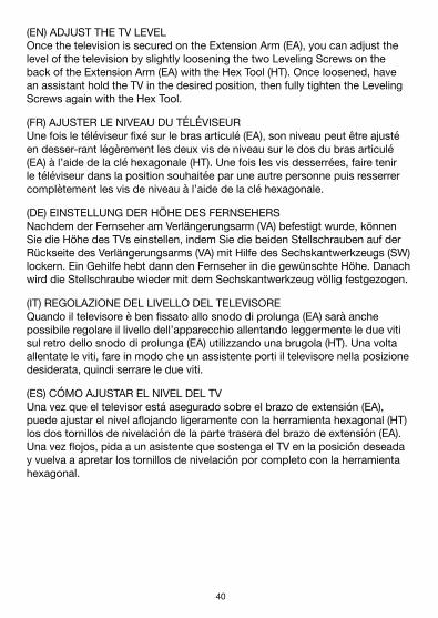
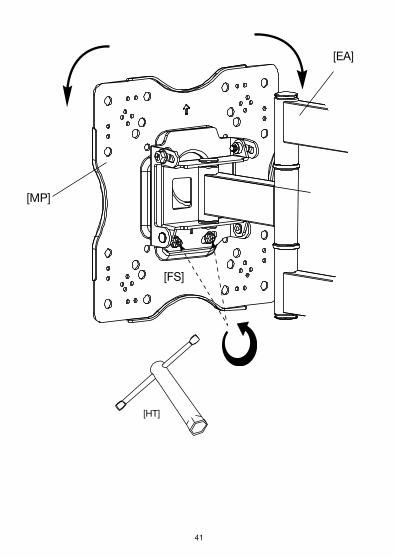
(EN) ADJUST THE TV LEVEL Once the television is secured on the Extension Arm (EA), you can adjust the level of the television by slightly loosening the two Leveling Screws on the back of the Extension Arm (EA) with the Hex Tool (HT). Once loosened, have an assistant hold the TV in the desired position, then fully tighten the Leveling Screws again with the Hex Tool.
(FR) AJUSTER LE NIVEAU DU TÉLÉVISEUR Une fois le téléviseur fixé sur le bras articulé (EA), son niveau peut être ajusté en desser-rant légèrement les deux vis de niveau sur le dos du bras articulé (EA) à l’aide de la clé hexagonale (HT). Une fois les vis desserrées, faire tenir le téléviseur dans la position souhaitée par une autre personne puis resserrer complètement les vis de niveau à l’aide de la clé hexagonale.
(DE) EINSTELLUNG DER HÖHE DES FERNSEHERS Nachdem der Fernseher am Verlängerungsarm (VA) befestigt wurde, können Sie die Höhe des TVs einstellen, indem Sie die beiden Stellschrauben auf der Rückseite des Verlängerungsarms (VA) mit Hilfe des Sechskantwerkzeugs (SW) lockern. Ein Gehilfe hebt dann den Fernseher in die gewünschte Höhe. Danach wird die Stellschraube wieder mit dem Sechskantwerkzeug völlig festgezogen.
(IT) REGOLAZIONE DEL LIVELLO DEL TELEVISORE Quando il televisore è ben fissato allo snodo di prolunga (EA) sarà anche possibile regolare il livello dell’apparecchio allentando leggermente le due viti sul retro dello snodo di prolunga (EA) utilizzando una brugola (HT). Una volta allentate le viti, fare in modo che un assistente porti il televisore nella posizione desiderata, quindi serrare le due viti.
(ES) CÓMO AJUSTAR EL NIVEL DEL TV Una vez que el televisor está asegurado sobre el brazo de extensión (EA), puede ajustar el nivel aflojando ligeramente con la herramienta hexagonal (HT) los dos tornillos de nivelación de la parte trasera del brazo de extensión (EA). Una vez flojos, pida a un asistente que sostenga el TV en la posición deseada y vuelva a apretar los tornillos de nivelación por completo con la herramienta hexagonal.
40 41
[EA]
[MP]
[HT]
[FS]

42
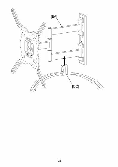
(EN) USING THE CABLE MANAGEMENT FEATURE Feed the Audio Video cables through the Cable Management Cover (CC) as shown. Attach the Cover to the bottom portion of the Extension Arm (EA) by pressing upward until the Cover snaps into place. Remove extra cables if the Cover will not properly attach.
(FR) UTILISER LE SYSTÈME DE PASSE-FIL Enfiler les câbles audio et vidéo à travers le couvercle de passe-fil (CC) comme sur l’illustration. Attacher le couvercle à la branche inférieure du bras articulé (EA) en poussant vers le haut jusqu’à enclencher le couvercle. Retirer les câbles en trop si le couvercle ne s’enclenche pas correctement.
(DE) VERWENDUNG DER KABELMANAGEMENTVORRICHTUNG Führen Sie die Audio- und Videokabel durch die Kabelverwaltungsabdeckung (CC), wie hier abgebildet. Befestigen Sie die Abdeckung an dem Unterteil des Ver-längerungsarms (EA), indem Sie sie solange nach oben drücken, bis sie einrastet. Sollte die Abdeckung nicht ordnungsgemäß einrasten, müssten zusätzliche Kabel wieder herausgenommen werden.
(IT) UTILIZZO DEL SISTEMA DI ORGANIZZAZIONE DEI CAVI Far passare i cavi Audio/Video attraverso il rivestimento del sistema di gestione dei cavi (CC) , come illustrato. Affrancare il rivestimento con i cavi alla parte inferiore della prolunga (EA) facendo forza verso l’alto fino a quando il rivestimento non si blocca in posizione. Eliminare cavi extra nel caso il rivestimento non si blocchi in maniera adeguata.
(ES) USO DE LA CARACTERÍSTICA DE ADMINISTRACIÓN DE CABLES Pase los cables de audio y vídeo a través de la cubierta de administración de cables (CC), tal como se muestra. Fije la cubierta a la parte inferior del brazo de extensión (EA) presionándola hacia arriba hasta que la cubierta encaje en su lugar. Si no se fija correctamente, quite los cables extra.
42 43
[CC]
[EA]

44
English Françias Deutsche Italiano Español
FeedbackLove it? Hate it?Let us know with a customer review.
AmazonBasics is committed to del iver ing customer-dr iven products that l ive up to your high standards. We encourage you to wri te a review shar ing your exper iences with the product.
Please vis i t : https://www.amazon.com/review/review-your-purchases
Warranty InformationTo obtain a copy of the warranty for th is product:
For further service:
Visit amazon.com/gp/help/customer/contact-us
— or —
Contact Customer Service at 1-866-216-1072
Visit amazon.com/AmazonBasics/Warranty
— or —
Contact Customer Service at 1-866-216-1072

44 45
English Françias Deutsche Italiano EspañolInformations sur la garantiePour obtenir une copie de la garant ie de ce produit :
Visitez amazon.com/AmazonBasics/Warranty
— ou —
Contactez le service client au +1-866-216-1072
Pour plus de services:
Visitez amazon.com/gp/help/customer/contact-us
— ou —
Contactez le service client au +1-866-216-1072
Vos commentairesVous adorez? Vous détestez?Laissez-nous votre avis.
AmazonBasics s’engage à fournir des produits qui prennent en compte l’avis de la clientèle et répondent aux attentes élevées qu’elle formule. Nous vous encourageons à nous laisser un commentaire afin de nous faire part de votre expérience du produit.
Rendez-vous sur https://www.amazon.com/review/review-your-purchases
46
English Françias Deutsche Italiano EspañolGarantieHier erhalten Sie eine Kopie der Produktgarant ie:
amazon.com/AmazonBasics/Warranty
— oder —
Wenden Sie sich an den Kundendienst unter +1-866-216-1072
FeedbackGefällt Ihnen das Produkt? Oder überzeugt Sie das Produkt nicht?Sagen Sie es uns mit e iner Kundenrezension.
AmazonBasics möchte Produkte anbieten, die den hohen Erwartungen unserer Kunden gerecht werden. Schreiben Sie eine Rezension und erzählen Sie uns von Ihren Erfahrungen mit dem Produkt.
Besuchen Sie uns unter:
https://www.amazon.com/review/review-your-purchases.
Bei weiteren Servicefragen:
Besuchen Sie amazon.com/gp/help/customer/contact-us
— oder —
Wenden Sie sich an den Kundendienst unter +1-866-216-1072

46 47
English Françias Deutsche Italiano Español
FeedbackTi piace? Non ti piace?Scivi una recensione.
AmazonBasics s i impegna a fornire prodott i che r ispecchiano le esigenze di c l ient i e che soddisfano standard elevat i . T i invi t iamo a scr ivere una recensione per condividere la tua esper ienza con i l prodotto.
Vis i tare: https://www.amazon.it/review/review-your-purchases
Informazioni sulla garanziaPer ottenere una copia del la garanzia per questo prodotto:
Per ul ter iore assistenza:
visitare amazon.it/gp/help/customer/contact-us
— oppure —
contattare il servizio clienti al numero +1-866-216-1072
Visitare amazon.com/AmazonBasics/Warranty
— oppure —
contattare il servizio clienti al numero +1-866-216-1072

48
English Françias Deutsche Italiano Español
Opinión¿Te gusta? ¿Lo odias?Háznoslo saber con una reseña.
AmazonBasics está comprometido a ofrecer productos or ientados al c l iente que se correspondan con tus expectat ivas. Te animamos a escr ibir una reseña compart iendo tus exper iencias con el producto.
Vis i ta: https://www.amazon.com/review/review-your-purchases
Información sobre la garantíaPara obtener una copia de la garant ía de este producto:
Para consultas adicionales:
Visita amazon.com/gp/help/customer/contact-us
— o —ponte en contacto con el servicio de Atención al Cliente a
través del +1-866-216-1072
Visita amazon.com/AmazonBasics/Warranty
— o —
ponte en contacto con el servicio de Atención al Cliente a través del +1-866-216-1072

48 49

50

50 51

52
amazon.com/AmazonBasics
MADE IN CHINA REV. 092616