Auflösung bis 26 Bit
8
Maßbild Aufsteckhohlwelle Allgemeintoleranzen nach DIN ISO 2768-mk ▀ Extrem robust ▀ Busankopplung CAN high-speed ▀ Elektronisch justierbar, Auflösung parametrierbar ▀ Hohe Schock- und Vibrationsfestigkeit ▀ Schutzart bis IP67 PIN- und Aderbelegung für Anschlussadapter A Interne Steckverbindung zum Encoder B Externe Verbindungen zum Bus OUT/US (Buchse) IN/US (Stift) Klemmleiste Gerätestecker Signal Erklärung 1 1 Shield Schirm 2 2 U s (24 V) Betriebsspannung 10 … 32 V 3 3 GND (COM) 0V (Gnd) 4 4 CANH CAN Bus Signal HIGH 5 5 CANL CAN Bus Signal LOW 6 CANH CAN Bus Signal HIGH 7 CANL CAN Bus Signal LOW 8 GND (COM) 0V (Gnd) 9 U s (24 V) Betriebsspannung 10 … 32 V Gerätestecker M12 (Anschlussadapter) Abb. 1 Auflösung bis 26 Bit Absolut-Encoder Multiturn MONTAGEANLEITUNG Absolut-Encoder Multiturn ATM60 CANopen, Aufsteckhohlwelle Zubehör Anschlusstechnik Spannzangen For use in NFPA applications only. Interconnection cables and accessories are available from SICK. Encoder mit einem CAN-Bus-Anschluss- adapter besitzen Verschraubungen (metrisch/PG) zum Anschließen der Bus- und Versorgungsleitungen. Zum Anschluss der Leitungen wird der Anschlussadapter vom Komplettgerät abgeschraubt. Abbildung 1 zeigt die Anschlussbelegung innerhalb des Anschlussadapters. S I CK | 8 0 1 4 8 4 6 / 1EF3 / 2 0 2 1 - 12 - 09 / LF_0 7 Subject to change without notice
Transcript of Auflösung bis 26 Bit
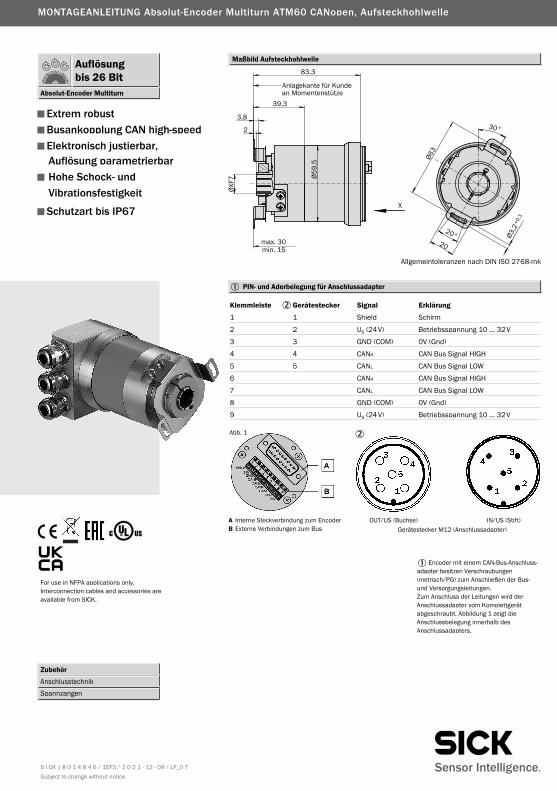
Maßbild Aufsteckhohlwelle
Allgemeintoleranzen nach DIN ISO 2768-mk
▀ Extrem robust
▀ Busankopplung CAN high-speed
▀ Elektronisch justierbar,Auflösung parametrierbar
▀ Hohe Schock- undVibrationsfestigkeit
▀ Schutzart bis IP67
PIN- und Aderbelegung für Anschlussadapter
A Interne Steckverbindung zum EncoderB Externe Verbindungen zum Bus
OUT/US (Buchse) IN/US (Stift)
Klemmleiste Gerätestecker Signal Erklärung
1 1 Shield Schirm
2 2 Us (24V) Betriebsspannung 10 … 32V
3 3 GND (COM) 0V (Gnd)
4 4 CANH CAN Bus Signal HIGH
5 5 CANL CAN Bus Signal LOW
6 CANH CAN Bus Signal HIGH
7 CANL CAN Bus Signal LOW
8 GND (COM) 0V (Gnd)
9 Us (24V) Betriebsspannung 10 … 32V
Gerätestecker M12 (Anschlussadapter)
Abb. 1
Auflösungbis 26 Bit
Absolut-Encoder Multiturn
MONTAGEANLEITUNG Absolut-Encoder Multiturn ATM60 CANopen, Aufsteckhohlwelle
Zubehör Anschlusstechnik Spannzangen
For use in NFPA applications only. Interconnection cables and accessories are available from SICK.
Encoder mit einem CAN-Bus-Anschluss-adapter besitzen Verschraubungen (metrisch/PG) zum Anschließen der Bus- und Versorgungsleitungen. Zum Anschluss der Leitungen wird der Anschlussadapter vom Komplettgerät ab geschraubt. Abbildung 1 zeigt die Anschlussbelegung innerhalb des Anschlussadapters.
S I CK | 8 0 1 4 8 4 6 / 1EF3 / 2 0 2 1 - 12 - 09 / LF_0 7 Subject to change without notice
Aufsteckhohlwelle 6, 8, 10, 12, 15 mm, 1/4”, 3/8”, 1/2”Masse ca. 0,59 kgTrägheitsmoment des Rotors 55 gcm2
Messschritt 0,043°Schrittzahl pro Umdrehung max. 8.192Anzahl der Umdrehungen max. 8.192Fehlergrenzen ± 0,25°Wiederholbarkeit 0,1°Arbeitsdrehzahl 3.000 min-1
Positionsbildungszeit 0,25 msWinkelbeschleunigung max. 5 x 10⁵ rad/s2
Betriebsdrehmoment 1) 0,8 NcmAnlaufdrehmoment 1) 1,2 NcmZulässige Wellenbewegung des Antriebselements radial statisch / dynamisch ± 0,3/± 0,1 mmaxial statisch / dynamisch ± 0,5/± 0,2 mmLagerlebensdauer 3,6 x 10⁹ UmdrehungenArbeitstemperaturbereich –20 … +80 °CLagerungstemperaturbereich –40 … +125 °CZulässige relative Luftfeuchte 98 %EMV 2) Widerstandsfähigkeit gegenüber Schocks 3) 100/6 g/msgegenüber Vibration 4) 20/10 … 2000 g/HzSchutzart nach IEC 60529 IP67 1) ohne Wellendichtring IP43 5)
Betriebsspannungsbereich (Us) 10 … 32 VLeistungsaufnahme max. 2,0 WInitialisierungszeit 6) 1250 msBus Interface CANopenElektrische Schnittstelle 7) ISO-DIS 11898Protokoll Communication Profile DS 301 V4.0
Device Profile DSP 406 V2.0Adresseinstellung (NODE ID) 0 … 63 (DIP-Schalter oder Protokoll)Datenübertragungsrate (Baudrate) {10, 20, 50, 125, 250, 500} kB, 1MB
(DIP-Schalter oder Protokoll)Elektronische Justage (Number SET) über PRESET-Taster oder ProtokollStatus Information 2-farbige LED für CAN Controller StatusBusabschluss 8) über DIP-SchalterElektrischer Anschluss Verschraubung mit PG-9 für Leitung
2) Nach DIN EN 61000-6-2und DIN EN 61000-6-3
3) Nach DIN EN 60068-2-274) Nach DIN EN 60068-2-65) Am Geberflansch nicht abgedichtet6) Ist die Zeit, die nach Anlegen der Versor-
gungsspannung vergeht, bis das Daten-wort korrekt eingelesen werden kann
7) (CAN High Speed) und CAN-Spezifikation 2.0 B, galvanisch getrennt
8) Zuschalten nur bei Endgerät
1) Mit Wellendichtring
1030026Bestell-Nr.
ATM60-CAH13X13Typ
AufsteckhohlwelleBeschreibung
ATM60 CANopen Aufsteckhohlwelle; Us 10 … 32 VoltBestell-Information
Achtung: CANbus Anschlussadapter separat bestellen (siehe Seite 7)
Achtung: Spannzange mit gewünschtem Ø bitte separat bestellen
2029174Bestell-Nr.
SPZ-006-AD-ATyp Wellendurchmesser
6 mmSPZ-1E4-AD-A 2029175 1/4“SPZ-008-AD-A 2029176 8 mmSPZ-3E8-AD-A 2029177 3/8“SPZ-010-AD-A 2029178 10 mmSPZ-012-AD-A 2029179 12 mmSPZ-1E2-AD-A 2029180
Für 15 mm Wellendurchmesser ist keine Spannzange erforderlich
1/2“2048863SPZ-014-AD-A 14 mm
ATM60 CANopen
Aufst.Technische Daten nach DIN 32878 ATM60 CANopen Flanschart
S I CK | 8 0 1 4 8 4 6 / 1EF3 / 2 0 2 1 - 12 - 09 / LF_0 7 Subject to change without notice
▀ Extrem robust
▀ Busankopplung CAN high-speed
▀ Elektronisch justierbar,Auflösung parametrierbar
▀ Hohe Schock- undVibrationsfestigkeit
▀ Schutzart bis IP67
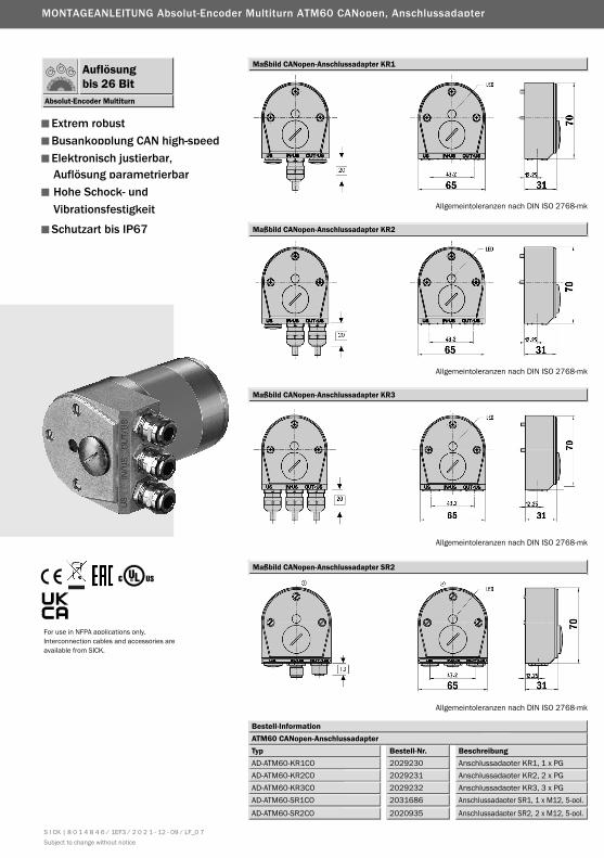
Allgemeintoleranzen nach DIN ISO 2768-mk
Maßbild CANopen-Anschlussadapter KR1
Allgemeintoleranzen nach DIN ISO 2768-mk
Maßbild CANopen-Anschlussadapter KR3
Allgemeintoleranzen nach DIN ISO 2768-mk
Maßbild CANopen-Anschlussadapter SR2
2029230Bestell-Nr.
AD-ATM60-KR1COTyp
Anschlussadapter KR1, 1 x PG2029231AD-ATM60-KR2CO Anschlussadapter KR2, 2 x PG2029232AD-ATM60-KR3CO Anschlussadapter KR3, 3 x PG2031686AD-ATM60-SR1CO Anschlussadapter SR1, 1 x M12, 5-pol.
BeschreibungATM60 CANopen-Anschlussadapter
Maßbild CANopen-Anschlussadapter KR2
Allgemeintoleranzen nach DIN ISO 2768-mk
Bestell-Information
2020935AD-ATM60-SR2CO Anschlussadapter SR2, 2 x M12, 5-pol.
Auflösungbis 26 Bit
Absolut-Encoder Multiturn
MONTAGEANLEITUNG Absolut-Encoder Multiturn ATM60 CANopen, Anschlussadapter
S I CK | 8 0 1 4 8 4 6 / 1EF3 / 2 0 2 1 - 12 - 09 / LF_0 7 Subject to change without notice
For use in NFPA applications only. Interconnection cables and accessories are available from SICK.
ATM60 CANopen
Schaltereinstellungen
Implementierung
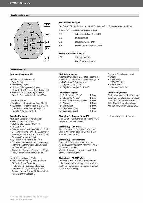
Schaltereinstellungen
Der Zugang für die Bedienung der DIP-Schalter erfolgt über eine Verschraubung
auf der Rückseite des Anschlussadapters.
S 1 Adresseinstellung (Node ID)
S 2 Busabschluss
S 3 Baudrate (Data Rate)
S 4 PRESET-Taster (Number SET)
Statusinformation über LED
LED 2-farbig rot/grün
CAN Controller Status
CANopen-Funktionalität
Predefined Connection Set• Sync-Objekt• Emergency-Objekt• Netzwerk-Management-Objekt
(Error Control Services, Boot-Up Service)• Ein (1) Service-Daten-Objekt (SDO)• Zwei (2) Prozess-Daten-Objekte (PDO)
I/O-Betriebsarten• Synchron. -- Abhängig von Sync-Objekt• Asynchron. -- Triggerung erfolgt zyklisch
oder durch Positionsänderung (COS)• Remote-Anforderung (RTR)
Encoder-Parameternach dem Geräteprofil für Encoder:• Zählrichtung (CW, CCW)• Skalierungsfunktion (ON, OFF)• PRESET-Wert• Schritte pro Umdrehung (SpU) - 1…8.192• Gesamtauflösung (GA) -- 1…67.108.864
Schritte, mit GA = 2n x SpU -- (n=0…13)• Grenzen für Arbeitsbereich• Zyklus-Timer für Asynchron PDOs• 8 programmierbare Nocken mit oberer/
unterer Schaltschwelle und Hysteresis für die Schaltpunkte
• Allgemeine Diagnose-Parameter (Offset- Wert, Alarme, Warnungen, Version)
Herstellerspezifisches Profil: • Adresszuordnung: -- Quelle und Werte
für Node-ID und Baudrate• Hysteresis für Positionsänderungen
in Betriebsart Async PDOs mit COS• Grenzwerte und Format für Geschwindig-
keit und Beschleunigung.
PDO Data MappingZuordnung von bis zu vier Datenobjekten zu jedem der beiden PDOs. Die Datenlänge für ein PDO ist auf 8 Byte begrenzt.(1) Objekt 1/PosW 1) I-1(n) Objekt 2 ... Objekt 4 I-1 to I-7
Input-Daten-ObjekteI-1 Positionswert [PosW] 4 ByteI-2 Status der Nocken 1 ByteI-3 Status des Arbeitsbereichs 1 ByteI-4 Alarme 1 ByteI-5 Warnungen 1 ByteI-6 Geschwindigkeit 4 ByteI-7 Beschleunigung 4 Byte
Einstellung: - Adresse (Node ID)0 bis 63 über DIP-Schalter, oder per Softwa-re (gespeichert in EEPROM)
Einstellung: - Baudrate10k, 20k, 50k, 125k, 250k, 500k, 1 MB über DIP-Schalter, oder per Software (ge-speichert in EEPROM)
Einstellung: - BusabschlussEin 2-pol. DIP-Schalter ermöglicht das Zu- und Abschalten eines internen Busab-schlusses (ON/OFF).Wird der Bus extern terminiert, bleibt DIP-Schalter in Stellung OFF.
Einstellung: - PRESET-WertDie PRESET-Funktion dient zur Inbetrieb-nahme und der Zuordnung eines bestimm-ten Positionswertes zur aktuellen physikali-schen Winkelstellung.
Folgende Einstellungen sind möglich:• per Hardware
(PRESET-Taster)• per Software
(CANopen-Protokoll)
GerätekonfigurationZur Inbetriebnahme des Encoders durch ein Konfigurationswerkzeug dient die EDS-Datei (Electronic Data Sheet). Sie enthält alle not-wendigen Merkmale des Gerätes.
1) Einstellung nicht änderbar
S I CK | 8 0 1 4 8 4 6 / 1EF3 / 2 0 2 1 - 12 - 09 / LF_0 7 Subject to change without notice
S I CK | 8 0 1 4 8 4 6 / 1EF3 / 2 0 2 1 - 12 - 09 / LF_0 7 Subject to change without notice
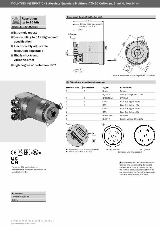
Dimensional drawing blind hollow shaft
General tolerances according DIN ISO 2768-mk
▀ Extremely robust
▀ Bus coupling to CAN high-speedspecification
▀ Electronically adjustable,resolution adjustable
▀ Highly shock- andvibration-proof
▀ High degree of protection IP67
PIN and wire allocation for bus adapter
A Internal plug connection to the encoderB External connection to the bus
OUT/Us (female) IN/Us (male)
Terminal strip Connector Signal Explanation
1 1 Shield Screen
2 2 Us (24V) Supply voltage 10 … 32V
3 3 GND (COM) 0V (Gnd)
4 4 CANH CAN Bus Signal HIGH
5 5 CANL CAN Bus Signal LOW
6 CANH CAN Bus Signal HIGH
7 CANL CAN Bus Signal LOW
8 GND (COM) 0V (Gnd)
9 Us (24V) Supply voltage 10 … 32V
Connector M12 (Bus adapter)
Figure 1
Resolutionup to 26 bits
Absolute Encoders Multiturn
MOUNTING INSTRUCTIONS Absolute Encoders Multiturn ATM60 CANopen, Blind Hollow Shaft
Accessories Connection systems Collets
Encoders with a CANbus adapter have a terminal strip for connecting the bus and supply lines. In order to connect the lines, the Profibus adapter is unscrewed from the complete device. The figure 1 shows the pin allocation within the bus connection.
For use in NFPA applications only. Interconnection cables and accessories are available from SICK.
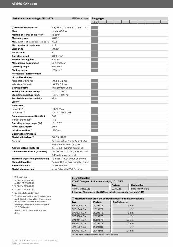
Hollow shaft diameter 6, 8, 10, 12, 15 mm, 1/4”, 3/8”, 1/2”Mass Approx. 0.59 kgMoment of inertia of the rotor 55 gcm2
Measuring step 0.043°Max. number of steps per revolution 8,192Max. number of revolutions 8,192Error limits ± 0.25°Repeatability 0.1°Operating speed 3,000 min-1
Position forming time 0.25 msMax. angular acceleration 5 x 10⁵ rad/s2
Operating torque 0.8 Ncm 1)
Start up torque 1.2 Ncm 1) Permissible shaft movement of the drive element radial static/dynamic ± 0.3/± 0.1 mmaxial static/dynamic ± 0.5/± 0.2 mmBearing lifetime 3.6 x 10⁹ revolutionsWorking temperature range – 20 … + 80 °CStorage temperature range – 40 … + 125 °CPermissible relative humidity 98 %EMC 2) Resistanceto shocks 3) 100/6 g/msto vibration 4) 20/10 … 2000 g/HzProtection class acc. IEC 60529 1) IP67without shaft seal 5) IP43Operating voltage range (Us) 10 … 32 VPower consumption 2.0 WInitialisation time 6) 1250 msBus Interface CANopenElectrical interface 7) ISO-DIS 11898Protocol Communication Profile DS 301 V4.0
Device Profile DSP 406 V2.0Address setting (NODE ID) 0 … 63 (DIP switches or protocol)Data transmission rate (Baudrate) {10, 20, 50, 125, 250, 500} kB, 1MB
(DIP switches or protocol)Electronic adjustment (number SET) Via PRESET push button or protocolStatus Information 2-colour LED for CAN Controller statusBus termination 8) Via DIP switches Electrical connection Screw fixing with PG-9 for cable
2) To DIN EN 61000-6-2and DIN EN 61000-6-3
3) To DIN EN 60068-2-274) To DIN EN 60068-2-65) Not sealed at encoder flange6) From the moment the supply voltage is ap-
plied, this is the time which elapses before the data word can be correctly read in.
7) (CAN High Speed) and CAN Specification2.0 B, DC isolated
1030026Part no.
ATM60-CAH13X13Type
Blind hollow shaftExplanation
ATM60 CANopen blind hollow shaft; Us 10 … 32 V
8) Should only be connected in the final device
Attention: Please order the CANbus adapter separately (see page 148)
1) With shaft seal Order information
Attention: Please order the collet with required diameter separately
2029174Part no.
SPZ-006-AD-AType Shaft diameter
6 mmSPZ-1E4-AD-A 2029175 1/4“SPZ-008-AD-A 2029176 8 mmSPZ-3E8-AD-A 2029177 3/8“SPZ-010-AD-A 2029178 10 mmSPZ-012-AD-A 2029179 12 mmSPZ-1E2-AD-A 2029180
For 15 mm shaft diameter, collet is not needed
1/2“
SPZ-014-AD-A 2048863 14 mm
ATM60 CANopen
blindTechnical data according to DIN 32878 ATM60 CANopen Flange type
S I CK | 8 0 1 4 8 4 6 / 1EF3 / 2 0 2 1 - 12 - 09 / LF_0 7 Subject to change without notice
General tolerances according DIN ISO 2768-mk
▀ Extremely robust
▀ Bus coupling to CAN high-speedspecification
▀ Electronically adjustable,resolution adjustable
▀ Highly shock- andvibration-proof
▀ High degree of protection IP67
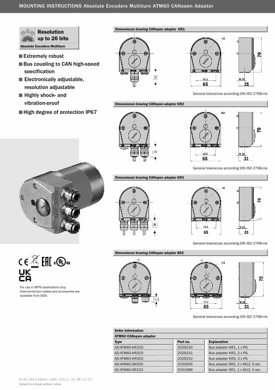
Dimensional drawing CANopen adapter KR1
General tolerances according DIN ISO 2768-mk
Dimensional drawing CANopen adapter KR3
General tolerances according DIN ISO 2768-mk
Dimensional drawing CANopen adapter SR2
2029230Part no.
AD-ATM60-KR1COType
Bus adapter KR1, 1 x PG2029231AD-ATM60-KR2CO Bus adapter KR2, 2 x PG2029232AD-ATM60-KR3CO Bus adapter KR3, 3 x PG2020935AD-ATM60-SR2CO Bus adapter SR2, 2 x M12, 5 pin.
ExplanationATM60 CANopen adapter
Dimensional drawing CANopen adapter KR2
General tolerances according DIN ISO 2768-mk
Order information
2031686AD-ATM60-SR1CO Bus adapter SR1, 1 x M12, 5 pin.
Resolutionup to 26 bits
Absolute Encoders Multiturn
MOUNTING INSTRUCTIONS Absolute Encoders Multiturn ATM60 CANopen Adapter
S I CK | 8 0 1 4 8 4 6 / 1EF3 / 2 0 2 1 - 12 - 09 / LF_0 7 Subject to change without notice
For use in NFPA applications only. Interconnection cables and accessories are available from SICK.
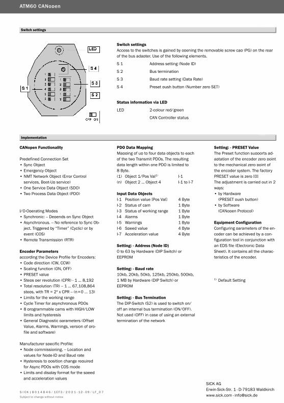
Switch settings
Implementation
Switch settingsAccess to the switches is gained by opening the removable screw cap (PG) on the rear of the bus adapter. Use of the following elements.
S 1 Address setting (Node ID)
S 2 Bus termination
S 3 Baud rate setting (Data Rate)
S 4 Preset push button (Number zero SET)
Status information via LED
LED 2-colour red/green
CAN Controller status
CANopen Functionality
Predefined Connection Set• Sync Object• Emergency Object• NMT Network Object (Error Control
services, Boot-Up service)• One Service Data Object (SDO)• Two Process Data Object (PDO)
I/O-Operating Modes• Synchronic: -- Depends on Sync Object• Asynchronous. -- No reference to Sync Ob-
ject. Triggered by “Timer” (Cyclic) or by event (COS)
• Remote Transmission (RTR)
Encoder Parametersaccording the Device Profile for Encoders: • Code direction (CW, CCW)• Scaling function (ON, OFF)• PRESET value• Steps per revolution (CPR) - 1 … 8,192• Total resolution (TR) -- 1 … 67,108,864
steps, with TR = 2n x CPR -- (n=0 … 13)• Limits for the working range• Cycle Timer for asynchronous PDOs• 8 programmable cams with HIGH/LOW
limits and hysteresis• General Diagnostic parameters (Offset
Value, Alarms, Warnings, version of pro-file and software)
Manufacturer specific Profile: • Node commissioning. -- Location and
values for Node-ID and Baud rate• Hysteresis to position change required
for Async PDOs with COS mode• Limits and display format for the speed
and acceleration values
PDO Data MappingMapping of up to four data objects to each of the two Transmit PDOs. The resulting data length within one PDO is limited to8 Byte.(1) Object 1/Pos Val1) I-1(n) Object 2 … Object 4 I-1 to I-7
Input Data ObjectsI-1 Position value [Pos Val] 4 ByteI-2 Status of cam 1 ByteI-3 Status of working range 1 ByteI-4 Alarms 1 ByteI-5 Warnings 1 ByteI-6 Speed value 4 ByteI-7 Acceleration value 4 Byte
Setting: - Address (Node ID)0 to 63 by Hardware (DIP Switch) or EEPROM
Setting: - Baud rate10kb, 20kb, 50kb, 125kb, 250kb, 500kb, 1 MB by Hardware (DIP Switch) or EEPROM
Setting: - Bus TerminationThe DIP-Switch (S2) is used to switch on/ off an internal bus termination (ON/OFF).Not used (OFF) in case of using an external termination of the network
Setting: - PRESET ValueThe Preset function supports ad-aptation of the encoder zero point to the mechanical zero point of the encoder system. The factory PRESET value is zero [0]The adjustment is carried out in 2 ways: • by Hardware
(PRESET push button)• by Software
(CANopen Protocol)
Equipment Configuration Configuring parameters of the en-coder can be achieved by a con-figuration tool in conjunction with an EDS file (Electronic Data Sheet). It contains all the charac-teristics of the encoder.
1) Default Setting
ATM60 CANopen
SICK AGErwin-Sick-Str. 1 · D-79183 Waldkirchwww.sick.com · [email protected]
S I C K | 8 0 1 4 8 4 6 / 1EF3 / 2 0 2 1 - 12 - 09 / L F _ 0 7 Subject to change without notice


![TFT – // · ein Modul [1] von Adafruit [2], das eine farbige Anzeige mit einer Auflösung von 18-Bit (262.144) ermöglicht und eine Größe von 1,8“ aufweist. Die Ansteuerung](https://static.fdokument.com/doc/165x107/60560a09612834006d509e75/tft-a-ein-modul-1-von-adafruit-2-das-eine-farbige-anzeige-mit-einer-auflsung.jpg)


![ADC-20 und ADC-24 › download › datasheets › adc20...Datenlogger ADC-20 und ADC-24 ADC-20 ADC-24 Auflösung 20 Bit 24 Bit Anzahl Kanäle[1] 4 differenzial / 8 einpolig 8 differenzial](https://static.fdokument.com/doc/165x107/5f23cbdc98bf2e58da663aad/adc-20-und-adc-24-a-download-a-datasheets-a-adc20-datenlogger-adc-20-und.jpg)