BH928 EN 19 - Frank's Hospital Workshop€¦ · STEREODYNATOR 928 gbo Medizintechnik AG 2004...
66
gbo Medizintechnik AG 2004 Version 1.9 Interference Current Stimulation Devices STEREODYNATOR 928 User Manual
Transcript of BH928 EN 19 - Frank's Hospital Workshop€¦ · STEREODYNATOR 928 gbo Medizintechnik AG 2004...

gbo Medizintechnik AG 2004 Version 1.9
Interference Current Stimulation Devices
STEREODYNATOR 928
User Manual

STEREODYNATOR 928
gbo Medizintechnik AG 2004 Version 19
2
Das vorliegende Handbuch wurde von der gbo Medizintechnik AG erstellt und auf seine Richtigkeitüberprüft. Es erhebt jedoch keinen Anspruch auf Vollständigkeit. Alle Angaben und Daten können ohnevorherige Ankündigung geändert werden.
Ohne ausdrückliche schriftliche Genehmigung der gbo Medizintechnik AG darf kein Teil dieses Handbuchfür irgendwelche Zwecke vervielfältigt oder übertragen werden, unabhängig davon, auf welche Art undWeise oder mit welchen Mitteln, elektronisch oder mechanisch, dies geschieht.
The gbo Medizintechnik AG has taken care in preparation of this manual, but makes no expressed orimplied warranty of any kind and assume no responsibility for errors or omissions.
All rights reserved. No part of this manual may be reproduced, in any form or by any means (electronic,mechanical, or otherwise) without the prior written permission of the gbo Medizintechnik AG.
© gbo Medizintechnik AG 2004
gbo Medizintechnik AGKleiststraße 6D-64668 Rimbach
Telephone:+49 / 6 25 3 / 808-0Telefax: +49 / 6 25 3 / 808-300E-Mail: [email protected]: http://www.gbo-med.de
STEREODYNATOR 928
gbo Medizintechnik AG 2004 Version 1.9
3
Comments According to the Medical Device Directive
The STEREODYNATOR 928 is a mains operated current stimulation device of protection class I.
The device is in accordance with the EC Medical Device Directive (93/42/EEC) and therefore carries theCE-sign with the number of the ”notified body for medical devices”. The according graphical symbol isplaced on the type plate.
According to the Medical Device Directive, STEREODYNATOR 928 is a device of class IIb.
The manufacturer is only responsible for the security, operational reliability and functionality of the deviceif:
• the device is used in accordance with the user manual;• the electrical installation of the location where the device will be used corresponds to the
respective current requirements of electrical safety;• the device is not used in hazardous environments and humid locations;• the mountings, add ons, internal adjustments, modifications or repairs are realized only by
personnel authorized for that by the manufacturer;• the operator regulation of this EC-directive is observed within the scope of the Medical Device
Directive.
You may obtain technical support by the manufacturer or the dealers or service authorized by themanufacturer. The manufacturer provides a life time of at least 10 years for this product.
STEREODYNATOR 928 is a electronic device. Disposing has to be done according to regulationsfor electronic devices. Consumables have to be disposed as garbage.
On request, the manufacturer will provide you with further technical descriptions for all serviceable parts ofthe device, such as circuit diagrams, spare part lists, and adjustment instructions as far as these are of use forthe qualified technical staff of the user.
Comments on electromagnetic compatibility (EMC)Medical, electrical devices are subject to special precautions concerning the EMC. They must be installedand operated according to the EMC-advice given in the accompanying documents. In particular medical,electrical devices may be influenced by portable and mobile RF-communication devices.
The manufacturer guarantees the conformity of the unit with the EMC-requirements only when usingaccessories which are listed in the EC declaration of conformity. The usage of other accessories my cause anincreased emission of electromagnetic disturbances or may lead to a reduced electromagnetic immunity.
The unit must not be arranged physically close to other devices or stacked with them. If such an order isnecessary nevertheless, the unit must be observed in order to check it for the intentional operation.
You find more EMC-comments in the chapter “Warnings and Safety Precautions” of this manual as well asin the Technical Information on the next two pages.

STEREODYNATOR 928
gbo Medizintechnik AG 2004 Version 19
4
In accordance with the EMC-regulations for medical products we are obliged by law toprovide the following information.
Guidance and manufacturer’s declaration — electromagnetic emissions
The equipment is intended for use in the electromagnetic environment specified below. The customer orthe user of the equipment should assure that it is used in such an environment.
Emissions test Compliance Electromagnetic environment – guidanceRF emissions,CISPR 11
Group 1 The equipment uses RF energy only for its internal function.Therefore, its RF emissions are very low and are not likely to causeany interference in nearby electronic equipment.
RF emissions,CISPR 11
Class B
Harmonic emissions,IEC 61000-3-2 (*)
Class A
Voltage fluctuation/flickeremissions, IEC 61000-3-3 (*)
Complies
The equipment is suitable for use in all establishments, includingdomestic establishments and those directly connected to the publiclow-voltage power supply network that supplies buildings used fordomestic purposes.
(*) Note: For devices with a power consumption between 75 W and 1000 W only.
Guidance and manufacturer’s declaration — electromagnetic immunity
The equipment is intended for use in the electromagnetic environment specified below. The customer orthe user of the equipment should assure that it is used in such an environment.
Immunity test IEC 60601- test level Compliance level Electromagnetic environment –guidance
Electrostatic discharge (ESD),IEC61000-4-2
±6 kV contact
±8 kV air
±6 kV contact
±8 kV air
Floors should be wood, concrete orceramic tile. If floors are covered withsynthetic material, the relative humidityshould be at least 30 %.
Electrical fast transient/burst,IEC 61000-4-4
±2 kV for power supplylines
±1 kV for input/outputlines
±2 kV for power supplylines
±1 kV for input/outputlines
Mains power quality should be that of atypical commercial or hospitalenvironment.
Surge,IEC 61000-4-5
±1 kV differential mode
±2 kV common mode
±1 kV differential mode
±2 kV common mode
Mains power quality should be that of atypical commercial or hospitalenvironment.
Voltage dips, shortinterruptions and voltagevariations on power supplyinput lines,IEC 61000-4-11
<5% Uτfor ½ cycle(>95% dip)
40% Uτfor 5 cycles60% dip)
70% Uτfor 25 cycles30% dip)
<95% Uτfor 5 s(>5% dip)
<5% Uτfor ½ cycle(>95% dip)
40% Uτfor 5 cycles60% dip)
70% Uτfor 25 cycles30% dip)
<95% Uτfor 5 s(>5% dip)
Mains power quality should be that of atypical commercial or hospitalenvironment.
If the user of the equipment requirescontinued operation during power mainsinterruptions, it is recommended that theequipment be powered from anuninterruptible power supply or abattery.
Power frequency (50/60 Hz)magnetic field,IEC 61000-4-8
3 A/m 3 A/m Power frequency magnetic fields shouldbe at levels characteristic of a typicallocation in a typical commercial orhospital environment.
Note: Uτ is the a.c. mains voltage prior to application of the test level.

STEREODYNATOR 928
gbo Medizintechnik AG 2004 Version 1.9
5
Guidance and manufacturer’s declaration — electromagnetic immunity
The equipment is intended for use in the electromagnetic environment specified below. The customer orthe user of the equipment should assure that it is used in such an environment.
Immunity test IEC 60601- test level Compliance level Electromagnetic environment –guidance
Portable and mobile RF communicationsequipment should be used no closer to anypart of the equipment, including cables,than the recommended separation distancecalculated from the equation applicable tothe frequency of the transmitter.
Recommended separation distance:Conducted RF,IEC 61000-4-6
3 Vrms150 kHz to 80 MHz
3 Veff d=1,2√P
Radiated RF,IEC 61000-4-3
3 V/m80 MHz to 2,5 GHz
3V/m d=1,2√Pfor 80 MHz to 800 MHzd=2,3√Pfor 800 MHz to 2,5 GHzWhere P is the maximum output powerrating of the transmitter in watts accordingto the transmitter manufacturer and d is therecommended separation distance inmeters (m).
Interference may occur in the vicinity ofequipment marked with the followingsymbol:
Recommended separation distances to portable and mobile RF communication equipment
The equipment is intended to be operated in an electromagnetic environment, where radiated RFinterference is controlled. The user can help in avoiding interferences by means of meeting minimumseparation distances between portable and mobile RF communication equipment (transmitters) accordingto the maximum output power of the communication equipment.
Separation distance according to the tranmission frequency (m)Rated power of thetransmitter (W) 150 kHz to 80 MHz
d=1,2√√√√P80 MHz to 800 MHz
d=1,2√√√√P800 MHz to 2,5 GHz
d=2,3√√√√P0,01 0,12 0,12 0,23
0,1 0,38 0,38 0,73
1 1,2 1,2 2,3
10 3,8 3,8 7,3
100 12 12 23
STEREODYNATOR 928
gbo Medizintechnik AG 2004 Version 19
6
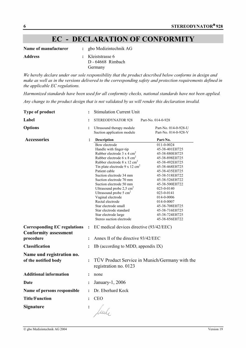
EC - DECLARATION OF CONFORMITYName of manufacturer : gbo Medizintechnik AG
Address : Kleiststrasse 6D - 64668 RimbachGermany
We hereby declare under our sole responsibility that the product described below conforms in design andmake as well as in the versions delivered to the corresponding safety and protection requirements defined inthe applicable EC regulations.
Harmonized standards have been used for all conformity checks, national standards have not been applied.
Any change to the product design that is not validated by us will render this declaration invalid.
Type of product : Stimulation Current Unit
Label : STEREODYNATOR 928 Part-No. 014-0-928
Options : Ultrasound therapy module Part-No. 014-0-928-USuction application module Part-No. 014-0-928-V
Accessories : Description Part-No.Bow electrode 011-0-0024Handle with finger-tip 45-38-401EH725Rubber electrode 3 x 4 cm2 45-38-880EH725Rubber electrode 6 x 8 cm2 45-38-898EH725Rubber electrode 8 x 12 cm2 45-38-492EH725Tin plate electrode 9 x 12 cm2 45-38-468EH725Patient cable 45-38-435EH725Suction electrode 34 mm 45-38-518EH722Suction electrode 70 mm 45-38-526EH722Suction electrode 50 mm 45-38-500EH722Ultrasound probe 2,5 cm2 023-0-0140Ultrasound probe 5 cm2 023-0-0141Vaginal electrode 014-0-0006Rectal electrode 014-0-0007Star electrode small 45-38-708EH725Star electrode standard 45-38-716EH725Star electrode large 45-38-724EH725Stereo suction electrode 45-38-856EH722
Corresponding EC regulations : EC medical devices directive (93/42/EEC)Conformity assessmentprocedure : Annex II of the directive 93/42/EEC
Classification : IIb (according to MDD, appendix IX)
Name und registration no.of the notified body : TÜV Product Service in Munich/Germany with the
registration no. 0123Additional information : none
Date : January-1, 2006Name of persons responsible : Dr. Eberhard Keck
Title/Function : CEO
Signature :

STEREODYNATOR 928
gbo Medizintechnik AG 2004 Version 1.9
7
NotationsTimes New Roman in type size 11 - descriptions and explanations
Arial in type size 10 - functions and keys of the current stimulation device
Lucida in type size 11 - text appears on the display of the current stimulation device
[[[[Descriptions]]]] - text appears on the display next to the soft key
Pictographs
AttentionWarnings which have to be observed by all means !
Attention !Observe the instructions for use !
!! Note Information that will facilitate your work.

STEREODYNATOR 928
gbo Medizintechnik AG 2004 Version 19
8
Table of ContentsOVERVIEW 11
1 INTRODUCTION 121.1 Intended Use 12
1.2 Operating Concept 14
1.3 Short Instructions 15
1.4 Modes of Action of the Therapeutic Current Types 17
2 START OF OPERATION 182.1 Transport and Assembly 18
2.2 Connection and Switch-On 18
2.3 Settings 192.3.1 Device Settings 192.3.2 Basic Settings of the Current Types 20
3 DESCRIPTION OF FUNCTION 213.1 Operating Notes 21
3.1.1 Optical and Acoustical User Support 213.1.2 Intensity Regulator 223.1.3 Current and Polarity 223.1.4 Surge Parameters 243.1.5 Galvanic Base 243.1.6 Frequency Lock 243.1.7 Pulse Parameter 253.1.8 Therapy Time 253.1.9 Stimulation shifting 263.1.10 Menu 273.1.11 Menu Programs 28
3.2 Integrated Suction Application Aid 29
3.3 Ultrasound Therapy Module 30
4 THERAPY 324.1 Therapy with interference currents 32
4.1.1 Sedat 324.1.2 Myomot 334.1.3 Vegetative Stimulation I 334.1.4 Vegetative Stimulation II 334.1.5 Vegetative Stimulation III 334.1.6 Universal 334.1.7 Sedation Modulation 334.1.8 Automated programs 34
4.2 Menu Application With Electrotherapy 35
4.3 Menu ‘Applications with ultrasound’ 36
4.4 ”One - Touch” - Operation 364.4.1 Diadynamic Currents 364.4.2 Strong Muscle Stimulation (SMS) According to Eichhorn 374.4.3 Middle Frequency Currents 374.4.4 Ultrastimulation Current 38

STEREODYNATOR 928
gbo Medizintechnik AG 2004 Version 1.9
9
4.4.5 High-Voltage Currents 384.4.6 Galvanic Current and Iontophoresis 394.4.7 Faradic Current 404.4.8 Transcutaneous Electrical Nerve Stimulation 404.4.9 Transcutaneous Electrical Nerve Stimulation With Impulse Groups 414.4.10 Micro-Stimulus Current 424.4.11 Universal Therapy 42
4.5 Special types of current Menu 424.5.1 Impulse Galvanization 434.5.2 Frequency Modulation 434.5.3 Diadynamic Currents MF Monophasé Fixe and LP Longues Périodes 434.5.4 Rectangular Current for Incontinence 43
4.6 GYM 444.6.1 GYM current 444.6.2 GYM Training 454.6.3 Burning mode 45
5 GALVANOPALPATION 46
6 ELECTROKINETIC THERAPY 476.1 Detection of Trigger Points With the Electrode Handpiece 47
6.2 Stimulation Massage 47
7 ELECTRODES 487.1 Electrode Positioning 48
7.1.1 Monophase Electrode Techniques 497.1.2 Biphase Electrode Techniques 49
7.2 Single-Pole Electrodes 49
7.3 Three-pole electrodes 51
7.4 Suction Electrodes 51
7.4 Suction Electrodes 52
7.5 Electrode Handpiece 52
8 TROUBLESHOOTING 53
9 MAINTENANCE 549.1 Safety Controls 54
9.2 Cleaning, Disinfection and Care 549.2.1 Current Stimulation Device 549.2.2 Electrode Fleece, Electrode Pockets or Felts 54
10 WARNINGS AND SAFETY PRECAUTIONS 55
11 EXPLANATION OF THE SIGNS USED 57
12 TECHNICAL DATA 58
13 ACCESSORIES 61
INDEX 57

STEREODYNATOR 928
gbo Medizintechnik AG 2004 Version 19
10
APPENDIX: STORING OF THERAPEUTIC CURRENT TYPES 59

STEREODYNATOR 928
gbo Medizintechnik AG 2004 Version 1.9
11
OverviewChapter 1 describes the basic characteristics of the current stimulation device.
Chapter 2 explains the start of operation of the current stimulation device. It describes its settingpossibilities.
Chapter 3 describes all functions of the device and their operation.
Chapter 4 explains the realization of therapies.
Chapter 5 explains the realization of galvanopalpation.
Chapter 6 explains the realization of electrokinesis.
Chapter 7 refers to the arrangement and the use of the electrodes.
Chapter 8 explains the error messages and gives some hints in the case of faults.
Chapter 9 refers to safety controls in accordance with the MDD and to routine maintenance.
Chapter 10 shows the possible threats when using the current stimulation device. Furthermore, itindicates how to avoid possible threats.
Chapter 11 explains the signs used.
Chapter 12 speifies all relevant technical data of the current stimulation device.
Chapter 13 shows the scope of supply of the device and informs about further accessories indicatingtheir order number.

STEREODYNATOR 928
gbo Medizintechnik AG 2004 Version 19
12
1 Introduction
1.1 Intended Use
The devices with interference current are microprocessor controlled electrical stimulus devices for ElectroTherapy. Their wide range of usage predestinates these medical devices for use in physiotherapeuticdepartments of clinics as well as in modern well-equipped private practices.
The devices with interference current represent a continued development, based on the 8th series equipment.All accessories of the 8th series can also be used with the 9th generation in the same manner. A suctionapplication aid for vacuum therapy as well as a module for ultrasound therapy with continuous and impulseultrasound waves are optionally available. The control elements for suction application aid and ultrasoundhave already been integrated on the keyboard.
A stereodynamic interference current is generated through the superposition of three middle-frequencycurrents flowing in different directions. The stimulating lower frequencies are already generated throughinterference of two phase shifted circuits in the area being stipulated. The additional third circuit generates,as opposed to classical interference methods, on one side a slow change in intensity and on the other side arhythmic shifting of the interference field. These dynamics of the stimulation location and the intensitydynamics decrease the habituation effect and therefore improve the therapeutic effect. TheSTEREODYNATOR 928 uses the three-dimensional interference method. The special characteristics areas follows:
• Local stimulation effect.• Multi-site stimulation effect.• Intensity dynamics.• Dynamic behavior of stimulation site coupled with endogenous/exogenous stimulation shifting.
Automated programs improve the handling: The STEREODYNATOR 928 is equipped with severalprograms which automatically adjust the treatment frequency and the treatment time. Treatment frequencies,particularly for sedation, myokinetics and vegetative stimulation, are available.
The stimulating effect can alternatively be administrated endogenously or exogenously. During endogenousapplication, the interference is generated through superposition of the electrical circuits in the body. Thisallows an intense effect. During exogenous application, the interference is created in the medical device.The stimulating effect takes place directly underneath the electrodes on the body surface.
In addition to the three-circuit interference current, STEREODYNATOR 928 offers a complete selection ofsingle circuit currents for all known therapeutic procedures.

STEREODYNATOR 928
gbo Medizintechnik AG 2004 Version 1.9
13
The STEREODYNATOR 928 is particularly suitable for:• Pain therapy with three-dimensional interference current.• Muscle toning and muscle detoning.• Galvanization and iontophoresis.• Pelvic floor stimulation.• Treatment of urinary and fecal incontinence.• Neurodiagnostic examination with galvano-palpations.• Treatment of paralyses with complete or partial muscular degeneration.• Treatment of atrophies due to inactivity or weakened muscles after longer periods of inactivity.• Electrical stimulation therapy without electrolytic side effects and only slight muscle fatigue.• Treatment of pain, muscle spasms, functional diseases of the locomotor system, such as sports injuries,
peripheral circulatory disturbances, influencing of the vegetative system with diadynamic currents,ultrastimulation current, microstimulation current, TENS- and TENS Burst currents, high-voltagecurrents and middle-frequency currents.
STEREODYNATOR 928
gbo Medizintechnik AG 2004 Version 19
14
1.2 Operating Concept
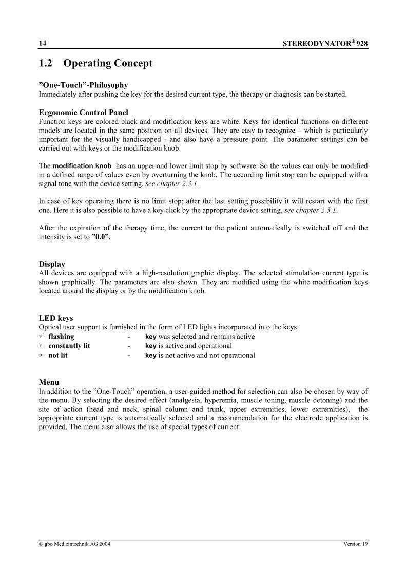
”One-Touch”-PhilosophyImmediately after pushing the key for the desired current type, the therapy or diagnosis can be started.
Ergonomic Control PanelFunction keys are colored black and modification keys are white. Keys for identical functions on differentmodels are located in the same position on all devices. They are easy to recognize – which is particularlyimportant for the visually handicapped - and also have a pressure point. The parameter settings can becarried out with keys or the modification knob.
The modification knob has an upper and lower limit stop by software. So the values can only be modifiedin a defined range of values even by overturning the knob. The according limit stop can be equipped with asignal tone with the device setting, see chapter 2.3.1 .
In case of key operating there is no limit stop; after the last setting possibility it will restart with the firstone. Here it is also possible to have a key click by the appropriate device setting, see chapter 2.3.1.
After the expiration of the therapy time, the current to the patient automatically is switched off and theintensity is set to ”0.0”.
DisplayAll devices are equipped with a high-resolution graphic display. The selected stimulation current type isshown graphically. The parameters are also shown. They are modified using the white modification keyslocated around the display or by the modification knob.
LED keysOptical user support is furnished in the form of LED lights incorporated into the keys:∗ flashing - key was selected and remains active∗ constantly lit - key is active and operational∗ not lit - key is not active and not operational
MenuIn addition to the ”One-Touch” operation, a user-guided method for selection can also be chosen by way ofthe menu. By selecting the desired effect (analgesia, hyperemia, muscle toning, muscle detoning) and thesite of action (head and neck, spinal column and trunk, upper extremities, lower extremities), theappropriate current type is automatically selected and a recommendation for the electrode application isprovided. The menu also allows the use of special types of current.

STEREODYNATOR 928
gbo Medizintechnik AG 2004 Version 1.9
15
1.3 Short Instructions
*) depending on unit configuration
Figure 1: STEREODYNATOR 928
Application part ungrounded, protection BF
Attention! Observe the instructions for use !
Patient cable connectionand/or vacuum cable I = socket (1)
Vacuum cable II = socket (2)
Connection forultrasound probe*
= socket (3)
Mainsswitch
Power inlet
Carryinghandle
Types of therapystimulation currents Frequency lock Soft key
Therapy time Graphic display Menu Polarity
Galv. base Operation modemono-/biphase pulse rise
Stereodynamicinterference currents Stim. frequency
Ultrasound therapy unit* Pulse-/Pause Modification- Suction aid for- Intensity knobduration knob vacuum therapy*
Fuses and voltageselector
Service interface
End./ex. change
Automatic programsSurge parameter

STEREODYNATOR 928
gbo Medizintechnik AG 2004 Version 19
16
1. Switch on with the mains switch at the back of the device. The device carries out an automatic test of allits functions. The faultless selftest ends with the acoustic signal.
2. Connect the accessories with the according socket on the right side of the device. 3. Optical user support is furnished in the form of LED lights incorporated into the keys:
∗ flashing - key was selected and remains active∗ constantly lit - key is active and operational∗ not lit - key is not active and not operational
4. The three-ray star display serves as stimulation frequency display and electrode contact display. The
green luminous bars are lit in the three circuit mode and show the frequencies effective in the body. Thered LEDs indicate:∗ Red LEDs lit - there is current flowing∗ Red LED not lit - there is no current flowing
5. Furthermore, an acoustic user support is furnished∗ Confirmation beep 1 x - admissible pressing of a key∗ Information sound 1 x - inadmissible pressing of a key - disconnection of the patient plug during operation∗ Alarm ca. 2 s - insufficient electrode contact, dropping electrodes during the
- therapy (CC) - in case of unintended current increase during therapy∗ Triad-gong 1 x - at the beginning of the automatic check to control the gong 3 x - at the end of therapy
- the key of the electrode handpiece has not been pressed for2 min
- in operating mode CV no current has flown for 2 min
6. Put the electrodes on to the patient (exception: in case of using the suction application aid the Vacuumkey and the Types of stimulation current key have to be pressed first).
7. Select the current type by pressing the corresponding current key or select it from the Menu. 8. The default setting of the current type is activated automatically. 9. Select additional modifications:
• By pressing the desired Modification key.• By turning the Modification knob or repeatedly pressing of the Modification key until the desired
value has been set.
10. Increase the current slowly with the Intensity regulator until the desired stimulation effect occurs. 11. At the end of the therapy the triad gong will sound three times. The current to the patient will be faded
out within 10 s.

STEREODYNATOR 928
gbo Medizintechnik AG 2004 Version 1.9
17
1.4 Modes of Action of the Therapeutic Current TypesCurrent Key Grafics I II III IV
Galvanic currentGalv
Ultrastimulationcurrent
UR
Faradic currentF1
Strong musclestimulation
SMS
Micro-stimuluscurrent
Micro
Universal therapyT/R
Diphasé fixeDF
Courtes périodesCP
MF I / surgedMF...
MF II / sinus surged
MF III / 50 Hz
MF IV / 3 - 10 Hz
MF V / 10 - 30 Hz
MF VI /30 - 60 Hz
MF VII /100 - 200 Hz
HV I / 50 HzHV...
HV II / 3 -10 Hz
HV III /10 - 30 Hz
HV IV /30 - 60 Hz
HV V /100 - 200 Hz
Tens I / 100 HzTens...
Tens II / 3 - 10 Hz
Tens III /10 - 30 Hz
Tens IV /30 - 60 Hz
Tens V /100 - 200 Hz
Current Key Grafics I II III IVTens Burst I /50 Hz
TensBurst...
Tens Burst II /3 - 10 Hz
Tens Burst III /10 - 30 Hz
Tens Burst IV /30 - 60 Hz
Tens Burst V /100 - 200 Hz
Special currentsMenu
Monophasé fixeMF
Longues périodesLP
ImpulsegalvanizationIG 30ImpulsegalvanizationIG 50 / surgedFrequencymodulationFM / 7 - 14 Hz
Incontinence
StereodynamicInterferencecurrents
… With depth effectSedat200 Hz
Myomot50 Hz
Vegetat. Stim I2.5 - 25 Hz
Vegetat. Stim II10 Hz
Vegetat. Stim III0.1 - 1 Hz
Universal1 - 200 Hz
No effect Good effect
Slight effect Very good effect
I Analgesia III Muscle toningII Hyperämia IV Muscle detoning
Table 1:Modes of action of the therapeutic current types
STEREODYNATOR 928
gbo Medizintechnik AG 2004 Version 1.9
18
2 Start of Operation
2.1 Transport and Assembly
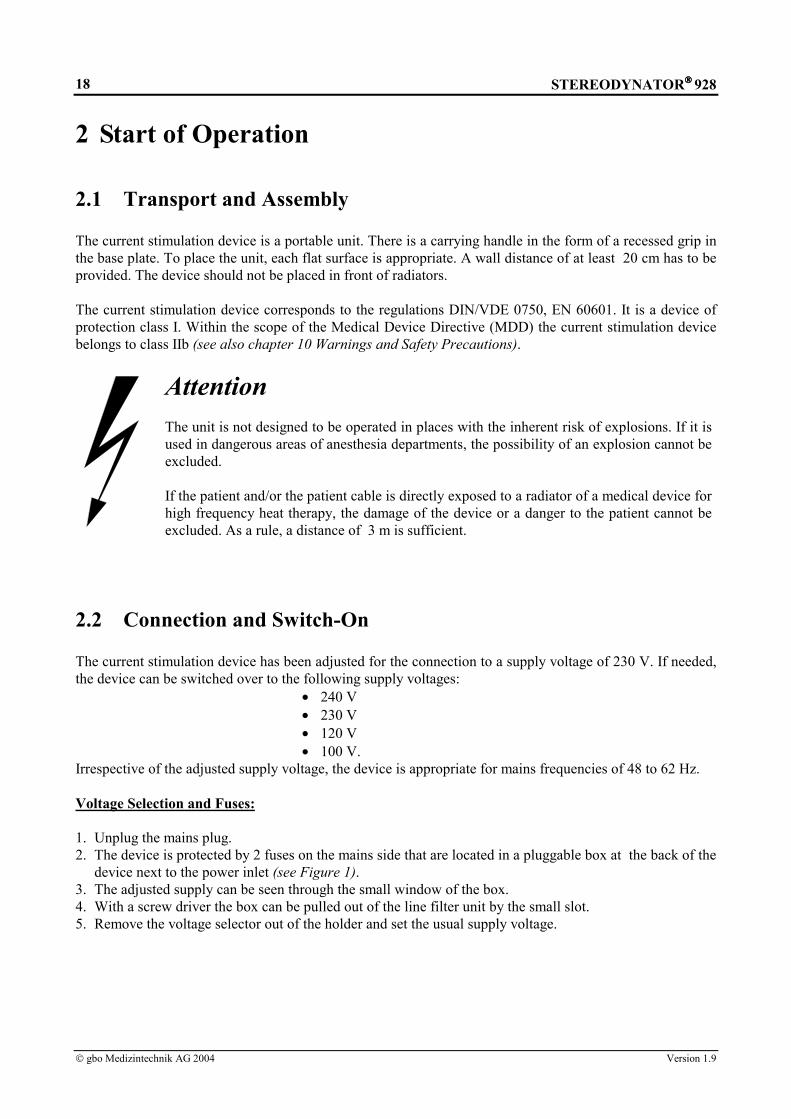
The current stimulation device is a portable unit. There is a carrying handle in the form of a recessed grip inthe base plate. To place the unit, each flat surface is appropriate. A wall distance of at least 20 cm has to beprovided. The device should not be placed in front of radiators.
The current stimulation device corresponds to the regulations DIN/VDE 0750, EN 60601. It is a device ofprotection class I. Within the scope of the Medical Device Directive (MDD) the current stimulation devicebelongs to class IIb (see also chapter 10 Warnings and Safety Precautions).
AttentionThe unit is not designed to be operated in places with the inherent risk of explosions. If it isused in dangerous areas of anesthesia departments, the possibility of an explosion cannot beexcluded.
If the patient and/or the patient cable is directly exposed to a radiator of a medical device forhigh frequency heat therapy, the damage of the device or a danger to the patient cannot beexcluded. As a rule, a distance of 3 m is sufficient.
2.2 Connection and Switch-On
The current stimulation device has been adjusted for the connection to a supply voltage of 230 V. If needed,the device can be switched over to the following supply voltages:
• 240 V• 230 V• 120 V• 100 V.
Irrespective of the adjusted supply voltage, the device is appropriate for mains frequencies of 48 to 62 Hz.
Voltage Selection and Fuses:
1. Unplug the mains plug.2. The device is protected by 2 fuses on the mains side that are located in a pluggable box at the back of the
device next to the power inlet (see Figure 1).3. The adjusted supply can be seen through the small window of the box.4. With a screw driver the box can be pulled out of the line filter unit by the small slot.5. Remove the voltage selector out of the holder and set the usual supply voltage.

STEREODYNATOR 928
gbo Medizintechnik AG 2004 Version 1.9
19
AttentionThe mains socket has been sealed with a scotch tape. This is to remember to checkprior to switch-on, whether the adjusted voltage corresponds to the supply voltage ofthe treatment room.
The scotch tape over the mains socket is easy to remove. Connect the current stimulation device with themains cable to a (grounded) safety power outlet.
The current stimulation device is switched on by the mains switch at the back of the device. By thisarrangement erroneous, unintended disconnection of the device during normal operations shall be avoided.
After switching on the device, an automatic selftest of all device functions will be performed (see chapter1.3 Short Instructions).
2.3 Settings
2.3.1 Device Settings
Once the unit has been switched on and is ready, you can start immediately with the standard settings.
Device settings Setting possibilities DeliverySignal for adjustment knob yes / no yesSignal for keys yes / no yesMax. value of therapy time 20 min / 40 min 20 minUltrasound power emission W / W/cm2 W/cm2
Automatic pump switch off yes / no YesSignal volume bargraph 0 - 15 7Language German
EnglishItalianPortugueseSpanishCzechFrench
German
Contrast of display 0 - 15 7Inverse representation yes / no NoDisplay mode of action yes / no yesTherapy time adjustment 1 min – max. value standardVacuum default intensity 0 % - 100 % 0 %
Table 2: Device settings

STEREODYNATOR 928
gbo Medizintechnik AG 2004 Version 1.9
20
If you would like to change them, please proceed as follows:1) Press the black Menu key.2) You are in the Main menu.3) Move the scroll bar with the Modification knob to Device settings.4) Confirm by pressing the white Soft key.5) You are in the Device settings menu.6) Move the scroll bar with the Modification knob to the device setting to be changed.7) Confirm by pressing the white Soft key.8) Move the cursor with the Modification knob to the desired value.9) Confirm by pressing the white Soft key.10) Exit the Device settings menu by pressing the black Menu key.11) On the display the Main menu appears again.
!! NoteOn Vacuum default intensity setting the pump is switched off, if no suction electrodes are connected.If suction electrodes are connected the pump will run corresponding to the set value.
2.3.2 Basic Settings of the Current Types
Upon pressing the desired current type key, the default settings for this current type are set. Alteredparameters are canceled by pressing the current type key again, i.e. the default settings are available again.Modifications will not be stored.
!! NoteIf the default settings for the therapy time have been modified by therapy time adjustment, the newsettings are permanently stored and recalled each time after pressing the current type key.

STEREODYNATOR 928
gbo Medizintechnik AG 2004 Version 1.9
21
3 Description of Function
3.1 Operating Notes
Each current type can be modified specifically. Certain modifications can be set only when the intensitycontrol is ”0.0”. Other modifications can be set also during therapy. Please observe the acoustical andoptical user support.
3.1.1 Optical and Acoustical User Support
Optical user support is furnished in the form of LEDs incorporated into the keys:
LED Condition of the keyFlashing key was selected and remains activeConstantly lit key is active and operationalnot lit key is not active and not operational
Table 3: Optical user support
Furthermore, optical user support is furnished on the display:
• A modification which is just being changed is shown inversely.• If in case of a current type Pulse duration T and/or Pause duration R are modifiable, only the letter T
and/or R will be shown under the current type diagram. The numerical values are shown next to thePulse duration key and/or Pause duration key, see Figure 12 and Figure 13.
• If in case of a current type Pulse duration T and/or Pause duration R are not modifiable, the numericalvalues are shown under the current type diagram.
Star display:
Interferenz
Figure 2: Three-ray star display
The three-ray star display has multiple functions and serves as stimulation frequency display and electrodecontact display. In case of single-circuit mode, the star display is switched off.
The green luminous bars indicate the stimulation frequencies. In case of the three-circuit mode, all three barsare lit. If stereodynamic interference current is applied, they show the beat frequencies effective in the body.The vertical bar shows the interference between circuit 1 and circuit 2, the left bar between circuit 2 andcircuit 3, and the right bar between circuit 1 and circuit 3.

STEREODYNATOR 928
gbo Medizintechnik AG 2004 Version 1.9
22
The red LEDs in the center of the star are lit, when current is flowing. Without current flowing, all red LEDsare turned off.
The following table explains the acoustic signals and their meaning: Type of signal Cause Confirmation ”beep” 1 × • in case of an admissible key operation Information sound 1 × • in case of an inadmissible key operation
• in case of disconnecting the patient plug duringoperation
Alarm approx. 2 s • in case of insufficient electrode contact and droppingelectrodes during therapy (CC)
• in case of unintended current increase during therapy(CV)
Triad gong 1 × 3 ×
• at the beginning of the automatic check to control thegong
• at the end of therapy• if in manual operation the key has not been pressed
for 2 min• if in ”CV” there was no current flows for 2 min
Table 4: Acoustical user support
3.1.2 Intensity Regulator
The Intensity regulator serves for setting the current intensity. It is furnished in the form of a incrementalencoder. The current increases by turning right (in + direction) and it is reduced by turning left (in -direction). The numerical value is shown on the display.
The current value can be set in the following steps:• Galvanic Current, Micro-Stimulus Current → 0.1 mA• all the rest of therapy current types → 0.5 mA.
!! Notes• The Intensity regulator automatically reverts to ”0.0” after the expiration of the therapy time.• When changing over from one current type to another, the Intensity regulator has to be set to
”0.0”. Control the current indication on the display.
3.1.3 Current and Polarity
On the display, both the peak value of the stimulation current in mA peak as well as the polarity + and/or –are shown. The polarity sign always refers to the red plug of the accessories. The polarity change over is notactive in case of biphase currents. When selecting biphase currents the polarity sign disappears.
+ / -mA peak
+ 12.5
Figure 3: Current indication on the display with the Polarity key
STEREODYNATOR 928
gbo Medizintechnik AG 2004 Version 1.9
23
Automatic pole changing:
By pressing the Polarity key polarity changes as follows:
1. Press → automatic pole changing, at first the polarity is positive (”+” flashes) and reverts to negative(”-” flashes) after half of the therapy time.
2. Press → polarity changes from positive to negative.3. Press → polarity is positive again.
When the polarity changes, the current will be faded out and restored again within 10 s. In case ofcombination of the current types DF and CP, polarity will be changed after half of the therapy time.
!! Notes• The automatic pole changing can only be set before starting the therapy.• During therapy however, the polarity can be changed by pressing the Polarity key. By this, the
current will also be faded out and restored again within 10 s.
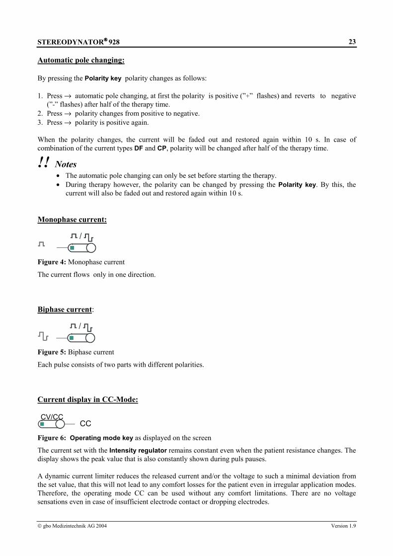
Monophase current:
/
Figure 4: Monophase current
The current flows only in one direction.
Biphase current:
/
Figure 5: Biphase current
Each pulse consists of two parts with different polarities.
Current display in CC-Mode:
CV/CCCC
Figure 6: Operating mode key as displayed on the screen
The current set with the Intensity regulator remains constant even when the patient resistance changes. Thedisplay shows the peak value that is also constantly shown during puls pauses.
A dynamic current limiter reduces the released current and/or the voltage to such a minimal deviation fromthe set value, that this will not lead to any comfort losses for the patient even in irregular application modes.Therefore, the operating mode CC can be used without any comfort limitations. There are no voltagesensations even in case of insufficient electrode contact or dropping electrodes.

STEREODYNATOR 928
gbo Medizintechnik AG 2004 Version 1.9
24
Display in CV-Mode:
CV/CCCV
Figure 7: Operating mode key as displayed on the screen
Constant voltage is set with the Intensity regulator. The value of the current to the patient depends on thepatient resistance. The value of the Voltage is shown in V peak.
!! Note In CV-Mode the intensity will be shown in V peak not in mA peak.
3.1.4 Surge Parameters
Some current types can be surged individually by a surge cycle. The three surge parameters
rise time
duration time
pause time
determine a surge cycle. Each surge parameter can be changed within 0 to 60 s in steps of 0.5 s. The descenttime in each surge cycle is always set to 1 s constantly.
s s s2 3 6
Figure 8: Surge parameter key with the according displays
3.1.5 Galvanic Base
Basisautom 0 %
Figure 9: Galvanic Base key with its display
The current types DF, CP, MF and LP can be underlayed by a d.c. current whose amplitude corresponds to20 % and/or 50 % of the peak current. By repeatedly pressing the key it can be changed between 0 %, 20 %and 50 % of the d.c. current underlaying. This is shown on the display.
3.1.6 Frequency Lock
FIXFrequency
Hz
53 10
Figure 10: FIX key with the display of the fixed therapy frequency

STEREODYNATOR 928
gbo Medizintechnik AG 2004 Version 1.9
25
In case of frequency modulated current types, the frequency can be locked and released with this key duringthe treatment. The first key pressure locks, another actuation releases the frequency.
!! NoteIf you want to modify the frequency, please press the white Soft key [[[[frequency]]]]. The frequency nowcan be modified step by step with the modification knob. The frequency can be modified by turningthe modification knob. Herewith also changes the pulse and/or pause duration. The according timeschange in the current type display and will not be shown by the T and/or R display.
3.1.7 Pulse Parameter
Pulse rise:
Figure 11: Pulse rise key as displayed on the screen
The stimulation impulses can be modified in 5 steps to a rectangular, trapecoidal or triangular shape.
Setting possibilities for the pulse duration and pause duration:
ms4.0
T
ms16
R
Figure 12: Pulse duration key as displayedon the display
Figure 13: Pause duration key as displayed on thedisplay
Pulse duration T and pause duration R can be modified before and during the treatment:• If in case of a current type Pulse duration T and Pause duration R are modifiable, only T and R will be
shown under the current type diagram. The numerical values are shown above the Pulse duration keyand/or the Pause duration key.
• If in case of a current type Pulse duration T and Pause duration R are not modifiable, the letters T andR will be shown with the according numerical values under the current type diagram.
• The pulse and/or pause duration can be modified via the frequency by pressing the FIX key. Theaccording times change in the diagram and are not shown above the T and/or R keys.
• If for pulse duration T or pause duration R there have been set higher values than 9000 ms, the unit willchange from ms to s.
3.1.8 Therapy Time
05:00Min Sec
0 10 20 30
Therapy Timer
Figure 14: Therapy time key as displayed on the display

STEREODYNATOR 928
gbo Medizintechnik AG 2004 Version 1.9
26
You can set the therapy time as follows:1. Depending on the current type an appropriate therapy time will be suggested.2. If you want to change the therapy time, press the Therapy time key. The time can be modified in steps of
1 minute. The maximum therapy time to select is 40 min (see chapter 2.3.1 Device Settings).3. Set the desired therapy time:
• By repeatedly pressing the Therapy time key or• By using the Modification knob.
!! Notes• The selected or given therapy time passes only if the Intensity regulator is turned out of its ”0.0”
position.• The therapy time can be modified during the treatment.• At the end of the therapy time the stimulation current to the patient will be faded out automatically
within 10 s:∗ The Intensity automatically reverts to ”0.0” after cutting off the stimulation current to the
patient.∗ The selected current type and possible modifications will be kept.∗ The therapy time setting remains on 0 min.∗ The triad gong sounds 3 times (see also Table 4: Acoustical user support).∗ The therapy can be continued by setting a new therapy time and turning on the intensity.∗ Pressing again the same current type key leads to the basic setting of this current type.
3.1.9 Stimulation shifting
endex I
endex II
Figure 15: stimulation shifting keys
In the basic setting, the stereodynamic interference currents are endogenous, that means they have an intenseeffect.
The stimulation effect can be shifted towards electrode I (or II) by pressing the end ex I key (or end ex IIkey). By that, the stereodynamic interference currents are exogenous, that means that the stimulating effecttakes place on the body surface. As the following figure shows, the actual status of stimulation shifting isindicated below the current type.
!! Notice The stimulation shifting can not be switched over during therapy.

STEREODYNATOR 928
gbo Medizintechnik AG 2004 Version 1.9
27
Figure 16: Stimulation shifting switched off
3.1.10 Menu
MenüMenu key - The black Menu key serves for calling the menus.
Soft key – Within the menu, the white Soft key serves as a confirmation key.
Figure 17: Menu key and Soft key
A soft key is a key with a context-sensitive meaning. The according meaning of the key is shown on thedisplay right next to the key.
The main menu puts the following menus at your disposal:
• Special current types, see chapter 4.5• Programs, see chapter 3.1.11• Application with Electro Therapy, see chapter 4.2• Application with ultrasound, see chapter 4.3• Device settings, see chapter 2.3.1

STEREODYNATOR 928
gbo Medizintechnik AG 2004 Version 1.9
28
3.1.11 Menu Programs
Besides the current types, which are already stored in the device, there is a possibility to create your ownprograms of current types and to store and select them.
Program and store a current type:
1. Select the desired current type.2. Select all desired modifications.3. Press the Menu-key.4. Move the cursor by means of the modification knob to Programs.5. Select by pressing the Soft key [select].6. The cursor points to store program.7. Select by pressing the Soft key [store].8. Move the cursor by means of the modification knob to the wanted storage location Program NN.9. Select by pressing the Soft key [store].10. The device exits the menu and returns to the current type.
Select a stored current type program:
1. Press the Menu-key.2. Move the cursor by means of the modification knob to Programs.3. Select by pressing the Soft key [select].4. The cursor points to store program.5. Move the cursor by means of the modification knob to the wanted storage location Program NN.6. Select by pressing the Soft key [select].7. The device exits the menu and returns to the current type.

STEREODYNATOR 928
gbo Medizintechnik AG 2004 Version 1.9
29
3.2 Integrated Suction Application Aid
The suction application aid is optionally available. The operating elements for the suction application aid areintegrated on all membrane keyboards.
!! Note The suction application aid cannot be used during diagnostic programs.
Vac
Figure 18: Vacuum key Figure 19: Vacuum-Intensity key Figure 20: Suction massage key
1. Press the Vacuum key, the pump will be switched on. The basic pressure is immediately available.2. Press the Vacuum-Intensity key and set the vacuum intensity with the Modification knob or by
repeated pressure of the key, so that the suction electrodes can be comfortably applied to the patient.The vacuum intensity is shown on the display in the form of a cylinder diagram.
!! Notes• The operating mode CC can be used without any comfort limitations; there are no voltage
sensations even in case of dropping electrodes.• In case of the galvanic mode the maximum admissible output current will be limited to 20 mA
when suction electrodes are used to prevent cauterization.• In case of the galvanic mode the current density must not exceed 0.2 mA/cm2 (see also Table
5).
3. Press the Vacuum massage key and set the suction massage frequency:• By repeatedly pressing the Vacuum massage key or• By turning the Modification knob.
!! NoteThe vacuum frequency can be modified in steps of 5 pulses/minute within the range of 0 to 60pulses/minute.
4. If upon switching on the vacuum application no current is applied for 2 min or if the therapy time hasexpired since 2 min, the pump automatically switches off, provided that this has been activated in theDevice settings menu, see chapter 2.3.1.
For the different suction electrodes, the following current values must not be exceeded when galvaniccurrent is applied:
Suction electrode Size Current valueElectrode plate small 6 cm2 1.2 mAElectrode plate standard 12 cm2 2.4 mAElectrode plate large 28 cm2 6 mA
Table 5: Current values of the suction electrodes in case of galvanic mode

STEREODYNATOR 928
gbo Medizintechnik AG 2004 Version 1.9
30
3.3 Ultrasound Therapy Module
Depending on the device configuration, the ultrasound therapy module is either optional or standard. Theoperating elements have already been integrated on the membrane keyboard.
Comb Sono
Figure 21: Comb key (1/3 MHz) Figure 22: Sono key (1/3 MHz)
Watt
Figure 23: Continous/Pulsed key Figure 24: Ultrasound power key
!! Notes• The ultrasound frequency can be changed to 1 or 3 MHz.• The frequency for pulsed mode 100 Hz.• The pulse parameters are 1:5, 1:10 or 1:20.• The coupling status of the probe is shown by an LED on the probe housing. The LED will be off in
case of insufficient coupling. The LED will be flashing in case of good contact.• As a standard setting the ultrasound power is shown in W/cm2 on the display. In the device settings
(see chapter 2.3.1) you can select between the formats W and W/cm2 .• If you want to exit the ultrasound operation prematurely, i.e. before expiration of the therapy time,
press the Sono- and/or Comb key again.
Attention• Do not forget the contact gel!• Be careful with the ultrasound probe, because rough external influences such as a
mechanical shock or impact can alter its characteristics. We recommend to carry out avisual examination at least once a year to check for fissures that allow liquids to enter, aswell as regarding the integrity of the cables and connectors.
Power for5 cm2 ultrasound probe 2,5 cm2 ultrasound probe
1 MHz Continuous wave 0.5 to 15 W 0.1 to 3 W/cm2 0.1 to 7,5 W 0.1 to 3 W/cm2
1 MHz impulse wave 0.5 to 15 W 0.1 to 3 W/cm2 0.1 to 7,5 W 0.1 to 3 W/cm2
3 MHz Continuous wave 0.1 to 7,5 W 0.1 to 1.5 W/cm2 0.1 to 2.5 W 0.1 to 1.5 W/cm2
3 MHz impulse wave 0.1 to 7,5 W 0.1 to 1.5 W/cm2 0.1 to 2.5 W 0.1 to 1.5 W/cm2
Table 6: Setting possibilities of the ultrasound power, increments are shown in bold.
For combined operation we recommend the following procedure:
1. Select the current type.2. Set the desired modification.3. Select the operation mode „Combined Operation“ by pressing the Comb key.

STEREODYNATOR 928
gbo Medizintechnik AG 2004 Version 1.9
31
4. By pressing the Comb key once you reach the ultrasound frequency 1 MHz. By pressing the Comb keytwice you reach the ultrasound frequency 3 MHz.
5. Set the desired modification.6. In case of this operation mode the blue plug of the patient cable is currentless. In the basic setting the
red plug has positive polarity, whereas the backplate electrode – the metallic ultrasound probe surface –is negative.
7. Connect the red plug of the patient cable with the neutral electrode.8. Apply the neutral electrode.9. By pressing the Continous/Pulsed key select the pulse wave 1:5, 1:10, 1:20 or continuous wave. The
current impulse type is shown on the display.10. Press the Ultrasound power key and set the ultrasound power:
• By repeatedly pressing the Ultrasound power key or• By turning the Modification knob.
11. Put the ultrasound probe on the patient’s treatment area (important: contact gel !!) and move it slowly.12. Set the current intensity by turning the Intensity regulator. If the patient experiences a pain, reduce the
stimulation intensity.
!! Notes• By combined operation the therapy time will pass if the Intensity regulator is turned and / or the
ultrasound probe has been coupled to the patient.• Combined operation is only possible in CV-Mode, since the ultrasound probe can be moved and/or
removed during the therapy.• Due to the acidification of the contact gel, the ultrasound therapy cannot be operated with the
Galvanic current type.• In combined operation it is not possible to apply the electrode handpiece.• The current density should not exceed 2 mA/cm2 .
For pure ultrasound operation we recommend the following procedure:
1. Select the operation mode by pressing the Sono key.2. By pressing the Sono key once you reach the ultrasound frequency 1 MHz. By pressing the Sono key
twice you reach the ultrasound frequency 3 MHz.3. The therapy time will be set to 10 minutes.4. If needed, modify the therapy time.5. By pressing the Continous/Pulsed key select the pulse wave 1:5, 1:10, 1:20 or continuous wave. The
current impulse type is shown on the display.6. Press the Ultrasound power key and set the ultrasound power:
• By repeatedly pressing the Ultrasound power key or• By turning the Modification knob.
7. Put the ultrasound probe on the patient’s treatment area (important: contact gel !!) and move it slowly;now the therapy time passes.
!! NoteIf the ultrasound probe has not been coupled to the patient, no therapy time will pass. When the probehas been coupled again, the therapy time will continue to pass. Hence, the ultrasound probe can beremoved in between.
STEREODYNATOR 928
gbo Medizintechnik AG 2004 Version 1.9
32
4 Therapy
4.1 Therapy with interference currents
Upon switching on the electrical stimulus device and its automatic check, the interference current Sedat willalways appear with its basic setting, if multipolar electrodes are connected. In addition, the Menu forinterference currents is available.
If there are no or single circuit electrodes connected, the single circuit therapy current DF appears and theMenu for single circuit therapy currents is available.
!! Notice• Interference currents can only be applied with constant voltage (mode CV).• The frequency ranges are passed in a minute’s rhythm.• During therapy, you can switch over between interference currents, but not between the automatic
programs.• For visually handicapped, interference current Sedat can be dubbed with a signal
Generally, there is the following procedure for therapy with interference current:
1. Connection through the mains switch at the back of the device.2. The device executes an automatic check of all functions.3. The faultless automatic check ends with the acoustic signal.4. Connect the accessories for interferential currents with the according socket on the right side of the
device.5. Interference current Sedat is available with its basic settings.6. Apply the electrodes on the patient.7. Select the required interference current by repeatedly pressing the Interference current key or the
required automatic program by pressing the respective Program key or selecting from Menu →→→→Programs.
8. Set the required modification.9. Turn the Intensity regulator slowly, until the current is clearly perceptible, but do not generate any
muscular contracture.• The luminous bars of the stimulation frequency display move in the rhythm of the stimulation
frequencies.• Three red lights must be lit in the center of the stimulation frequency. This is a control display for
the correct electrode contact: one red light has been assigned for each current circuit whichextinguishes in case of faulty electrode contact in its current circuit.
10. At the end of the therapy the triad gong will sound three times and intensity automatically reverts to„0.0“.
4.1.1 Sedat
The interference current Sedat (200 Hz) has an analgesic effect and at the same time a sedative effect on theNervus sympathicus; by this, it indirectly stimulates the blood flow in case of hypertonia of the vascularwalls. Almost all therapies of painful functional disturbances can be initiated with this frequency. The firstinterference current that appears is Sedat.

STEREODYNATOR 928
gbo Medizintechnik AG 2004 Version 1.9
33
4.1.2 Myomot
Interference current Myomot (50 Hz) stimulates the skeletal muscles. The dynamics of the area beingstimulated and of the intensity generate a special physiological kind of muscle contraction. As opposed tothe classical method, the individual muscle fibers are activated alternately. By this, a fatigue effect throughcontinuous contractions is avoided. Proceed as indicated in chapter 4.1. You must press the Interferencecurrent key twice !
4.1.3 Vegetative Stimulation I
Interference current Vegetat. Stim. I (2.5 Hz bis 25 Hz) leads to normal tonus of the vegetative nerve system,accompanied by vibrations. This frequency range is also indicated in case of peripheral venous circulatorydisturbances and blockings. The rhythmical muscle contractions press out the contents of veins. In addition,with low frequencies there is a stimulation of the sympathic nervous system (Lullies). Proceed as indicatedin chapter Kapitel 4.1. You must press the Interference current key three times !
4.1.4 Vegetative Stimulation II
Interference current Vegetat. Stim. II (10 Hz) leads to a normal tonus of the vegetative nerve system,accompanied by a „shaking“. Ankyloses and muscular contractions can be mobilized. Proceed as indicatedin chapter 4.1. You must press the Interference current key four times !
4.1.5 Vegetative Stimulation III
Interference current Vegetat. Stim. III (0.1 bis 1 Hz) leads to a normal tonus of the vegetative nerve systemand it is often combined with Sedat. Individual muscle contractions can be generated. Proceed as indicatedin chapter 4.1. You must press the Interference current key five times !
4.1.6 Universal
Interference current Universal contains the therapy frequencies from 1 to 200 Hz. Proceed as indicated inchapter 4.1. You must press the Interference current key six times !
4.1.7 Sedation Modulation
Interference current Sedation Modulation contains the therapy frequencies from 100 to 200 Hz. Proceed asindicated in chapter 4.1. You must press the Interference current key seven times !

STEREODYNATOR 928
gbo Medizintechnik AG 2004 Version 1.9
34
4.1.8 Automated programs
The electrical stimulus device is equipped with five automated programs to facilitate the adjustment oftherapy frequencies and times. If you press the respective Program key (programs A,B and C) or select inthe Menu the menu entry Programs (programs D and E), the programs indicated in the table below willautomatically run. If you wish to select the programs D and E, proceed as indicated in chapter Menu specialtypes of current.
ProgA
ProgB
ProgC
Figure 25: Program keys
Automated Therapy time EffectsProgram 3 min 10 min 2 min
A 200 Hz (Sedat) 50 Hz(Myomot)
200 Hz (Sedat) analgesia,hyperemia,muscle stimulation
B 200 Hz (Sedat) 2.5 - 25 Hz(Vegetat. Stim. I)
200 Hz (Sedat) analgesia,venous relaxation,hyperemia
C 200 Hz (Sedat) 10 Hz(Vegetat. Stim. II)
200 Hz (Sedat) analgesia, hyperemia,mobilization of ankyloses andmuscular contractions
D 200 Hz (Sedat) 0.1 - 1 Hz(Vegetat. Stim. III)
200 Hz (Sedat) analgesia,hyperemia,vegetative stimulation
E 200 Hz (Sedat) 1 Hz(Vegetat. Stim. IV)
200 Hz (Sedat) analgesia,hyperemia,vegetative stimulation
Table 7: Automated programs
Proceed as indicated in chapter 4.1.
!! Notices• The therapy time of an automated program always takes 15 minutes and cannot be modified.• During therapy it is not possible to switch over between the automated programs.• The three types of interference currents are shown on the current type window of the display. The
actual type of current is clearly displayed: Sedat - Vegetat.Stim. III - Sedat.
• In case of the automated programs, frequency cannot be stopped.

STEREODYNATOR 928
gbo Medizintechnik AG 2004 Version 1.9
35
4.2 Menu Application With Electrotherapy
This menu driven additional program facilitates stimulation therapy by selecting area of application andmode of action.
1) Press the Menu key.2) Move the scroll bar/cursor with the Modification knob to Application with electrotherapy .3) Confirm by pressing the white Soft key.4) Move the scroll bar/cursor with the Modification knob to the desired application area:
• Head & Neck• Vertebral column & Trunk• Upper extremities• Lower extremities
5) Confirm by pressing the white Soft key.6) A list of the modes of action appears on the display:
• Analgesia• Hyperemia• Muscle toning• Muscle detoning
7) Move the scroll bar/cursor with the Modification knob to the desired mode of action.8) Confirm by pressing the white Soft key.9) The notes of application referring to the application area and the mode of action are shown on the
display.10) Apply the electrodes in accordance to the suggestion given, as long as there are not any contra-
indications.11) Confirm by pressing the white Soft key.12) If necessary, modify the therapy time.13) Turn on the Intensity regulator and therapy starts.
!! Notes• Only the therapy time can be modified!• If there are suction electrodes connected, the vacuum pump will be automatically switched on, that
means that it is not necessary to press the Vacuum key to switch on.
AttentionThe current type DF for Hyperemia has a d.c. portion. Therefore a certain currentdensity of 0.31 mA/cm2 (corresponds to 64 % d.c. portion of the peak value) should notbe exceeded. Depending on the electrode size there are the following current values:
Rubber electrode small 3 x 4 cm2 3.7 mARubber electrode standard 6 x 8 cm2 15 mARubber electrode large 8 x 12 cm2 29 mA
Suction electrode small (6 cm2) 1.9 mASuction electrode standard (12 cm2) 3.6 mASuction electrode large (28 cm2) 8 mA

STEREODYNATOR 928
gbo Medizintechnik AG 2004 Version 1.9
36
4.3 Menu ‘Applications with ultrasound’Tthe additional program Menu includes the Application with ultrasound for the single circuit therapy. Theprocedure is described correspondingly in the previous chapter. The only difference is by point 6 thereappears a list of indications not a list of modes of action.
4.4 ”One - Touch” - OperationThe following therapy current types are assigned to keys on the membrane keyboard:
DF Diadynamic current (diphasé fixe)CP Diadynamic current (modulé en courtes périodes)SMS Strong muscle stimulation according to EichhornMF I to VII Middle frequency I to VIIUR Ultrastimulation currentHV I to V High voltage I to VGalv Galvanic currentF1 Faradic currentTENS I to V Transcutaneous electric nerve stimulation I to VTENS Burst I to V Transcutaneous electric nerve stimulation in impulse groups
I to VMicro Micro-stimulus currentT/R Universal - Therapy
Chapter 4.1 is also valid correspondingly for the therapy with single circuit currents. The procedure for thesingle circuit therapy is as follows, as far as it has not been described otherwise:1) Put the electrodes on to the patient (see chapter 7.1 Electrode ).2) Connect the accessories with the according socket on the right side of the device.3) Select the current therapy type by pressing the according Current type key or by selecting the Special
current types menu or by selecting the Application menu.4) Set the required modifications.5) Turn on the Intensity regulator up to the sensitive tolerance limit (as far as it has not been described
otherwise).6) The intensity of current is shown on the display.7) At the end of therapy time the triad gong will sound three times.
!! Notes• Before switching over from one current type to another you have to set the Intensity regulator to
„0.0“.• At the beginning, the polarity of mono-polar current types is always positive.• For the visually handicapped the multiple allocation keys can be dubbed with a signal for the first
current type (MF key, HV key, Tens key and Tens-Burst key) (see chapter 2.3.1).• In the case of multiple allocation of the current type keys, the LED flashes during the selection of
the according currents. This shows that the key remains active.
4.4.1 Diadynamic Currents
The current type DF serves for the treatment of sympathicotonic states, e.g. spastic circulatorydisturbances. It produces a local analgesia in the area to be treated. With it e.g. the symptoms hardening →pain → hardening can be eliminated for a while.
STEREODYNATOR 928
gbo Medizintechnik AG 2004 Version 1.9
37
The current type CP is suited very well for the treatment of functional disturbances of the locomotionsystem, circulatory disturbances, neuralgia and radiculopathies. It is mostly applied after the DF program,but it is also possible the other way round.
Therapy with the combination of the current types DF and CP:
1. Press the DF key.2. Set the desired modifications for DF.3. On the display there appears [combination with CP] next to the Soft key.4. Select the combination mode by pressing the Soft key.5. Set the desired modifications for CP.6. Turn the Intensity regulator to the sensitive tolerance limit.7. On the display the selected current type and the total therapy time are shown.
!! Notes• When changing from one current type to another, the first current will be faded out within 10 s and
then the second one will rise within 40 s to 80 % and within further 20 s to 100 % of ist intensity.• A maximum of two current types can be combined in sequence.
4.4.2 Strong Muscle Stimulation (SMS) According to Eichhorn
In case of long-lasting, chronic muscle detriments the muscular apparatus can be built up again with SMS.Visible and palpable continuous muscular contractions will be caused, whereas the patients tolerate higherintensities of current due to biphase stimulation impulses.
The current type SMS consists of a biphase rectangular pulse with a pulse duration of 10 ms and a pauseduration of 100 ms.
4.4.3 Middle Frequency Currents
The middle frequency currents are applied in case of diseases and injury sequels of the locomotion andsupporting system, especially also in the wide rheumatic area.
There are seven middle frequency currents available. By repeatedly pressing the MF key you can switchfrom MF 1 to MF VII.
Surged middle frequency MF I:
The surged middle frequency current MF I has a rise time of 2.0 s, a duration time of 3.0 s and a pause timeof 6.0 s in the basic setting.
Sinus surged middle frequency MF II:
The current type MF II is a sinus surged middle frequency current.

STEREODYNATOR 928
gbo Medizintechnik AG 2004 Version 1.9
38
Middle frequency with fix therapy frequencies MF III:
As a basic setting of the current type MF III a middle frequency current of 50 Hz is offered. In this, thecurrent has a rise time of 2.0 s, a duration time of 3.0 s and a pause time of 6.0 s for the surge.
!! Notes• The pause duration R can be modified with the Pause duration key and/or the modification
knob. Hence an adjustable frequency range of 0.1 - 200 Hz is possible.• The frequency adjusted with the pause duration is shown on the display.• By turning the Intensity regulator the adjusted fix frequency will be taken over.
Frequency modulated middle frequencies MF IV - MF VII:
In case of the frequency modulated middle frequency currents, the therapy always starts with the lowerfrequencies, whereas the frequency ranges will be passed twice within 15 s. In case of MF IV to MF VIpulse and pause duration vary. In case of the middle frequency current MF VII only the pause duration Rvaries. Pulse duration T will remain constant.
1. Press the MF key in accordance to the desired middle frequency.2. The frequency range will be shown on the display.3. Set the desired modifications.4. The therapy is started by turning the Intensity regulator.5. The intensity of the current will be shown on the display.6. The frequency traverse can be stopped by pressing the FIX key.7. The fixed frequency will be shown on the display.8. The therapy time continues to pass.9. Press the white Soft key [frequency].10. The frequency can be readjusted by turning the Modification knob.11. Press the FIX key again.12. The frequency traverse will be released again.13. The triad gong will sound three times after the expiration of the therapy.
4.4.4 Ultrastimulation Current
The ultrastimulation current UR is applied in case of pain and muscle spasms, peripheral circulatorydisturbances and for producing isometric muscle contractions.
!! Notes• In case of patients with high current sensitivity apply the biphase mode.• Do not cause any continuous muscular contractions!
4.4.5 High-Voltage Currents
The high-voltage therapy includes diseases of the muscular, ligament and skeleton systems, peripheralnerves, circulatory disturbances and the detection of ”trigger-points”.

STEREODYNATOR 928
gbo Medizintechnik AG 2004 Version 1.9
39
As the stimulation impulses are biphase, there do not exist any electrolytic side effects under thestimulation electrodes. Negative and positive impulses have the same energy; therefore, a treatment in thearea of metallic implants is possible.
There are five high-voltage currents available. You can change from HV I to HV V by repeatedly pressingthe HV key.
High voltage with fix therapy frequencies HV I:
In the basic setting, the high-voltage current type HV I has a rise time of 2.0 s, a duration period of 3.0 s anda pause time of 6.0 s with a frequency of 50 Hz.
!! Notes• The pause time R can be modified with the Pause duration key and/or the Modification knob.
Hence an adjustable frequency range of 0.1 - 200 Hz is possible.• The fix frequency adjusted with the pause duration will be shown on the display.• The adjusted frequency will be taken over by turning the Intensity regulator.
Frequency modulated high-voltage current HV II - HV V:
In case of the frequency modulated high-voltage currents, the therapy always starts with the low frequencies,whereas the frequency ranges will be passed twice within 15 s.
1. Press the HV key in accordance with the desired high-voltage current types.2. The frequency range will be shown on the display.3. Set the desired modifications.4. The therapy is started by turning the Intensity regulator up to the sensitive tolerance limit.5. The intensity of the current will be shown on the display.6. The frequency traverse can be stopped by pressing the FIX key.7. The fixed frequency will be shown on the display.8. The therapy time continues to pass.9. Press the white Soft key [frequency].10. The frequency can be readjusted by turning the Modification knob.11. Press the FIX key again.12. The frequency traverse will be released again.13. The triad gong will sound three times after the therapy time expires.
4.4.6 Galvanic Current and Iontophoresis
The galvanic current is used to stimulate the circulation in the area to be treated. It has alleviatingcharacteristics and can be recommended as a preparing measure for electrogymnastics (see chapter 4.4.7).
Furthermore, with iontophoresis it serves for percutaneous penetration of drugs. Here the procedure is thesame as in case of galvanization. The quantity of the penetrated drug depends on the purity of its solution,the size of the electrodes, the intensity of current, the polarity and the penetration time. The knowledge ofthe loading of the drug is especially important for a successful treatment. Acids are always transported to theanode, bases to the cathode.

STEREODYNATOR 928
gbo Medizintechnik AG 2004 Version 1.9
40
!! Notes• Turn the Intensity regulator only until the patient notices a slightly increasing current.• Apply the intermediate layers dripping wet.• In case of anode-effective drugs the layer of the anode will be saturated with the solution of the
drug, and in case of cathode-effective drugs the same is made with the layer of the cathode.• The electrode layers have to be washed out thoroughly after the expiration of ionthophoresis.
There should not remain any residuals (see chapter 9.2.2).
Attention • In case of iontophoresis do not exceed the intensity of current of 0.1 mA/cm2
(active) electrode surface.• In case of galvanization do not exceed the intensity of current of 0.2 mA/cm2
(active) electrode surface.• The patient must not feel a burning .
4.4.7 Faradic Current
Neofardic currents are applied for electrogymnastics of the faradising or restimulating muscles. This appliesespecially for atrophies due to inactivity after longer periods of inactivity and for post operationelectrogymnastics to avoid thromboses.
!! Note Turn the Intensity regulator until the stimulation effect becomes obvious.
4.4.8 Transcutaneous Electrical Nerve Stimulation
The TENS current types are applied in case of chronic and also acute pain syndromes such as the postoperative pain, birth pain and acute post traumatic and rheumatic pain. This includes neurological, internal,surgical, traumatological, orthopedic, sports medicine and gynecological areas.
There are five current types available. You can change from TENS I to TENS V by repeatedly pressing theTens key.
TENS with fixed therapy frequency TENS I:
The current type TENS I has a frequency of 100 Hz and a pause duration R of 10 ms in its basic setting.
!! Notes• Pause duration R can be modified with the Pause duration key and/or the Modification knob.
Hence an adjustable frequency range of 0.1 - 1400 Hz is possible.• The fixed frequency adjusted with pause duration will be shown on the display.• The fixed frequency will be taken over by turning the Intensity regulator.

STEREODYNATOR 928
gbo Medizintechnik AG 2004 Version 1.9
41
Frequency modulated TENS II - TENS V:
In case of the current types TENS II - TENS V the pause duration R will alter within certain areas and thepulse duration will remain constant at 0.2 ms. The therapy always starts with the low frequencies, whereasthe frequency ranges will be passed twice within 15 s.
1. Press the Tens key in accordance to the desired current type.2. The frequency range will be shown on the display.3. Set the desired modifications.4. The therapy is started by turning the Intensity regulator.5. The intensity of the current will be shown on the display.6. The frequency traverse can be stopped by pressing the FIX key.7. The fixed frequency will be shown on the display.8. The therapy time continues to pass.9. Press the white Soft key [frequency].10. The frequency can be readjusted by turning the Modification knob.11. Press the FIX key again.12. The frequency traverse will be released again.13. The triad gong will sound three times after the expiration of the therapy time.
4.4.9 Transcutaneous Electrical Nerve Stimulation With Impulse Groups
The application area of TENS Burst currents is very similar to that of TENS currents, but with a lessanalgesic but more detoning effect.
There are five current types available. You can go from TENS Burst I to TENS Burst V by repeatedlypressing the Tens-Burst key.
TENS Burst with fix therapy frequencies TENS Burst I:
The current type TENS Burst I has a frequency of 50 Hz and a pause duration R of 18 ms in its basic setting.
!! Notes• Pause duration R can be modified with the Pause duration key and/or the Modification knob.
Hence an adjustable frequency range of 0.1 - 400 Hz is possible.• The fixed frequency adjusted with the pause duration will be shown on the display.• The fixed frequency will be taken over by turning the Intensity regulator.
Frequency modulated TENS Burst II - TENS Burst V:
In case of the current types TENS Burst II - TENS Burst V the pause duration R will alter within certainranges and the pulse duration T remains constant at 2 ms. The therapy always starts with the lowfrequencies, whereas the frequency ranges will be passed twice within 15 s.
1. Press the Tens-Burst key in accordance to the selected current type.2. The frequency range will be shown on the display.3. Set the desired modifications.4. The therapy will be started by turning the Intensity regulator.5. The intensity of current will be shown on the display.6. The frequency traverse can be stopped by pressing the FIX key.

STEREODYNATOR 928
gbo Medizintechnik AG 2004 Version 1.9
42
7. The fixed frequency will be shown on the display.8. The therapy time continues to pass.9. Press the white Soft key [frequency].10. The frequency can be readjusted by turning the Modification knob.11. Press the FIX key again.12. The frequency traverse will be released again.13. The triad gong will sound three times after the expiration of the therapy time.
4.4.10 Micro-Stimulus Current
Micro-stimulus current is applied in kinds and stages of diseases, as well as in injury consequences, forwhich depth warming seems to be a successful therapy. It includes surgical, traumatological, orthopedic,sports medicine and gynecological areas.The impulse sequences of the micro-stimulus current have an extremely low intensity, which amounts to 5mA maximum.
!! NoteThe pulse duration and pause duration can be adjusted only within a limited range. The maximumperiod duration is 50 ms.
4.4.11 Universal Therapy
The basic setting of the Universal therapy T/R is especially suited for the application in case of severeparalyses. Pulse duration and pause duration are adjustable within wide limits for middle and mild paralyses.
4.5 Special types of current Menu
Some current types cannot be selected by key but within the menu. The user support is driven by dialog onthe display.
The following therapy current types are filed in the Special types of current menu:IG 30 Impulse galvanization with 30 ms single-pulse durationIG 50 Impulse galvanization with 50 ms group-pulse durationFM Frequency modulationMF Diadynamic current (monophasé fixe)LP Diadynamic current (longues périodes)Incontinence Rectangular current for incontinence
1. Press the Menu key.2. Move the scroll bar/cursor with the Modification knob to Special types of current.3. Confirm by pressing the white Soft key.4. The content of the display will be shown inversely, to indicate that you are in the Special types of
current menu.5. Move the scroll bar/cursor with the Modification knob to the desired special current type.6. Confirm by pressing the white Soft key.

STEREODYNATOR 928
gbo Medizintechnik AG 2004 Version 1.9
43
7. The selected current type will be shown on the display.8. Set the desired modifications.9. Turn on the Intensity regulator and therapy will be started.
4.5.1 Impulse Galvanization
The impulse galvanization currents are so-called shaking frequency currents. Hyperemia, analgesia anddetoning are the main fields of application.
The current type IG 30 consists of triangular impulses with a pulse duration T of 30 ms and a pause durationR of 50 ms.
The current type IG 50 consists of rectangular impulses with a pulse duration of 1 ms and a pause durationof 19 ms (50 Hz). The rectangular impulses are released in groups with a pulse duration T of 50 ms and apause duration R of 70 ms.
4.5.2 Frequency Modulation
Frequency modulation is suited for electrostimulation of the muscles. The frequency modulation FMconsists of rectangular impulses. The frequency range will be passed twice within 6 s.
4.5.3 Diadynamic Currents MF Monophasé Fixe and LP Longues Périodes
The diadynamic currents monophasé fixe (MF) and longues périodes (LP) are used in pain therapy, forstimulating blood circulation, stimulating absorption (post Trauma) and for neuromuscularelectrostimulation.
AttentionDo not mistake the current type monophasé fixe (MF) for the middle frequencycurrents MF I - MF VII.
4.5.4 Rectangular Current for Incontinence
The current type Incontinence current is applied in case of incontinence caused by neurological damages,transverse lesion of the cord with paraplegia, paralyses after dislocation of the disk, stress incontinence etc.
The current type is a biphase rectangular current (d.c.-free) with a pulse duration T of 0.1 ms and a pauseduration R of 40 ms (25 Hz). In addition, a surge cycle with a rise time of 2 s, a duration time of 4 s and apause time of 8 s are preset.
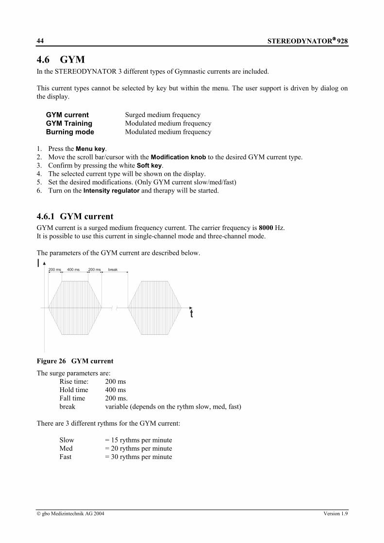
STEREODYNATOR 928
gbo Medizintechnik AG 2004 Version 1.9
44
4.6 GYMIn the STEREODYNATOR 3 different types of Gymnastic currents are included.
This current types cannot be selected by key but within the menu. The user support is driven by dialog onthe display.
GYM current Surged medium frequencyGYM Training Modulated medium frequencyBurning mode Modulated medium frequency
1. Press the Menu key.2. Move the scroll bar/cursor with the Modification knob to the desired GYM current type.3. Confirm by pressing the white Soft key.4. The selected current type will be shown on the display.5. Set the desired modifications. (Only GYM current slow/med/fast)6. Turn on the Intensity regulator and therapy will be started.
4.6.1 GYM currentGYM current is a surged medium frequency current. The carrier frequency is 8000 Hz.It is possible to use this current in single-channel mode and three-channel mode.
The parameters of the GYM current are described below.
I200 ms 200 ms400 ms break
Figure 26 GYM current
The surge parameters are:Rise time: 200 msHold time 400 msFall time 200 ms.break variable (depends on the rythm slow, med, fast)
There are 3 different rythms for the GYM current:
Slow = 15 rythms per minuteMed = 20 rythms per minuteFast = 30 rythms per minute

STEREODYNATOR 928
gbo Medizintechnik AG 2004 Version 1.9
45
4.6.2 GYM Training
The GYM Training current is a modulated medium frequency current in surged mode.The carrier frequency is 8000 Hz.It is possible to use this current in single-channel mode and three-channel mode.The parameters of the GYM Training current are described below.
ms
50 Hz
15 15 155 5
Figure 27 GYM Training current
The surge parameters are:Rise time: 3 sHold time 3 sBreak time 3 s
4.6.3 Burning mode
The Burning mode current is a modulated medium frequency currentThe carrier frequency is 8000 Hz.It is possible to use this current in single-channel mode and three-channel mode.The parameters of the GYM Training current are described below.
ms
3 Hz
300 300 30033 30Figure 28 Burning mode current

STEREODYNATOR 928
gbo Medizintechnik AG 2004 Version 1.9
46
5 GalvanopalpationThe sensitive and vasomotor cutaneous nerves in certain body segments are examined to get indirectconclusions on diseases of inner organs.
1. Connect the electrode handpiece to the socket (1).2. Connect the electrolytically inactive electrode to the red cable.3. The electrolytically inactive electrode will be applied far from the examination place as a cathode
(switch-over of polarity, s.b.).4. Press the Galv key.5. Set the operation mode to CV by pressing the Operation mode key.6. Set the polarity to ”-” by pressing the Polarity key.7. Now the active electrode handpiece is the anode. It serves for palpation.8. Set the intensity (by turning the Intensity regulator) and place the electrode handpiece firmly on the
examination area.9. Turn the Intensity regulator slowly until the stimulus is just noticeable.10. Now the electrode handpiece can be moved over the skin and herewith also removed. With the
movement the stimulating current will alter depending on the patient resistance and the electrodepressure.
11. After the expiration of treatment set the Intensity regulator and Therapy time (as far as it has notautomatically run down) to ”0.0”. If the device remains unused for more than 2 minutes with theintensity adjusted, the patient will be disconnected from the circuit.

STEREODYNATOR 928
gbo Medizintechnik AG 2004 Version 1.9
47
6 Electrokinetic TherapyElectrokinetic therapy is the application of stimulation current with moving electrodes. The application isonly carried out in operation mode CV (= constant voltage).
AttentionMoisten the electrode intermediate layers (dripping wet)!
6.1 Detection of Trigger Points With the Electrode Handpiece
Sometimes it is advisable to detect the appropriate muscular trigger point by moving the electrode handpieceon the skin.
1. Connect the electrode handpiece to the socket (1).2. Connect the electrolytically inactive electrode to the red cable.3. The electrolytically inactive electrode will be placed as a cathode (switch over of polarity, s.b.) away
from the area to be examined.4. Press the desired current type key.5. Set the operation mode on CV by pressing the operation mode key.6. Set the polarity to ”-” by pressing the Polarity key.7. The active electrode handpiece is anode now.8. Set the intensity (by turning the Intensity regulator) and put the electrode handpiece firmly on the area
to be examined.9. Turn the Intensity regulator slowly until stimulation is slightly noticeable.10. Now you can move the electrode handpiece over the skin and you can also remove it. The stimulating
current alters according to the patient resistance and the electrode pressure.11. Set the Intensity regulator and Therapy time (as long as it has not yet expired itself) to ”0.0” after the
expiration of examination. If you do not work with the device for more than 2 minute with the intensityadjusted, the patient will be interrupted from the circuit.
6.2 Stimulation Massage
The stimulation massage will be realized with a moving plate electrode under current conduction.1. Use two plate electrodes in well moistened electrode pockets.2. One electrode will be fixed firmly on the skin.3. The second (active, mobile) electrode will be moved over the skin.4. It is advisable to put on rubber gloves in order not to get electrified yourself when you touch the active
electrode.5. Press the desired current type key.6. Set the operation mode to CV by pressing the Operation mode key.7. Put the mobile electrode firmly on the skin.8. Turn the Intensity regulator slowly until the desired stimulation has been achieved.9. Move the mobile electrode over the skin. There is no adverse effect if you take off the electrode.
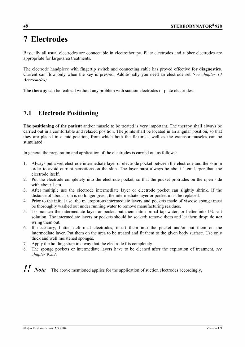
STEREODYNATOR 928
gbo Medizintechnik AG 2004 Version 1.9
48
7 ElectrodesBasically all usual electrodes are connectable in electrotherapy. Plate electrodes and rubber electrodes areappropriate for large-area treatments.
The electrode handpiece with fingertip switch and connecting cable has proved effective for diagnostics.Current can flow only when the key is pressed. Additionally you need an electrode set (see chapter 13Accessories).
The therapy can be realized without any problem with suction electrodes or plate electrodes.
7.1 Electrode Positioning
The positioning of the patient and/or muscle to be treated is very important. The therapy shall always becarried out in a comfortable and relaxed position. The joints shall be located in an angular position, so thatthey are placed in a mid-position, from which both the flexor as well as the extensor muscles can bestimulated.
In general the preparation and application of the electrodes is carried out as follows:
1. Always put a wet electrode intermediate layer or electrode pocket between the electrode and the skin inorder to avoid current sensations on the skin. The layer must always be about 1 cm larger than theelectrode itself.
2. Put the electrode completely into the electrode pocket, so that the pocket protrudes on the open sidewith about 1 cm.
3. After multiple use the electrode intermediate layer or electrode pocket can slightly shrink. If thedistance of about 1 cm is no longer given, the intermediate layer or pocket must be replaced.
4. Prior to the initial use, the macroporous intermediate layers and pockets made of viscose sponge mustbe thoroughly washed out under running water to remove manufacturing residues.
5. To moisten the intermediate layer or pocket put them into normal tap water, or better into 1% saltsolution. The intermediate layers or pockets should be soaked; remove them and let them drop; do notwring them out.
6. If necessary, flatten deformed electrodes, insert them into the pocket and/or put them on theintermediate layer. Put them on the area to be treated and fit them to the given body surface. Use onlythick and well moistened sponges.
7. Apply the holding strap in a way that the electrode fits completely.8. The sponge pockets or intermediate layers have to be cleaned after the expiration of treatment, see
chapter 9.2.2.
!! Note The above mentioned applies for the application of suction electrodes accordingly.
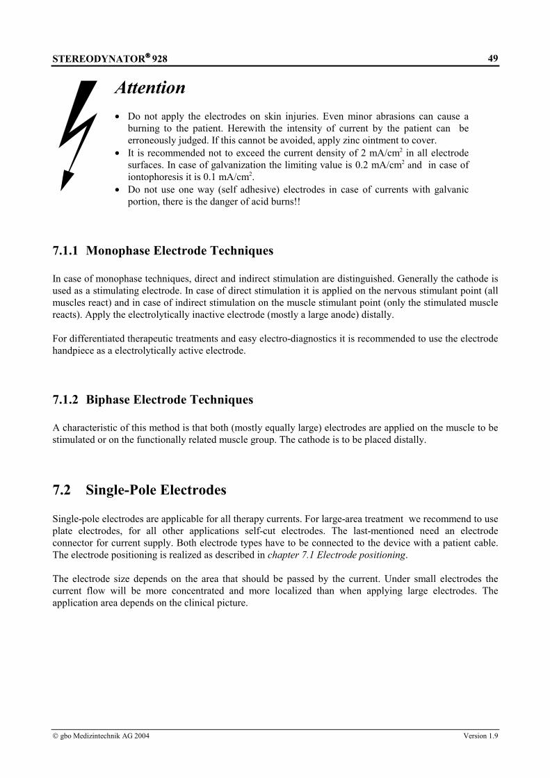
STEREODYNATOR 928
gbo Medizintechnik AG 2004 Version 1.9
49
Attention• Do not apply the electrodes on skin injuries. Even minor abrasions can cause a
burning to the patient. Herewith the intensity of current by the patient can beerroneously judged. If this cannot be avoided, apply zinc ointment to cover.
• It is recommended not to exceed the current density of 2 mA/cm2 in all electrodesurfaces. In case of galvanization the limiting value is 0.2 mA/cm2 and in case ofiontophoresis it is 0.1 mA/cm2.
• Do not use one way (self adhesive) electrodes in case of currents with galvanicportion, there is the danger of acid burns!!
7.1.1 Monophase Electrode Techniques
In case of monophase techniques, direct and indirect stimulation are distinguished. Generally the cathode isused as a stimulating electrode. In case of direct stimulation it is applied on the nervous stimulant point (allmuscles react) and in case of indirect stimulation on the muscle stimulant point (only the stimulated musclereacts). Apply the electrolytically inactive electrode (mostly a large anode) distally.
For differentiated therapeutic treatments and easy electro-diagnostics it is recommended to use the electrodehandpiece as a electrolytically active electrode.
7.1.2 Biphase Electrode Techniques
A characteristic of this method is that both (mostly equally large) electrodes are applied on the muscle to bestimulated or on the functionally related muscle group. The cathode is to be placed distally.
7.2 Single-Pole Electrodes
Single-pole electrodes are applicable for all therapy currents. For large-area treatment we recommend to useplate electrodes, for all other applications self-cut electrodes. The last-mentioned need an electrodeconnector for current supply. Both electrode types have to be connected to the device with a patient cable.The electrode positioning is realized as described in chapter 7.1 Electrode positioning.
The electrode size depends on the area that should be passed by the current. Under small electrodes thecurrent flow will be more concentrated and more localized than when applying large electrodes. Theapplication area depends on the clinical picture.

STEREODYNATOR 928
gbo Medizintechnik AG 2004 Version 1.9
50
AttentionFor current types for which there exists the threat of cauterization (currents withgalvanic portion), the maximum recommended current density is 0.5 mA/cm2
electrode surface. In case of galvanization the limit value is 0.2 mA/cm2 and in caseof iontophoresis 0.1 mA/cm2.
Electrode Surface Max. Current / Galv / IontophoresisConductive rubber electrode 3 cm x 4 cm 12 cm2 24 mA / 2.4 mA / 1.2 mAConductive rubber electrode 6 cm x 8 cm 48 cm2 96 mA / 9.6 mA / 4.8 mAConductive rubber electrode 8 cm x 12 cm 96 cm2 192 mA / 19.2 mA / 9.6 mAPlate electrode 9 cm x 12 cm 108 cm2 216 mA / 21.6 mA / 10.8 mA
Table 1: Maximum Current of conductive rubber electrodes and plate electrode

STEREODYNATOR 928
gbo Medizintechnik AG 2004 Version 1.9
51
7.3 Three-pole electrodes
7.4 Suction Electrodes
The triple-pole electrodes can be used forstereodynamic interference currents.
The conductive rubber electrodes of the threecircuits are placed in two flexible three-polestar electrode sets (I and II) and attached to acommon patient cable. There are three sizesavailable (small, standard and large). Electrodepockets are necessary for the application andfixing material for the bandage (seeaccessories).
Each stereodynamic electrode set is placed intoa well wetted pocket so that the blackconductive rubber electrodes face the humiditycarrier. The reverse side of the pocket consistsof transparent synthetic material in order to beable to check the correct positioning of theelectrode.
Electrode position:
A) If the electrodes are placed opposite to eachother (transverse current flow,transregional) the cable connections mustpoint in opposite directions.
B) If the electrodes are placed on one side(longitudinal current flow), their cablesmust point in the same direction.
Only in the case of these electrode positions theflow paths of current of the three circuits cantranspose and optimal stereodynamicstimulation currents are generated.
In special cases (e.g. depending on theapplication in the case of shoulder-handsyndrome) it is possible to deviate from thisgeneral rule.
You can also use triple-pole suction electrodes,if your device is equipped with a suctionapplication aid. The above mentioned alsoapplies to the application with suctionelectrodes.
A)
B)

STEREODYNATOR 928
gbo Medizintechnik AG 2004 Version 1.9
52
7.4 Suction Electrodes
Instead of the above-mentioned electrodes, suction electrodes can be used for faster application. The devicetechnics necessary for this is described in chapter 3.2 Integrated Suction Application Aid .
Achtung• For current types for which there exists the threat of cauterization (currents with
galvanic portion), the maximum recommended current density is 0.5 mA/cm2
electrode surface. In case of galvanization the limit value is 0.2 mA/cm2.• In case of iontophoresis don’t use suction electrodes.
Suction electrode Surface Max. current value / GalvElectrode plate small 6 cm2 12 mA / 1.2 mAElectrode plate standard 12 cm2 24 mA / 2.4 mAElectrode plate large 28 cm2 56 mA / 6 mA
Table 2: Maximum current of the suction electrodes
7.5 Electrode Handpiece
The electrode handpiece is applicable for small, local treatments and simple electro-diagnostics (see alsochapter 7.1.1 Monophase Electrode Tcs). The electrode handpiece (electrolytically active electrode) isfirmly connected to the patient cable. With a second wire the plate electrode is connected (electrolyticallyinactive electrode). In addition an electrode set is necessary, which consists of metal shaft, electrode pocketsand rubber rings (see chapter 13 Accessories).
The following procedure is advisable:
1. Connect the electrode handpiece.2. The electrode handpiece will be recognized by the device.
!! NoteThe fingertip is without any function in the therapy mode. The selected current is issuedindependently from the switch position!

STEREODYNATOR 928
gbo Medizintechnik AG 2004 Version 1.9
53
8 TroubleshootingThe following exceptions are signaled by the current stimulation device optically via the display andacoustically. Most of the exceptions can be cleared by following the displayed instructions.
In general an exception is characterized by the following sequence of events:1. The device does not react on a command, given by a key or by turning a regulator.1. A warning signal is sounded.2. An error message is displayed.3. If the user does not react according to the displayed messages, the most recent faultless device condition
is restored after a time-out. Global Error Conditions
Error messages:♦ Error in the 386 EX-module !♦ Error: DSP is not responding !♦ Error while booting the DSP♦ Error while writing to the DSP !♦ Task Timeout !♦ Overheating !♦ Defect of the power amplifier !♦ Turn off unit and call service !
Suggestions:Turn off and turn on unit. A full selftest of all device functions is performed and the unit is reinitialized. Ifthe unit does not come up in normal state please call your local service.
Application Errors
Error message:♦ Wrong electrode !
Suggestion:You have connected an unsuitable electrode. Please use a suitable electrode for the current type of yourchoice (see chapter 7 Electrodes).
Error Messages:♦ Check placement of electrodes !♦ Patient cables are shortcircuited !
Suggestion:The current loop to the patient is cut off. Please check electrodes, cables and connectors.

STEREODYNATOR 928
gbo Medizintechnik AG 2004 Version 1.9
54
9 MaintenanceFunctionality, reliability, and safety characteristics of the current stimulation device are only guaranteed incase of proper use in accordance with the operating instructions. Safety control, maintenance work, repairwork, and modifications shall be carried out only by the manufacturer or by service agents authorized byhim. In case of a failure, parts which influence the safety of the device shall be only replaced by originalspare parts of the manufacturer. The electric installation must correspond to the requirements in accordancewith VDE/IEC. The device does not contain any parts which need maintenance work done by the user.
9.1 Safety ControlsThe device is subject to the provisions of the Medical Device Directive. The safety controls have to becarried out on the basis of this directive. Thereby, the operator regulation has to be especially observed.
Irrespective of the legal rules or beyond the scope of the Medical Device Directive, it is recommended tohave the device checked by the manufacturer or by a service agency authorized by him at 12- monthsintervals.
The check shall consist of at least the following criteria:• Electrical safety check in accordance with the test plan of the manufacturer,• Check of the device in respect of external integrity,• Check of all display and operating elements in respect of damages,• Check of all inscriptions in respect of legibility.
9.2 Cleaning, Disinfection and Care
9.2.1 Current Stimulation DeviceFor cleaning and disinfection of the current stimulation device and its accessories (except electrode fleece,electrode pockets or felts, see chapter 9.2.2) there should not be used any agents containing higher portionsof phenol derivatives, alcohol, compounds of chlorine or peracetic acid. It is recommended to usedisinfectants on aldehyde basis.
The device is not suited for heat sterilization or for sterilization with gases.
AttentionBefore cleaning or disinfection unplug the mains plug out of the socket!
The current stimulation device is suited for wiping disinfection. It has to be observed that no liquids enterthe device. In no case shall the plug or socket get wet. For cleaning or disinfection the device may not bedrizzled.
9.2.2 Electrode Fleece, Electrode Pockets or Felts
1. Put the material into neutral soap-suds and rub it slightly. If necessary, disinfect with disinfectantsolution, but do not put it into it.
2. Leave the parts over the night in the neutral soap-suds or tap water.3. Take them out, and wash them several times thoroughly out under cold or warm running water.4. Let them drop, but do not wring them out.

STEREODYNATOR 928
gbo Medizintechnik AG 2004 Version 1.9
55
10 Warnings and Safety Precautions
Attention !• In case of patients with implanted electronic device carry out electrical stimulation
treatment only after having checked whether there is any risk. • Pieces of jewellery and glasses have to be taken off during the treatment.
• Turn off cellular phones and radiophone or place them in a distance of 3 m from thedevice.
• Cardiac pacemakers can extremely be disturbed. In these cases the therapy should beonly carried out under continuous pulse and ECG control.
• If the patient and/or the patient cable is in direct range of a high-frequency, short-
wave or micro-wave therapeutic device, a damage to the device or an injury of thepatient cannot be excluded. Please keep a distance of 3 m.
• A simultaneous connection of the patient to a high-frequency surgery device can
lead to burns under the electrical stimulus electrodes. • It is recommended not to exceed the current density of 2 mA/cm2 on all electrode
surfaces. • For current types for which there exists the threat of cauterization (currents with
galvanic portion), the maximum recommended current density is 0.5 mA/cm2
electrode surface. In case of galvanization the limit value is 0.2 mA/cm2 and in caseof iontophoresis 0.1 mA/cm2.
• Do not use one way (self adhesive) electrodes with currents with galvanic portion,
there is the threat of cauterization!! • The unit is not designed to be operated in places with the inherent risk of
explosions. If it is used in dangerous areas of anesthesia departments, the possibilityof an explosion cannot be excluded.
• In case of all visible failures contact immediately gbo Medizintechnik AG or one of
the service agencies authorized by gbo Medizintechnik AG .

STEREODYNATOR 928
gbo Medizintechnik AG 2004 Version 1.9
56
Contraindications for use of ultrasound
Ultrasonic therapy must not be used in the following instances:• Patients with a fever• Infectious diseases, dermatological conditions• Blood coagulation problems• Pregnancy• Tuberculosis, stomach ulcers• Peripheral vascular disease• Tumors, circulatory instability and coronary diseases• Acute rheumatoid arthritis• Diabetes mellitus• Septic inflammation• Following recent thorium-X treatment or x-ray depth treatment
The following organs must not be treated directly:• Eyes• Medulla• Laminectomy-related spinal incisions• Heart, lungs• Anesthetized areas

STEREODYNATOR 928
gbo Medizintechnik AG 2004 Version 1.9
57
11 Explanation of the Signs Used
0123 CE – conformity sign
Attention !Observe the instructions for use !
Application part ungrounded, protection degree Type BF
Ultrasound probe connection
Patient cable connection
Suction electrode I connection
Suction electrode II connection
This product complies with WEEE Directive 2002/96/EG(waste electrical and electronic equipment). Separatecollection for electrical and electronic equipment.

STEREODYNATOR 928
gbo Medizintechnik AG 2004 Version 1.9
58
12 Technical DataMains voltage and frequency: 100, 120, 230, 240 V, 48-62 HzCurrent consumption*: 120 V: max. 3.3 A 230 V: max. 1.65 AMains fuse*: 120 V: T3.2 A 230 V: T1.6 AOutput current: max. 200 mAOutput voltage: max. 200 VMDD device class IIbProtection against ingress of liquids IP X1Protection class: I in accordance to IEC 601 / VDE 0750Protection degree: BF in accordance to IEC 601Dimensions*: max. 15 cm x 41 cm x 48 cm (H x D x W)Weight*: max. 17 kg without accessoriesColor: white RAL 9002Display: LCD backlighted, 320 X 240 dots full graphicBattery: CR 2032environmental conditions: operation of the
device:temperature range +10 °C ... +40 °Crelative humidity of air 30 ... 75 %
transport andstorage:
temperature range +5 °C ... +50 °Crelative humidity of air < 90 %, non condensing
Current types: Galv - Galvanic currentSMS - Strong muscle stimulation according to EichhornDF/CP - Diadynamic currentsUR - Ultra stimulation currentMicro - micro-stimulus currentF1 - Faradic currentHV - high voltageT/R - Universal-TherapyTENS - Transcutaneous electrical nerve stimulationTENS Burst - Trans. electr. nerve stimulation in impulse groupsMF I – VII - Middle-frequency currentsIG 30/50 - Impulse galvanizationFM - Frequency modulationLP/MF - Diadynamic currentsIncontinence - Rectangular current incontinenceSedat - Interference current 200 HzMyomot - Interference current 50 HzVegetat. Stim. I - Interference current 2.5 - 25 HzVegetat. Stim. - Interference current 10 HzVegetat. Stim. - Interference current 0.1 - 1 HzUniversal - Interference current 1 - 200 HzSedat.Mod. - Interference current 100 - 200 HzGYM current surged MF current in single and three channel modeGYM Training modulated MF current in single and three channel modeBurning mode modulated MF current in single and three channel mode
Therap.ultrasound module: Continuous and pulse mode 1:5, 1:10, 1:20Ultrasound frequency: 1/3 MHzUltrasound power: max. 3 W per 1 cm2 radiating surface at 1 MHz
max. 1,5 W per 1 cm2 radiating surface at 3 MHzUltrasound probe: 2,5 cm2 and 5 cm2 radiating surfaceSuction application module:Suction: At least 150 mbar in maximum positionSuction massage frequency: 0 - 60 pulses per minute*) dependent on the device type and/or whether the device is equipped with therapeutic ultrasound modules andsuction application modules.
gbo Medizintechnik AG reserves the right to modify the design and specification without prior notice.

STEREODYNATOR 928
gbo Medizintechnik AG 2004 Version 1.9
59
Current Grafics Pulseduration T in
ms
PausedurationR in ms
D.C.portion
in %
Frequencyin Hz
Maximum outputvoltage by CV in
Vpeak
Max. outputcurrent by CC in
mApeak
Galvanic current- - 100 0 70 701)
Ultrastimulationcurrent
2.0 5.0 28.6 143 70 70
Faradic current1.0 - 3.0 17.0 - 19.0 2.6 50 70 70
Strong musclestimulation
0.02 - 2000 0.5 ms - 10s
0 0.1 - 2000 70 70
Micro-stimuluscurrent
0.02 - 40 0.5 ms - 10s
0 20 - 2000 5 5
Universal therapy0.02 - 2000 0.5 ms - 10
s0.1 - 2000 70 70
Diphasé fixe- - 63 100 70 70
Courtes périodes- - 47.25 50 / 100 70 70
Middle frequencycurrent 8 kHz
MF I / surged- - 0 - 140 140
MF II / sinus surged- - 0 - 140 140
MF III / 50 Hz4.0 0.5 ms - 10
s0 0.1 –
222.2140 140
MF IV / 3 - 10 Hz50 - 167 50 - 167 0 3.0 - 10 140 140
MF V / 10 - 30 Hz16.5 – 50.0 16.5 – 50. 0 0 10 - 30 140 140
MF VI /30 - 60 Hz
8.3 – 16. 0 8.3 – 16.0 0 30 - 60 140 140
MF VII /100 - 200 Hz
4.0 1.0 – 6.0 0 100 - 200 140 140
High voltagecurrents
HV I / 50 Hz4.5 0.5 ms - 10
s0 0.1 - 200 200 200
HV II / 3 -10 Hz4.5 95.5 –
325.50 3.0 - 10 200 200
HV III /10 - 30 Hz
4.5 28.5 – 95.5 0 10 - 30 200 200
HV IV /30 - 60 Hz
4.5 12.5 – 28.5 0 30 - 60 200 200
HV V /100 - 200 Hz
4.5 0.5 – 5.5 0 100 - 200 200 200
Tens currents
Tens I / 100 Hz0.2 0.5 ms – 10
s0 0.1 -
1428.6100 100
Tens II / 3 - 10 Hz
0.2 100.0 -330.0
0 3.0 - 10 100 100
1) In case of using the suction electrodes the maximum current is reduced to 20 mA.

STEREODYNATOR 928
gbo Medizintechnik AG 2004 Version 1.9
60
Current Grafics Pulseduration T in
ms
PausedurationR in ms
D.C.portion
in %
Frequencyin Hz
Maximum outputvoltage by CV in
Vpeak
Max. outputcurrent by CC in
mApeakTens III /10 - 30 Hz
0.2 33.0 - 100.0 0 10 - 30 100 100
Tens IV /30 - 60 Hz
0.2 17.0 - 33.0 0 30 - 60 100 100
Tens V /100 - 200 Hz
0.2 5.0 - 10.0 0 100 - 200 100 100
Tens BurstcurrentsTens Burst I /50 Hz
2.0 0.5 ms – 10s
0 0.1 - 400 100 100
Tens Burst II /3 - 10 Hz
2.0 98.0 - 328.0 0 3.0 - 10 100 100
Tens Burst III /10 - 30 Hz
2.0 31.0 – 98.0 0 10 - 30 100 100
Tens Burst IV /30 - 60 Hz
2.0 15.0 – 31.0 0 30 - 60 100 100
Tens Burst V /100 - 200 Hz
2.0 3.0 – 8.0 0 100 - 200 100 100
Special currents
Monophasé fixe MF 10 10 31.5 50 70 70
Longues périodes LP - - 46 50 / 100 70 70
ImpulsegalvanizationIG 30
30.0 50.0 18 12.5 70 70
ImpulsegalvanizationIG 50 / surged
50.0 70.0 0.3 8.3 70 70
FrequencymodulationFM / 7 - 14 Hz
0.5 70.9 –142.4
0.4 7 - 14 70 70
Incontinence0.02 - 100 0.5 - 100 0 10 - 90 70 70
Interferencecurrents2)Sedat200 Hz
- - 0 200 140 -
Myomot50 Hz
- - 0 50 140 -
Vegetat. Stim I2.5 - 25 Hz
- - 0 2.5 - 25 140 -
Vegetat. Stim II10 Hz
- - 0 10 140 -
Vegetat. Stim III0.1 - 1 Hz
- - 0 0.1 - 1 140 -
Universal1 - 200 Hz
- - 0 1 - 200 140 -
Sedat.Modulation100 - 200 Hz
- - 0 100 - 200 140 -
2) The output current is reduced to 100 mA.

STEREODYNATOR 928
gbo Medizintechnik AG 2004 Version 1.9
61
13 AccessoriesArticle Article numberSTEREODYNATOR® 928 014-0-928STEREODYNATOR® 928
inclusive ultrasonic therapy module, inclusive 1 ultrasonic transducer 5 cm2,inclusive 1 contact gel 250 ml
014-0-928-U
STEREODYNATOR® 928 inclusive suction application aid 014-0-928-VSTEREODYNATOR® 928 inclusive ultrasonic therapy module, inclusive 1 ultrasonic transducer 5 cm2,
inclusive 1 contact gel 250 ml and inclusive suction application aid
014-0-928-UV
Adapter connector, drill hole and pin diameter 4 mm, in case of use with olderaccessories with new cable to the patient 45-38-245EH725
Bow electrode 011-0-0024Conductive rubber electrode with cable 3 cm x 4 cm (fleece pockets small) 45-38-880EH725Conductive rubber electrode with cable 6 cm x 8 cm (fleece pockets medium) 45-38-898EH725Conductive rubber electrode with cable 8 cm x 12 cm (fleece pockets 45-38-
203EH725 or viscose sponge pockets 22-73-621Q1408) 45-38-492EH725Contact gel Lectro-Sonic, 250 ml 45-39-128EH725Device cart UNICAR® 900 014-0-0008Diagnostic set (patient cable, sheet tins with cutting template, intermediate fleece
layers, electrode connector, connecting terminals, rubber straps, fixing buttons)45-39-177EH725
Diagnosis sheet, I/T curves (100 pieces) 71-21-635E2200Diagnosis sheet, trigger points trunk (100 pieces) 71-21-643E2200Diagnosis sheet, upper extremities (100 pieces) 71-21-650E2200Diagnosis sheet, lower extremities (100 pieces) 71-21-668E2200Elastic tape with closure (velcro), 70 cm long , 7.5 cm wide (2 pieces) 45-38-997EH725Electrode handpiece with finger tip switch 45-38-401EH725Electrode set for electrode handpiece 45-38-450EH725Electrode pockets, small, (10 pcs.) for star electrode small 49-07-317E3020Electrode pockets, standard, (10 pcs.) for star electrode standard 49-07-309E3020Electrode pockets, large, (10 pcs.) for star electrode large 49-07-325E3020Electrode intermediate layers small, diameter 36 mm (12 pieces) for suction
electrodes, small 45-38-518EH722 45-38-922EH722Electrode intermediate layers standard, diameter 52 mm (12 pieces) for suction
electrode set, standard 45-38-500EH722 45-38-930EH722Electrode intermediate layers large, diameter 72 mm (12 pieces) for suction
electrodes, large 45-38-526EH722 45-38-948EH722Sponge pockets, large (10 pieces) for plate electrodes 45-38-468EH725 and
conductive rubber electrodes 45-38-492EH725 45-38-203EH725Sponge pockets, large (10 pieces) for plate electrodes 45-38-468EH725 and
conductive rubber electrodes 45-38-492EH725 45-38-203EH725Sponge pockets, small (10 pieces) for conductive rubber electrodes small 45-39-102EH725Sponge pockets, medium (10 pieces) for conductive rubber electrodes medium 45-39-110EH725Electrode pockets, large, (10 pcs.) for star electrode large 49-07-325E3020

STEREODYNATOR 928
gbo Medizintechnik AG 2004 Version 1.9
62
Article Article numberIntermediate layer made of viscose sponge, 30 cm x 20 cm x 1 cm (5 pieces) 45-38-476EH725Intermediate layer made of fleece, 32 cm x 22 cm (5 pieces) 45-38-211EH725Paper sheets for suction electrodes 45-38-856EH722 and 45-38-864EH722 71-21-841EH060Patient cable, double-wire, 2.5 m long 45-38-435EH725Plate electrode with cable, 9 cm x 12 cm 45-38-468EH725Rectal electrode 014-0-0007Sheet tin, 18 cm x 28 cm (3 pieces) for making plate electrodes (use it with electrode
connector 45-38-237EH725 and connecting terminal 45-02-076EH023) 45-38-229EH725Sheet tin plate electrode 9 cm x 12 cm with fix cable and socket 4 mm 45-38-468EH725Suction electrode I with cable 45-38-534EH722Suction electrode II with cable 45-38-542EH722Suction electrode, single-pole, small, diameter 34 mm 45-38-518EH722Suction electrode, single-pole, large, diameter 70 mm 45-38-526EH722Suction electrode set, single-pole, standard, diameter 50 mm 45-38-500EH722Suction cub small, diameter 34 mm 45-38-567EH722Suction cub standard, diameter 50 mm 45-38-575EH722Suction cub large, diameter 70 mm 45-38-583EH722Stereo suction electrode set (Stereo suction electrode pair, paper sheets) 45-38-856EH722Star electrode pair, small (diameter 80 mm) 45-38-708EH725Star electrode pair, standard (diameter 130 mm) 45-38-716EH725Star electrode pair, large (diameter 180 mm) 45-38-724EH725Stern electrode set Standard (star electrodes 3-pole, electrode pockets, rubber tapes) 45-38-260EH719Therapy set 1 (patient cable, sheet tin electrodes, intermediate fleece layers, rubber
tapes, fixing buttons)45-39-151EH725
Therapy set 2 (cable to the patient, conductive rubber electrodes, fleece pockets,elastic tapes with closure (velcro)
45-39-169EH725
3-channel therapy-set (complete) 014-0-0011Ultrasound probe with cable and plug, ultrasound surface 5 cm2 023-0-0141Ultrasound probe with cable and plug, ultrasound surface 2,5 cm2 023-0-0140Vaginal electrode 014-0-0006Viscose sponge pockets (10 pieces) 22-73-621Q1408
UNICAR® 1000 device cart (basic rack) anddevice porter (large)
014-0-1000 and014-0-1020
UNICAR® 1000E device cart (basic rack with electric distribution and switch) anddevice porter (large)
014-0-1000E and014-0-1020
STEREODYNATOR 928
gbo Medizintechnik AG 2004 Version 1.9
63
IndexA
acoustic user support 13alarm beep 19Application errors 51assembly 15attention 15, 27, 32, 47, 48, 52, 53Automatic programs 31
Bbiphase current 20biphase electrode technics 47
Ccare 52CC mode 20connection 15current value 19
Ddiadynamic currents 33, 40disinfection 52display 18duration time 21
Eelectrode handpiece 50elektrode fleece 52elektrode positioning 46error messages 51exceptions 51
Ffaradic current 37FM 40frequency lock 21frequency modulation 40
Ggalvanic base 21galvanic current 19, 36
Hhigh-voltage currents 35
Iimpuls galvanization 40incontinence 40intensity regulator 19inverse representation 18iontophoresis 36
LLED 13, 18longitudinal current flow 49
Mmaintenance 52menu 24menu application with electrotherapy 32Menu Programs 31menu special current types 39MF 40micro-stimulus current 39middle frequency currents 34Monophase current 20monophase electrode technics 47monophasé Fixe 40Myomot 30
Ooperation mode 20, 45optical user support 13
Ppause duration 18, 22pause time 21polarity 19pole change 20pulse duration 18, 22pulse rise 22
Rrise time 21
Ssafety controls 52Sedat 29Sedation Modulation 30settings 16short instruction 12single-pole electrodes 47soft key 24Star display 18strong muscle stimulation 34suction application unit 26suction electrodes 26, 50surge parameters 21switching on 16
TTENS 37TENS Burst 38therapy time 22Three pole electrodes 49transcutaneous electrical nerve stimulation 37

STEREODYNATOR 928
gbo Medizintechnik AG 2003, Medical Devices Division Version 1.9
64
transport 15transverse current flow 49troubleshooting 51
Uultrasound module 27ultrasound/current-combination 27ultrastimulation current 35Universal 30universal-therapy 39unsuitable electrode 51
VVegetat. Stim. I 30Vegetat. Stim. II 30Vegetat. Stim. III 30Voltage Selection 15
Wwarning signal 19, 51warnings 15, 53wrong electrode 51

STEREODYNATOR 928 65
gbo Medizintechnik AG 2004 Version 1.9
Number Current typeCV/CC
Basisautom T R / + / -
Remarks
Storing of Therapeutic Current Types

STEREODYNATOR 928 66
gbo Medizintechnik AG 2004 Version 1.9
Correction sheet
gbo Medizintechnik AG- Dokumentation -Kleiststraße 6
64668 Rimbach
Please work on the faults and/or suggestions to the present documentation:
Page Line faulty text right text
(If needed, please attach an additional sheet)
Address:
Part-No. 014-7-0019