Langzeitarchivierung und Metadaten. NAA Preservation Strategy Link: ml.
Ingenieurfakultät Bau Geo Umwelt
Lehrstuhl für Computergestützte Modellierung und Simulation
Consistency preservation methods for multi-scale design of subway infrastructure facilities
Javier Ramos Jubierre
Vollständiger Abdruck der von der Ingenieurfakultät Bau Geo Umwelt der Technischen
Universität München zur Erlangung des akademischen Grades eines
Doktor-Ingenieurs
genehmigten Dissertation.
Vorsitzende(r): Univ.-Prof. Dr.rer.nat. Ernst Rank
Prüfer der Dissertation: 1. Univ.-Prof. Dr.-Ing. André Borrmann
2. Prof. Dr.-Ing. Christian Koch
The University of Nottingham
Die Dissertation wurde am 24.10.2016 bei der Technischen Universität München eingereicht
und durch die Ingenieurfakultät für Bau Geo Umwelt am 30.01.2017 angenommen.

i
Abstract
The design of large infrastructure facilities, such as inner-city subway lines, requires the consideration
of widely divergent scales. This ranges from the kilometer scale, for the basic alignment definition,
down to the centimeter scale, for the design of underground stations and hubs. Moreover, the strongly
inter-disciplinary nature of infrastructure projects implies an intensive exchange of highly semantic
design information between the different engineering teams participating in the project. Though the
exchange of this information is successfully accomplished by current product models, none of them
are able to guarantee the specific consistency demands required during the multi-scale design of large
infrastructure facilities.
To close this technological gap, this thesis focuses on two main aspects of the exchange of design
information. First, a comprehensive multi-scale shield tunnel product model is presented, which makes
extensive use of a spatial structure concept. The resulting hierarchical structure of entities matches the
demands of conceptual and detailing design stages, placing the physical objects only after their space
definition is known. Moreover, the previously defined spaces are assigned to different scales or levels
of detail (LoD). Secondly, in order to guarantee the geometric consistency across the different LoDs,
this thesis introduces a novel geometric representation based on parametric techniques. To this end,
procedural geometric representations are introduced during the definition of coarse LoDs, giving to the
design process a high level of flexibility. For the detailed design on LoD5, a dual design approach
combining procedural and assembly models is introduced. Thus, the introduction of assembly models
enables the construction of a hierarchical structure of assemblies and parts that reproduce the seman-
tic description of the product model, and improves its overall performance. Finally, as an evaluation
and proof-of-concept, these methods are implemented and successfully applied in a real case study
based on the Second main suburban track, which is about to be constructed in the city of Munich,
Germany.


iii
Zusammenfassung
Der Entwurf großer Infrastrukturbauwerke erfordert den Einsatz sehr unterschiedlicher Skalen. Bei der
Planung von U-Bahnlinien arbeitet man im Kilometerbereich bei der Definition der zugrunde liegenden
Trassierung und gelangt in den Zentimeterbereich bei der detaillierten Ausgestaltung der einzelnen U-
Bahnstationen und Knotenpunkte. Der hohe Grad an Interdisziplinarität bei Infrastrukturbauprojekten
erfordert den intensiven Austausch hochwertiger semantischer Planungsinformationen zwischen den
teilnehmenden Ingenieurteams. Der erfolgreiche Austausch dieser Informationen wird von gängigen
Produktmodellen gewährleistet. Nichtsdestotrotz können diese aber nicht die spezifischen Anforde-
rungen hinsichtlich der Konsistenz garantieren, wie sie von mehrskaligen Infrastrukturmodellen gefor-
dert werden.
Um diese technologische Lücke zu schließen, konzentriert sich diese Arbeit auf zwei wesentliche
Aspekte beim Austausch von Planungsinformationen: Zuerst wird ein allgemeingültiges mehrskaliges
Produktmodell für Schildtunnel präsentiert, das einen ausgiebigen Gebrauch von einem räumlichen
Strukturkonzept macht. Die sich hieraus ergebende hierarchische Struktur von Entitäten erfüllt die
Anforderungen, die während den konzeptionellen und detaillierten Entwurfsphasen auftreten, indem
die realen physikalischen Objekte erst dann platziert werden, wenn ihre räumlich Lage genau spezifi-
ziert wurde. Zudem werden die zuvor festgelegten Räume verschiedenen Skalen oder Detailierungs-
ebene (Levels of Detail – LoD) zugeordnet. In einem zweiten Schwerpunkt dieser Arbeit wird eine
neue geometrische Modellierungsmethodik präsentiert, die auf parametrischen Techniken basiert und
die geometrische Konsistenz über verschiedene LoDs hinweg aufrechterhält. Hierzu werden während
der Definition der groben LoDs prozedurale geometrische Darstellungsformen eingeführt, die dem
Entwurfsprozess einen hohen Grad an Flexibilität verleihen. Zusätzlich wird während des detaillierten
Entwurfs in LoD5 ein „zweigleisiger― Entwurfsprozess vorgeschlagen, der prozedurale Modelle und
Baugruppe-Modelle kombiniert. Auf diese Weise erlaubt die Einführung von Baugruppe-Modellen die
Konstruktion einer hierarchischen Struktur, die sowohl Baugruppen als auch Teile enthält, die seman-
tische Beschreibung des Produktmodells einbezieht und zudem die Gesamtperformanz erhöht. Um
die Praxistauglichkeit des präsentierten Ansatzes zu plausibilisieren, wurden diese Methoden ab-
schließend implementiert und in einer Fallstudie angewandt: Diese basiert auf der 2.S-Bahn-Stamm
strecke, die in der bayerischen Landeshauptstadt München gebaut werden soll.


v
Acknowledgements
This thesis is the result of my research at the Chair of Computational Modeling and Simulation, Faculty
of Civil, Geo and Environmental Engineering at Technische Universität München from November 2011
to October 2015.
At this point I want to express my gratitude to my first advisor Prof. Dr.-Ing. André Borrmann. Thanks
for giving me the chance of working in such an innovative and challenging research topic. Your wise
guidance and critical reviews during the writing of this thesis make possible that I finished a work that
at the beginning sounds unattainable to me.
I am also deeply grateful to Prof. Dr.-Ing. Christian Koch, my second supervisor, for his willingness to
act as independent examiner of my work. You have been always a satellite spinning around my topic,
never losing the perspective. Thanks. My sincere gratitude also goes to Prof. Dr.rer.nat Ernst Rank for
being my mentor at the TUM Graduate School and chairman on my examination.
I want also to thank all my former colleagues at the two chairs for making me feel at home. Specially, I
want to thank my former roommates Dr.rer.nat. Yang Ji, Julian Amann, Dominic Singer, and project
successor Simon Vilgertshofer. I wish you all the best success on your respectively research projects.
I will be forever thankful to my project-, room-, and table-mate, my good friend Dr.-Ing. Matthias Flurl.
Thanks for all the good and stressed moments we spend together, for your language corrections, and
your musical soundtrack. You were always a source of inspiration.
Lastly, I want to thank my family, specially my wife Dr. Liya Babenko for her understanding and advice
at the time of writing this thesis. She knew, better than nobody, how hard and lonely could be this task
sometimes.
No puedo terminar estos agradecimientos sin espresar el mas profundo respeto y amor por unos
padres que con su ejemplo me han enseñado a ser la persona que soy hoy. La distancia nunca
evitará que piense en vosotros cada dia, ni que os eche un poco mas de menos. Mis últimas palabras
de agradecimiento no pueden ser para otra que para mi adorable Света. Jamás vi en una persona
tantas ganas de vivir, tanto afán de superación, o tanto optimismo por la vida. Mi ejemplo. Mi vida. Mi
niña.


vii
Contents
Abstract ........................................................................................................................................ i
Zusammenfassung ........................................................................................................................... iii
Acknowledgements ........................................................................................................................... v
Contents ..................................................................................................................................... vii
Introduction .................................................................................................................. 1 Chapter 1.
1.1. Motivation .............................................................................................................................. 1
1.2. Current state on infrastructure design ................................................................................... 2
1.3. Research questions and expected contributions .................................................................. 3
1.4. Thesis overview ..................................................................................................................... 4
State of the art in multi-scale infrastructure design ................................................. 7 Chapter 2.
2.1. Overview ................................................................................................................................ 7
2.2. Multi-scale representations in cartography and geography .................................................. 7
2.2.1. Scale-based cartographic representations .................................................................... 7
2.2.2. Geographic Information Systems (GIS) ......................................................................... 9
2.2.3. Multi-scale city and infrastructure models based on CityGML ..................................... 11
2.3. Parametric CAD systems – procedural and assembly modeling ........................................ 15
2.3.1. Basic concepts in procedural modeling ....................................................................... 16
2.3.2. Dependency relations in procedural models ................................................................ 22
2.3.3. The granularity problem on procedural models – The cellular model .......................... 23
2.3.4. Basic concepts in assembly modeling ......................................................................... 24
2.4. Data exchange based on Product Models .......................................................................... 27
2.4.1. Overview ...................................................................................................................... 28
2.4.2. The ISO-STEP standard .............................................................................................. 30
2.4.3. Industry Foundation Classes (IFC) .............................................................................. 39
2.4.4. Infrastructure extensions for IFC .................................................................................. 47
2.4.5. Parametric extension for IFC ....................................................................................... 54
2.5. Summary ............................................................................................................................. 58
A multi-scale shield tunnel product model ............................................................. 59 Chapter 3.
3.1. Overview .............................................................................................................................. 59
3.2. A novel product model for shield tunnels ............................................................................ 60
3.2.1. Tunnel space structure ................................................................................................. 60
3.2.2. Tunnel refinement – Structure of space and physical objects ..................................... 61
viii
3.3. Integrating multiple scales into the shield tunnel product model ......................................... 64
3.3.1. Integrating LoD into the space structure ...................................................................... 64
3.3.2. Integrating LoD with physical objects ........................................................................... 65
3.4. Summary ............................................................................................................................. 67
Consistency preservation methods for multi-scale procedural geometry Chapter 4.representations ................................................................................................................................ 69
4.1. Overview .............................................................................................................................. 69
4.2. Integration concept and dependency graph notation .......................................................... 70
4.2.1. Integration of procedural representations into product models.................................... 70
4.2.2. Dependency graph notation in parametric modeling ................................................... 73
4.3. Consistency preservation across different Levels-of-Detail ................................................ 76
4.3.1. Overview ...................................................................................................................... 76
4.3.2. Including the concept of Levels-of-Detail in procedural models .................................. 76
4.3.3. Cross-LoD consistency methods ................................................................................. 78
4.3.4. Automatic generation of physical objects out of space objects ................................... 82
4.4. Consistency preservation across different submodels ........................................................ 83
4.4.1. Overview ...................................................................................................................... 83
4.4.2. Including the concept of submodels in procedural models .......................................... 83
4.4.3. Cross-submodel consistency methods ........................................................................ 85
4.4.4. Automatic coupling of submodels and non-linear models ........................................... 87
4.5. Assisted geometry and dependency generation based on Logic Models ........................... 89
4.5.1. Overview ...................................................................................................................... 89
4.5.2. Logic Model definition .................................................................................................. 90
4.5.3. Logic Model architecture .............................................................................................. 91
4.5.4. Consistency methods across different levels-of-detail ................................................. 94
4.5.5. Consistency methods across different submodels ...................................................... 96
4.6. Summary ............................................................................................................................. 98
Proof of Concept ...................................................................................................... 101 Chapter 5.
5.1. Overview ............................................................................................................................ 101
5.2. Prototypical implementation of a multi-scale product model for shield tunnels ................ 101
5.2.1. Overview .................................................................................................................... 101
5.2.2. A multi-scale product model for shield tunnels based on IFC .................................... 102
5.2.3. An XML-based product model incorporating procedural geometry and semantics ... 103
5.3. Consistency methods for parametric modeling ................................................................. 105
5.3.1. Overview .................................................................................................................... 105
5.3.2. Data models for interacting with parametric CAD systems ........................................ 105
5.3.3. Consistency management architecture ...................................................................... 108
5.3.4. Implementation of an automatic coupling of submodels and non-linear models ....... 112
ix
5.4. Consistency methods based on logic models ................................................................... 114
5.4.1. Overview .................................................................................................................... 114
5.4.2. Alignment and tunnel axis models ............................................................................. 116
5.4.3. Ring design and tunnel configurator models.............................................................. 120
5.4.4. Horizontal connectors ................................................................................................ 122
5.4.5. Integration of logic models into the infrastructure design workflow ........................... 123
5.4.6. Measuring efficiency gains ......................................................................................... 126
5.5. Case study......................................................................................................................... 127
5.5.1. Second main suburban track in Munich, Germany .................................................... 127
5.5.2. Multi-scale design methodology applied on a real twin shield tunnel scenario ......... 128
5.6. Summary ........................................................................................................................... 130
Conclusions and future work ................................................................................. 131 Chapter 6.
6.1. Concluding remarks .......................................................................................................... 131
6.2. Research contributions ...................................................................................................... 131
6.3. Limitations and future work ............................................................................................... 132
Bibliography ................................................................................................................................... 135
Appendix A. IFC proposal extension schema for shield tunnels .............................................. 147
A.1. Modified entities of the IFC4 schema ................................................................................ 147
A.2. IFC Shield-tunnel entities included in the IFC4 schema ................................................... 148
Appendix B. IFC Shield-tunnel STEP-P21 example files ............................................................ 151
B.1. Level of extension 1 – Proxy based instance file .............................................................. 151
B.2. Level of extension 2 – Tunnel based instance file ............................................................ 152
B.3. Level of extension 3 – Tunnel and LoD based instance file .............................................. 154
Appendix C. Calculation algorithm for LKCKL modifications to the alignment model .......... 157
C.1. Basic architecture of the algorithm .................................................................................... 157
C.1.1 Starting point for the alignment modification .............................................................. 157
C.1.2 Modular architecture of the algorithm ........................................................................ 158
C.2. Calculation of the connection points ................................................................................. 158
C.2.1 Basic definitions ......................................................................................................... 158
C.2.2 Algorithm subroutines ................................................................................................ 160
C.3. Calculation of the internal points ....................................................................................... 162

1
Chapter 1. Introduction
1.1. Motivation
The building of large infrastructure facilities1 is frequently associated with construction schedule delays
and budget overruns. The nature of the design and construction of such projects demands temporary
collaboration between large engineering teams belonging to different companies. To successfully
perform these tasks the exchange of information plays a key role. However, this exchange of infor-
mation is nowadays only partially accomplished, resulting in undesired delays and additional cost. In
the recent years several large projects in Europe reached this undesirable level. Among them, the
High Speed One (HS1) in England, the main rail station in Stuttgart (Stuttgart 21), and the bridge over
the Mosel valley in Frankfurt Rhine-Main area (Hochmoselübergang), all became examples of ineffi-
ciencies in the information´s exchange between designers and contractors (BMVI 2016).
These disgraceful projects and the enormous amount of public money needed to cover these overruns
seeded doubt in society on the efficacy of the government establishment and strength of the construc-
tion industry. Thus, in order to improve reputation and to reduce the deficits on design and construc-
tion of large projects, in 2013 the German Minister of Transport and Digital Infrastructure Alexander
Dobrindt created a special commission to address these issues. This was called the Reformkommis-
sion Bau von Großprojekten. The results of this commission were concentrated in a ten point action-
plan where digital methods play a major role in achieving the desired interoperability (BMVI 2015a).
This idea was captured by one statement of minister Dobrindt, who said: “Erst virtuell und dann real
bauen”. This loosely translates to: built virtually first.
A central component in the digital design of large projects is the concept of Building Information Mod-
eling (BIM). Defined as a digital representation of physical and functional characteristics of a facility
(NBIMS-US 2015), BIM models offer a reliable information resource that spans a complete project life-
cycle. Though for northern countries such as the United Kingdom, Denmark, Sweden, and the Nether-
lands, digital documentation is already required as a standard procedure (Cabinet Office 2012, Hooper
2015), in Germany, there is not yet a similar agreement about the degree of BIM implementation.
Therefore, the German Ministry of Transport and Digital Infrastructure published in 2015 a road map,
the goal of which is to demand BIM methods for all public infrastructure projects from 2020 onwards
(BMVI 2015b). This road map is composed of three steps that evolve from: the research of novel
methods; implementing these methods on real case scenarios; and concluding in a detailed regulation
that all companies applying for public constructions must fulfil. Specifically, in the first step, conceptual
methods for design of large infrastructure projects are considered and fostered, e.g. railways and
roads, bridges and flyovers, and tunnel facilities.
1 In this thesis the terms large infrastructure facility and alignment-based infrastructure facility are used with
equivalent sense and as synonyms.

2 Chapter 1. Introduction
This thesis is accordingly placed in the context of a fundamental change in the practice of designing
and engineering large infrastructure facilities. From conventional 2D-drawing based procedures to the
modern ones based on semantically enriched 3D models. In this regard, this thesis focuses on tunnel
design and contributes new advanced consistency methods based on parametric multi-scale modeling
for the efficient design of subway shield-tunnels.
1.2. Current state on infrastructure design
The design of a subway infrastructure facility is a highly complex task that demands the close collabo-
ration of large engineering teams integrating diverse background and expertise, e.g. tunnel engineers,
civil engineers, and electrical engineers. Despite the collaborative nature of infrastructure design, the
work done by each of these designers or specialized teams is usually done in an isolated manner,
even when their independent results influence the entire project.
One reason for this independent work are the different scales each of these teams have to take into
consideration. Ranging from the kilometer scale, for the definition of the infrastructure‘s alignment,
down to the centimeter scale, for the design of the cross-section of the tunnel, each specialized team
is engaged with extremely different project requirements. Moreover, each designated team employs
particular tools and data formats specific from its own working field, adding an additional level of
difficulty to the efficient exchange and integration of information.
To address these limitations and to improve the collaborative work emerged during the last two dec-
ades several neutral product data models that enabled the exchange of design information between
applications. Hence, first product models and later Building Information Models (BIM) implemented a
twofold approach that enabled a clear separation of the geometric representation from its semantic
definition. Although, in a short time, this novel methodology boosted the development of a great varie-
ty of semantic models in a wide spectrum of engineering fields, none of them have achieved to include
the multi-scale description of buildings and infrastructures.
Parallel to these developments, Geographic Information Systems (GIS) extended the concept of
geographic data models to integrate the definition of several Levels-of-Detail (LoD). As a result, city
models were able to visualize different representations of the same object based on a predefined LoD.
Despite the clear benefits this approach introduced, multi-scale data models are not able to guarantee
the geometric consistency across several LoD when a change is performed. This well-known limitation
has its roots in the absence of explicit dependencies between the representations on the different
LoDs. However, as city models are considered rather static than dynamic, this general limitation has
never been considered as a real drawback.
Differently, the design of large infrastructure facilities is based on highly dynamic processes that
cannot be supported by the current city and product models. The risk of schedule delays and budget
overruns due to inconsistencies during the design and planning stages force infrastructure engineers
to carry on with conventional drawing systems. Although in recent years a slow adoption of novel
design methodologies has been observed, these techniques do not yet support the multi-scale nature
of infrastructure design.
At the same time, the most innovative companies in the Architecture, Engineering and Construction
(AEC) domain have started to intensively use parametric modeling systems. The main difference with
conventional CAD systems lies in the fact that parametric models establish dependencies among the
different parts of the geometric representation. This allows designers and engineers to update the
model in a reliable and consistent manner at any time during the design process. Moreover, paramet-

1.3. Research questions and expected contributions 3
ric models enable the representation of design intent, allowing the re-use of pre-defined geometry with
minimal effort.
1.3. Research questions and expected contributions
This thesis aims to answer two main research questions. These are motivated by the deficiencies in
product models and CAD systems, mainly in the early and detailing stages of the design process.
Question 1: How can current product models be extended in order to support the multi-scale
modeling approach? During the design of large infrastructure facilities teams of engineers
must work together. The exchange of information among them is frequently based on product
models. In particular, product models have been widely established as the best methodology
to achieve the required level of collaboration and integration. However, current product models
do not support the exchange based on several levels of abstraction or detail.
Question 2: How can consistency preservation mechanisms be realized, and how can they be
embedded into a neutral product model? The design of infrastructure facilities requires
highly dynamic processes. To reflect this dynamism it is desirable to realize mechanisms that
enable automated consistency preservation across the different levels of detail.
The exchange of information based on multi-scale representations is a methodology widely applied in
Geographic Information Systems (GIS). Geographic data models introduced the concept of several
Levels of Detail (LoD) to represent real objects on the basis of several levels of abstraction. Such
representations are mainly generated after the construction is finished and based on a completed
model that is successively simplified in a process known as generalization (Sester 2000). On the
contrary, the subway infrastructure design methodology follows a top-down approach, where more and
more detailed information is successively introduced as the design evolves. In addition, geographic
data models are considered rather static than dynamic. This is in opposition with the highly dynamic
requirements on infrastructure design. These issues prevent the direct application of the multi-scale
approach in the field of infrastructure design.
Contribution 1: The development of a novel multi-scale product model that comprehensively de-
scribes subway infrastructure facilities. Not only avoiding, but also correcting the limitations of
current geographic data models.
Product models provide several methods to represent geometric information, most of them based on
the final explicit geometry created on conventional CAD systems during the modeling process. Though
this geometry is related to its semantic definition, usually no dependencies are established between
geometric objects. Consequently, the single modification of a geometric object may generate an
inconsistency in the product model that engineers must detect and manually update.
In opposition, parametric CAD systems store the construction steps needed to reproduce the model
instead of the final outcome geometry. Furthermore, parametric CAD systems establish dependencies
among different construction steps, automatically updating the geometry every time a modification is
completed.
Contribution 2: Thanks to the clear separation product models provide between semantics and
geometry, an expected contribution of this thesis is the integration of parametric technologies
as a novel geometric representation into product models. Hence, product models can be used
not only for the exchange of final information, but also as a dynamic model that contains relia-
ble and consistent information during the entire design process.

4 Chapter 1. Introduction
Parametric CAD systems in general and procedural models in particular enable the capture of what is
known as design intent (Shah & Mäntylä 1995) Mainly based on the use of parametric sketches,
engineers can define algebraic relations among geometric elements that permit the modification of
existing designs based on the engineer‘s knowledge. Similarly, the design of large infrastructure
facilities is strongly ruled by guidelines, codes and national standards. However, these engineering
rules must be interpreted and implemented every time the infrastructure project is updated, a workflow
that is error-prone and time-consuming. Hence, a second concept known as design rationale has been
coined to overcome these limitations (Lee & Lai 1991, Moran & Carroll 1996). While design intent is
understood as capturing the engineer‘s knowledge by parameterization schemes that govern the
modification of existing models, the design rationale represents the underlying logic that motivated the
engineer to adopt a specific design solution (Regli et al. 2000).
Contribution 3: In addition to the basic design intent that can be represented by parametric sketches,
the third expected contribution of this thesis is the definition of a novel methodology to encap-
sulate the design rationale that engineers apply when designing subway infrastructure facilities
built upon guidelines, codes, and national standards.
1.4. Thesis overview
This thesis is organized as follows:
Chapter 2 reviews the current state-of-the-art in multi-scale product models as a tool for the exchange
of information in infrastructure design. First, this chapter provides a sound review of current
multi-scale data models with special focus on geographic information systems (GIS) and large
infrastructure facilities. Secondly, an introduction to the current state-of-the-art in parametric
systems is given, and their benefits and drawbacks pointed out. Finally, the need of neutral
data formats as exchange instruments is reported and the current common product models
are analyzed.
Chapter 3 presents a novel multi-scale shield tunnel product model. Based on the current version of
the IFC standard, a thorough product model for shield tunnels is presented, which introduces
the concept of the partition of large infrastructure facilities into smaller sections. Following this,
the previously defined product model is extended under the premise of multi-scale modeling.
In particular, the multi-scale concept is introduced in detail.
Chapter 4 introduces a novel methodology for using parametric systems to tackle the main problem of
multi-scale product models, i.e. the consistency preservation of their geometric representation.
To achieve this goal, procedural representations and assembly models are introduced which
enable the definition of dependency relations among the different geometric elements in order
to define geometric consistency. Moreover, this chapter presents a novel methodology to cap-
ture the design rationale by distinct logic models. This new approach allows engineers and
designers to address the design of infrastructure facilities based on the abstract knowledge,
avoiding the inconsistencies produced by erroneous interpretation of engineering rules.
Chapter 5 investigates, based on a proof-of-concept implementation, the viability of the concepts and
approaches presented in this thesis. First, the multi-scale product model presented in Chapter
3 is tested with the definition of IFC-based example files. Second, the methodologies on par-
ametric representation and design rationale encapsulation are implemented and tested in a
commercial CAD system. Finally, the complete collection of developed approaches is applied

1.4. Thesis overview 5
with a real case study: a tunnel that connects two subway stations of the new suburban line
planned for the city of Munich.
Chapter 6 summarizes this thesis presenting the major findings and results, the limitations of the
proposed approaches as well as concluding remarks and future research directions.


7
Chapter 2. State of the art in multi-scale infrastructure design
2.1. Overview
The efficient and exhaustive exchange of design information has been the ambition of designers and
engineers for decades. Due to the highly specific needs that architects, civil, and mechanical engi-
neers require, several unrelated approaches and neutral data models were developed in parallel over
the last few years. At the same time, the design of large infrastructure facilities cannot be achieved by
a single group of engineers working in an isolated manner, but by the collaboration of large teams of
experts and engineers with different backgrounds and expertise. Moreover, this collaboration demands
the integration of design information into a common product model, which none of the currently availa-
ble approaches have been able to achieve.
Due to the specific requirements on subway infrastructure design, this chapter is divided into three
main parts, which are: multi-scale approaches in cartography and geography, parametric modeling,
and data exchange based on neutral product models. First, the evolution of cartography is reported,
from its origins and perception of scale to its current definition based upon multi-scale data models.
Secondly, an introduction to the state-of-the-art in parametric CAD systems is given, focusing on the
benefits and drawbacks of procedural representations and assembly modeling. Finally, a review of the
currently more extended product models for architects, civil, and mechanical engineers is given, and
their evolution into the field of large infrastructure facilities evaluated.
2.2. Multi-scale representations in cartography and geography
2.2.1. Scale-based cartographic representations
Since ancient times, humans have tried to capture geographic information in cartographic representa-
tions. In the antique Babylonia around 1000 B.C., the first maps were sculptured on stones and kept in
a temple where their integrity was protected by gods (Hatzopoulos 2008). At that time, and due to the
impossibility of the exact reproduction of the geographic reality, map makers introduced several levels
of abstraction that allowed them to represent vast geographic regions in a reduced cartographic
space. These initial techniques were improved during the following centuries until they reached its
current state. Hence, in the last century, the International Association of Cartography, the world-
leading institution for cartography, defined cartographic maps with the following quotation (Gomarasca
2009):
“A map is a symbolized image of geographic reality, representing selected features or
characteristics, resulting from the creative effort of his author’s choices, and it is de-
signed for use when spatial relationships are of primary relevance” (Sep. 1995)

8 Chapter 2. State of the art in multi-scale infrastructure design
An additional challenge that arose when developing the first cartographic maps was the cognitive
processes that take place in the abstraction or generalization of reality and its later interpretation.
Though cartographic maps are simple representations of reality, the human perception of reality differs
from individual to individual (Sester 2002). Therefore, it is quite established that the inferred reality
resulting from the interpretation of one map will not match perfectly with the original cartographer‘s
reality and a certain degree of transmission reduction will arise (Ratajski 1977). To illustrate this mis-
match, Figure 1 depicts a combination of the Ratajski cartographical transmission‘s concept and the
Morrison‘s cartographic processes graph (Morrison 1978). In particular, the cartographer generalizes
the original selected reality in a cognitive process that extracts, classifies, and simplifies the selected
data in a set of predefined symbols. Similarly, the map reader interprets the map‘s information in a
cognitive process that detects, identifies, and estimates the characteristics of the symbols to recreate
the intended reality.
Since cartographic maps are a reduced representation of geographic reality, map symbols are used to
represent real objects. Specifically, symbols are categorized in three main groups: geometric shapes,
textures and colors, and informative elements. Geometric shapes are frequently subdivided into
points, lines and areas, e.g., points for singular points of interest, lines for roads and rivers, and areas
for countries and city regions. Textures and colors introduce attributes to predefined symbols such as,
green areas representing forested land, and blue areas representing lakes and seas. Finally, informa-
tive elements give the map reader additional information regarding the given symbols, e.g., north
arrow, legend, and scale (Hatzopoulos 2008).
Figure 1: Cartography interpretation circle. The geometric reality is generalized into a map by a cartographer.
Later a user interprets this information to infer the original reality.
The selection of an appropriate scale to be used in a map is one of the most important variables in a
cartographic map (Watson 1978). Doing so, the same geographic object can be represented by differ-
entiated symbols depending on the ‗resolution‘ of information required, e.g., a complete city can be
represented by an area in a large scale and by a point in a small scale (Gomarsca 2009). Moreover,
every object represented in a map has an ideal scale where its readability and usability is optimized.
Frequently, this ideal scale is not related to the scene itself but to the requirements of the map‘s read-
er. In conclusion, one single scale may not be enough to address all the requirements of a map‘s
reader (Sester 2002).

2.2. Multi-scale representations in cartography and geography 9
To respond to the need of several scales, Harvey (1969) asserted, based on the later work of Kant,
that the space defined by an object in a given scale can also be defined as a container. If that is the
case, the hierarchical structure built upon containers and subcontainers is a straightforward statement
only depending on the classification schema (Meentemeyer 1989). An example of this hierarchical
structure can be found in a city map where the original symbol can be refined by districts, areas, and
neighborhoods. Consequently, defined in a hierarchical structure, a multi-scale representation can
encompass several representations of the same object, answering in this way the several require-
ments of a map‘s reader.
2.2.2. Geographic Information Systems (GIS)
Already in the early 1950s, several research initiatives were conducted in the United States (U.S.) to
bring cartography into the computer era (Coppock & Rhind 1991). However, it was not until the early
1970s, and in parallel with the development of the first CAD systems, that GIS technology was devel-
oped. Those first implementations were mainly fostered by the government of the U.S. with the goal of
producing electronic maps for national mapping agencies. From these first developments, the U.S.
Geological Survey (USGS) defined GIS technology with this statement (Karimi & Akinci 2009):
“…a computer system capable of assembling, storing, manipulating, and displaying
geographically referenced information or geospatial data.”
Nowadays, GIS technology is observed as a subset of four main technologies, namely, computer
cartography, database management, remote sensing, and computer-aided design (Maguire 1991).
Despite its common roots with other technologies, GIS systems developed a number of other features
not previously existing in the technologies they grow out of. Hence, Goodchild (1987) defined the
ability to analyze spatial data using spatial analysis techniques as its main contribution. Differently,
Cowen (1988) emphasized equally the capability of GIS technologies as a management tool and as a
decision support system.
Figure 2: Definition of GIS technology as the subset of other four information systems. Author reproduction
based on the work of Maguire (1991)
Despite CAD and GIS technologies starting and growing in parallel, their scopes and objectives were
clearly differentiated. Thereby, CAD systems focused on the design of objects not yet existing in the
real world, whereas GIS systems were applied to built-up models with existing real objects (Newell &

10 Chapter 2. State of the art in multi-scale infrastructure design
Sancha 1990). However, the increasing complexity of current infrastructure projects demanded from
design tools, not only the capability of modeling small or existing objects, but supporting the wide
range of scales and views such projects comprise. These demanding requirements coined the term
geodesign. Flaxman (2010) defined geodesign as:
“Geodesign is a design and planning method which tightly couples the creation of de-
sign proposals with impact simulations informed by geographic contexts.”
The aim of geodesign is to stretch the capabilities of both CAD and GIS systems to enhance and
improve the decision making of designers and engineers. However, such a technology cannot cover
the complete spectrum provided by both technologies on its own and therefore Karimi and Akinci
(2009) defined geodesign as the technology situated on the border (Figure 3). Several examples can
illustrate the importance of geodesign. First, real state managers may be interested in the demograph-
ic capabilities provided by GIS systems to decide the construction of a store or architectural complex
in a specific area, whereas the capabilities of CAD systems may address the design of the specific
buildings. Second, a facility manager of a university campus may be interested in the localization of a
leak in a gas conduction based on CAD drawings, whereas emergency teams may be more interested
in the capabilities of GIS systems to prepare an evacuation plan (van Oosterom et al. 2006). Finally,
the design of large infrastructure facilities may require GIS information systems to design the basic
course of the facility, while engineers may need CAD systems to design in detail the different construc-
tive elements.
Figure 3: Area of influence of each technology; CAD, GIS and Geodesign. Author reproduction based on the
work of Karimi and Akinci (2009).
One essential difference between CAD and GIS systems is the difference of scales they handle. CAD
systems mainly employ a Cartesian coordinate system, while GIS systems equally employ several
projections and scales depending on the purpose of the final application. Moreover, some GIS sys-
tems have the capability of storing the different scales on several layers giving them the capability of
changing from one scale to another as the requirements change. This multi-scale feature of GIS
systems has been implemented by some neutral data models, allowing them a successful model
exchange. Among others, CityGML implemented a system of five levels of detail (LoD) that boosted
this data model to be one of the most widely used and referenced.

2.2. Multi-scale representations in cartography and geography 11
2.2.3. Multi-scale city and infrastructure models based on CityGML
One central aspect of GIS models is interoperability. The exchange of information among models such
as the Digital Terrain Model (DTM), the 3D representation of city buildings, and infrastructure networks
play a critical role in the analysis of geo-information needed to answer the demands on: disaster
management, urban and infrastructure planning, and real estate management (Gröger et al. 2005).
The concept of interoperability was defined by the ISO organization with the following statement (ISO
1996):
“…capability to communicate, execute programs, or transfer data among various func-
tional units in a manner that requires the user to have little or no knowledge of the
unique characteristics of those units”
To address the interoperability requirements in the area of 3D city models, in 2002 the Special Interest
Group 3D (SIG 3D) of the initiative Geodata Infrastructure North-Rhine Westphalia (GDI NRW) started
the development of CityGML (Kolbe et al. 2005). CityGML was developed to cover geometrical, topo-
logical, and semantic aspects of 3D city models, not only for building structures, but also for elevation,
vegetation, water bodies, and transportation facilities like streets and railways (Kolbe et al. 2005,
Gröger et al. 2005). Technically, the CityGML data format was based on the existing Geography
Markup Language (GML3) developed by the Open Geospatial Consortium (OGC) enabling CityGML
the direct integration within Web Feature Services (WFS) and Web Map Services (WMS) (Cox et al.
2004, de La Beaujardiere 2006, OGC 2010, Vretanos 2014).
CityGML introduced six novel concepts to support interoperability, consistency, and functionality
(Kolbe et al. 2005):
Level of Detail. Probably the most referenced attribute of CityGML enables city models to be
semantically and geometrically represented by several levels of abstraction. Although there
are other data models that implement the LoD approach, e.g., Blom3D or NAVTEQ (Ludwig et
al. 2011), the guidelines introduced by CityGML are considered the state-of-the-art in city
modeling (Biljecki et al. 2013).
Geometric-topological modeling. CityGML employs conventional boundary representations
as the most basic geometric element. Later on, these objects are merged by aggregation rela-
tions into topological structures as defined in the GML3 standard (Herring 2001). In addition to
primitives and aggregation objects, CityGML introduced the definition of integrity constraints.
These constraints guarantee the consistency of the model, and are understood as the clean
definition without intersections where every building is disjoint from the others.
Coherence semantic-geometrical modeling. In addition to the geometric-topological defini-
tion of buildings, a second hierarchy of semantic attributes, relations, and aggregations is de-
fined as a part-whole-relation. These two parallel hierarchies of semantic and geometric-
topological objects enable an easy and efficient navigation through the data model.
Closure surface objects were introduced by CityGML to enable the computation of volumes
on geometries that are not closed. One example of this calculation can be found in the volume
of a pedestrian underpass. In order to calculate, for example, the volume of water needed to
flood such an underpass, CityGML defines two ClosureSurface that are not related as geome-
try by the semantic object, but which enables its calculation.

12 Chapter 2. State of the art in multi-scale infrastructure design
References to objects in external data sets. The need of access to external information
contained in independent databases or datasets is critical to complete the geo-information.
Thus, every city object contains a list of possible external references linked by a Uniform Re-
source Identifier (URI).
Dictionaries and code list for attributes. In order to avoid the wrong definition of attributes
by misspellings or unknown types, CityGML includes a collection of dictionaries and code lists
assuring that the attribute value is recognized by the data model.
Levels of Detail (LoD) in CityGML
The CityGML data model defines five LoD. The more detailed LoDs are used to describe buildings and
3D objects, while the coarsest LoD0 simply describes the digital terrain model (DTM) based on a two
dimensional tessellated representation, where the nodes represent the map elevation. Each of the
remaining LoDs describe city objects under two different assumptions, namely, from their semantic-
geometric relation and from their accuracy. Based on the first assumption, LoD1 represents objects
built upon the blocks model, i.e., without any associated roof geometry or texture. LoD2 introduces the
definition of roof structures and uniform textures on the surfaces of the building. In addition, LoD3
includes façade objects such as windows or balconies and enables the definition of high-resolution
textures. Finally, LoD4 incorporates interior structures of the building such as, floors, stairs, and
rooms. Figure 4 depicts the four LoD in which buildings can be represented.
From the other side, each LoD defines the accuracy and the minimal dimension one object has to
measure to be represented in a LoD. So, in LoD1, objects require a minimal footprint of 6 by 6 meters,
and are represented with a vertical and horizontal accuracy not larger than 5 meters. In LoD2, the
minimal footprint is reduced to 4 by 4 meters, while the horizontal accuracy is reduced to 2 meters and
the vertical to 1 meter. In LoD3 the minimal footprint is reduced to only 2 by 2 meters, and both accu-
racies are reduced to 0.5 meters. Finally, as the LoD4 is defined to depict the interior of buildings the
minimal footprint is neglected (all objects must be represented regardless of their size) and both
accuracies reduced to 0.2 meters.
Figure 4: The four LoD as defined in the CityGML data model. Source: Karlsruhe Institute of Technology
Although the LoD approach as defined by CityGML boosted the interoperability and exchange of city
models, some researchers pointed out a list of limitations to be addressed in future versions of the
model (Lemmens 2011, Biljecki et al. 2013, and Tamminga et al. 2013). From these limitations, the
two more repeated ones are the one regarding the LoD definition and the one related to the thematic
independence of accuracy. Hence, there is not yet a common definition about how and which ele-
2.2. Multi-scale representations in cartography and geography 13
ments must be defined in a LoD, and which role the geometric scale must play. This arguable point
brought Benner et al. (2013) to present a novel proposal where the concept of LoD was first split into
semantics (SLoD) and geometry (GLoD), and then into interior (SLoD-I/GLoD-I) and exterior (SLoD-
E/GLoD-E). Thus, Benner‘s approach introduces the possibility of combining not only the interior and
exterior geometry of buildings on coarse LoD, but also the independent managing of semantics and
geometry.
From another point of view, city data models are widely used for the analysis of large geographical
areas, which demands high accuracy on coarser LoD, e.g., the solar potential estimation based on
existing roof surface (Kaden & Kolbe 2014). Based on the current state of the standard, dull models on
coarser LoD are possible. This fact, which may not affect applications built upon semantics, may result
in a severe deviation of simulation results depending on geometric information.
Infrastructure models in CityGML v2.0
In a continuous process of improvement, the OGC organization released in 2012 CityGML Version
2.0. Although the initial plans were to perform only a minor update to its predecessor, CityGML Ver-
sion 1.0, some of the changes introduced into the data model cannot be considered consistent with
the OGC directives regarding minor revisions and backwards compatibility (Gröger et al. 2005). Thus,
in the current version 2.0, the data model was extended by 203 attributes, 41 feature classes, and two
new modules (Löwner et al. 2012, Löwner et al. 2013).
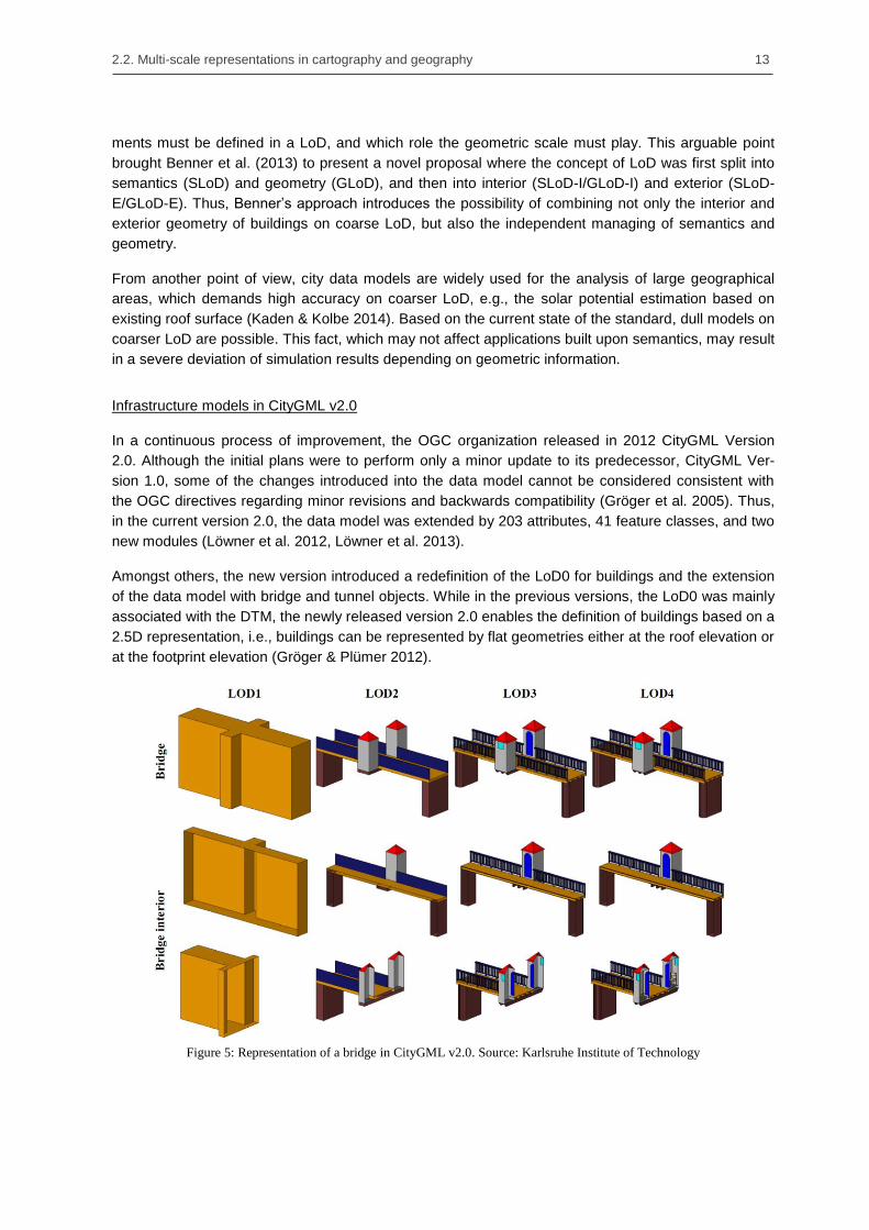
Amongst others, the new version introduced a redefinition of the LoD0 for buildings and the extension
of the data model with bridge and tunnel objects. While in the previous versions, the LoD0 was mainly
associated with the DTM, the newly released version 2.0 enables the definition of buildings based on a
2.5D representation, i.e., buildings can be represented by flat geometries either at the roof elevation or
at the footprint elevation (Gröger & Plümer 2012).
Figure 5: Representation of a bridge in CityGML v2.0. Source: Karlsruhe Institute of Technology

14 Chapter 2. State of the art in multi-scale infrastructure design
Figure 6: Representation of a tunnel in CityGML v2.0. Source: Karlsruhe Institute of Technology
The need of bridge and tunnel modules became apparent during the practical implementation of 3D
city models (Löwner et al. 2012). Unlike building models, both infrastructure facility elements have the
characteristic of interacting actively with the territory they were placed into, i.e., with the DTM model
represented in LoD0. Therefore, and contrary to the improvements implemented in LoD0 for buildings,
the bridge and tunnel modules were defined based on the previous four LoD approach. Figure 5 and
Figure 6 depict the four LoD, from LoD1 to LoD4, as defined by CityGML v2.0.
In contrast to buildings or bridges, where a fair distribution of information can be made based on the
geometric shape and detailing of surface elements, in tunnels the major part of information is placed in
their inside and hidden under ground. This below-surface property of tunnels was considered as the
triggering feature that might allow a different definition of their LoD. However, as the boundary be-
tween objects placed above- and under-surface can only be determined by the DTM, and this is not
always known with precision (when not missing), this approach was considered as violating the
CityGML unity of objects and was therefore rejected (Gröger & Plümer 2012). The impossibility of
defining tunnels under other LoD approaches, meant that the main information was constrained to
LoD4, reducing the practical applicability of the tunnel module.
The tunnel module of CityGML divides first the complete infrastructure into smaller TunnelParts. These
frequently represent the tunnel objects that are constructed for each travelling direction. Once the
tunnel parts are defined, their LoD are distributed as follows: LoD1 defines the external shape of the
tunnel, which is used to calculate its enclosing volume; in LoD2, its semantic and external geometry is
refined by the definition of several function surfaces, e.g., wallsurface, roofsurface and groundsurface;
in LoD3, openings like doors can be introduced as thematic objects; and LoD4 enables the definition
of interior objects such as an installation or hollow spaces (Gröger et al. 2012, Borrmann et al. 2015a).
Figure 6 shows one example of a tunnel represented with CityGML and Figure 7 depicts the UML
diagram of the tunnel module as defined by the standard.

2.3. Parametric CAD systems – procedural and assembly modeling 15
Figure 7: UML diagram of the CityGML tunnel model. Source: Gröger et al., 2012
2.3. Parametric CAD systems – procedural and assembly modeling
The concepts underlying parametric CAD systems where developed in the mid-1980s and first imple-
mented in a commercial product by Pro/ENGINEER in 1988 (PTC, 2016). Nowadays parametric CAD
systems are not only the state-of-the-art in automotive and aeronautical industries, but also in naval
and train-construction as well as machinery and manufacturing.
One of the reasons for this success is the different approach they implement in comparison with
conventional CAD systems. First, parametric CAD systems implement a combined model structure
approach, i.e. they offer the possibility of designing geometric models using diverse technologies (e.g.
free-form modeling, surface modeling and procedural modeling) and to integrate any of those models
in a common assembly environment (Baumann 2004). This flexibility reduces the size of the resulting
files and allows engineers to share single components in a reliable way.

16 Chapter 2. State of the art in multi-scale infrastructure design
Secondly, procedural geometric models maintain the construction steps needed to re-build the model
instead of keeping the final outcome geometry. Moreover, procedural models define dependencies
between these construction steps – also known as procedural or construction operations – that allow
designers to modify a single operation while the system updates the entire geometry in a consistent
manner.
In addition to the different modeling technologies parametric CAD systems support, different software
companies have been developed domain-specific modules for individual tasks. The idea behind these
modules is to respond to specific needs of specific industries. Thus, CAD modules such as piping or
cable routing, and integration modules for CAM or CAE became available to almost all commercial
software.
The remainder of this section is divided into four main topics: (1, 2) a comprehensive description of
procedural models and its dependency relations is done; (3) the limitations of the feature granularity
are reported; and (4) the basic concepts on assembly modeling and assembly structuring introduced.
2.3.1. Basic concepts in procedural modeling
Parametric sketches and construction history models
Modern parametric CAD systems implement a hybrid approach, based on the combination of 2D
parametric sketches with the principle of procedural geometric modeling, where the applied construc-
tion operations are recorded. In particular, 2D parametric sketches are flexibly defined by dimensions
and constraints, and solved as single entity, while 3D volumes are created and modified through the
consecutive application of construction operations such as extrusion, rotation, or Boolean operations
between solids (Shah & Mäntilä 1995, Monedero 2000, Betting & Shah 2001).
Parametric sketches are defined by three different types of objects: geometry elements, e.g. points,
lines and circles, geometric constraints, and dimensional constraints. From the two types of con-
straints, geometric constraints apply geometrical relations between pairs of geometry elements that
specify their relative position (Sitharam et al., 2006). Figure 8 depicts some of the typical geometric
constraints available in major parametric CAD systems.
Figure 8: Geometrical constraints typically provided by parametric CAD systems
Dimensional constraints, on the other hand, are used to restrict the size or the position of geometric
elements. Furthermore, each dimension comprises a parameter that can be defined as a static value
or as an algebraic equation where other parameters can be interrelated. Combined, these two types of
constraints (geometric and dimensional) enable the generation of complex 2D designs that capture the
design intent and provide a high degree of flexibility (Regli, et al. 2000, Chandrasegaran et al. 2013).
Figure 9 and Figure 10 show two sketches where typical geometric and dimensional constraints have
been applied.

2.3. Parametric CAD systems – procedural and assembly modeling 17
Figure 9: Example of application of geometric constraints in a 2D sketch
Figure 10: Example of application of dimensional constraints in a 2D sketch
In a different way, construction operations provided by parametric CAD systems can be classified into
three different groups:
Creation or sketch-based operations need at least one sketch to create a volume. Typical
operations are: extrusion, rotation and sweep operations. In Figure 11 a tunnel section is cre-
ated by means of a parametric sketch and an extrusion operation.
Modification or non-sketch-based operations are applied directly to a volume and do not
need a sketch to be performed. Typical operations are: fillet, chamfer and Boolean operators.
Auxiliary geometry operations create additional reference geometry needed to complete the
construction task. Typical features are: work-planes, work-axes, and work-points. One exam-
ple can be found in Figure 16 where a work-plane is defined perpendicular to a 3D spline at a
given point. Later on, this work-plane can be defined as the reference surface for a parametric
sketch.

18 Chapter 2. State of the art in multi-scale infrastructure design
Figure 11: (left) parametric sketch of a tunnel cross-section and (right) 3D extruded tunnel
An important aspect that distinguishes parametric sketches from the construction history approach in
procedural models is the approach they use to solve the geometric problem. Parametric sketches
define the geometric constraint problem independently of the sequence its dimensions and constraints
were introduced, in a methodology known as a variational approach (ISO 10303-55 2005a). Different-
ly, in the construction history the construction operations are sequentially retrieved, in a methodology
known as procedural approach (Shah and Mäntilä 1995, Anderl and Mendgen 1998).
The variational approach handles the geometry and constraints defined in a parametric sketch as
geometric-topological elements, whose size and placement must be calculated depending on the
values of their parameters (Hoffmann & Joan-Arinyo 2005, Bettig and Hoffmann, 2011). A simple
example is a triangle sketch defined by three lines, three dimensions and the necessary geometrical
constraints. Thus, for a single set of topological elements, the variational approach will return different
geometric solutions depending of the value defined on their parameters.
Parametric CAD systems use Geometric Constraint Solvers (GCS) to accomplish this task. Every time
a topological modification in the sketch is introduced or one of the dimensions is updated, the GCS will
start the solving process. If the number of constraints (geometric and dimensional) equals the degree
of freedom of the system, the GCS will return an updated size and placement for the different topolog-
ical elements. However, if the system is defined with too many or insufficient constraints (over- or
under-constraint) the GCS will not be able to find a solution and a warning message will be prompted
(Jubierre, 2009).
On the contrary, the procedural approach employed on the construction history generates the final
model by sequentially applying construction operations to the previously evaluated geometry. Unlike
the variational approach, changes in the sequence of operations may end in different outcome geome-
try.
Parametric sketches vs. 2D drawings: a critical change in engineer‘s methodology
The introduction of the technology of parametric sketches by parametric CAD systems changed the
workflow engineers used to create digital models. Before the appearance of parametric technologies,
engineers employed conventional CAD systems as computerized tools that allowed them to overcome
the shortcomings of drafting tables without the need of redefining the design process. In particular,
conventional CAD systems used the geometry as base element to which auxiliary information, in the
form of text or dimensions, was attached. Hence, engineers used CAD systems as documentation and

2.3. Parametric CAD systems – procedural and assembly modeling 19
not as design tool (Sacks et al. 2004). As a simple example, Figure 12 depicts one drawing of the
typical cross-section of a single-track shield tunnel, where engineers represent geometry and seman-
tics.
Later on, and because both technologies, drawing and sketching, manipulated similar geometric
elements, an initial attempt of importing old drawings into modern sketches was observed. Obviously,
this approach did not succeed and drove engineers to clearly differentiate the application areas of both
technologies. Thus, McConnell (2010) distinguished drawings and parametric sketches with the two
following statements:
“A drawing is a collection of geometry (lines, points, and arcs) laid out in a 2D format.
These geometric elements, which have no relation to each other, are used to determine
the final prints.”
“A sketch is a collection of geometry (lines, points, and arcs) coupled with relationships
(parameters, equations, dimensions, and sketch constraints) laid out in a 2D format.
These geometric elements are related to each other to reflect design intent. These
sketches are used to define 3D geometry, which is then projected to 2D for the final
prints.”
Moreover, parametric sketches introduced a novel concept; ―Shape before size – creating rough
sketches‖ (Shih 2014). Due to the ability of parametric sketches to update the outcome geometry
every time a dimension or constraint was added or modified, engineers were allowed to roughly sketch
the design concept and slowly update the resulting geometry as design decisions were taken.
Figure 12: Drawing of a tunnel cross-section as represented by conventional CAD systems
(Source: OBERMEYER Planen + Beraten GmbH)

20 Chapter 2. State of the art in multi-scale infrastructure design
Finally, parametric sketches introduced the practice of small and simple sketches in opposition to the
extreme complex and highly dense 2D drawings. On the one hand, engineers fragmented the design
process into several independent sketches that offered in return an easy modification of specific
elements of the design intent. On the other hand, the geometry of holes, fillets, and chamfers was
integrated in separated construction operations, reducing the complexity of the sketches and enabling
easier access through the construction history of the model.
Constraint solving approach on procedural modeling
Procedural models improved the design process by the introduction of parametric sketches and con-
struction operations. However, the underlying technology also introduced new shortcomings due to the
evaluation need of the input information to produce the outcome geometry. This evaluation process
takes place with every modification of any construction operation and may result in an unforeseen
solution or even in a non-evaluable model.
First, ambiguous solutions can arise during the evaluation process of parametric sketches. Despite the
fact that a GCS needs a well-constraint sketch to be able to start a new calculation, this fact by its own
is not able to guarantee a solution. Even more, the following three issues regarding the identification of
non-evaluable solutions have been reported for long time in literature:
In the evaluation process the topology of the parametric sketch is converted into a set of
mathematical equations that can be handled by the solver. Then, the GCS tries to solve the
mathematical problem together with the instance value of its parameters. However, the solver
may find out that no feasible solution is possible for the topology and parameters provided.
This fact can be easily observed in Figure 13. This example, originally from Fudos and Hoff-
mann (1997), shows that the solver will not be able to return a solution if one dimension is
larger than the added value of the other two.
Figure 13: Parametric sketch that is not always solvable by a GCS. Author reproduction based on
Hoffmann 1997
Hoffmann and Joan-Arinyo (2005) also show that for some configurations of the sketch prob-
lem there is an infinite number of solutions. Figure 14 shows the sketch they used to illustrate
this problem. Thus, for the combination of angle values of 90° the point P can be placed eve-
rywhere along the line defined through the points A and B.

2.3. Parametric CAD systems – procedural and assembly modeling 21
Figure 14: The position of the point P (left) is defined at the intersection of the two lines defined by
the angles a and b. The position of the point P (right) cannot be determined based on the actual con-
straint problem. Author reproduction based on Hoffmann and Joan-Arinyo (2005)
Finally, Joan-Arinyo & Soto (1997) reported that for a single topological problem there is al-
ways a collection of feasible mathematical solutions. Choosing the expected right solution
from this collection has been classified as a NP-hard problem (Mata & Kreinovich 1998).
Therefore, GCS usually implement a complex heuristic method that returns to the user the
closest feasible solution to the initial sketched problem. Figure 15 shows an example of four
feasible mathematical solutions of the same topological irregular quadrilateral problem.
Figure 15: Four feasible mathematical solutions of the irregular quadrilateral problem (Source: Joan-Arinyo
et al. 2002)

22 Chapter 2. State of the art in multi-scale infrastructure design
Secondly, unforesen solutions can emerge during the sequential evaluation of the construction history.
On the one hand, even if a single modification of one construction operation is consistent, its evalua-
tion in relation to its dependent operations may end up in a non-evaluable geometry; for example, if
the inner-diameter of one tunnel is modified and becomes larger than the outer-diameter. Despite both
operations can be evaluated, the Boolean cutting operation will not be able to return a solution and the
system will prompt a non-evaluable message.
On the other hand, parametric CAD systems implement a dual representation based on the procedural
description and its evaluated boundary representation geometry. The problem itself does not remain in
this dual representation, but in the fact that later aggregated construction operations may establish
references to non-persistent topologic entities of the evaluated boundary representation. Consequent-
ly, parametric references to such entities can become ambiguous preventing any modification of the
model. This behavior is known as the persistent naming problem and has been classified as the most
serious problem in parametric modeling (Marcheix & Pierra 2002, Bidarra et al. 2005, Wang & Nnaji
2005).
These unavoidable geometric issues have to be added to the non-existent dependency analysis and
the poor capabilities parametric CAD systems provide to manage them. This fact leads to severe
difficulties for engineers and designers to foresee the consequences of their changes. Anderl and
Mendgen (1996) stated that in highly parameterized models a single change can trigger a domino
effect that may end up in the collapse of the complete model.
“Real life models using parametric functionality very rapidly become too complex to
keep an overview of the evolving structure and the relations between the components of
this structure. The effect is that the creation of a parametric model often ends up in a
model crash, meaning that the designer is no longer able to modify the existing model
without causing changes he did not intend in consequence.”
In this thesis, novel techniques are presented that help to avoid the aforementioned problems. Thus,
procedural model robustness is defined as the capability of a procedural model to be modified
resulting in a geometry that matches the intended solution.
2.3.2. Dependency relations in procedural models
As mentioned before, one important characteristic of procedural models is the available construction
history defined in the modeling process. In addition, within the creation of the construction history,
relations between operations are automatically generated by the parametric CAD system in a manner
transparent to the end user. These relations can be understood as dependencies and allow the para-
metric CAD system to properly update the related geometry when an operation is modified or deleted
(Shah and Mäntilä 1995, Bodein et al. 2014).
A simple example of such dependencies can be found in the relation between an extrusion and a
parametric sketch. Normally, the designer begins with the definition of the sketch and after defining the
height parameter, the CAD system creates the extruded volume and the dependency between both
operations. Moreover, this dependency clearly defines a direction – the dependency goes from the
parametric sketch to the extrusion – indicating that the two operations cannot be swapped in the
construction history, as no extrusion can be created before its outlining geometry.

2.3. Parametric CAD systems – procedural and assembly modeling 23
Figure 16: Parametric tunnel (top) modelled by seven construction operations (left) and its dependency dia-
gram (right)
As a consequence, the geometric operations and their dependencies represent a directed acyclic
graph (DAG) where the nodes are the construction operations and the edges the dependencies be-
tween them. This novel representation is called dependency diagram. Although the dependency
diagram is unique for a given set of operations generating a desired geometric result, the sequence of
executing operations is not necessarily fixed. Thus, the swapping of two operations is possible when
they are consecutive and there is no direct dependency between them. This property of the construc-
tion history can be easily seen in the example depicted in Figure 16, where despite some operations
can be swapped – the two sketches (operations 3 and 4) or the two sweep operations (operations 5
and 6) – neither the dependency diagram nor the resulting geometry are altered.
Finally, parametric CAD systems can manage procedural models that define several disconnected
bodies. A disconnected body is defined as a set of construction operations that do not create depend-
encies on any other operation present in the construction history. The corresponding dependency
graph becomes a disconnected subgraph. This behavior plays a key role in the design of infrastructure
models because it enables the subdivision of the complete project into a set of submodels that can be
treated independently (Jubierre and Borrmann. 2013). Because of its relevance this approach will be
intensely discussed and analyzed in the following Chapters 4 and 5 of this thesis.
2.3.3. The granularity problem on procedural models – The cellular model
One difficulty that impedes the exchange of procedural models between CAD systems is the different
granularity the same construction operation implements among different parametric systems. In fact,
parametric CAD systems are usually based on the feature approach rather than on the construction
operation approach. The feature approach includes several construction operations executed at the
same modeling step (Chen and Hoffmann 1995, Pratt and Kim 2006, Bodein et al. 2014). Figure 17
depicts one example based on the extrusion feature in Autodesk Inventor. This enables not only the
definition of the parameters and direction of the extrusion, but also a Boolean union with its predeces-
sor operation, and the possibility of choosing between a solid or surface outcome.

24 Chapter 2. State of the art in multi-scale infrastructure design
Figure 17: Extrusion feature in Autodesk Inventor. For this simple feature, the user can define, in addition to
the parameters and direction of the extrusion, a Boolean union and between solid/surface outcomes.
One method to overcome this granularity limitation is known as cellular representation schemes or
cellular model (Bidarra et al. 1998). First introduced by Pratt (1988), the cellular model divides the
output geometry in a set of sub-volumes lying either internal or external to the solid part and wrapped
around its minimal containing box. There is no evidence that this method, as defined by Pratt, was
ever implemented.
The intrinsic history-independence of the cellular model approach made researchers to develop new
hierarchical structures. Thus, Rossignac (1990) presented the Selective Geometric Complex (SGC).
This is a cellular model that permits the representation of cell objects with an internal decomposition
structure, making this approach an attractive choice for representing potentially overlapping features.
Further research in this field conducted Gomes et al. (1993) to enhance the proposal of Pratt with a
hybrid approach, where a hierarchical structure of modeling steps is stored in addition to the explicit
outcome. This approach demands the extensive use of mate constraints between the geometric cells
that make this methodology complex and inefficient.
In summary, cellular models are a good alternative when only the geometric representation must be
exchanged. Due to the fact that cellular models are mainly history-independent, it is almost impossible
to reconstruct the design intent the engineer or designer applied during the modeling process. Alt-
hough some developments were made to incorporate the construction history, these methods were
shown complex and inefficient in comparison with the existing procedural method.
2.3.4. Basic concepts in assembly modeling
The design of complex engineering systems demands the integration of diverse components devel-
oped by different experts. Such integration can be seldom achieved by the single procedural modeling
of parts and components. Therefore, in parallel to procedural modeling, parametric CAD systems
introduced a novel technology that allows engineers to integrate several modeled components in an
assembly environment (Noort et al. 2002). This technology not only permits engineers and experts to
work in a more flexible manner, but also opens the door to drive engineering simulations, e.g. contact
and kinematic analysis, collision detection, and assemblability evaluation (Shah and Mäntylä 1995).

2.3. Parametric CAD systems – procedural and assembly modeling 25
In general, assembly models can be understood as a tree structure consisting of nested assemblies
and parts. By definition, every assembly contains a root node – also known as chassis or master piece
(Shah and Rogers 1993, Baumann 2004) – that has a fixed reference to the global coordinate system
(GCS). Moreover, the leaves of the assembly model establish spatial relationships among themselves
and within the root node that enables the correct placement of the leaves when the root node is
moved or modified.
Another important concept of assembly modeling is the occurrence approach. In particular, the leaves
on the assembly structure are not the modelled parts themselves but displayed instances, known as
occurrences, describing their placement and orientation in space. This approach allows parametric
CAD systems to handle large amount of parts with minimal amount of information (van Holland &
Bronsvoort 2000). The limitation on this approach remains in the fact that the assembly model by itself
does not contain any geometric information but references to the original parts and their positioning in
space. Therefore, managing part and assembly files, externally to the CAD system, become a time-
consuming and error-prone process.
As mentioned before, the aim of spatial relationships is to restrict the degrees of freedom (DOF)
occurrences have in space. In order to reduce the tedious work such relationships demand, parametric
CAD systems implement the concept of mating features (Lee and Gossard 1985, Shah and Tadepalli
1992). Similarly to procedural modeling, where the modification of the outcome geometry is managed
by construction operations, assembly modeling encapsulates several spatial relationships by a set of
mating constraints. Additionally, as the assembly model can drive engineering simulations, a dual
classification of mating constraints has been widely established regarding the final purpose of the
constrained model (Chen & Perng 1997):
Geometric mating defines spatial relationships based on geometric properties between parts.
For example: two axes must be co-linear, two planes must be perpendicular or two curved
surfaces must be tangent.
Kinematic pairs also known as kinematic joints, define spatial relationships based on kine-
matic interaction between parts, e.g., screw-pair, cylindrical-pair, or spherical-pair.
Since large infrastructure facilities are considered static rather than dynamic, kinematic-pairs will be
excluded from further discussion in this thesis.
Part positioning
Although parametric CAD systems mainly implement the approach of mating constraints to achieve
spatial restrictions among parts, other methodologies have been developed and reported by literature
(Baumann 2004). Thus, in addition to mating constraints, positioning by (relative) coordinates became
the standard constraint methodology extensively implemented by neutral product models such as
STEP or IFC.
The main weakness of constraining by coordinates remains in the fact that every time a part model is
modified, the coordinate system of the related parts must also be updated. However, this limitation is
rarely taken as a real drawback, since neutral product models are intended for exchanging assembly
information and not for supporting dynamic design processes.
Differently, positioning by mating constraints establishes constraint relations between pairs of parts.
Each half-constraint, also known as mate, is applied either to one surface of the geometry or an auxil-
iary construction operation of the procedural model. Furthermore, the majority of mating constraints
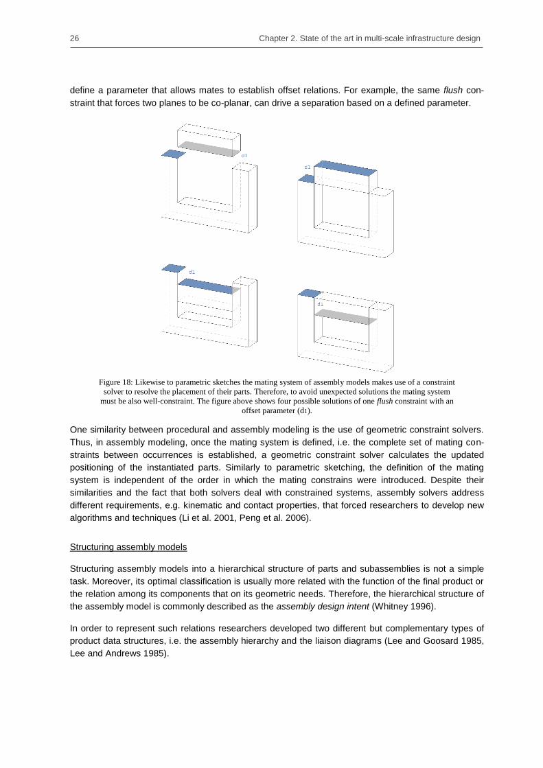
26 Chapter 2. State of the art in multi-scale infrastructure design
define a parameter that allows mates to establish offset relations. For example, the same flush con-
straint that forces two planes to be co-planar, can drive a separation based on a defined parameter.
Figure 18: Likewise to parametric sketches the mating system of assembly models makes use of a constraint
solver to resolve the placement of their parts. Therefore, to avoid unexpected solutions the mating system
must be also well-constraint. The figure above shows four possible solutions of one flush constraint with an
offset parameter (d1).
One similarity between procedural and assembly modeling is the use of geometric constraint solvers.
Thus, in assembly modeling, once the mating system is defined, i.e. the complete set of mating con-
straints between occurrences is established, a geometric constraint solver calculates the updated
positioning of the instantiated parts. Similarly to parametric sketching, the definition of the mating
system is independent of the order in which the mating constrains were introduced. Despite their
similarities and the fact that both solvers deal with constrained systems, assembly solvers address
different requirements, e.g. kinematic and contact properties, that forced researchers to develop new
algorithms and techniques (Li et al. 2001, Peng et al. 2006).
Structuring assembly models
Structuring assembly models into a hierarchical structure of parts and subassemblies is not a simple
task. Moreover, its optimal classification is usually more related with the function of the final product or
the relation among its components that on its geometric needs. Therefore, the hierarchical structure of
the assembly model is commonly described as the assembly design intent (Whitney 1996).
In order to represent such relations researchers developed two different but complementary types of
product data structures, i.e. the assembly hierarchy and the liaison diagrams (Lee and Goosard 1985,
Lee and Andrews 1985).

2.4. Data exchange based on Product Models 27
Figure 19: Assembly model and hierarchy structure of a simple shield tunnel. The main assembly comprise
two subassemblies, which are differenced occurrences of the same ring assembly model
Also known as part-of graphs (Mäntylä 1988), the assembly hierarchy describes the basic structure of
the assembly model. Specifically, two main approaches have been developed to represent assembly
models: the Bill-of-Material (BOM) and the part-list structure. A BOM can be seen as a flat table where
each entry represents a different part or subassembly model. Additional information such as the num-
ber of occurrences, material properties, and standard regulations (if any) is frequently attached. By
contrast the part-list structure is defined as a specific BOM represented in a tree structure where each
occurrence is counted (Rachuri et al. 2006). Although only part-list structures exactly reproduce the
assembly hierarchy, BOM are very useful when managing or exporting external modeling references.
As initially developed, liaison diagrams represented the simplest assembly connectivity among parts,
regardless of what constraints were involved to create the mating (Bourjault, 1984). Posterior devel-
opments introduced the possibility of recording additional information, such as type of constraint or
number of neglected degrees of freedom (Whitney et al. 1999). Nowadays, the capability of liaison
diagrams of representing connectivity among parts placed in different subassemblies plays a key role
in the automatic definition of simulation scenarios.
2.4. Data exchange based on Product Models
Already in the early years of the CAD development, the challenges inherent to the exchange and
integration of information were identified. The following quoted statement was published at the same
conference where Sutherland presented Sketchpad, widely considered the first CAD system.
“There are a great many existing specialized languages and programming systems for
many of the individual areas which must be covered by a Computer-Aided Design sys-
tem, […] so that it would be completely impractical to attempt to integrate such sys-
tems in a straight-forward manner” (Ross & Rodriguez 1963)
Although the initial attempts of exchanging information between CAD systems were successfully
accomplished by the use of neutral data formats covering pure geometric information, additional non-

28 Chapter 2. State of the art in multi-scale infrastructure design
geometric data such as material properties, construction dates, or involved cost, were not recognized
and therefore lost in the exchanging process. In response to this limitation, the definition of neutral
data models were extended to integrate the previously neglected semantic information together with
the geometry representation in a novel product model concept, and defined as:
“A product model is a computer-interpretable, complete and unambiguous description
of the product being designed, constructed, and operated. It supports the communica-
tion between computer-aided activities by storing all the information that needs to be
exchanged within the project” (Bakkeren & Tolman 1994)
Additionally, product models implement a flexible, object-oriented structure with a clear separation
between semantics and geometric representations. This clear separation promoted, in short time, the
definition of new semantic models for a large range of field-specific domains. Following this direction,
this thesis presents a novel proposal for a multi-scale shield tunnel product model.
The remainder of this section is structured as follows: first, an overview on the historical background
and main benefits and drawbacks of product modeling are discussed; then, the two most widely
adopted exchange standards – STEP and IFC – are analyzed; finally, the current IFC extensions for
infrastructure modeling are reported.
2.4.1. Overview
As already introduced, the first attempts on exchange of information focused mainly on geometry. So,
this subsection gives a brief survey on the historical background of data exchange based on neutral
data formats and its increasing complexity. Finally, the benefits and drawbacks of modeling exchange
based on neutral formats are pointed out.
Historical background on exchange standards: The IGES data format
As Wilson reported (Wilson 1987), the first real need for exchange of information appeared in the
1970‘s between CAD/CAM systems. To answer this need, the National Bureau of Standards of the US
published in 1978 the first version of ―Initial Graphics Exchange Specification” (IGES) with the initial
scope of exchanging ordinary geometric, graphical, and annotated entities required in blueprints. Thus
with this broad objective, IGES soon became too slow on its developments, which fostered other
national standards to appear and to try to fill this gap.
From the several emerging initiatives, three materialized in the following years. In 1983, a new surface
modeling interface known as VDA-FS2 was released for enabling the transfer of free-form curves and
surfaces with a degree greater than 3 (VDA 1986), which became part of the standard DIN66301, in
1986. Later on, in March of 1984, the first revision of the French proposal SET3, was published, focus-
ing on the size of the files to be transferred. The SET proposal suggested a totally new approach
based on a new file format that enabled data sharing between records. The SET proposal became
standard in 1985 under the AFNOR Z 68300. Finally, in October 1985, the second task of the PDDI4
project was finished and published, focusing on the transfer needs for four selected benchmark parts
typically used by the aerospace industry. Despite new file structures were designed and new transla-
2 Verband der Automobilindustrie - Flächenschnittstelle
3 Standard d’Échange et de Transfert
4 Product Data Definition Interface

2.4. Data exchange based on Product Models 29
tors were implemented, the PDDI project was never included on an international standard (Vries-
Baayens 1991).
As counterpart to the alternative initiatives, four new versions of the IGES standard appeared in the
following years. However, none of them were able to fix the intrinsic problems on the standard, namely
the excessive file size and processing time, numerical sensibility of some geometrical definitions, and
ambiguities in its specification (Encarnacao 1986, Wilson 1987).
In December of 1983, in an attempt to address the IGES limitations and at the request of the United
States and France, the International Standards Organization (ISO) created the Technical Committee
TC184/SC4 with the aim of integrating the arising proposals under a new, more complete, standard
called STEP (STandard for the Exchange of Product model data). Its development was divided into
smaller parts, known as Application Protocols (AP), with the confidence of reducing the complexity of
such a wide spectrum of knowledge. Although this subdivision and the arising coordination tasks
resulted in the first AP not to be published until 1994, the comprehensive results, which prolonged
over more than ten years, claimed STEP to be the first product model able to exchange not only
geometry, but also semantics.
Benefits and drawbacks on information exchange based on product models
Since the first CAD systems appeared on the market, CAD vendors developed their own file formats,
frequently referenced as internal or native, to store the information generated by the user. This fact
was not a problem at early adoption, but as the number of vendors increased, the exchange of infor-
mation became no longer possible.
Traditionally, two different approaches have been followed to overcome this problem. First, on the
approach known as ―direct translation‖, the sending CAD system translates its native file into the
native format of the receiving system. This approach comprises two clear benefits (Vries-Baayens
1991):
Direct translators can have an optimal performance.
A complete transfer of data is achievable because only one mapping is involved.
However, this approach presents a serious drawback. As the number of CAD systems increase, the
number of needed translators grows in an exponential ratio.
Figure 20: Exchange methods on CAD systems. (left) Direct translation and (right) exchange based on neutral
file format. Author reproduction based on Vries-Baayens 1991.
The second approach is based on the use of a shared or neutral product model. The basic idea re-
sides in the definition of a common description of a neutral file format that all CAD systems can trans-

30 Chapter 2. State of the art in multi-scale infrastructure design
late. As consequence, CAD systems need only from two translators, one to write down in the neutral
product model (pre-processor) and other to read from it (post-processor). The benefits of neutral file
format approaches are (Vries-Baayens 1991):
A CAD vendor can handle any change in its system by updating its pre- and post-processors.
A new CAD system only needs two translators to communicate with all the other systems, a
clear advantage to the 2*N translators needed by the direct approach.
Product models can be stored in a system-independent open format, which is of special inter-
est for products with a long lifecycle.
The main drawback on the exchange based on neutral file formats remains in the fact that neutral
models cannot cover the complete information defined by different CAD systems. Although the ex-
change of geometric representations is currently achieved in a large ratio, the main limitation is fre-
quently associated with the specific semantic information that domain-specific CAD systems imple-
ment. Therefore, if the CAD system defines a different or extended semantic model than the neutral
model, a double loss of information will be undergone, i.e. at the time of the exporting (pre-processor)
and at the time of importing (post-processor).
Figure 21: Main drawback of neutral formats. The transferred information is only a portion of the original
generated by the CAD system. Author reproduction based on Vries-Baayens 1991.
2.4.2. The ISO-STEP standard
Background
Resulting from the experiences gained with the IGES standard, it was clearly recognized that the
available neutral data models had elementary limitations not easy to overcome or to correct. In 1984,
these weaknesses compelled the International Standards Organization (ISO) to create the Technical
Committee TC184/SC4 with the task of developing a new exchange standard that addressed the main
limitations of the existing efforts. Named STEP (STandard for the Exchange of Product model data)
the new standard was born under the umbrella of ISO 10303 – Industrial Automation Systems – Prod-
uct Data Representation and Exchange (Pratt 2001).
Several goals were identified with a higher priority (Eastman 1999):
Incorporating new programming language concepts.
Separating the data model from the physical file format.

2.4. Data exchange based on Product Models 31
Supporting the clustering of the model, avoiding in this way the overhead produced by the
manipulation of the complete data model.
Supporting alternative physical level implementations, e.g., files, databases, and knowledge-
based systems.
Incorporating reference models, commonly shared by large standard models.
Ten years later, in 1994, the first version of the ISO-STEP was released. Due to the complexity of its
development, the standard was divided into ten sections denoted as Parts. From them, Part 203
enabled the exchange of product shape representations built upon wireframe, surface, and boundary
representations. Though Part 203 became rapidly the most implemented standard among commercial
CAD systems, the first version of this part had a serious drawback; once the geometry was transferred
into the receiving system, it cannot be modified efficiently (Pratt et al. 2005).
The main reason for this limitation was found in the change of the design strategy that engineers
implemented during the ten years the first version of the standard needed to be released. Thus, in the
mid-1980s boundary representations were state of the art, while in the 1990s, the parametric approach
took over this critical gap. This evolution on the design strategy demanded major updates on Part 203,
which were published in 2005 and 2011.
In addition to the updated versions, several additional parts were released to address specific issues
on parametric modeling. In doing so, two main parts were released in 2005 and one in 2007. Part 55
provided definitions for procedural and hybrid models in a general way, while Part 108 provided means
for the flexible definition of parametric sketches. Released later on, Part 111 summarized the devel-
opments in form features that initially were enunciated as a draft by Part 48 (Shah & Mathew 1991,
Shah & Mäntilä 1995, Pratt & Kim 2006). These three parts of the standard will be reported in detail in
the next section.
Several organizations performed proof-of-concept experiments to evaluate the exchange capabilities
of the different STEP parts. The most comprehensive and well-documented study was performed by
PDES Inc. in the scope of the CHAPS (Construction History And ParametricS) program (Pratt et al.
2005). This project embraced six engineering companies, three commercial CAD systems, and one
software company responsible for the STEP translators. The results of this program shown that up to
two-thirds of the model exchange was successfully achieved without human intervention and that the
remaining third was achieved after slight manual modification of the procedural models. The insight
gained from the conducted experiments was submitted to the ISO organization to improve the next
releases of the standard (Stiteler 2004).
Modular architecture of STEP
One of the key decisions at the beginning of the STEP‘s development was the division of the standard
into several partial models, called Application Protocols (APs). In particular, this decision enabled
different working groups to concentrate on specific problems while producing useful results in shorter
time. Later on, combinations of multiple APs would be encapsulated into Application Interpreted Con-
structs (AIC) to create larger domain-specific models (Kemmerer 1999, Feeney 2002).
Consequently, the STEP architecture was divided into five different parts around the concept of APs.
Although this initial division was slightly updated at the end of the 1990s, its architecture and main
components still remain valid, and therefore will be analyzed.

32 Chapter 2. State of the art in multi-scale infrastructure design
Figure 22: Diagram of the different components that conforms the ISO-STEP standard. Dash lines (4) indi-
cate language use and dash arrows (3) indicate a usage of the module. Thick lines (2) indicate reuse of exist-
ing modules and thick arrows (1) indicate a mapping realized by a translator. Author reproduction based on
Eastman 1999
The five main components, as described by Eastman (1999), are:
Description methods. These modules describe the varying modeling languages employed in
the definition of the different information models, namely, Integrated Resources (IRs), Applica-
tion Reference Models (ARMs), and Application Interpreted Model (AIMs). The supported lan-
guages are NIAM, IDEF1x, EXPRESS and EXPRESS-G.
Integrated Resources (IRs). These modules provide common model subsets employed by
several Application Models (AMs). Integrated resources are split into the following:
o The Integrated Generic Resources are shared subsets across multiple application
domains and describe general elements such as geometry, material, and tolerances.
o The Integrated Application Resources are specific subsets for given industries, e.g.
kinematics, finite elements, and electrical applications.
Application Protocols (APs). These modules are developed for specific application scenari-
os and built upon Integrated Resources (IRs) and description methods. APs are made up of
two different components:
o The Application Reference Model (ARM) represents the requirements for designing
and assessing the information model of an application. ARMs are written using graph-
ical modeling languages such as EXPRESS-G or NIAM, which makes these modules
readable not only for computers but also for expert users.
o The Application Interpreted Model (AIM) is the result of interpreting an ARM and
resolving its interactions with generic integrated resources.
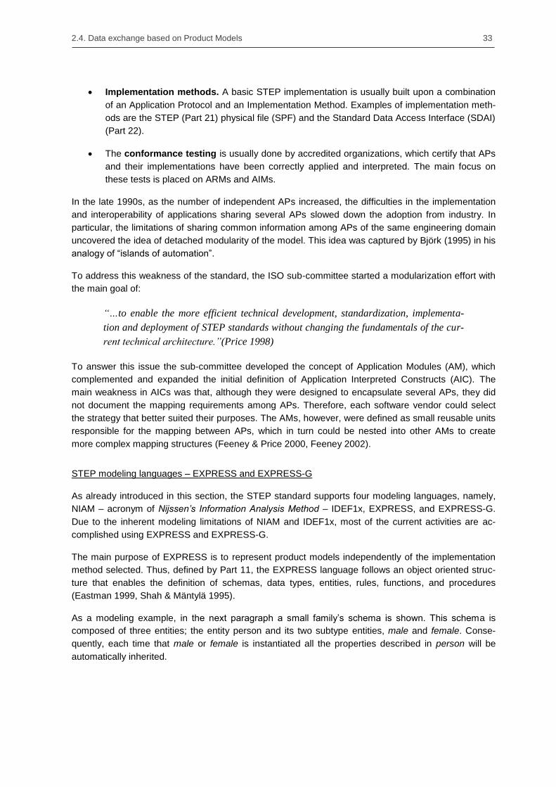
2.4. Data exchange based on Product Models 33
Implementation methods. A basic STEP implementation is usually built upon a combination
of an Application Protocol and an Implementation Method. Examples of implementation meth-
ods are the STEP (Part 21) physical file (SPF) and the Standard Data Access Interface (SDAI)
(Part 22).
The conformance testing is usually done by accredited organizations, which certify that APs
and their implementations have been correctly applied and interpreted. The main focus on
these tests is placed on ARMs and AIMs.
In the late 1990s, as the number of independent APs increased, the difficulties in the implementation
and interoperability of applications sharing several APs slowed down the adoption from industry. In
particular, the limitations of sharing common information among APs of the same engineering domain
uncovered the idea of detached modularity of the model. This idea was captured by Björk (1995) in his
analogy of ―islands of automation‖.
To address this weakness of the standard, the ISO sub-committee started a modularization effort with
the main goal of:
“…to enable the more efficient technical development, standardization, implementa-
tion and deployment of STEP standards without changing the fundamentals of the cur-
rent technical architecture.”(Price 1998)
To answer this issue the sub-committee developed the concept of Application Modules (AM), which
complemented and expanded the initial definition of Application Interpreted Constructs (AIC). The
main weakness in AICs was that, although they were designed to encapsulate several APs, they did
not document the mapping requirements among APs. Therefore, each software vendor could select
the strategy that better suited their purposes. The AMs, however, were defined as small reusable units
responsible for the mapping between APs, which in turn could be nested into other AMs to create
more complex mapping structures (Feeney & Price 2000, Feeney 2002).
STEP modeling languages – EXPRESS and EXPRESS-G
As already introduced in this section, the STEP standard supports four modeling languages, namely,
NIAM – acronym of Nijssen’s Information Analysis Method – IDEF1x, EXPRESS, and EXPRESS-G.
Due to the inherent modeling limitations of NIAM and IDEF1x, most of the current activities are ac-
complished using EXPRESS and EXPRESS-G.
The main purpose of EXPRESS is to represent product models independently of the implementation
method selected. Thus, defined by Part 11, the EXPRESS language follows an object oriented struc-
ture that enables the definition of schemas, data types, entities, rules, functions, and procedures
(Eastman 1999, Shah & Mäntylä 1995).
As a modeling example, in the next paragraph a small family‘s schema is shown. This schema is
composed of three entities; the entity person and its two subtype entities, male and female. Conse-
quently, each time that male or female is instantiated all the properties described in person will be
automatically inherited.

34 Chapter 2. State of the art in multi-scale infrastructure design
SCHEMA Family;
ENTITY Person
ABSTRACT SUPERTYPE OF (ONEOF (Male, Female));
Name: STRING;
Mother: OPTIONAL Female;
Father: OPTIONAL Male;
END_ENTITY;
ENTITY Female
SUBTYPE OF (Person);
END_ENTITY;
ENTITY Male
SUBTYPE of (Person);
END_ENTITY;
END_SCHEMA;
EXPRESS-based models are encoded using the ASCII standard and therefore readable for humans
and machines. However, as the model complexity increases, the overall human perception decreases.
To address this limitation and providing an easier insight of the model, the STEP initiative developed a
graphical notation called EXPRESS-G. The main weakness on EXPRESS-G is that this initiative was
just defined as a subset of EXPRESS without the possibility of specifying complex relations. Neverthe-
less, the robust combination of EXPRESS and EXPRESS-G made this mixed approach the most
advanced modeling methodology.
Figure 23: Graphical representation of the family’s schema using EXPRESS-G.
A widely accepted method of design exchange between STEP-conforming implementations is based
on the STEP-Physical File (SPF). Contained in Part 21, this AP describes how to represent data
according to a given EXPRESS schema. The SPF or STEP files are denoted by the extensions .step,
.stp and for some specific purposes .p21
ISO-10303-21;
HEADER;
FILE_DESCRIPTION (('A minimal STEP-File example'), '2;3');
FILE_NAME ('example', '2015-05-21T16:51:30', ('Javier Jubierre'),
('TUM CMS'), '0.1', '', '');
FILE_SCHEMA ((Family));
ENDSEC;
DATA;
#10 = MALE ('Adam', $, $);
#11 = FEMALE ('Eve', $, $);
#12 = MALE ('Cain', #11, #10);
#13 = MALE ('Abel', #11, #10);
ENDSEC;
END-ISO-10303-21;

2.4. Data exchange based on Product Models 35
In the example above, a small STEP file is instantiated from the schema depicted on Figure 23, where
a family composed by parents and two children is represented. The parents are instantiated without
reference to their ancestors, while the two children establish equal references to their parents.
Exchanging parametric models based on ISO-STEP Integrated Resources
One of the main characteristics of the STEP standard is its division into several modules called Parts.
Depending on their scope, parts are classified, among other modules, in Application Protocols (APs),
and Integrated Resources (IRs). As a rough description it can be said that APs handle semantic do-
main-specific descriptions, while IRs provide generic and applied resources transversal to any APs.
Traditionally, information exchanging processes have been implemented on the basis of explicit ge-
ometry representations such as Constructive Solid Geometry (CSG) or Boundary Representations (B-
rep). However, those processes do not allow the dynamic exchange of information built upon paramet-
ric geometry. To address this limitation, in the late 2000s the standardization committee released a set
of parts that focused specifically on this topic. Moreover, the division of parametric geometry into
several parts enabled hybrid geometric representations based upon procedural and explicit geome-
tries (ISO 2005b).
Figure 24: Pyramidal structure of the STEP standard extended with parametric parts (in blue). The basic ge-
ometric capabilities are provided by parts 41, 42 and 43, while part 55 contributes with the procedural model-
ing description. Parts 108 and 111 attach parameterization and procedural solid shapes to the basic geometric
definitions. The AP 214 and 242 are the first protocols that make use of parametric descriptions.
In particular, three new integrated resources were developed and incorporated into the modeling
structure of STEP. As an integrated general resource, Part 55 was defined as the first level of para-
metric integration, describing the geometry as a successive application of modeling steps. Whether
these steps were defined as parametric or explicit geometry elements was not relevant for this part.
This need was addressed by two later integrated application resources: Part 108 and Part 111. Part
108 gave the tools needed to describe geometry in a variational manner. Specifically, this part de-
scribed how parametric sketches can be exported and provided a list of explicit geometric constraint
definitions. Part 111 focused on the description of widespread feature construction operations such as
chamfering or blending. Finally, this strategy allowed independent standardization working groups to
develop domain-specific application protocols that make use of parametric representations. The first
reported application protocols were the Part 214, Core data for automotive mechanical design pro-

36 Chapter 2. State of the art in multi-scale infrastructure design
cesses, and Part 242, Managed model-based 3D engineering. Due to the relevance of these three
new modules in the scope of this thesis, a detailed description will be reported next.
ISO 10303-55 Integrated generic resource: Procedural and hybrid representation.
Part 55 of the ISO standard addresses two main subjects. First, it outlines general mechanisms for the
representation of procedural models built upon the consecutive addition of construction operations.
Specifically, the construction procedure is stored in a procedural representation sequence that is
exchanged among CAD systems. Although the construction operations are not defined in this part,
every explicit element defined by the ISO standard can be embedded into an operation and integrated
into the construction definition. Second, this STEP part defines new relationship types that enable the
combination of several shape representations. Thus, due to its relevance and complexity, a special
attention is given to dual models. Defined as the combination of a procedural and an evaluated explicit
representation, dual models must be exchanged as a unity to keep its consistency (Shapiro & Vossler
1995, Rappoport 1997).
Because of the flexible combination of several shape representations, next, a fundamental definition of
the different shape representation types, as defined by the ISO-STEP, is reported (ISO 2005a, ISO
2005b):
Procedural models are represented exclusively in terms of construction operations. During
the data exchange procedural models are only defined by their operations, which after the end
of the transferring process are evaluated by the receiving system to create the explicit model.
Explicit models also known as declarative or evaluated, are models whose full details are
immediately available without any further form of calculation or evaluation.
Variational models are explicit models to which parameters and constraints have been at-
tached. Consequently, every time a parameter is modified, the associated explicit geometry is
adjusted. These models are frequently referred as family models.
and their combinations:
Hybrid models are defined as the combination of variational and procedural models. A com-
mon implementation is the integration of explicit sketch elements into the procedural definition
as a new variational construction operation.
Dual models are defined as the combination of hybrid and explicit models. The available ex-
plicit model enables the direct relation of geometric elements to the definition of construction
operations, e.g. chamfering or blending operations.
The procedural description of a model is achieved in a procedural representation entity data type. Its
instance contains a set of procedural representation sequences that represents, for each sequence, a
list of construction operations needed for the evaluation of a partial or complete model. The definition
of sequences in a data set, instead of a list, enables the flexible definition of sequences that have no
relation among them, e.g., the definition of several components in an assembly representation.
The construction operations are defined as a subtype of representation item entities allowing its in-
stances to be embedded in the construction sequence‘s list. In addition, a set of suppressed items is
defined with the sequence that allows construction operations to be excluded of the evaluation pro-

2.4. Data exchange based on Product Models 37
cess. This characteristic is of special importance in downstream applications that require simplified
models, e.g. meshing algorithms in simulation software.
Figure 25: EXPRESS-G schema of the main structure of procedural models. Author reproduction based on
ISO 10303-55.
Finally, dual models associate its procedural definition with a corresponding explicit representation.
This relation is granted by explicit procedural representation relationships where the explicit geometry
is addressed as a secondary model which can only exist under the current state of the representation
sequence.
ISO 10303-108 Integrated application resource: Parameterization and constraints for explicit
geometric product models.
Part 108 was developed to complement the procedural representation covered by Part 55. In particu-
lar, Part 108 introduced the variational description of explicit geometries by means of parameters and
constraints, which, combined with the construction sequence of the procedural description, constitute
what is known as design intent (ISO 2005b, Kim et al. 2007). To this end, this part provides two new
schemas that enabled the definition of parametric sketches, i.e., the sketch schema and the explicit
geometric constraint schema.
Though one of the main contributions of Part 108 is to extend the definition of procedural models to
hybrid and dual representations, this part addresses two other major goals. First, the definition of
explicit constraints is generalized in a way that can be used by any STEP model, whether a product, a
process, or an organization. Second, it enhances the explicit geometric definition by adding parametric
capabilities. These enhanced models, out of the typical procedural definition, became variational and
are used as family or template models. One example of this variational modeling is demonstrated with
the shape of a simple washer. To model this geometry only two circular planar faces with a hole in the
middle and two cylindrical faces to close the geometry are needed. Later on, to convert this geometry
into a variational model, geometric constraints and parameters have to be defined to enable the con-
sistent modification of the washer. Finally, every time a modification of one of the parameters is per-
formed the explicit embedded geometry is accordingly modified.
Due to the wide scope of this part its content was divided into five schemas that are listed next (ISO
2005b):
Parameterization schema provides mechanisms for associating a model parameter instance
to an attribute of another entity instance contained in the same shape representation. Thus,
two different model parameters are defined in this schema. On the one hand, a bound model
parameter is associated to the attribute of an instantiated entity, e.g. the length value in a di-
mensional constraint. On the other hand, an unbound model parameter is not associated to
any instantiated entity, and is typically employed as variable in algebraic equations.

38 Chapter 2. State of the art in multi-scale infrastructure design
Explicit constraint schema provides definitions for general explicit constraints among entity
instances. These constraints ensure the validity of the model when a modification in the re-
ceiving system is performed.
Variational representation schema provides the new entity data type variational representa-
tion that encapsulates the combination of a variational description of the model and its em-
bedded current result (explicit) representation.
Explicit geometric constraint schema is a specialization of the explicit constraint schema
that provides geometric and dimensional constraint definitions for pairs of geometric elements
of a shape model.
Sketch schema provides means for the representation of planar sketches as basic construc-
tion elements in procedural sequences. Two types of sketches are defined by this schema.
The neutral sketch is defined in a two-dimensional space and independently of the model it is
contained. Thus, neutral models can be stored in a separate library and instantiated several
times. By contrast, positioned sketches are defined in the three-dimensional space and take
an active role in the geometric definition. In addition to this two sketch definitions, this schema
makes provision of a third type of sketch called partial or subsketch. Although the standard is
not able to provide any real application scenario yet, the possibility of representing portions of
a planar sketch may play a role in future design.
Figure 26: Relationships stablished among the different schemas of the Part 108. Author reproduction based
on ISO 10303-108
ISO 10303-111 Integrated application resource: Elements for the procedural modeling of solid
shapes.
Part 111 was developed with a single purpose, to provide procedural models with the definition of the
so-called form features. To this end, one single schema, the solid shape element schema, defines a
complete set of complex geometric elements that can be employed in the procedural representation
sequence defined in Part 55. Procedural representations, however, are not exclusively built upon form
features and their application is frequently combined with entities described by other parts of the
standard, e.g., Boolean or swept operations defined in Part 42 - Geometric and topological represen-
tation.

2.4. Data exchange based on Product Models 39
Form features are also referred by the standard as local operations, as they create a local modification
on a given solid. This reference to the given solid is achieved by means of the base solid select type
and every form feature defines its own type depending of the previously defined construction opera-
tion. In Figure 27 an example of a fillet feature, or blend in a more general way, is shown. This feature
applies, upon the selected based solid, fillet radius on selected edges.
Figure 27: EXPRESS-G diagram of the fillet form feature. Author reproduction based on ISO 10303-111
2.4.3. Industry Foundation Classes (IFC)
Background
After the STEP standard was released and although it included specific Application Protocols (AP) for
the description of buildings, the ISO standardization process was considered too slow and insensitive
to the changing demands of the construction industry (Tolman 1999). Thus in 1995, twelve companies,
led by Autodesk, formed a private consortium to analyze the state of the construction industry. One
year later, after some initial prototype developments were made and some critical conclusions wrote
down, the consortium officially emerged as the International Alliance for Interoperability (IAI) (Kiviniemi
2006, buildingSMART 2016a). The main goals of the new organization were: (1) to publish a neutral
building model able to answer the upcoming needs of the AEC industry, and which could be used
during the complete life cycle of the building, and (2) to release a new version every year to show the
market the potential of the new standard (Eastman 1999, Laasko & Kiviniemi 2012).
One of the initial conclusions pointed out by the consortium, was the need to open its membership to
any interested parties around the globe. Following this reasoning, the IAI was divided into several
regional chapters built upon country or similar language background. Each chapter placed two repre-
sentatives in the legal governing body known as the International Council, which organized meetings
four times a year. Some years later, in 2008, the organization changed its name to buildingSMART to
better reflect the nature and purpose of its work (buildingSMART 2016a).
For the definition of the new product model, buildingSMART adopted three existing elements from the
STEP standard, namely the EXPRESS modeling language, the main part of its geometric representa-
tions, and many of the concepts contained in the Building Construction Core Model (BCCM). Eastman
defined the initiative as (Eastman 1999:314):
“Technically the IFC is not a standard effort, but rather an industry-led undertaking to
develop practical user capabilities of data exchange”
Despite some initial difficulties, mainly due to the lack of long-term plans and insufficient financial
resources, buildingSMART released periodic updates of the IFC product model that increased their

40 Chapter 2. State of the art in multi-scale infrastructure design
use among end-users and software vendors. Currently, buildingSMART estimates the number of
applications that implement the standard at more than 160, IFC 2x3 being the most widespread ver-
sion, followed by an increasing adoption of IFC4 (Borrmann et al. 2015b). Figure 28 shows the evolu-
tion of IFC over the last twenty years.
Figure 28: Evolution of the IFC product model. Source: Borrmann et al. 2015b
In recent years the IFC product model has become the key element of what has been termed
OpenBIM. The OpenBIM philosophy promotes open collaboration workflows built upon open stand-
ards in clear contraposition with the use of proprietary and closed data formats. An important mile-
stone in this evolution was the acknowledgment of IFC as an ISO standard, ISO 16739 (Liebich 2014).
This recognition guarantees that the information defined under the IFC standard will remain open
during the building‘s life cycle, fostering its usage in state buildings and infrastructure.
Layer-based architecture of IFC
The will of IFC to become the most comprehensive building model ended up as one of its most re-
peated criticisms; its schema includes a large number of classes. This large amount of classes and
types makes its complete implementation a difficult task to be performed in a reasonable time. There-
fore, to address this limitation and to improve its management and extensibility, the standard was
divided into four different layers (Figure 29). The main idea behind this division is that classes placed
on top layers can be built upon classes placed on bottom layers, but not the other way around. This
modularity also facilitates its development and applicability in domain-specific tools.

2.4. Data exchange based on Product Models 41
Figure 29: Layer architecture of the IFC product model. Source: IFC4 Documentation
The four layers are:
The domain layer is the highest classification layer and contains specializations of products,
processes and resources proprietary of field-dependent applications, e.g. Structural Analysis
Domain, Architecture Domain and Electrical Domain.
The interoperability layer acts as an interface between the domain and the core layers
providing class definitions used across several domains.
The core layer includes the kernel and the core extension schemas. The classes defined in
the core layer define the basic structures and relations of the product model.
The resource layer is the lowest layer and provides individual schemas containing resource
definitions. Contrary to the entities defined in the other layers, the classes on the resource
layer cannot be used independently and must be initialized by IfcRoot or one of its sub-
classes.

42 Chapter 2. State of the art in multi-scale infrastructure design
The subdivision of the schema into several layers and modules provides a clear separation between
the semantic information and its geometry representation. This separation enables not only the inde-
pendent definition of the semantic information from its geometry, but also the relation of one semantic
entity with several geometric representations. Figure 30 depicts how one product element can be
connected with several geometric representations by means of the IfcProductDefinitionShape element.
Figure 30: Connection between the semantic information and its geometric representation in the IFC product
model
Semantic structures and relationship entities
One of the essential benefits of IFC is the extremely rich populated semantic definition. Although
semantic classes, denoted as entities, contain all the information related to an object, they do not
define relations with other objects. This task is achieved by dedicated relationship entities that can be
dynamically instantiated and qualified using properties (Eastman, 1999). From the different relation-
ships the IFC standard provides, two of them are of special importance in the semantic description of a
building, namely, the IfcAggregation and the IfcContainedInSpatialStructure relation objects.
The IfcAggregation relationship type is mainly associated with the hierarchical structure of a building.
Consequentially, instantiated building models can be flexibly structured by aggregation relations
independently of their inheritance class structure. This logic association is known as spatial structure
and is frequently composed exclusively by space objects.
Figure 31 depicts the hierarchical spatial structure of one building based on instantiated space objects.
At the top of this structure, the IfcProject and IfcSite objects define the general and location infor-
mation of the complete building. Underneath, an instance of the IfcBuilding class is defined as Ele-
ment and related with another two instances of the same entity defined as Partial. In particular, this
attribute defines whether the space object refers to the complete building (Element) or just one section
of it (Partial). Finally, at the bottom of the spatial structure, several instances of the class IfcBuild-
ingStorey are accordingly aggregated to the IfcBuilding instances to which they logically belong.
Differently, the IfcContainedInSpatialStructure entity mainly associates one space object with one or
many physical product objects. In addition, all IfcElement entities, from which the physical products are
directly inherited, hold a shape representation object that establishes a direct relation between the
semantic definition and its geometric representation. This second logic association of semantic objects
is known as element containment structure.

2.4. Data exchange based on Product Models 43
Figure 31: Decomposition of a spatial structure. Source: IFC Documentation
Finally, a third logic association characterizes the semantic information of IFC, i.e. the placement
structure. In particular, every object contained in the spatial structure, and in the element containment
is a subtype of the IfcProduct entity, which owns an attribute that establishes its local placement in
space.
The main reason to define a placement in the semantic structure remains in the fact that one simple
product can be defined by different geometric representations. Done in this way, all local coordinate
systems defined by the several shape representations will point to the same local placement defined in
its semantic definition. Furthermore, at least one world coordinate system must be assigned for every
IfcSite, which must be independently defined of the local placements contained in space and element
objects, thereby avoiding circular dependencies.
At this point it is important to notice that the local placement and its coordinate system are two differ-
ent objects. Thus, every instantiated subtype of IfcProduct must have a local placement associated,
but this can be linked to a shared coordinate system defined by other local placements.
Figure 32 depicts how the different semantic structures are interrelated. First, the space objects of the
spatial structure are related by IfcAggregation relations. Secondly, the products of the element con-
tainment are connected to the spaces by IfcContainedInSpatialStructure relations. Finally, the spatial

44 Chapter 2. State of the art in multi-scale infrastructure design
structure and the element containment are connected to equivalent placement structures. The only
difference between them is the fact that the placement objects attached to the spatial structure recre-
ates the hierarchy of spaces, whereas the placement objects attached to the physical products are
linked to its spatial element by a relative placement.
Figure 32: Main object structures in the semantic definition with IFC. Author reproduction based on the IFC
documentation
Product Shape Representation
As already discussed, one of the strengths of the IFC product model is the clear separation between
the semantic description and its geometric representation. This connection is achieved by a shape
representation object held by all instantiated entities inherited from IfcProduct. An important property
these representation objects include is the possibility of attaching several geometric representations to
the same product object. This quality plays a key role when multidisciplinary teams work together.
Hence, an architect may be interested in a simple visual tessellated representation of the complete
building, while an engineer may demand a comprehensive understanding of one specific part of the
building‘s structure, and therefore requiring a CSG representation.
The different geometrical representations that IFC supports are described by only three schemas in
the resource layer, namely, Geometric Model Resource, Geometry Resource and Topology Resource.
The basic definitions and concepts underlying these three schemas are taken directly from the STEP
standard. In particular, from Part 42: Geometric and topological representations, and from Part 43:
Representation Structures (Liebich, 2009).
Despite the benefits several geometric representations related with a single semantic element brings
to the modeling of buildings, this capability also becomes its strong weakness. The IFC schema does
not provide any methodology to establish relationships among its several representations, and this
may end up in geometric inconsistencies. Thus, the IFC standard expects that the modeling tool
provides this consistency, something that is not frequently provided as modeling tools usually handle
only one or two types of geometric representations (Borrmann et al. 2015b).

2.4. Data exchange based on Product Models 45
The IFC standard supports a great variety of geometric representations, from which the following are
the more common:
Curves in 2D and 3D: Although the IFC standard is mainly focused on 3D modeling, the defi-
nition of auxiliary geometry based on 2D curves is still relevant. Hence, 2D lines that define a
close geometry can be used to create an extrusion or an open 3D curve can be used to sweep
geometry in space.
Surface modeling: Embodies the most ―economical‖ way to represent 3D models. This
methodology supports both the representation of the model by sets of faces or shells, and the
tessellation of the model by tilling the geometry with planar triangles. Typical examples for this
modeling technique are Digital Terrain Models (DTM).
Solid modeling: The main benefit of the solid model above other modeling techniques is that
it provides not only a 3D representation, but also geometric properties such as volume or iner-
tia. Solid modeling is usually split into two main categories:
o Boundary representation (Brep) and advanced Brep: This classification belongs to
one of the most powerful representations built upon surface geometry, the Brep. This
methodology enables a large range of modeling possibilities spanning from simple
faceted objects to complex B-Spline surfaces and NURBS.
o Constructive Solid Geometry (CSG) and swept solids: Frequently combined,
sweeping geometries such as extrusions and revolutions, and Boolean operations
such as unions or differences, enables – along with the construction structure of CSG
methods – a flexible and powerful strategy for the dynamic modeling of geometry.
Figure 33: Four different geometric representations of a box; (top right) by a Bounding Box, (top left) by a
SweptSolid, (bottom left) by a Brep and (bottom right) by a Tessellation. Source: IFC Documentation

46 Chapter 2. State of the art in multi-scale infrastructure design
Mapped representations and object typing
Commonly, building models are made up of standard construction components such as doors and
windows that are introduced to the final model several times. These components, usually named as
occurrences, blocks, or library parts are managed as templates by the CAD system and instantiated
as required. The main advantage of this methodology is the fact that CAD systems only need to keep
a small amount of information at the time that updates in the template model are automatically propa-
gated to all its instances.
A similar behavior is provided by the IFC product model when using mapped representations. Thus,
IFC enables the definition of Type objects, which are related to a semantic element and a shape
representation object. These objects are stored in the model as a library element, and instantiated on
demand. Every time one concrete product is instantiated, a local transformation operator is attached to
the main structure of the model defining a local placement and scaling factor. This procedure is known
as object typing.
Figure 34: Example of a mapped item that is introduced three times in the model. Source: IFC Documentation
Figure 34 depicts a mapping example where a fastener type, defined by a shape representation and a
2D placement is instantiated three times in the model. Each instance of the mapped item is associated
to one IfcCartesianTranformationOperator3D that defines its placement, rotation, and scaling factor.

2.4. Data exchange based on Product Models 47
2.4.4. Infrastructure extensions for IFC
IFC is one of the most extensive standards for the exchange of building and structural engineering
models (Eastman et al. 2011). However, large infrastructure facilities comprise specific elements and
requirements that the current development of the standard does not recognize or exchange. To ad-
dress this limitation, the buildingSMART organization founded the openINFRA initiative with the aim of
developing common principles for achieving integration processes during the design, construction and
operation stages of infrastructure facilities (buildingSMART 2016b). The result of this ongoing work is
expected to form part of the upcoming release of the standard IFC5 (Amann et al. 2014a).
In the following subsection, the four main infrastructure developments built upon IFC are reported. The
buildingSMART extensions: IFC Bridge, IFC Alignment, IFC Roads, and IFC Railways, and the aca-
demic development of IFC Tunnel will be presented and analyzed in the chronological order they were
published.
IFC Bridge
In the early 2000s, two working groups started the development of a bridge product model. On one
side, a Japanese research group at the Muroran Institute of Technology developed in collaboration
with the Japan Pre-stressed Concrete Contractors Association a pre-stressed concrete model known
as YLBP-BRIDGE (Yabuki et al. 2006). On the other side, the French-speaking chapter of the build-
ingSMART – at that time still the International Alliance for Interoperability (IAI) – published a first
version of a generic bridge product model called IFC-Bridge.
Both working groups did neither know each other nor their counterpart efforts in developing a bridge
product model. They only got in contact after the first publications were issued. Shortly after, both
groups decided to merge the two incipient models and to publish their results in an extended second
version of the IFC-Bridge (Lebegue et al. 2007). Although, since its publication in 2007, no further
developments have been observed or reported, a major revision of the current version is planned for
the ongoing development of the new IFC5.
Technically, IFC-Bridge introduced two novel concepts. First, the bridge product model included a
simple alignment description that was used to place references along the bridge. This novel placement
methodology enabled the definition of the alignment as the combination of two 2D alignment curves or
by the representation of the final 3D curve. The definition based upon 2D alignment curves follows
closely the definition used by engineers, but introduces the drawback of potential errors on its conver-
sion on a 3D curve by viewers and CAD tools. On the contrary, the representation built upon 3D
alignment curves avoids these evaluation errors, but neglects the semantic information engineers
apply on the design process. Despite all these issues, the same approach was adopted and extended
to the development of the new IFC-Alignment.
The second main contribution was the definition of a new group of elements, namely, the CivilElement
and CivilStructureElement. This new set of elements, which were not specially developed for bridges,
opened the door to other working groups to integrate new extensions under the same infrastructure
umbrella. Figure 35 depicts the integration of the abstract entity, CivilElement, into the hierarchical
structure of IFC. Inherited from it, the IFC-Bridge working group defined specific elements for bridge
design.
In September 2016, buildingSMART initiated an official IFC-Bridge standardization project that will
take the early proposals and develop a new bridge product model based on IFC4.

48 Chapter 2. State of the art in multi-scale infrastructure design
Figure 35: EXPRESS-G diagram containing the civil element extension of IFC-Bridge. Source: IFC Bridge
IFC Tunnel
Differently to the working groups IFC Bridge, IFC Alignment and IFC Road, which are organized and
coordinated by the buildingSMART association, until now, the developments done in tunnel product
models are mainly promoted and fostered by research groups in academia. The first proposal of a
tunnel product model was published by Yabuki (2009) from Osaka University in Japan. In this first
proposal, Yabuki focused on the development of two main aspects: (1) the lining description of shield
tunnels, which is the most used construction method in Japan; and (2) the description of the soil
conditions in which tunnels are located.
After some years of inactivity, where the product model was not further developed or implemented, in
the early 2010s, Yabuki and other collaborators started a revision of the product model. For this sec-
ond version, the research group extended the available semantic entities, and implemented the ex-
change of shield tunnels between Autodesk Revit Structure and Google SketchUp by means of IFC
data files (Yabuki et al. 2013).
Despite the improvements the second version of the product model introduced, its two main limitations
were not addressed. First, Yabuki‘s proposal contained a large amount of entities that can be con-
densed by using enumerators. For example, each ring segment type used on the lining was defined by
a separate entity, demanding a large implementation effort just to support a distinct geometry. The
second limitation was regarding what the product model does not cover, i.e. the interior space. In
particular, the interior of the tunnel includes a large number of installations that cannot be described by
generic IFC entities, and whose absence makes Yabuki‘s proposal incomplete.

2.4. Data exchange based on Product Models 49
Figure 36: Cross-section of a double-shield tunnel indicating its semantic entities as described by the
IFC-ShieldTunnel product model. Source: Yabuki et al. 2013
A second proposal from academia was the result of a collaborative research effort between the Ruhr-
Universität Bochum (RUB) and the Technische Universität München (TUM) in Germany. On the one
side, the research group led by Borrmann at TUM developed a tunnel product model that addressed
the two main limitations of Yabuki‘s proposal (Borrmann & Jubierre 2013). This novel proposal made
use of enumerators to minimize the number of new entities introduced in the schema, and defined a
complete set of spaces capable of defining the large amount of installations located in a subway
tunnel. Additionally, Borrmann‘s research group introduced the concept of multi-scale models in IFC
by incorporating a description based on several Levels-of-Detail (LoD) (Borrmann et al. 2012). Finally,
Jubierre and Borrmann (2014) published an initial set of shield tunnel examples built upon their pro-
posal, with the aim of opening the IFC extension to further developments and discussions.
On the other side, the research group led by König at RUB developed a product model for Tunnel
Boring Machines (TBM) that implemented the developments done at TUM (Amann et al. 2013, Hege-
mann et al. 2014). In particular, the research conducted at RUB were encompassed in the research
cluster DFG5 SFB
6 837, which had as its main goal, the development of an integrated product model
able to consolidate and manage the different sources of information in tunnel construction. This inte-
grated product model was defined by four different partial models, namely, subsoil model, TBM or
machine model (Hegemann et al. 2012), tunnel model and (surface) building model. To validate their
approach, the research group developed a model viewer that was applied in a real case study for a
subway project based on the Wehrhahn-Linie in Düsseldorf.
5 Deutsche Forschungsgemeinschaft
6 Sonderforschungsbereiche

50 Chapter 2. State of the art in multi-scale infrastructure design
Figure 37: Screenshot of the IFC Tunnel Model viewer developed to simulate the construction of shield tun-
nels by tunnel boring machines. Source: Hegemann et al. 2014
IFC Alignment
The ―Infrastructure Alignment & Spatial Reference System‖ project, also known as IFC Alignment, was
the first official extension released of the upcoming IFC5 (buildingSMART 2016b). The main reason for
buildingSMART beginning with the alignment project was based on the idea that alignments are
required for all linear infrastructure facilities, and they must act as a baseline for further projects such
as IFC Bridge and IFC Road.
Although the first version of IFC Bridge already implemented a simple representation of the alignment,
the mapping capabilities included in the new project requirements ended in an entirely new model.
Additionally, the new alignment model is able to map the two most widely extended exchange data
formats in infrastructure design, namely, LandXML and OKSTRA (Rebolj et al. 2008, Schultze and
Buhmann, 2008). Moreover, buildingSMART collaborated together with the Land and Infrastructure
working group of OGC7 to realize the direct mapping of IFC Alignment based models with the upcom-
ing InfraGML standard.
From a technical point of view, IFC Alignment provides two different, but complementary methods to
describe alignments (Amann et al. 2014a, Amann et al. 2014b). On the one hand, the alignment
information can be directly represented by one or more 3D curves in space. This methodology permits
a direct visualization of the alignment without any further effort. On the other hand, two 2D representa-
tions of the horizontal and vertical alignments can be defined, providing the CAD system with the
original information the engineer introduced. Accordingly, if only this second method is provided, the
CAD system will need to process the information in order to display the final 3D alignment.
7 Open Geospatial Consortium

2.4. Data exchange based on Product Models 51
Figure 38: Extended IFC architecture for the IFC Alignment Source: IFC Documentation
Figure 38 depicts the modules and layers that were extended to suit the new developed entities of the
IFC Alignment model. The definition of the alignment schema is contained in only two modules, i.e. the
Geometric Constraint Resource and the Geometry Resource. The Product Extension module was also
modified in order to enable the definition of the placement based on an alignment object.
IFC Roads
The first international effort towards an extension of the IFC standard into the design of roads and
earthworks was conducted by the KICT8 Institute in Korea. In 2012, the IFC Road project began with
the main goal of extending the IFC4 schema in terms of object shape representation, and definition of
road component entities and basic attributes (Moon 2014). The parallel development of the IFC Align-
ment project persuaded IFC Road researchers not to develop their own alignment approach and
decided to merge both projects at the end of the research stage.
After the first version of IFC Alignment was released, buildingSMART began several projects built
upon the new alignment definition. Taking advantage of the previous developments conducted by
KICT on road design, buildingSMART created the new IFC Roads project with the goal of coordinating
and harmonizing the existing extensions, and interest shown by other chapters and entities such as
OGC (buildingSMART 2016b, 2016e).
8 Korea Institute of Construction Technology
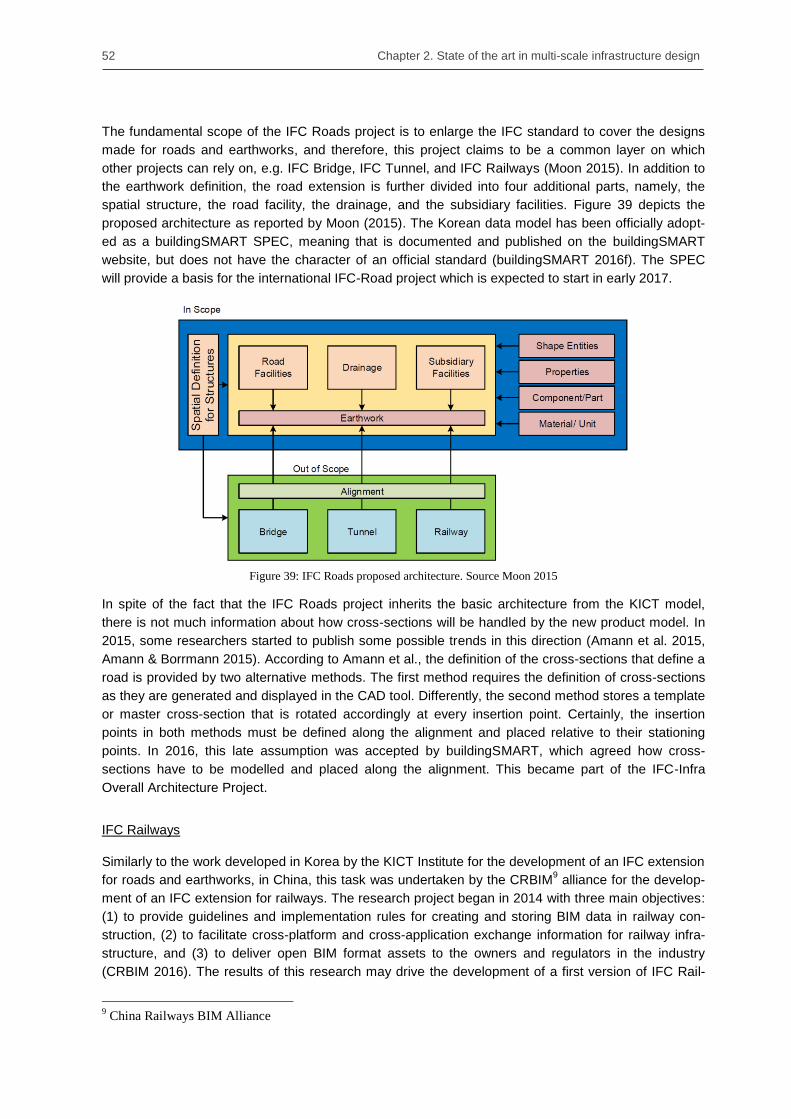
52 Chapter 2. State of the art in multi-scale infrastructure design
The fundamental scope of the IFC Roads project is to enlarge the IFC standard to cover the designs
made for roads and earthworks, and therefore, this project claims to be a common layer on which
other projects can rely on, e.g. IFC Bridge, IFC Tunnel, and IFC Railways (Moon 2015). In addition to
the earthwork definition, the road extension is further divided into four additional parts, namely, the
spatial structure, the road facility, the drainage, and the subsidiary facilities. Figure 39 depicts the
proposed architecture as reported by Moon (2015). The Korean data model has been officially adopt-
ed as a buildingSMART SPEC, meaning that is documented and published on the buildingSMART
website, but does not have the character of an official standard (buildingSMART 2016f). The SPEC
will provide a basis for the international IFC-Road project which is expected to start in early 2017.
Figure 39: IFC Roads proposed architecture. Source Moon 2015
In spite of the fact that the IFC Roads project inherits the basic architecture from the KICT model,
there is not much information about how cross-sections will be handled by the new product model. In
2015, some researchers started to publish some possible trends in this direction (Amann et al. 2015,
Amann & Borrmann 2015). According to Amann et al., the definition of the cross-sections that define a
road is provided by two alternative methods. The first method requires the definition of cross-sections
as they are generated and displayed in the CAD tool. Differently, the second method stores a template
or master cross-section that is rotated accordingly at every insertion point. Certainly, the insertion
points in both methods must be defined along the alignment and placed relative to their stationing
points. In 2016, this late assumption was accepted by buildingSMART, which agreed how cross-
sections have to be modelled and placed along the alignment. This became part of the IFC-Infra
Overall Architecture Project.
IFC Railways
Similarly to the work developed in Korea by the KICT Institute for the development of an IFC extension
for roads and earthworks, in China, this task was undertaken by the CRBIM9 alliance for the develop-
ment of an IFC extension for railways. The research project began in 2014 with three main objectives:
(1) to provide guidelines and implementation rules for creating and storing BIM data in railway con-
struction, (2) to facilitate cross-platform and cross-application exchange information for railway infra-
structure, and (3) to deliver open BIM format assets to the owners and regulators in the industry
(CRBIM 2016). The results of this research may drive the development of a first version of IFC Rail-
9 China Railways BIM Alliance
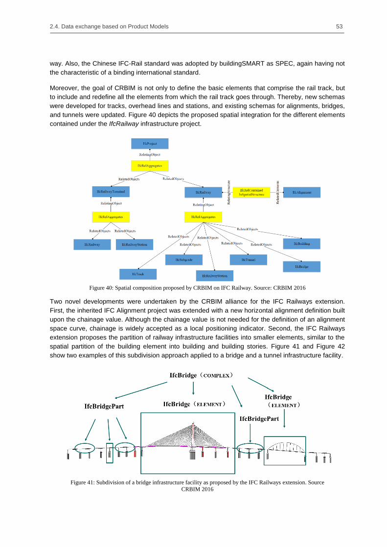
2.4. Data exchange based on Product Models 53
way. Also, the Chinese IFC-Rail standard was adopted by buildingSMART as SPEC, again having not
the characteristic of a binding international standard.
Moreover, the goal of CRBIM is not only to define the basic elements that comprise the rail track, but
to include and redefine all the elements from which the rail track goes through. Thereby, new schemas
were developed for tracks, overhead lines and stations, and existing schemas for alignments, bridges,
and tunnels were updated. Figure 40 depicts the proposed spatial integration for the different elements
contained under the IfcRailway infrastructure project.
Figure 40: Spatial composition proposed by CRBIM on IFC Railway. Source: CRBIM 2016
Two novel developments were undertaken by the CRBIM alliance for the IFC Railways extension.
First, the inherited IFC Alignment project was extended with a new horizontal alignment definition built
upon the chainage value. Although the chainage value is not needed for the definition of an alignment
space curve, chainage is widely accepted as a local positioning indicator. Second, the IFC Railways
extension proposes the partition of railway infrastructure facilities into smaller elements, similar to the
spatial partition of the building element into building and building stories. Figure 41 and Figure 42
show two examples of this subdivision approach applied to a bridge and a tunnel infrastructure facility.
Figure 41: Subdivision of a bridge infrastructure facility as proposed by the IFC Railways extension. Source
CRBIM 2016

54 Chapter 2. State of the art in multi-scale infrastructure design
Differently to the approach followed by other infrastructure groups, where the proposed extension
concentrates on the definition of new semantic entities, the CRBIM alliance proposes a combination of
static and dynamic definitions (CRBIM 2015). For the static definition of generic IFC infrastructure
modules, the CRBIM proposal relies on the buildingSMART guidelines of object-oriented inheritance,
and hierarchical entity definition. Otherwise, elements that are considered specific to a country or area
of influence, are defined following a dynamic definition.
Figure 42: Subdivision of a tunnel infrastructure facility as proposed by the IFC Railways extension. Source
CRBIM 2016
2.4.5. Parametric extension for IFC
Although building models are widely used to exchange information among architects, designers and
engineers, the geometrical representation techniques these models implement hardly support the
dynamic processes of the early design phases. In particular, architects are frequently unwilling to start
their projects using BIM approaches due to the limited modeling capabilities BIM software implement,
and rather prefer to rely on more generic modeling and drawing techniques (Boeykens 2012).
Differently, parametric modeling techniques generate flexible geometric representations that can be
easily altered by the modification of its primary operations and parameters. An example of these
modeling limitations and how they can be overcome with parametric geometry was reported by Ji et al.
(2012). In their work, Ji et al. show that the design of bridge‘s superstructures with varying profiles
along the alignment can be effortlessly defined using sketch-based parametric cross-sections. Fur-
thermore, Ji et al. prove that the geometry generated by such methodology can be directly applied as
an input model for structural analysis. Katz (2008) gave two examples of structural simulations for
bridges where parametric geometry was providing the exact geometry without the need of a re-
modeling stage, namely, the precise calculation of centrifugal forces, and the analysis of effects due to
post-stressing tendons.
However, the relevance of parametric modeling was acknowledged long time before for mechanical
and aerospace industries. Moreover, the ISO organization – responsible of the development of the
STEP standard – established a working group within the TC-184 with the aim of creating a parametric
model schema (Pratt et al. 2005). The achievements of this group were published under the ISO
10303 Part 108 ―Parameterization and constraints for explicit geometric product models‖ in 2005 (ISO
2005b) and its main characteristics previously discussed in Section 2.4.2
Due to the large amount of constraints the schema defines and the complexity of its implementation in
commercial software, the exchange functionalities were seldom implemented by software companies
(Ji et al. 2012). To partially overcome the implementation issues large sets of constraints with complex
relations between objects introduced, Ji et al. (2011) presented a reduced definition of the schema
limited to the most basic constraint and dimension types. Figure 43 depicts their reduced schema for
parametric sketches. The presented schema is divided into three major parts: first, box no. 1 contains

2.4. Data exchange based on Product Models 55
the definition of eight geometrical constraints, which relates the geometric objects defined in box no. 2;
finally, in box no. 3 the schema defines five different dimensional constraints.
Important to mention is that neither the STEP Part 108 nor the reduction done by Ji et al. takes into
consideration the construction history of the parametric model. However, as already discussed in
section 2.4.2, the STEP standard contains two other Parts, 55 and 111, that specifically address these
procedural constructions.
Figure 43: UML diagram of the reduced parametric sketch presented by Ji et al. 2011. On the box no. 1 the
geometric constraints are displayed; on the box no. 2 the geometry objects; and on the box no. 3 the dimen-
sional constraints. Source: Modified picture from Ji et al. 2011
IFC Parametrics
The strength of parametric geometry is not only a desirable property of infrastructure modeling, but
also a concept that can be introduced in products defined by catalog, such as doors and windows.
This potential was also identified by buildingSMART that in the early 2010s organized a working group
in order to develop a first version of IFC Parametrics. Although the result of this project was never
integrated in any official IFC version, the proposed extension was named PA1-Parametric and hosted
on the website of buildingSMART waiting for future developments (buildingSMART 2016c).
In particular, for the new parametric model the working group made use of the developments achieved
by Ji et al. in the field of parametric bridge design and implemented their developments in an extended
parametric version of the IFC-Bridge. Hence, the proposed product model extended the bridge profile

56 Chapter 2. State of the art in multi-scale infrastructure design
definition inheriting a new entity ParametricSketch10
from the regular profile definition entity ProfileDef.
At the same time ParametricSketch defined three lists classifying the three main components of the
parametric sketch, namely, the geometry, and the geometric and dimensional constraints. These two
last groups of elements were defined as optional, due to the fact that a sketch can be partially defined
without dimensions and without geometric constraints.
Figures 43, 44, and 45 depict by means of EXPRESS-G diagrams the different data structures of
parametric sketches, geometric constraints and dimensional constraints, in this order.
Figure 44: EXPRESS-G diagram of the basic structure of a parametric sketch. The blue box defines the ex-
tension over IFC-Bridge containing the sketch geometric elements (points, lines and arcs) and the two lists of
dimensional and geometric constraints. Source: Ji et al. 2012
Figure 45: EXPRESS-G diagram of the geometric constraint data structure. Source: Ji et al. 2012
10
For sake of simplicity the front term Ifc will be omitted.

2.4. Data exchange based on Product Models 57
Figure 46: EXPRESS-G diagram of the dimensional constraint data structure. Source: Ji et al. 2012
Another novel improvement introduced by the parametric extension was the definition of flexible di-
mensions by means of parameters. In particular, each dimensional constraint defines a single parame-
ter whose numerical value is assigned or calculated from an algebraic formula.
Figure 47: EXPRESS-G diagram of the parameter structure. Both constants and formulas are associated to its
evaluated numerical value. Source: Ji et al. 2012
In order to describe more complex arithmetical formulas built upon combinations of fixed values and
algebraic relations, the proposed extension made use of the composite design pattern, widely extend-
ed in software engineering (Gamma et al. 1995). The basic functionality of this pattern is based on
organizing recursively part-whole hierarchies in a tree structure. Consequently, each parametric for-
mula defines an operator (e.g., ADD, SUBTRACTION, MULTIPLY or DIVIDE) and two elements or
operands that can be either defined as parametric constants or further decomposed into additional
parametric formula objects.
Figure 48: Example of a parameter evaluated by an algebraic formula. In this example the inner diameter of a
tunnel is calculated based on the value of the outer diameter subtracted from the result of doubling the thick-
ness of the lining.

58 Chapter 2. State of the art in multi-scale infrastructure design
As example, in Figure 48 an algebraic formula for the calculation of the inner diameter of a tunnel is
shown. Thereby, the inner diameter of a shield tunnel is evaluated by the subtraction from the outer
diameter of the result of a nested algebraic formula parameter, whose value was previously evaluated
by the multiplication of the thickness parameter by two.
2.5. Summary
This chapter first analyzes the evolution of the concept of geographic scale as a representation tool
that enables the abstraction of large information sets. Initially, Geographic Information Systems (GIS)
implemented this fundamental concept to represent cartographic maps on conventional CAD systems.
Due to the variety of scales that GIS systems can manage, several data models appeared to enable
their exchange. One of the most renowned and widely accepted data models is CityGML, which de-
fines five levels of abstraction or detail (LoD). Although CityGML successfully exchanges city and
geographic multi-scale data models, the approach adopted in its development makes CityGML unable
to fulfill the highly dynamic requirements of infrastructure design.
One of the most significant limitations of multi-scale data models is the cross-LoD consistency preser-
vation of its geometry when an object is modified in one specific scale. On the contrary, procedural
representations establish direct dependencies among the different construction elements – also
known as construction operations – that enable the automatic geometry update in a consistent man-
ner. Hence, when one operation is modified by the designer or engineer, its dependent operations are
automatically updated by the parametric CAD system. Another important approach implemented by
parametric systems is the concept of occurrence. Included in the assembly modeling technology,
occurrences are instantiated copies of procedural models that receive a specific position and orienta-
tion in space.
This chapter summarizes with a description of the most employed product models and describes their
role in the current exchange processes in the infrastructure domain. Consequently, the STEP and the
IFC product models are comprehensively described, pointing out their similarities and limitations. Due
to its predominant role in the infrastructure domain, the developments based on the IFC standard are
also analyzed e.g., IFC Alignment, IFC Bridge, and IFC Tunnel. Although there are clear movements
to apply the IFC product model in the infrastructure field, none of the analyzed extensions considers
the multi-scale needs of their design. Therefore, this specific issue is going to be the central point in
the next chapter.

59
Chapter 3. A multi-scale shield tunnel product model
3.1. Overview
The design of large infrastructure facilities is a highly complex task that demands the close collabora-
tion of large engineering teams working on different levels of abstraction. These different levels make
that each engineering team employs the particular tools and data formats specific in its working field,
giving to the efficient integration and exchange of information an additional level of difficulty. One
methodology capable of accomplishing this exchange is based on the use of neutral product models.
However, the main limitation of existing product models, such as STEP or IFC, is the lack of support
they offer for models built upon different levels of abstraction or detail.
A similar problem is present when representing large geographic areas and city models. To address
this problem, GIS systems employ multi-scale data models to reproduce real objects under different
levels of detail. Though GIS models successfully integrate the concept of several levels of detail, these
data models cannot guarantee the consistency among geometric representations when an update or
modification is performed. However, due to the rather static behavior of these models, this weakness
is frequently considered a minor issue.
To fill the existing technological gap, a comprehensive multi-scale product model for shield tunnels is
presented, which addresses the demanding requirements of the design and engineering of large
infrastructure facilities. In order to achieve this goal, this chapter is divided in two main parts. First, a
novel product model for shield tunnels will be reported, which makes extensive use of the spatial
structure concept. The resulting hierarchical structure of entities matches the demands of conceptual
and detailing design stages, placing the physical objects only after their space definition is known.
Second, the previously defined spaces will be assigned to different levels of detail. Specifically, in the
presented concept, the multi-scale definition is part of the semantic model, only enabling access to
specific entities from a particular level of detail.
An additional aim defined at the time of developing the presented product model was to establish the
semantic definition in a way that may be related with any of the current IFC geometrical technologies.
Due to the strict separation that the standard establishes between semantics and geometry, a novel
product model was developed independently of the final modeling strategy adopted in its later imple-
mentation. In summary, this chapter presents a novel multi-scale shield tunnel product model that
covers in a comprehensive way the semantics of a shield tunnel, that is downwards compatible with
existing IFC implementations, and that can be combined with any conventional modeling strategy.

60 Chapter 3. A multi-scale shield tunnel product model
3.2. A novel product model for shield tunnels
3.2.1. Tunnel space structure
The point of departure in the development of a novel product model for shield tunnels was the current
IFC-Tunnel proposal from Yabuki (2007, 2009 and 2013). In particular, the developed product model
addresses the two main limitations reported on the Yabuki model. First, the new model describes in a
comprehensive way not only the outside lining of the tunnel, but also the equipment and installations
located in its interior. Second, the amount of entities needed for its description have been condensed
to its minimal expression by the use of enumerators, reducing the amount of resources required for its
implementation.
During the product model‘s development, a principle of minimal intervention was followed, i.e., only a
minimal number of the existing IFC entities was modified and only a minimal number of new entities
were defined. This strategy has its clearest exponent in the tunnel spatial structure. Thereby, only two
new entities were defined to contain the complete tunnel infrastructure, namely, the Tunnel11
and
TunnelPart. Similar to the building spatial structure where several Buildings can be defined in a Site
and several BuildingStoreys can be contained in a Building, in the novel tunnel spatial structure,
several Tunnels can be defined in a Site and several sections or TunnelParts can be chained in a
Tunnel. Figure 49 shows a comparison of these two spatial structures.
Figure 49: (left) Building spatial structure as defined in the IFC standard; (right) Developed shield tunnel spa-
tial structure, which enables the definition of several tunnels divided into several sections or tunnel parts. The
new tunnel entities are depicted in white.
The Tunnel entity is used to represent each of the tunnels contained in the subway facility. On the
specific case of shield tunnels, which usually are designed in a twin-tunnel configuration, each tunnel
is represented by one tunnel instance. In a similar way, the TunnelPart entity represents each of the
sections in which the tunnel is subdivided. Typically, these sections are logical subdivisions mainly
based on design or construction requirements. The term TunnelPart was chosen in favor of Tun-
nelSection first to avoid confusions with the term cross-section frequently used in subway design and
second, to unify the concept with the term as defined by CityGML v2.0.
Although the proposed solution based on tunnels and tunnel-parts is a particular development for the
updated version of IFC-Tunnel, the developed methodology of minimal intervention and subdivision of
the product model into smaller sections is general and applicable to a larger range of infrastructure
facility types.
11
From this point, the prefix Ifc is going to be omitted for simplicity.

3.2. A novel product model for shield tunnels 61
3.2.2. Tunnel refinement – Structure of space and physical objects
The basic tunnel spatial structure is exclusively described by the entities Tunnel and TunnelPart.
These two general entities describe the simplest semantic subdivision independently of the tunnel
cross-section or construction method selected. Differently, the subsequent tunnel space refinement is
strongly related to the cross-section and topology of the tunnel, i.e., the spaces defined in a one-way
shield tunnel will greatly differ from a two-way cut-and-cover tunnel.
A recurrent problem in the spatial refinement of semantic models is the granularity employed in the
description of the different spaces. Here, a compromise must be taken that does not reduce the num-
ber of spaces to a general, all-inclusive structure, but also avoiding the definition of a space volume for
every physical object. As an example, in the presented approach only one single service space is
defined along the tunnel, while for the same physical objects the PAS 1192-2 specification generates
three subspaces; the communication, signaling, and ohle volumes (BSI 2013).
Figure 50: A tunnel cross-section depicting the individual spaces (left) and physical elements (right) of the
proposed shield tunnel product model.
Keeping this compromise in mind, the proposed shield tunnel product model describes six main tunnel
spaces that together with three gathering spaces and two alignment objects complete the semantic
refinement of the shield tunnel product model. In particular, the two alignment objects are sequential
additions of space curves with the only aim of providing extra information to the engineering process.
Thus, the two alignment objects are:
The alignment object – The tunnel alignment represents the curve midway between the two
rails and is usually constructed by the superposition of two 2D curve representations known as
horizontal and vertical alignments. Although in the presented product model, these space
curves are directly related to the alignment object, a further semantic detailing is possible. So,
the integration of the IFC-Alignment contained in the future IFC 5 standard is the next logical
step (Amann et al. 2014a, 2014b).
The tunnel axis object – The tunnel axis object represents the theoretical path that shapes
the lining of the shield tunnel. During the design, engineers employ this curve to calculate the
successive placement and rotation of individual rings. Similar to the alignment object, the tun-
nel axis is not further detailed and its representation is based on simple spatial curves.

62 Chapter 3. A multi-scale shield tunnel product model
As previously mentioned, additional to the alignment objects, three gathering spaces and six tunnel
specific spaces have been defined. Figure 50 depicts, on the left-hand side, the mentioned tunnel
spaces. More in detail, the developed spaces are the following:
Annular Gap Space – The annular gap is the space that remains between the resulting cavity
created by the Tunnel Boring Machine (TBM) and the inserted ring. This gap is usually filled
with injected concrete in order to increase the structural stability of the tunnel (Maidl et al.
1996, 2008, Guglielmetti et al. 2008).
Ring Space – As previously mentioned, the shield tunnel construction methodology employs
rings to generate the lining of the tunnel. These rings integrate several pre-cast segments that
are assembled as the construction of the tunnel progresses. Each instance of this space ob-
ject contains the complete definition of one individual ring.
Floor Space – The floor space acts as a placeholder for all the elements that are constructed
under the track, e.g., cable ducts, sewage systems, and drainage pits. In particular, the bottom
part of this space is adapted to the ring‘s geometry and therefore this space has no continuity
outside of the tunnel (Coats and Walter, 1999).
Track Space – The track space defines the main properties, location, and maximal size of the
track system. As the track configuration, usually ballast-track or slab-track, runs stable along
several sections of the subway infrastructure, this space can have continuity outside of the
tunnel, i.e., the same track space definition can be used in a tunnel and its connected subway
stations.
Service Space – The service space contains the active systems that enable the operation of
the infrastructure, e.g., signaling, illumination, and traction system. Though some of these sys-
tems are also placed on the subway station, the definition of the service space is exclusive to
the inside of the tunnel and this space has no continuity outside of the tunnel.
Clearance Space – The clearance space, also known as structure gauge, is the security zone
reserved for the travelling train. This space, defined by international standards, is empty and
has no physical objects attached to it. Although the space reserved for the gauge can slightly
diverge from tunnels to stations, in the proposed product model the definition of the clearance
space is constant and therefore can be applied outside of the tunnel.
Finally, the spatial structure is completed by the application of three gathering spaces. At the top, the
FullTunnelSpace assembles the entire instantiated objects in a unique space object that is placed
directly beneath the TunnelPart and parallel to the alignment objects. Situated below, the LiningSpace
and the InteriorSpace collect the ring spaces that outline the tunnel‘s lining and the specific spaces
that subdivide the tunnel‘s interior respectively. Figure 51 depicts an instantiated spatial structure
diagram where the different detailing spaces are represented.
To represent unambiguously the refinement structure of spaces, the new entity IsRefinedBy has been
introduced. This class, which is directly inherited from the Aggregation relationship, enables the clear
representation of the hierarchical relations among the gathering and the specific spaces. In addition,
and just for consistency reasons, the two alignment objects have been also related to the tunnel space
object with the IsRefinedBy aggregation relationship.

3.2. A novel product model for shield tunnels 63
Figure 51: Instantiated space structure diagram containing the different detailing space objects. The black
rhomboids represent the aggregation relationships IsRefinedBy.
The detailing of the product model is completed by the definition of seven physical objects, namely,
the ring segment, cable duct, drainage, track bed concrete, track bed rails, traffic light, and walkway.
These objects, which are instances of the two newly defined RingSegment and TunnelInstallation
classes, are logically placed on the element containment structure. As a direct consequence of this
separate location, instead of the aggregation relation implemented among the space objects in the
spatial structure, the relation ContainedInSpatialStructure is used to connect spaces and physical
objects.
Unlike the Yabuki approach, where every ring segment type is described by a dedicated entity, the
new defined RingSegment class is unique and can be applied to all type of segments by introducing
the right description to its instantiated properties. In a different way, the TunnelInstallation class is
instantiated with the value of an enumerator that contains the attribute of the physical object. Although
the number of items on the current version of the product model is limited, the description based on
enumeration variables enables the flexible extension of the presented proposal with more detailed
references.
In addition to the identification of the physical objects that are placed in the interior of the tunnel, a
thematic sorting of the different objects has been made. Thus, physical objects that are not related to a
specific space can be neither instantiated nor related. In particular, the physical objects are organized
as follows: the RingSegment is related to the RingSpace; the CableDuct and Drainage are related to
the FloorSpace; the TrackBedConcrete and TrackBedRails are related to the TrackSpace; and finally
the TrafficLight and Walkway are related to the ServiceSpace. Figure 50 shows, on the right-hand
side, the different physical objects as they are located in a tunnel cross-section, while Figure 53 de-
picts the relations among the physical objects and their tunnel spaces.
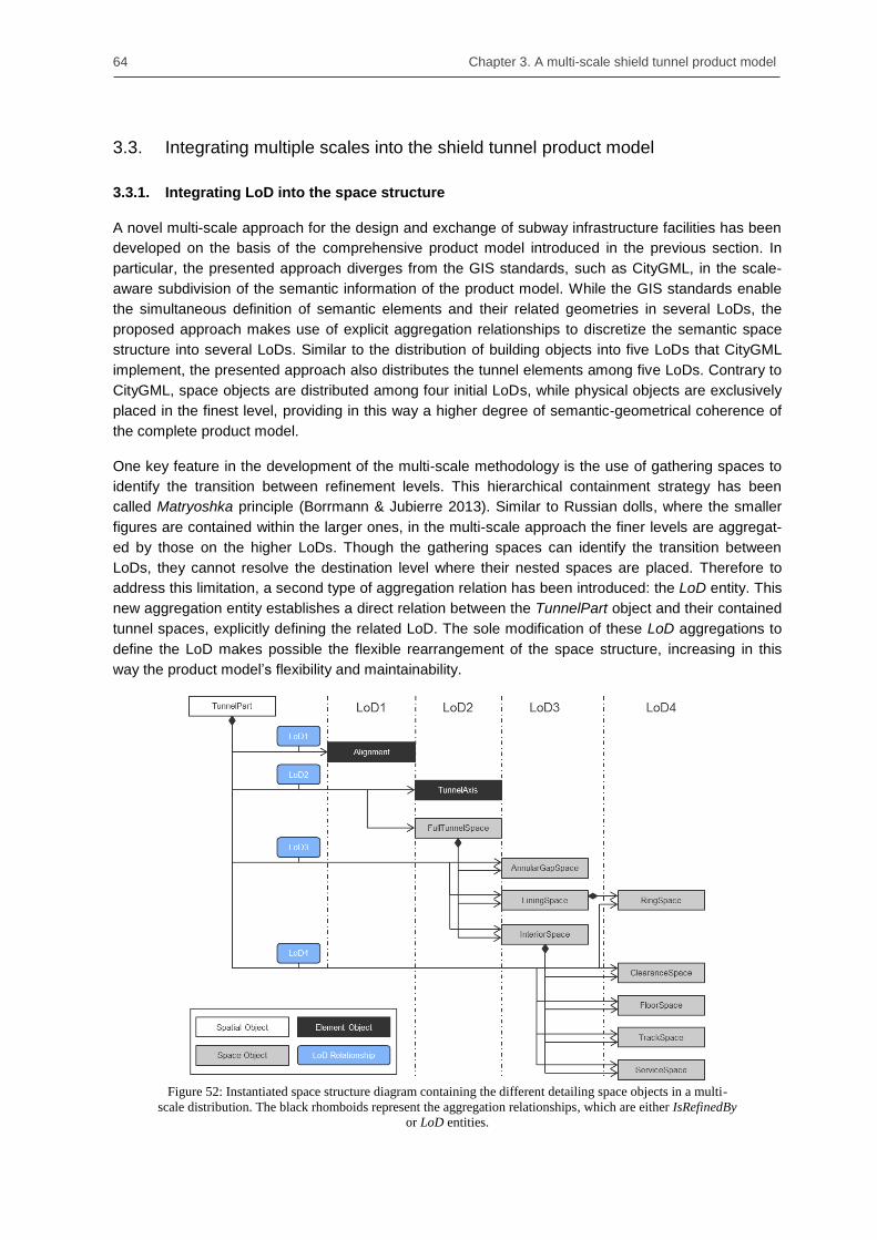
64 Chapter 3. A multi-scale shield tunnel product model
3.3. Integrating multiple scales into the shield tunnel product model
3.3.1. Integrating LoD into the space structure
A novel multi-scale approach for the design and exchange of subway infrastructure facilities has been
developed on the basis of the comprehensive product model introduced in the previous section. In
particular, the presented approach diverges from the GIS standards, such as CityGML, in the scale-
aware subdivision of the semantic information of the product model. While the GIS standards enable
the simultaneous definition of semantic elements and their related geometries in several LoDs, the
proposed approach makes use of explicit aggregation relationships to discretize the semantic space
structure into several LoDs. Similar to the distribution of building objects into five LoDs that CityGML
implement, the presented approach also distributes the tunnel elements among five LoDs. Contrary to
CityGML, space objects are distributed among four initial LoDs, while physical objects are exclusively
placed in the finest level, providing in this way a higher degree of semantic-geometrical coherence of
the complete product model.
One key feature in the development of the multi-scale methodology is the use of gathering spaces to
identify the transition between refinement levels. This hierarchical containment strategy has been
called Matryoshka principle (Borrmann & Jubierre 2013). Similar to Russian dolls, where the smaller
figures are contained within the larger ones, in the multi-scale approach the finer levels are aggregat-
ed by those on the higher LoDs. Though the gathering spaces can identify the transition between
LoDs, they cannot resolve the destination level where their nested spaces are placed. Therefore to
address this limitation, a second type of aggregation relation has been introduced: the LoD entity. This
new aggregation entity establishes a direct relation between the TunnelPart object and their contained
tunnel spaces, explicitly defining the related LoD. The sole modification of these LoD aggregations to
define the LoD makes possible the flexible rearrangement of the space structure, increasing in this
way the product model‘s flexibility and maintainability.
Figure 52: Instantiated space structure diagram containing the different detailing space objects in a multi-
scale distribution. The black rhomboids represent the aggregation relationships, which are either IsRefinedBy
or LoD entities.

3.3. Integrating multiple scales into the shield tunnel product model 65
The proposed tunnel spatial structure has been discretized into the four coarser levels. In LoD1, only
the alignment of the shield tunnel is represented, whiles the tunnel axis and the first gathering space,
the so-called FullTunnelSpace, is introduced in LoD2. The subsequent nested spaces are distributed
following the principle ―one step, one LoD―, which means that directly related space objects are placed
just one LoD apart. Consequently, the AnnularGapSpace and the two remaining gathering spaces are
placed in LoD3 and their nested spaces in LoD4. Figure 52 depicts the proposed distribution. It is
important to mention that the nested spaces preserve their IsRefinedBy relation with the gathering
space, making them reachable by two ways, i.e., via LoD or via IsRefinedBy.
3.3.2. Integrating LoD with physical objects
During the detailing process, the specific spaces are populated with physical objects. Though the
spaces are distributed across different LoD in direct relation with the location of its parent gathering
space, the physical objects are placed essentially in the finest LoD, the LoD5. Similar to the double
aggregation dependency that relates the alignment and space objects, the physical objects are related
to their specific space and to the TunnelPart object. However, while the LoD aggregation is equally
applied to physical objects placed on LoD5, the relation IsRefinedBy is not used among spaces and
physical objects. The relation ContainedInSpatialStructure is applied instead. This entity is the IFC
regular connector between elements in the spatial structure and in the element containment, and
makes the proposed product model downwards compatible with the current IFC standard. Figure 53
depicts the relations stablished among the physical objects placed on the finest LoD and the tunnel
spaces. In addition, Figure 54 shows in a 3D view, the distribution of the different spaces and physical
objects across the different LoD.
Figure 53: Instantiated LoD4 of the space structure and the physical objects contained in LoD5. The physical
objects are related to both the LoD and the ContainedInSpatialStructure entities.

66 Chapter 3. A multi-scale shield tunnel product model
Figure 54: A 3D illustrative representation of the spaces and physical objects located across the LoDs. The
alignment object contained in LoD1 is not represented.
As already mentioned in this chapter, the development of the new multi-scale shield tunnel product
model has been conducted under the principle of minimal intervention. This principle is not a novel
paradigm, but both a widely adopted approach in object-oriented programming and a recommendation
described in the general guidelines of the IFC standard. In order to give a complete overview of the
developed extension, Figure 55 depicts a UML diagram where the three major conceptual extensions
are represented.
Figure 55: UML class diagram depicting the three areas where the IFC standard was extended. In blue are the
two new aggregation relationships IsRefinedBy and LoD. In grey are the space entities related to the space
structure. Finally, in black are the physical element entities.
First, on the top, the two new aggregation relationships IsRefinedBy and LoD are represented. These
entities are inherited directly from the Aggregation class and enable the scale-aware subdivision of the
semantic model. Later, on the bottom left part of the UML diagram, the classes of the spatial structure
are depicted. In the first row, the general Tunnel and TunnelPart are represented, while, on the sec-
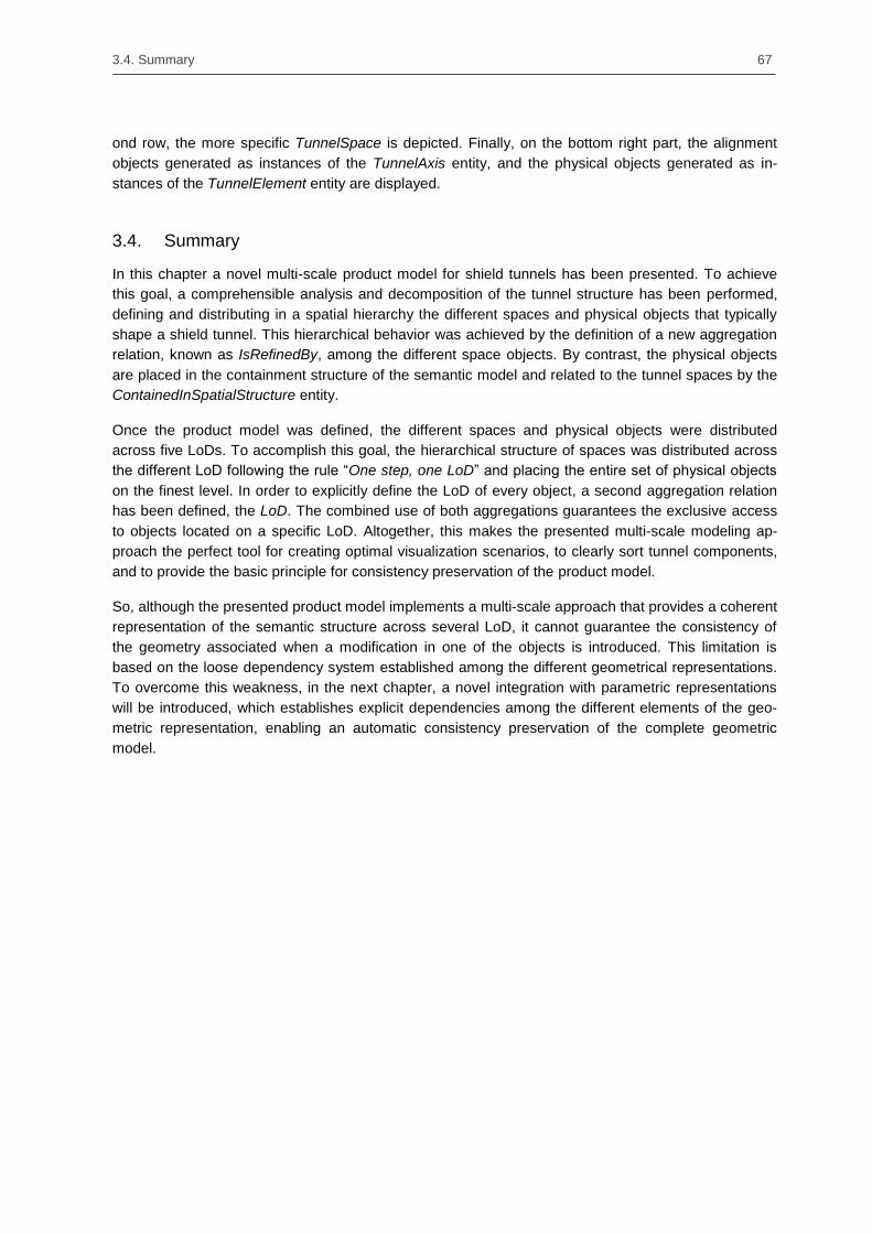
3.4. Summary 67
ond row, the more specific TunnelSpace is depicted. Finally, on the bottom right part, the alignment
objects generated as instances of the TunnelAxis entity, and the physical objects generated as in-
stances of the TunnelElement entity are displayed.
3.4. Summary
In this chapter a novel multi-scale product model for shield tunnels has been presented. To achieve
this goal, a comprehensible analysis and decomposition of the tunnel structure has been performed,
defining and distributing in a spatial hierarchy the different spaces and physical objects that typically
shape a shield tunnel. This hierarchical behavior was achieved by the definition of a new aggregation
relation, known as IsRefinedBy, among the different space objects. By contrast, the physical objects
are placed in the containment structure of the semantic model and related to the tunnel spaces by the
ContainedInSpatialStructure entity.
Once the product model was defined, the different spaces and physical objects were distributed
across five LoDs. To accomplish this goal, the hierarchical structure of spaces was distributed across
the different LoD following the rule ―One step, one LoD‖ and placing the entire set of physical objects
on the finest level. In order to explicitly define the LoD of every object, a second aggregation relation
has been defined, the LoD. The combined use of both aggregations guarantees the exclusive access
to objects located on a specific LoD. Altogether, this makes the presented multi-scale modeling ap-
proach the perfect tool for creating optimal visualization scenarios, to clearly sort tunnel components,
and to provide the basic principle for consistency preservation of the product model.
So, although the presented product model implements a multi-scale approach that provides a coherent
representation of the semantic structure across several LoD, it cannot guarantee the consistency of
the geometry associated when a modification in one of the objects is introduced. This limitation is
based on the loose dependency system established among the different geometrical representations.
To overcome this weakness, in the next chapter, a novel integration with parametric representations
will be introduced, which establishes explicit dependencies among the different elements of the geo-
metric representation, enabling an automatic consistency preservation of the complete geometric
model.


69
Chapter 4. Consistency preservation methods for multi-scale procedural geometry representations
4.1. Overview
The previous chapter introduced a comprehensive multi-scale product model that provides a coherent
representation of the semantic structure across several LoD. Although this novel approach guarantees
a sound distribution of semantic elements up to a defined LoD, their shape representation capabilities
are limited to conventional geometric structures, i.e. explicit B-Rep representations or implicit repre-
sentations based on closed profiles, sweeps, and Boolean operations. These structures do not hold
any relation or dependency among them, but a single association with the corresponding semantic
object. This loose coupling system makes current product models very sensitive to changes in coarser
LoDs, which can easily generate inconsistencies in the geometric representation of the product model.
This issue is known as the cross-LoD consistency problem, i.e. the geometry in more detailed LoD has
to remain consistent with that of the coarser LoD when a modification in a coarser LoD is performed
(Borrmann & Jubierre 2013).
Another source of inconsistency in the geometric representation of product models is caused by the
subdivision of the model into several partitions or submodels. Based on diverse criteria such as budget
disposal, topological distribution, and design optimization, the developed shield-tunnel product model
enable the subdivision of large infrastructure projects into several parts, so each part contains a quasi-
identical semantic definition associated with a greatly divergent geometric representation. This makes
that a small update in a semantic element on a submodel can influence several geometric elements
located in several submodels. One example of this behavior can be easily illustrated on the alignment
of an infrastructure facility. Thus, the update of an alignment element affects not only its geometry but
also the geometry of its related submodels. This problem has been called the cross-submodel con-
sistency problem (Jubierre & Borrmann, 2013).
Both consistency problems - the cross-LoD and the cross-submodel - are originally caused by the fact
that dependencies between geometric elements cannot be defined when using conventional shape
representations. On the contrary, procedural geometries define explicit dependencies among their
construction operations that guarantee a consistent update when one of these operations is modified.
Moreover, parametric sketches allow designers and engineers to create flexible designs that can be
altered by updating a parameter or modifying the defined constraints (Joan-Arinyo & Soto 1997).
An additional difficulty designers and engineers have to tackle during the design of a large infrastruc-
ture facility is the interpretation of engineering guidelines, codes, and national standards. Moreover,
the implementation of these engineering rules in a set of construction operations is not a simple or
direct task. Thus, designers and engineers must be aware of the additional dependency relations

70 Chapter 4. Consistency preservation methods for multi-scale procedural geometry representations
needed to achieve the desired consistency preservation and implement them manually in a process
that is labor-intensive and error-prone.
To support designers and engineers appropriately, this chapter presents in Section 4.3 a novel usage
of procedural geometric models for the design of large infrastructure facilities. To this end, an exten-
sion of the basic procedural dependency approach is presented, which enables procedural models to
preserve its consistency through several LoDs. In addition, to clearly represent the combination of
procedural and newly-defined dependencies, in Section 4.2, a novel notation based on dependency
diagrams is reported.
To address the cross-submodel consistency problem, Section 4.4 presents a new set of dependencies
that relate equivalent construction operations on consecutive submodels. Moreover, this section also
introduces the integration of distinct infrastructure elements as a special type of submodels that are
located at specific stationing points, e.g., rescue shafts, connection tunnels, and tunnel chambers.
Finally, this chapter presents in Section 4.5, a novel methodology that assists designers and engineers
in the generation of geometry and required dependencies at the time of implementing complex engi-
neering rules. This methodology encapsulates the underlying generation knowledge in discrete units
named logic models that convert the abstract information into a corresponding parametric geometry
model.
4.2. Integration concept and dependency graph notation
4.2.1. Integration of procedural representations into product models
Current product models, such as STEP or IFC, establish direct relations between semantic elements
and geometric objects. These relations enable a comprehensive semantic-geometric description of the
model. However as described previously, the provided geometric representations do not support the
definition of dependencies between the shape representation of individual objects, which in turn per-
mits the existence of geometric inconsistencies. To address this limitation, this thesis proposes the
use of procedural representations to introduce a new level of control that prevents geometric incon-
sistencies from appearing. In the following sections the conceptual integration of procedural models as
a novel geometric representation is analyzed, focusing on the handling of space objects and physical
objects.
Integrating procedural space objects
Chapter 3 presented a new product model that distributes several space objects throughout four LoDs.
These space objects act as containers of physical elements located in LoD5. Current product models,
such as STEP or IFC, base their shape representation on conventional explicit geometries, whose
loose dependency systems make the geometric shape representation highly sensitive to modifications
and susceptible to inconsistencies.
Introducing procedural models as a novel geometric shape representation implies that the current
relation system between semantics and geometry is no longer valid. In contrast to the explicit geome-
tries that conventional CAD systems handle, procedural models store a sorted list of construction
operations that allow parametric systems to rebuild the final geometry. This approach has two direct
consequences on conventional semantic-geometry relations: (1) semantic elements no longer have a
direct relation with the resulting geometry, but with a construction operation that must be interpreted by

4.2. Integration concept and dependency graph notation 71
the parametric CAD system; and (2) not all the operations on the construction history have a direct
relation with a semantic element, e.g. one semantic object points to the volume created by an extru-
sion operation, but not to the sketch that defines its cross-section.
In consequence, a new methodology is defined to regulate how semantics and geometry have to be
related. Based on a single dependency rule, semantic spaces only relate one construction operation at
a time. In case the space object is defined by a collection of procedural operations, its dependency will
be established with the last defining operation. However, this basic rule can be relaxed depending on
the type of semantic object that is related. Following, the three main types of semantic spaces defined
in the previous chapter are analyzed and their relaxation approach described:
Alignment objects are frequently modelled by a single 3D curve contained in a construction
operation. Hence, alignment objects establish a one-to-one relation with its defining construc-
tion operation.
Gathering space objects are applied to collect several semantic-related space objects.
Since gathering objects do not relate any geometry, they do not define any relation to any
construction operation.
Tunnel space objects are usually modelled by a subset of construction operations. Thus, the
relation is exclusively defined between the space object and the last construction operation of
the subset.
Figure 56: Portion of a tunnel product model, which represents the relations established between semantic
space objects and procedural construction operations. (In this figure, the arrows between construction opera-
tions only represent their sequence on the construction history)
An example of this new relation system is depicted in Figure 56. In the provided example, a small
portion of a tunnel product model is shown. The semantic model is represented by an alignment
object, a gathering, and tunnel space objects, while the geometry is represented by four construction
operations. The TunnelAxis object is directly related to the first construction operation, which describes
the alignment curve with a single spline 3D operation. In a different way, the AnnularGapSpace object
points only to the last construction operation. Despite this, the space object needs the complete set of
operations to be fully defined. Finally, as the FullTunnelSpace is defined to collect semantic-related
space objects, it does not have any relation to any construction operation.
72 Chapter 4. Consistency preservation methods for multi-scale procedural geometry representations
Integrating procedural physical objects
The integration of procedural representations into multi-scale product models has several essential
benefits such as, consistency preservation, division of the complete project into smaller partitions, and
the integration of design intent. However, the use of a single procedural model that describes the
complete multi-scale system involves at least three serious limitations:
Large infrastructure facilities frequently use large amount of standardized objects such as,
traffic lights, ventilation systems, and sewage conductions. Due to the limitations of procedural
models to define dependency relations between imported neutral geometries and the con-
struction operations, designers and engineers are often forced to re-model such geometries
inside the parametric system, an extremely time-consuming process.
Once the design is finished and physical objects must be exchanged with other stakeholders,
the task of isolating the list of construction operations that are responsible for the definition of
each physical object becomes extremely difficult and highly time-consuming.
Although there are no scientific studies that relate the number of construction operations with
its processing time, experience shows that this relation can be approximated by a linear rela-
tion. Therefore, the more detailed the model, the lower its performance.
These three major limitations arise mainly for modeling LoD5. First, standardized parts are usually
exchanged by means of explicit geometry, which cannot be easily handled by procedural geometries.
Secondly, the explosion in the number of construction operations needed for the design of every
physical object strongly reduces its performance and consequently the acceptance of procedural
geometries. Finally, once the geometric model is completed, the selection and exchange of parts of
the model becomes a highly time-consuming task.
However, these limitations can be easily overcome by the use of the assembly approach. Assemblies
divide the complete geometry into smaller portions called parts. These parts can be either procedural
or neutral explicit geometries. Procedural parts contain only a limited number of construction opera-
tions needed to describe distinct elements, so their performance is not affected. Finally, parts are
stored on independent files, which can be easily exchanged among stakeholders.
Due to the clear benefits assemblies introduce on the infrastructure design, this thesis presents a dual-
design concept based on procedural and assembly geometries. On the one side, procedural models
are applied to the design of infrastructures with coarse LoD. Thereby, the complete tunnel space
design is performed by means of a single procedural geometry named space model. This model
encapsulates all the construction operations defined by the different parts in which the infrastructure is
divided, thereby realizing the demanded unity and consistency.
On the other side, the detailing required for LoD5 is achieved by the combination of assembly, proce-
dural and explicit geometries. In particular, each tunnel space object generates a new assembly model
that contains as many independent models as physical objects defined in its semantic definition. Such
independent models are defined as a procedural or neutral explicit geometry. One example of this
strategy is depicted in Figure 19 in Section 2.2.3 where a simple tunnel model – represented by the
lining space and two nested ring spaces – is modeled by three assemblies, namely, one for the lining
space and two for the two ring spaces. In turn, each ring assembly contains as many independent
geometrical objects as segments defined by the ring.

4.2. Integration concept and dependency graph notation 73
Figure 57 – Floor space represented in LoD5, where the dual approach is implemented. Hence, space objects
are represented by assemblies, and physical objects by procedural (grey) and explicit (orange) geometries.
Another example of this dual strategy is depicted in Figure 57. This time a floor space is detailed by
the combination of one procedural model for the concrete floor, and three neutral explicit geometries
for the cable duct cover and drainage system. This approach is clearly advantageous because tunnel
engineers only need to model the concrete floor while just having to add to the assembly the neutral
explicit geometries created by an external provider.
4.2.2. Dependency graph notation in parametric modeling
Dependency graph notation in procedural models
In comparison with conventional CAD systems where the user directly generates the final geometry,
procedural CAD systems maintain the construction steps engineers applied to create the design. This
new approach allows procedural models to consistently update the complete geometry when a modifi-
cation in one construction step is performed. This behavior is possible because the procedural model
establishes dependency relations between construction steps in a transparent manner to the end user.
Construction steps or construction operations, and their dependency relations can be graphical repre-
sented by a dependency diagram. Even more, as the dependencies are oriented, i.e. the dependency
direction cannot be reversed, dependency diagrams fall into the classification of directed acyclic
graphs (DAG) (Hernán & Robins 2006, Foraita et al. 2014). However, the geometric complexity of
multi-scale infrastructure facility models makes insufficient the representation of procedural dependen-
cies based on simple nodes and edges. Consequently, in the scope of this thesis the basic node and
edge elements of DAG representations are extended by a novel procedural notation that is going to be
applied in the remainder of this thesis.
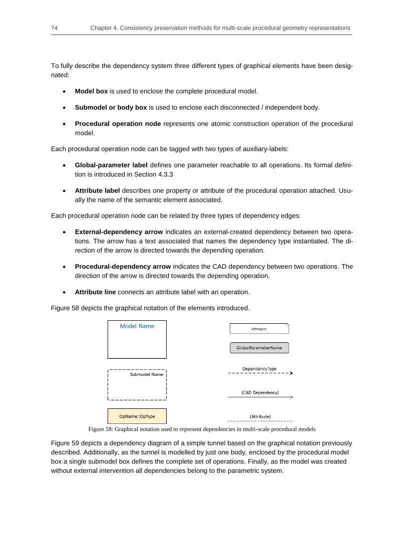
74 Chapter 4. Consistency preservation methods for multi-scale procedural geometry representations
To fully describe the dependency system three different types of graphical elements have been desig-
nated:
Model box is used to enclose the complete procedural model.
Submodel or body box is used to enclose each disconnected / independent body.
Procedural operation node represents one atomic construction operation of the procedural
model.
Each procedural operation node can be tagged with two types of auxiliary-labels:
Global-parameter label defines one parameter reachable to all operations. Its formal defini-
tion is introduced in Section 4.3.3
Attribute label describes one property or attribute of the procedural operation attached. Usu-
ally the name of the semantic element associated.
Each procedural operation node can be related by three types of dependency edges:
External-dependency arrow indicates an external-created dependency between two opera-
tions. The arrow has a text associated that names the dependency type instantiated. The di-
rection of the arrow is directed towards the depending operation.
Procedural-dependency arrow indicates the CAD dependency between two operations. The
direction of the arrow is directed towards the depending operation.
Attribute line connects an attribute label with an operation.
Figure 58 depicts the graphical notation of the elements introduced.
Figure 58: Graphical notation used to represent dependencies in multi-scale procedural models
Figure 59 depicts a dependency diagram of a simple tunnel based on the graphical notation previously
described. Additionally, as the tunnel is modelled by just one body, enclosed by the procedural model
box a single submodel box defines the complete set of operations. Finally, as the model was created
without external intervention all dependencies belong to the parametric system.

4.2. Integration concept and dependency graph notation 75
Figure 59: Example of a dependency diagram of a simple tunnel model using the proposed notation.
Dependency graph notation in assembly models
In the previous section a novel dependency notation is reported that enables the representation of
procedural dependencies in multi-scale models. Though this notation is still valid for the procedural
models contained in an assembly structure, an extension to the notation must be performed to incor-
porate the assembly concept. Consequently, a new graphical element called assembly box has been
included to encompass all the geometric models defined within the assembly. This single notation
element – represented by a blue line box – enhances the previously defined representation capabili-
ties and enables the typical hierarchical representation of the assembly structure.
One aspect that is not covered by this extension is the representation of the spatial dependencies (see
Section 2.3.3) among the procedural models contained in the assembly. This, however, is out of scope
of this notation as such relations cannot be represented by DAG diagrams.
Figure 60: Tunnel project represented by its space and assembly models. On the left the space model repre-
sent the space definition up to LoD4, while on the right the assembly model contains two physical objects
represented by two procedural models. The additional dependencies needed to guarantee the consistency be-
tween construction operations on the space and assembly models are not represented.

76 Chapter 4. Consistency preservation methods for multi-scale procedural geometry representations
To illustrate this new notation element with an example, Figure 60 depicts two dependency diagrams
of a tunnel model. First, on the left-hand side the space model defines, contained in one single proce-
dural model, the concrete floor and track bed space geometries. Differently, on the right-hand side the
assembly model encompass two independent procedural models, where one of them contains the
subset of procedural operations generated in the space model and the construction operations added
during the detailing for LoD5.
4.3. Consistency preservation across different Levels-of-Detail
4.3.1. Overview
The geometrical shape representation in a conventional product model is mainly achieved by using
explicit geometries. Normally, these geometric objects solely have relations with the corresponding
semantic element, leaving the geometric dependencies uncovered. This loose dependency system
can provoke inconsistencies when geometric modifications are performed. To address this weakness,
the previous section has introduced the concept of procedural and assembly geometries applied to
infrastructure design. In particular, procedural geometries define dependencies among its defining
construction operations that allow the parametric CAD system to consistently update the complete
geometry.
The multi-scale design of infrastructure facilities introduces an additional collection of requirements
that product models, based on pure procedural geometries, cannot cover. Therefore, this section first
introduces the adoption of procedural geometries as a tool to guarantee the consistency of multi-scale
product models. Secondly, this section presents a new set of additional procedural dependencies that
fulfil the specific geometric requirements of multi-scale infrastructure product models. Finally, this
section concludes with the introduction of a novel methodology to initialize and relate assembly geom-
etries with the construction operations contained in its defining procedural space model.
4.3.2. Including the concept of Levels-of-Detail in procedural models
The design of a large infrastructure facility follows a top-down approach, i.e., pieces of information are
added to the initial model as the design evolves. This sequential behavior of the design is effectively
covered by multi-scale product models. So additionally to the scale separation, LoD can be used to
determine several stages of design. However, the spread of design content over several LoD without a
comprehensive geometric dependency system, makes multi-scale product models very sensitive to
updates, and therefore to geometric inconsistencies between LoD. To illustrate this sequential design,
Figure 61 depicts an example of a subway infrastructure facility where the same product model is
represented by up to four different LoD or stages of design.

4.3. Consistency preservation across different Levels-of-Detail 77
Figure 61: Multi-scale tunnel model represented up to the fourth LoD. Due to the top-down design approach
and the loose dependency system established among geometric objects, multi-scale product models become
very sensitive to geometric inconsistencies between LoD.
One essential aspect of multi-scale product models is that the semantic model is the unique source of
information required to determine which geometric object is related to each LoD, i.e., no hierarchy in
the geometric model is required. As a consequence, a single dependency system among geometric
objects is sufficient to guarantee the complete geometric consistency of the multi-scale product model.
To achieve this goal, in the previous section, procedural modeling was conceptually introduced. In
contrast to explicit geometries, procedural models only store the construction steps required to rebuild
the outcome geometry. Moreover, procedural geometries have dependencies among its defining
construction operations that allow the parametric CAD system to consistently update the complete
geometry. Based on this approach, semantic elements defined in a distinct LoD only need to set a
reference to the last defining operation in order for the parametric CAD system to identify all the re-
quired construction operations inside the product model.
However, the use of a single procedural model to represent the complete geometry of the product
model involves several limitations, namely, reduction of the loading performance, difficulty in integrat-
ing 3rd
-party explicit geometries, and complexity of isolating and exporting distinct physical objects.
Hence, as already mentioned in Section 4.2.1, a methodology that efficiently addresses these weak-
nesses is the combined use of procedural and assembly modeling techniques. The great benefit of
this solution is that assembly models can be defined as combinations of explicit, procedural and nest-
ed assembly models. This modeling approach, based on the definition of one space model for the
coarser LoD and several assemblies for LoD5, generates a new inconsistency risk due to the exist-
ence of several procedural models that includes the same construction operation and that must remain
consistent. One example of this problem can be found in modeling the concrete floor. Initially defined
in LoD4, its cross-section is defined by a construction operation in the procedural space model. The
same operation is later applied to start the detailing of the concrete floor model on the LoD5 in a
separate procedural model. Consequently, to avoid inconsistencies, every time the construction opera-
tion of the space model is modified, its counterpart on the assembly model must also be updated.
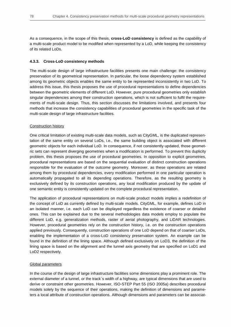
78 Chapter 4. Consistency preservation methods for multi-scale procedural geometry representations
As a consequence, in the scope of this thesis, cross-LoD consistency is defined as the capability of
a multi-scale product model to be modified when represented by a LoD, while keeping the consistency
of its related LoDs.
4.3.3. Cross-LoD consistency methods
The multi-scale design of large infrastructure facilities presents one main challenge: the consistency
preservation of its geometrical representation. In particular, the loose dependency system established
among its geometric objects enables the same entity to be represented inconsistently in two LoD. To
address this issue, this thesis proposes the use of procedural representations to define dependencies
between the geometric elements of different LoD. However, pure procedural geometries only establish
singular dependencies among their construction operations, which is not sufficient to fulfil the require-
ments of multi-scale design. Thus, this section discusses the limitations involved, and presents four
methods that increase the consistency capabilities of procedural geometries in the specific task of the
multi-scale design of large infrastructure facilities.
Construction history
One critical limitation of existing multi-scale data models, such as CityGML, is the duplicated represen-
tation of the same entity on several LoDs, i.e., the same building object is associated with different
geometric objects for each individual LoD. In consequence, if not consistently updated, those geomet-
ric sets can represent diverging geometries when a modification is performed. To prevent this duplicity
problem, this thesis proposes the use of procedural geometries. In opposition to explicit geometries,
procedural representations are based on the sequential evaluation of distinct construction operations
responsible for the evaluation of the outcome geometry. Moreover, as these operations are related
among them by procedural dependencies, every modification performed in one particular operation is
automatically propagated to all its depending operations. Therefore, as the resulting geometry is
exclusively defined by its construction operations, any local modification produced by the update of
one semantic entity is consistently updated on the complete procedural representation.
The application of procedural representations on multi-scale product models implies a redefinition of
the concept of LoD as currently defined by multi-scale models. CityGML, for example, defines LoD in
an isolated manner, i.e. each LoD can be displayed regardless the existence of coarser or detailed
ones. This can be explained due to the several methodologies data models employ to populate the
different LoD, e.g. generalization methods, raster of aerial photography, and LiDAR technologies.
However, procedural geometries rely on the construction history, i.e. on the construction operations
applied previously. Consequently, construction operations of one LoD depend on that of coarser LoDs,
enabling the implementation of a cross-LoD consistency preservation system. An example can be
found in the definition of the lining space. Although defined exclusively on LoD3, the definition of the
lining space is based on the alignment and the tunnel axis geometry that are specified on LoD1 and
LoD2 respectively.
Global parameters
In the course of the design of large infrastructure facilities some dimensions play a prominent role. The
external diameter of a tunnel, or the track´s width of a highway, are typical dimensions that are used to
derive or constraint other geometries. However, ISO-STEP Part 55 (ISO 2005a) describes procedural
models solely by the sequence of their operations, making the definition of dimensions and parame-
ters a local attribute of construction operations. Although dimensions and parameters can be associat-
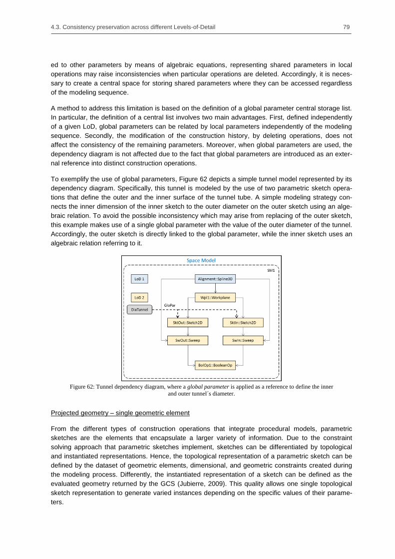
4.3. Consistency preservation across different Levels-of-Detail 79
ed to other parameters by means of algebraic equations, representing shared parameters in local
operations may raise inconsistencies when particular operations are deleted. Accordingly, it is neces-
sary to create a central space for storing shared parameters where they can be accessed regardless
of the modeling sequence.
A method to address this limitation is based on the definition of a global parameter central storage list.
In particular, the definition of a central list involves two main advantages. First, defined independently
of a given LoD, global parameters can be related by local parameters independently of the modeling
sequence. Secondly, the modification of the construction history, by deleting operations, does not
affect the consistency of the remaining parameters. Moreover, when global parameters are used, the
dependency diagram is not affected due to the fact that global parameters are introduced as an exter-
nal reference into distinct construction operations.
To exemplify the use of global parameters, Figure 62 depicts a simple tunnel model represented by its
dependency diagram. Specifically, this tunnel is modeled by the use of two parametric sketch opera-
tions that define the outer and the inner surface of the tunnel tube. A simple modeling strategy con-
nects the inner dimension of the inner sketch to the outer diameter on the outer sketch using an alge-
braic relation. To avoid the possible inconsistency which may arise from replacing of the outer sketch,
this example makes use of a single global parameter with the value of the outer diameter of the tunnel.
Accordingly, the outer sketch is directly linked to the global parameter, while the inner sketch uses an
algebraic relation referring to it.
Figure 62: Tunnel dependency diagram, where a global parameter is applied as a reference to define the inner
and outer tunnel´s diameter.
Projected geometry – single geometric element
From the different types of construction operations that integrate procedural models, parametric
sketches are the elements that encapsulate a larger variety of information. Due to the constraint
solving approach that parametric sketches implement, sketches can be differentiated by topological
and instantiated representations. Hence, the topological representation of a parametric sketch can be
defined by the dataset of geometric elements, dimensional, and geometric constraints created during
the modeling process. Differently, the instantiated representation of a sketch can be defined as the
evaluated geometry returned by the GCS (Jubierre, 2009). This quality allows one single topological
sketch representation to generate varied instances depending on the specific values of their parame-
ters.

80 Chapter 4. Consistency preservation methods for multi-scale procedural geometry representations
Consequently, parameters are able to alter the instantiated representation of a parametric sketch, but
not its topological definition. One example of this behavior can be found in the outer and inner circle
definition of a shield tunnel. Although the inner diameter of the tunnel can be defined as an offset
distance between both circles, this simple dimension does not guarantee the topological concentricity
that both circles require. Thus, when two parametric sketches must share the same topology, the
scalar information stored in global parameters is insufficient. In addition, a topological link must be
unidirectional, as this is the fundamental principle upon which the procedural models are based. In
consequence, a new topological relation is needed that enables construction operations to share
distinct topological information while keeping the dependency principle.
Although a central place to store atomic geometric elements emerges as a feasible solution, following
the methodology established for scalar values, the unidirectional requirement of topological relations
makes this approach too demanding compared with other solutions. So a novel projected geometry
dependency, similar to the standard procedural dependency, has been developed to connect pairwise
topological objects between two parametric sketches. In particular, this dependency makes singular
geometric elements of the referred sketch available to the referencing operation. Thereby, the referred
geometry becomes a constraining portion in the referenced sketch.
The same tunnel example used in the previous section can illustrate the application of the projected
geometry dependency. Using a different modeling strategy, this time the outer sketch projects its circle
onto the inner sketch operation. Then the inner sketch can use this reference as a fixed geometry to
constrain the inner circle by a concentricity geometric constraint and an offset dimension. Due to the
projected geometry dependency, if the outer sketch modifies the diameter of the tunnel, the inner
sketch will automatically update the inner geometry, maintaining the offset distance between the two
circles. Figure 63 depicts the dependency diagram for the given example.
Figure 63: Tunnel dependency diagram, where two parametric sketches are coupled by a projected geometry
dependency. In this example, the inner sketch depicts the circle element (in red) contained on the outer
sketch.
An additional key characteristic of projected dependencies is that their consistency is guaranteed
across multiple LoD. Similar to the procedural dependency behaviour, projected dependencies only
connect construction operations that are defined on the same or detailed LoD. Consequently, the
referred operation is always available in the construction history, and therefore the consistency of the
complete model is guaranteed.
4.3. Consistency preservation across different Levels-of-Detail 81
Projected geometry – complete construction operation
Combining procedural and assembly modeling strategies allows designers and engineers to perform
the multi-scale design of large infrastructure facilities in an efficient manner. As already discussed in
the previous section, the early design of coarse LoD is accomplished by means of a single procedural
model, the so-called space model (see Section 4.2.1). Later on, during the detailed design of LoD5,
the space model is extended with a hierarchy of assembly and procedural models. In particular, each
procedural model represents one physical object, while the hierarchical structure of assemblies and
sub-assemblies reproduce the semantic space structure.
This change in the modeling approach requires the automatic recognition in the space model of the
set of construction operations that generates each space object. To achieve this integration in a trans-
parent manner to the user, the semantic information contained in the product model is essential. Since
the search of the needed operations and the generation of the physical model is not a trivial task, this
methodology will be explained in detail in Section 4.3.4.
During the automatic generation of physical objects, procedural models are initialized with the space
geometry definition contained in the space model. This approach allows designers and engineers to
constrain the detailed geometry to the envelope defined by the space object. However, although this
method enables the creation of consistent procedural models, as soon as a modification on the space
model is performed, the generated physical objects will no longer be consistent. Therefore, an addi-
tional dependency is needed that preserves the consistency of two equivalent construction operations
in two different procedural models.
To achieve this requirement, the previous projected geometry dependency has been extended to
enable the projection of one construction operation within a referencing model. In particular, this
projection is differentiated depending on which type of construction operation is applied:
In the case of parametric sketches, only their instantiated representation is projected. As the
geometry in the referencing model is locked in front of manual modifications, the parameters
and constraints defined into the referenced sketch do not need to be transferred.
In the case of creation or sketch-based operations including parameters, these are projected
as fixed values. Where parameters define an algebraic equation, their value is evaluated be-
fore the projection.
To illustrate the use of complete projected geometry dependencies, Figure 64 depicts an example of a
tunnel concrete floor. First, the geometry defining the space object is defined in the space model by
four construction operations distributed across three LoD. Later, a second procedural model is gener-
ated representing the physical element. In this second model, contained in an assembly structure, four
dependencies establish a relation with their original definition in the space model. Finally, the designer
can carry on with the detailing process, while the complete projected geometry dependencies preserve
the consistency of the model in the case of modifications regarding the space or the alignment defini-
tion.

82 Chapter 4. Consistency preservation methods for multi-scale procedural geometry representations
Figure 64: Example of a tunnel concrete floor represented (left) in the space model as a space object and
(right) as a physical entity in an assembly structure. The four initial construction operations of the physical
model are projected from their definition of the space model.
4.3.4. Automatic generation of physical objects out of space objects
In the previous section has been shown how projected dependencies guarantee the consistency
between construction operations defined in the space model and the generated physical object mod-
els. The generation of such physical models out of spaces is not a trivial problem. The main challenge
in the generation process resides on the identification of construction operations that fully define a
space object.
To solve this technological problem a novel algorithm has been developed to extract the required
information from the space model and to automatically generate the physical part model. The pro-
posed algorithm makes use of the available semantic information contained on the product model to
find out the construction operation related to a particular space definition. Once this construction
operation is known, the rest of the required operations can be extracted by recursively searching on
the parent relations in the dependency diagram. Finally, the placement of physical parts is achieved by
the generation in each physical part of a local coordinate system that is later matched with the origin of
the assembly.
The developed algorithm comprises four steps:
Step 1 – Identification of the construction operation that is associated with a specific space.
This construction operation, named as the conclude operation, is the only element that relates
the semantic and geometry models. On the simple example depicted on Figure 64 the con-
clude operation is the sweep operation, which is related to the semantic space object concrete
floor.
Step 2 – Starting from the conclude operation, a recursive search on the parent dependencies
results in a thorough identification of the complete set of construction operations that generate
the space geometry.
Step 3 – Generation of a new procedural model for each physical object contained in a space
definition. The construction history of these procedural models is initialized with a copy of the
extracted operations and connected to the space model by means of projected dependencies.

4.4. Consistency preservation across different submodels 83
Step 4 – Integration of the generated models into an assembly structure. This step constrains
the global coordinate system on the physical procedural models with the one on the assembly
structure.
4.4. Consistency preservation across different submodels
4.4.1. Overview
A widespread methodology employed on the design of large infrastructure facilities is to divide the
entire project into several sections or parts. Based on diverse criteria such as budget disposal or
geographical distribution, this subdivision enables an optimized use of the available resources. Thus,
by dividing the project into several sections, the design process can be performed in parallel, reducing
development times, and maximizing the allocation of resources (Dori 2016).
The geometric subdivision of the infrastructure model into several sections does not have a single
solution. A straightforward strategy is the generation of independent geometric models, one for each
section. Done in this way, engineers and designers can independently work on different model files,
achieving the desired optimization of resources. However, the main drawback of this approach is the
lack of consistency among the different models. One example can be found in the common size of the
cross-section in a shield tunnel. Every time an engineer updates the diameter of the tunnel, he must
be aware that the same change must be also implemented in the other model files in order to avoid
inconsistencies on the project. In conclusion, the strategy of subdividing the geometry into several
model files requires external management to avoid inconsistencies. A process that is time-consuming
and error-prone.
To solve this technological problem, this thesis proposes the subdivision of the infrastructure model
into several sections as part of the same procedural model. In particular, the proposed approach
creates clusters of construction operations that do not interact with other clusters. Consequently,
infrastructure sections can be modified independently, while the complete project is contained in the
same model file. To preserve the consistency of the model, novel dependencies must be defined
among equivalent procedural operations contained in distinct clusters. This section describes the
consistency requirements of infrastructure clustering and proposes a novel approach to achieve con-
sistency between consecutive infrastructure sections.
4.4.2. Including the concept of submodels in procedural models
The alignment is the main feature employed to completely describe large infrastructure facilities. In
combination with a single cross-section, a section of the alignment curve can represent a complete
area of the infrastructure facility. In addition, these sections are frequently subdivided into smaller
parts to optimize the resources invested in the design process. Since the reasoning applied by de-
signers and engineers to decide the length of such parts is usually more related to the specific needs
of the project than to geometric requirements, henceforth in this thesis, a subdivision based on the
horizontal description of the alignment will be used. In particular, the alignment curve will be subdivid-
ed in a way that emulates the amount and length of the elements contained in its horizontal descrip-
tion.
Once the alignment is subdivided, engineers apply equivalent construction operations to each section.
Although the outcome geometry on each section is different, they are topologically identical, i.e. the
geometry is generated by the same collection of construction operations, sweeping a different path

84 Chapter 4. Consistency preservation methods for multi-scale procedural geometry representations
curve. Moreover, construction operations, regardless of their location on the construction history, do
not establish dependencies with their equivalent modeled subdivisions, enabling their clustering and
local modification. Thereby, each of these modelled subdivisions are referred to as submodels, and
formally defined as clusters of construction operations that fully define one section of an infrastructure
facility.
This modeling approach, based on the subdivision of an infrastructure section into several submodels,
does not influence the consistency preservation methodology applied across different LoD. However,
having several topological equivalent submodels creates the potential risk of inconsistencies across
different submodel definitions. As an example, Figure 65 depicts one simple tunnel model represented
up to its LoD4, and divided into three submodels. In the given example, if the diameter of the initial
cross-section is altered, the same modification must be performed on the other two submodels, or the
model will become inconsistent.
Therefore, in the scope of this thesis, cross-submodel consistency is defined as the capability of a
procedural model to modify a single submodel, while keeping the consistency between its topological
equivalent submodels.
Figure 65: A tunnel infrastructure model divided into three submodels. In addition to the consistency re-
quirements of multi-scale models, the submodel approach introduces a new source of inconsistency that has
to be addressed.
Although cross-LoD consistency methods are also used to guarantee the continuity and consistency of
the complete model, the design based on submodels requires a novel type of dependencies that allow
geometric elements to adapt themselves to the changing boundary conditions. One example of this
requirement can be found in the design of the track-bed. Although global parameters and projected
geometry methods emerge as the optimal solution to guarantee the stepwise continuity between the
different submodels, these methods can only handle exact copies of the geometry, and are therefore
unable to adapt the projected cross-section to the changing value of the super-elevation. In short, new
dependencies are needed that project in a flexible way, not only the geometry, but also parameters
and constraints, creating flexible objects that can adapt themselves to the specific requirements of
varying boundary conditions.

4.4. Consistency preservation across different submodels 85
4.4.3. Cross-submodel consistency methods
In this section two main limitations of the infrastructure modeling based on submodels are addressed.
First, the required consistency between equivalent sketches placed in different submodels is ad-
dressed by the definition of master-copy dependencies that relate the copied sketches with a single
master sketch. Secondly, the limitation of placing geometry along several submodels is addressed by
the use of dynamic dependencies, which in turn minimizes the depending submodels.
Master-copy sketch dependency
Different sections of roads, bridges and tunnels are frequently defined by equivalent cross-sections
that only vary in some of their basic dimensions. However, isolated by definition, submodels cannot
define procedural dependencies to other parametric sketches outside their cluster. Consequently, this
isolation of parametric sketches becomes de facto the main source of geometric inconsistencies when
modeling with submodels.
To close this technological gap, a dependency type based on a master-copy pattern has been devel-
oped. In particular, this dependency type defines a single master sketch that defines the geometry,
constraints and parameters of the primary cross-section. The copy sketches replicate this information
assigning differing values to the parameters as required. Specifically, the parameters of the copied
sketches are either overridden with new values or defined through an arithmetic expression that links a
local margin parameter with the corresponding parameter on the master-sketch. In consequence, copy
sketches provide a topological identical but morphological deviating version of the master sketch.
Figure 66: A master-sketch (in dashed red color) and its three copied sketches (in continuous blue color) de-
fine the railway clearance gauge. The copied parameters are related to the master-sketch except the one which
defines the slope of the super-elevation stripe that is overridden.
Applications of the master-copy dependency can be found in a wide number of engineering problems.
A first example that overrides one of the parameters defined in the master sketch can be found in the
clearance gauge. Thus, the master sketch defines a rotation angle that is initialized with a fixed value
associated to the super-elevation of the track. Although the copy sketches are replicated from the
master, the angle parameter will be accordingly overridden in relation with the speed and the curvature

86 Chapter 4. Consistency preservation methods for multi-scale procedural geometry representations
radius at every placement position. A second example is the storing of the annular gap grout deviation
on shield tunnels (Thewes and Budach 2009, Hegemann et al, 2014) Although this constructive devia-
tion is frequently stored and classified as semantic information, the tolerance parameter introduced on
the copy sketches can be used to additionally register this information in a geometrical representation
manner.
Figure 67: Dependency diagram of a tunnel model designed using three submodels. To guarantee the con-
sistency among the parametric sketches a master-copy dependency has been introduced, where the sketch in
the submodel SM1 is considered the master.
Adding master-copy dependencies in the procedural model do not alter the given dependency system.
Specifically, master-copy dependencies establish direct relations between the master sketch and each
of the copy sketches. However, these dependencies are managed externally to the parametric CAD
system and therefore do not invalidate the submodel approach. Figure 67 depicts the dependency
diagram of a tunnel model that employs master-copy dependencies to guarantee the cross-submodel
consistency. The presented tunnel model is divided into three submodels from which the first defines
the master sketch and the last two the copy sketches.
Dynamic dependency
During the design of large infrastructure facilities stationing points are frequently used to place auxilia-
ry elements such as road signs, traffic lights, and ventilation booster-fans. Measured along the align-
ment, stationing points give engineers and designers the flexibility to locate elements independently of
their geographic coordinates. However, a local modification on the alignment affects all the auxiliary
elements placed downstream.
To illustrate this problem, Figure 68 represents the alignment of an infrastructure facility with one
object placed on a given stationing point. The modeling strategy described in this thesis would divide
the alignment into three submodels and place the object along the second spline by means of one
positioning parameter. Defined as the local distance between the starting and object stationing points,
if a shortening modification on the first spline is performed, the value of the positioning parameter
could be greater than the length of the spline and then the object cannot be longer placed. The
straightforward solution to this problem is to integrate all the splines in order that the positioning pa-
rameter would be always able to place the desired object. However, this solution creates procedural
dependencies among the construction operations, invalidating the submodel approach.

4.4. Consistency preservation across different submodels 87
Figure 68: Placement of one auxiliary element based on its stationing.
To enable the unambiguous placement of auxiliary elements at the time that preserves the submodel
approach, this thesis presents a novel dynamic dependency that establishes a single dependency
relation among a set of feasible construction operations. In particular, the dynamic dependency stores
in a sorted table the set of construction operations and the range of values for which they are effective.
Consequently, after the modification of one of these construction operations, the table is updated and
if necessary the procedural dependency accordingly reassigned.
Both properties of dynamic dependencies have been introduced into dependency diagrams. First, all
dependencies between feasible construction operations are represented in the diagram. Secondly,
only the established dependency is described as Active. To exemplify the use of dynamic dependen-
cies Figure 69 depicts one simple tunnel model split into two submodels. Additionally, the exit to a
rescue shaft, modelled as a third submodel, is dynamically attached to the alignment of the tunnel.
Subsequently, both feasible dependencies are represented by a dashed line and only the one which is
related is marked as active.
Figure 69: Dependency diagram of a tunnel model and a rescue shaft. The placement of the rescue shaft is
based on a stationing point and attached to the alignment splines by means of a dynamic dependency.
4.4.4. Automatic coupling of submodels and non-linear models
The main characteristic that defines large infrastructure facilities is its alignment. Roads, bridges and
tunnels define complete sections of the infrastructure facility built upon its alignment and a single
cross-section. From its linear behavior such modelled sections received the name of linear models. In
opposition, there is a second type of infrastructure buildings that does not follow this linear pattern.
Rescue shafts, tunnel cross passages, and bridge piles are examples of infrastructure elements that
are attached to linear-models on a given stationing point. Therefore, and due to their loose coupling to
the alignment, such infrastructure elements are denoted as non-linear models.

88 Chapter 4. Consistency preservation methods for multi-scale procedural geometry representations
Parametric non-linear models have the advantage that they can be designed independently as a
separate procedural model and stored as a template in a domain-specific library. Later on, if properly
defined, non-linear models automatically adapt themselves to fulfill the given boundary conditions.
Furthermore, non-linear models can be treated as additional submodels of the procedural model,
which can be replaced and moved freely along the alignment by means of dynamic dependencies.
One example of a non-linear model is shown in Figure 70 where a rescue shaft is attached to a tunnel
model. In particular, the tunnel axis and tunnel hollow surface are used as boundary conditions by the
rescue shaft and a collection of design parameters – such as the depth of the shaft or the length of the
corridor area – determine the final shape from a large range of possible scenarios.
Figure 70: Rescue shaft (non-linear model) attached to a tunnel model (linear model).
Automatic coupling algorithm for non-linear models
The coupling of non-linear models with procedural models implies overcoming two main limitations,
namely, the renaming of the construction operations and the definition of new procedural dependen-
cies. First, procedural models cannot contain two construction operations defined with the same name,
which is of particular relevance if the same template model is introduced several times. If that case
occurs, the dependency diagram will become inconsistent and the procedural model can no longer be
resolved. Therefore, every time a non-linear model is introduced in a procedural model a renaming
procedure must be executed. Secondly, during the design of non-linear models, construction opera-
tions are introduced in the procedural description that simulates the boundary conditions of the receiv-
ing linear model. Those additional construction operations do not need to be transferred as the linear
model contains their equivalent. As consequence, some of the dependencies of the non-linear model
must be reassigned with the construction operations defining the boundary conditions of the linear
model.
From the second limitation arise the challenge of recognizing the construction operations that act as
boundary condition. To confront this limitation an attribute has been added to the definition of every
construction operation that determines the role of the operation in the non-linear model. This attribute
must be defined as one of the three following options:
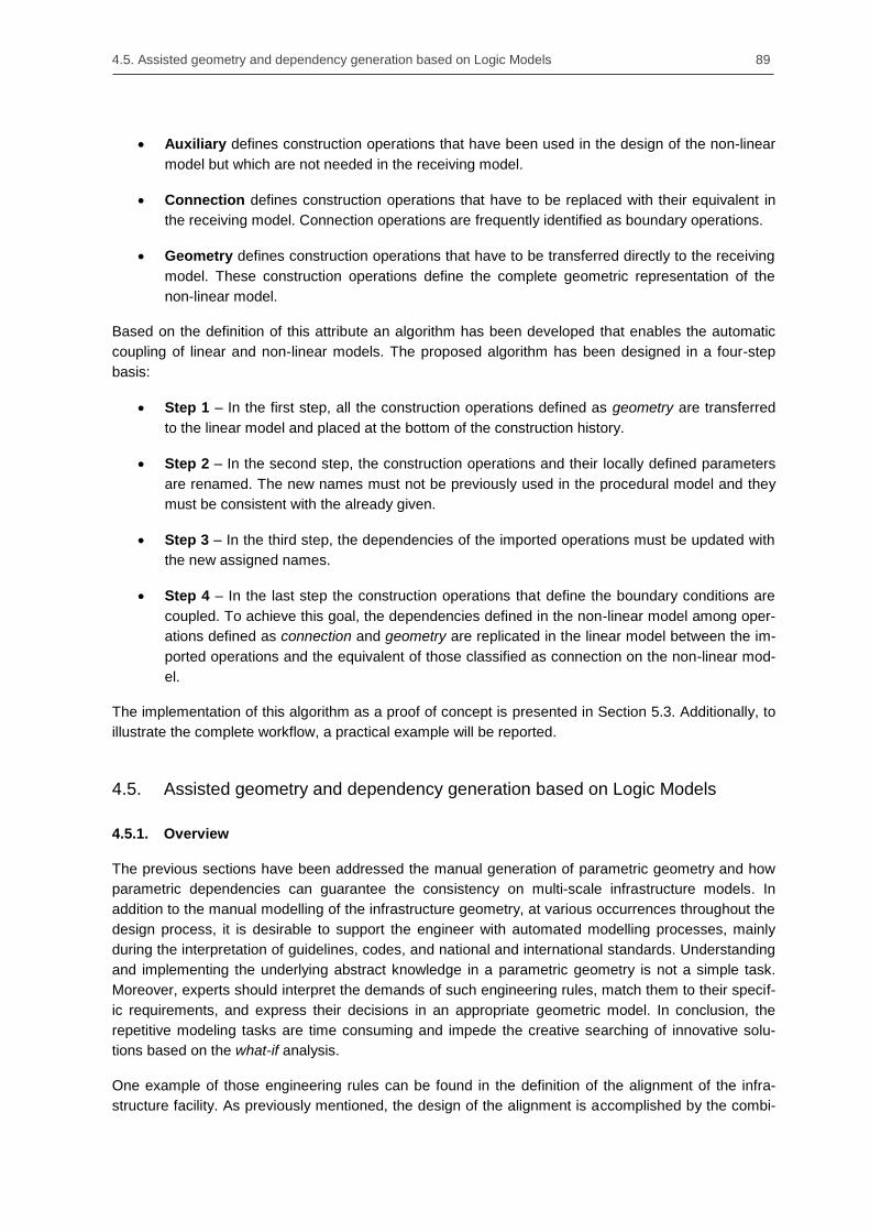
4.5. Assisted geometry and dependency generation based on Logic Models 89
Auxiliary defines construction operations that have been used in the design of the non-linear
model but which are not needed in the receiving model.
Connection defines construction operations that have to be replaced with their equivalent in
the receiving model. Connection operations are frequently identified as boundary operations.
Geometry defines construction operations that have to be transferred directly to the receiving
model. These construction operations define the complete geometric representation of the
non-linear model.
Based on the definition of this attribute an algorithm has been developed that enables the automatic
coupling of linear and non-linear models. The proposed algorithm has been designed in a four-step
basis:
Step 1 – In the first step, all the construction operations defined as geometry are transferred
to the linear model and placed at the bottom of the construction history.
Step 2 – In the second step, the construction operations and their locally defined parameters
are renamed. The new names must not be previously used in the procedural model and they
must be consistent with the already given.
Step 3 – In the third step, the dependencies of the imported operations must be updated with
the new assigned names.
Step 4 – In the last step the construction operations that define the boundary conditions are
coupled. To achieve this goal, the dependencies defined in the non-linear model among oper-
ations defined as connection and geometry are replicated in the linear model between the im-
ported operations and the equivalent of those classified as connection on the non-linear mod-
el.
The implementation of this algorithm as a proof of concept is presented in Section 5.3. Additionally, to
illustrate the complete workflow, a practical example will be reported.
4.5. Assisted geometry and dependency generation based on Logic Models
4.5.1. Overview
The previous sections have been addressed the manual generation of parametric geometry and how
parametric dependencies can guarantee the consistency on multi-scale infrastructure models. In
addition to the manual modelling of the infrastructure geometry, at various occurrences throughout the
design process, it is desirable to support the engineer with automated modelling processes, mainly
during the interpretation of guidelines, codes, and national and international standards. Understanding
and implementing the underlying abstract knowledge in a parametric geometry is not a simple task.
Moreover, experts should interpret the demands of such engineering rules, match them to their specif-
ic requirements, and express their decisions in an appropriate geometric model. In conclusion, the
repetitive modeling tasks are time consuming and impede the creative searching of innovative solu-
tions based on the what-if analysis.
One example of those engineering rules can be found in the definition of the alignment of the infra-
structure facility. As previously mentioned, the design of the alignment is accomplished by the combi-

90 Chapter 4. Consistency preservation methods for multi-scale procedural geometry representations
nation of two plane curves. For the horizontal alignment, which describes the curvature related to the
XY-plane, engineers have to define parameters such as the minimal radius of curvature or the clothoid
constant for the connection curves, which later influence the cant and the ―smoothness‖ of the driving
in a track. Similarly, for the vertical alignment, engineers must decide the values of the parameters that
rule the length of crest and sag curves or the slope between two kilometric points. Finally, the infor-
mation of both curves must be combined in order to generate one or more 3D spatial curves.
Figure 71: Alignment of an infrastructure as a combination of its horizontal and vertical alignment curves
One essential benefit of modeling these engineering rules in a parametric CAD system is that the
outcome geometry produced after applying the rule is enclosed in a few construction operations that
can be easily recognized and isolated in the construction history. Further, the interpretation of such
engineering rules can be easily encapsulated in a way that the user only needs to provide the input
information, e.g. the horizontal and vertical alignments, and leave the system return a new or updated
procedural geometry.
Consequently, this section introduces the novel concept of logic models as an assisted generative
methodology integrated in the modeling process with parametric CAD systems. In particular, each
logic model encapsulates a well-defined engineering rule and is able to interpret the input parameters
and to generate a corresponding set of procedural operations. This approach also allows engineers
and experts to modify complete sections of an infrastructure facility by the simple modification of a
parameter, and to visualize the resulting geometry almost instantaneously.
Figure 72: Rescue shaft attached to a subway tunnel in two different locations. The generation and modifica-
tion of such geometries can easily be managed using logic models.
4.5.2. Logic Model definition
As discussed previously, there are two methods that can capture the intention engineers apply on the
design of large infrastructure facilities, i.e., the semantic information and the design intent. On the one
hand, semantic models are mainly library structures that store attributes of specific building elements.
Some of those attributes can also be defined as parameters and used to modify existing geometry in
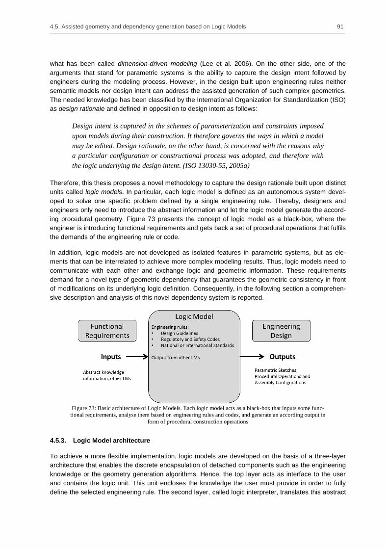
4.5. Assisted geometry and dependency generation based on Logic Models 91
what has been called dimension-driven modeling (Lee et al. 2006). On the other side, one of the
arguments that stand for parametric systems is the ability to capture the design intent followed by
engineers during the modeling process. However, in the design built upon engineering rules neither
semantic models nor design intent can address the assisted generation of such complex geometries.
The needed knowledge has been classified by the International Organization for Standardization (ISO)
as design rationale and defined in opposition to design intent as follows:
Design intent is captured in the schemes of parameterization and constraints imposed
upon models during their construction. It therefore governs the ways in which a model
may be edited. Design rationale, on the other hand, is concerned with the reasons why
a particular configuration or constructional process was adopted, and therefore with
the logic underlying the design intent. (ISO 13030-55, 2005a)
Therefore, this thesis proposes a novel methodology to capture the design rationale built upon distinct
units called logic models. In particular, each logic model is defined as an autonomous system devel-
oped to solve one specific problem defined by a single engineering rule. Thereby, designers and
engineers only need to introduce the abstract information and let the logic model generate the accord-
ing procedural geometry. Figure 73 presents the concept of logic model as a black-box, where the
engineer is introducing functional requirements and gets back a set of procedural operations that fulfils
the demands of the engineering rule or code.
In addition, logic models are not developed as isolated features in parametric systems, but as ele-
ments that can be interrelated to achieve more complex modeling results. Thus, logic models need to
communicate with each other and exchange logic and geometric information. These requirements
demand for a novel type of geometric dependency that guarantees the geometric consistency in front
of modifications on its underlying logic definition. Consequently, in the following section a comprehen-
sive description and analysis of this novel dependency system is reported.
Figure 73: Basic architecture of Logic Models. Each logic model acts as a black-box that inputs some func-
tional requirements, analyse them based on engineering rules and codes, and generate an according output in
form of procedural construction operations
4.5.3. Logic Model architecture
To achieve a more flexible implementation, logic models are developed on the basis of a three-layer
architecture that enables the discrete encapsulation of detached components such as the engineering
knowledge or the geometry generation algorithms. Hence, the top layer acts as interface to the user
and contains the logic unit. This unit encloses the knowledge the user must provide in order to fully
define the selected engineering rule. The second layer, called logic interpreter, translates this abstract

92 Chapter 4. Consistency preservation methods for multi-scale procedural geometry representations
knowledge into a set of neutral – CAD system independent – procedural operations that parametric
systems cannot directly employ. Finally, the geometry layer receives the neutral information from the
logic interpreter and converts it into a set of proprietary procedural operations specifically for one
parametric system. In the following a formal description of every layer is provided.
Figure 74: Logic model three-layer architecture.
Logic Unit (LU)
The logic unit embodies the abstract knowledge the engineer must provide to fulfil the requirements of
the engineering rule. This unit remains independent of the CAD system and its information can be
captured by a graphical user interface or defined by an external tool. Thus, the information can be
submitted in two ways: (1) based on the knowledge contained in a built model or (2) by the direct
application of a neutral data format.
When the logic unit is described by a built model, its definition is close to the formal model described in
the MOKA approach, which is usually modelled using the MOKA Modeling Language (MML) (Stokes
2001). Although MML was originally derived from the UML modeling language, during the research
stage undergone for this thesis it was decided not to use MOKA and to stick with the UML language.
This decision was taken to reduce the amount of specific requirements needed to test the possibilities
logic units can offer to anyone without previous experience on system engineering process. On the
other hand, the literature describes other modeling languages – e.g. Alloy or SysML – that can be
used instead (Bailey et al. 2004, He 2006).
Although the majority of neutral data formats were not originally developed to exchange engineering
rules, their content can be used as structure to capture and initialize the information of the logic model.
One example of this novel usage of neutral data formats can be found in the alignment‘s definition.
Based on a similar principle of horizontal and vertical separation of the alignment, several data formats
became a standard among planning offices, e.g. LandXML developed by Autodesk, and OKSTRA
developed by BASt (Rebolj et al. 2008, Schultze and Buhmann 2008).
Logic Interpreter (LI)
The main task of the logic interpreter is to translate the abstract knowledge represented by the logic
unit into a set of neutral procedural operations. In the scope of this thesis a neutral data model was
developed that supports the exchange of procedural geometries among parametric CAD systems and
which was successfully validated by enabling the exchange between the two parametric systems,
Autodesk Inventor and Siemens NX (see Section 5.3., Borrmann et al., 2014).

4.5. Assisted geometry and dependency generation based on Logic Models 93
Although the standard input information for the interpreter is obtained from its logical unit, interpreters
can also handle neutral procedural operations produced by other interpreters. This property enables
the linking of several logic models and together with its dependency system will be explained in the
next section.
Similar to the definition of the logic unit, logic interpreters are defined independent of the selected
parametric system and therefore executed externally. Consequently, the development of a logic inter-
preter can be realized by software engineers in any available programing language.
Geometry Layer (GL)
Differently to the previously described layers, the geometry layer is embedded in the parametric sys-
tem. Implementing this layer as a CAD module enables the geometry layer to accomplish two main
tasks: first, to convert the neutral procedural operations into a set of proprietary construction opera-
tions that a specific CAD system can handle, and secondly, to lock the generated operations with
respect to manual modification of the user and thereby to avoid inconsistencies on the model.
The proprietary characteristics of construction operations force geometric layers to be implemented
accordingly for the parametric system selected. However, this need does not mean that a geometry
layer must embed so many different implementations as possible parametric CAD systems working on
the same project. Usually engineers complete their design in a single parametric system and therefore
only one implementation is needed. At the time to exchange the model, if a modification is required,
the receiving CAD system will require a suitable geometry layer.
Figure 75: Integration of a Logic Model with two different CAD systems. The Logic Unit and the Logic In-
terpreter are independent of the CAD system selected while the Geometry Layer must be specifically defined
for each system. Arrows shows the information exchange fluxes between layers. This figure does not imply
the parallel or simultaneous use on two CAD systems.
Due to fact that several logic models working on the same parametric system may require to convert
the same type of neutral construction operations, e.g. parametric sketches, swept volumes, and Bool-
ean operations, the strategy of using a common geometry layer can reduce the implementation effort.
Doing so, the common geometry layer acts as an interface between the different logic models and the
parametric system. Additionally, having several geometry layers concentrated in a common geometry
layer allows developers to enhance and update operation converters in a faster and consistent way.

94 Chapter 4. Consistency preservation methods for multi-scale procedural geometry representations
4.5.4. Consistency methods across different levels-of-detail
As the design of an infrastructure facility evolves, the knowledge needed to model it becomes also
more complex. To avoid repetition in the knowledge‘s definition and the need of developing logic
models that describes all possible scenarios, several logic models can be horizontally connected to
create a compound modeling.
Figure 76: Tunnel model designed upon the alignment and tunnel axis curves.
A simple example of two logic models that can be linked to provide a more complex modeling can be
found in the alignment and axis curves of a ring tunnel, placed respectively on LoD1 and LoD2. On the
one hand, the logic model of the alignment contains the needed information to create a spatial-curve –
described by the mid curve between the two rails – based on the horizontal and vertical alignments.
On the other hand, the logic model responsible for the tunnel axis – used to guide the Tunnel Boring
Machine (TBM) – creates a second spatial-curve that is shifted from the alignment curve by vertical
and horizontal parameters. As the tunnel axis is based on the curve described by the alignment, both
models can be linked to avoid redundancy and logic‘s complexity. Hence, a modification in the align-
ment model will update the geometry of the alignment and the axis curve – even when the tunnel axis
model remains unchanged.
Figure 77: Integration of two Logic Models within one CAD system. The two logic models are linked
through the logic interface layer to generate a more complex knowledge.
This behavior is achieved by horizontal connectors, which allow logic models to communicate among
each other. Horizontal connectors implement a one-to-many communication that propagates the
changes and the logic content from the related model to the linked models.

4.5. Assisted geometry and dependency generation based on Logic Models 95
Horizontal connectors
Although the workflow in the logic model is mainly top-down, from the logic unit to the geometry layer,
several logic models can be horizontally connected to create a more complex modeling. Horizontal
connections are defined as a one-to-many relationship and their communication are only granted
between connectors of the same type. In addition, horizontal connections provide two different types
of communication between logic models, i.e. the active and the passive connection.
The active connection enables all linked models to get informed when an update arises in the related
logic model. To implement this communication strategy the widely known observer-pattern has been
used (Gamma et al., 1995). This pattern defines two main elements, known as subject and observer
objects. The subject object sends out update notifications without knowing who are getting them, while
the observer object is subscribing the notifications broadcasted by a subject object. Thus, after getting
a notification, the linked model can start an update process to collect the changes.
To represent the relations among several models a novel Logic Model Diagram (LMD) is employed,
where the nodes are the logic models and the edges the horizontal connections between models. To
differentiate the horizontal connections, two connectors were placed at the extremes of the edges that
are colored differently whether they are source- or sink-connectors. This nomenclature follows the
concepts of subject and observer objects. Finally, every connector is represented by one letter that
identifies its exchanged information. One example of a LMD is shown in Figure 78.
Figure 78: Example of a simple logic model diagram (LMD). The source-connector (black) of the alignment
model is communicating its changes with the sink-connector (grey) placed in the tunnel axis model. ‘T’ is the
connectors’ name that identifies them in front other connector types.
The passive connection enables linked logic models to access anytime the information contained in
the related logic model. This communication is mainly taking place during the model‘s initialization
process when the logic interpreter is firstly executed and the neutral geometry created.
Due to the fact that each logic model pre-defines its own connections, as soon as a new logic model is
instantiated in the modeling process the system will grant its communication. In case the expected
related model does not exist, the system will not allow the logic model to be initialized and an error will
be generated.
Parametric consistency preservation built upon horizontal connectors
During the design process, each time a logic model is applied a new set of procedural operations are
added at the end of the construction history. This behavior, together with the fact that logic models
input can only be defined by abstract information or by other logic models output, results in the fact
that the dependency diagram of the existing model is not altered and its global consistency is guaran-
teed. In addition, as the construction operations generated by the logic model are native operations of
the parametric system, every further modeling based on those operations will be consistently updated
by the dependencies of the parametric CAD system.
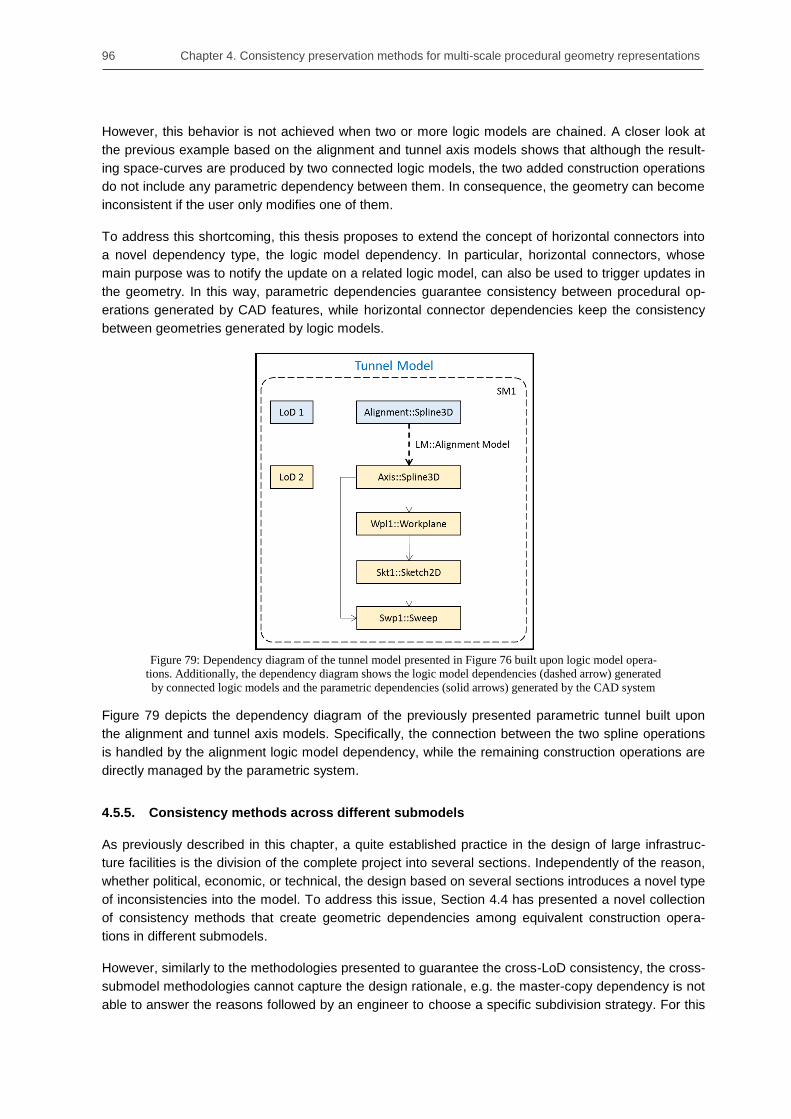
96 Chapter 4. Consistency preservation methods for multi-scale procedural geometry representations
However, this behavior is not achieved when two or more logic models are chained. A closer look at
the previous example based on the alignment and tunnel axis models shows that although the result-
ing space-curves are produced by two connected logic models, the two added construction operations
do not include any parametric dependency between them. In consequence, the geometry can become
inconsistent if the user only modifies one of them.
To address this shortcoming, this thesis proposes to extend the concept of horizontal connectors into
a novel dependency type, the logic model dependency. In particular, horizontal connectors, whose
main purpose was to notify the update on a related logic model, can also be used to trigger updates in
the geometry. In this way, parametric dependencies guarantee consistency between procedural op-
erations generated by CAD features, while horizontal connector dependencies keep the consistency
between geometries generated by logic models.
Figure 79: Dependency diagram of the tunnel model presented in Figure 76 built upon logic model opera-
tions. Additionally, the dependency diagram shows the logic model dependencies (dashed arrow) generated
by connected logic models and the parametric dependencies (solid arrows) generated by the CAD system
Figure 79 depicts the dependency diagram of the previously presented parametric tunnel built upon
the alignment and tunnel axis models. Specifically, the connection between the two spline operations
is handled by the alignment logic model dependency, while the remaining construction operations are
directly managed by the parametric system.
4.5.5. Consistency methods across different submodels
As previously described in this chapter, a quite established practice in the design of large infrastruc-
ture facilities is the division of the complete project into several sections. Independently of the reason,
whether political, economic, or technical, the design based on several sections introduces a novel type
of inconsistencies into the model. To address this issue, Section 4.4 has presented a novel collection
of consistency methods that create geometric dependencies among equivalent construction opera-
tions in different submodels.
However, similarly to the methodologies presented to guarantee the cross-LoD consistency, the cross-
submodel methodologies cannot capture the design rationale, e.g. the master-copy dependency is not
able to answer the reasons followed by an engineer to choose a specific subdivision strategy. For this
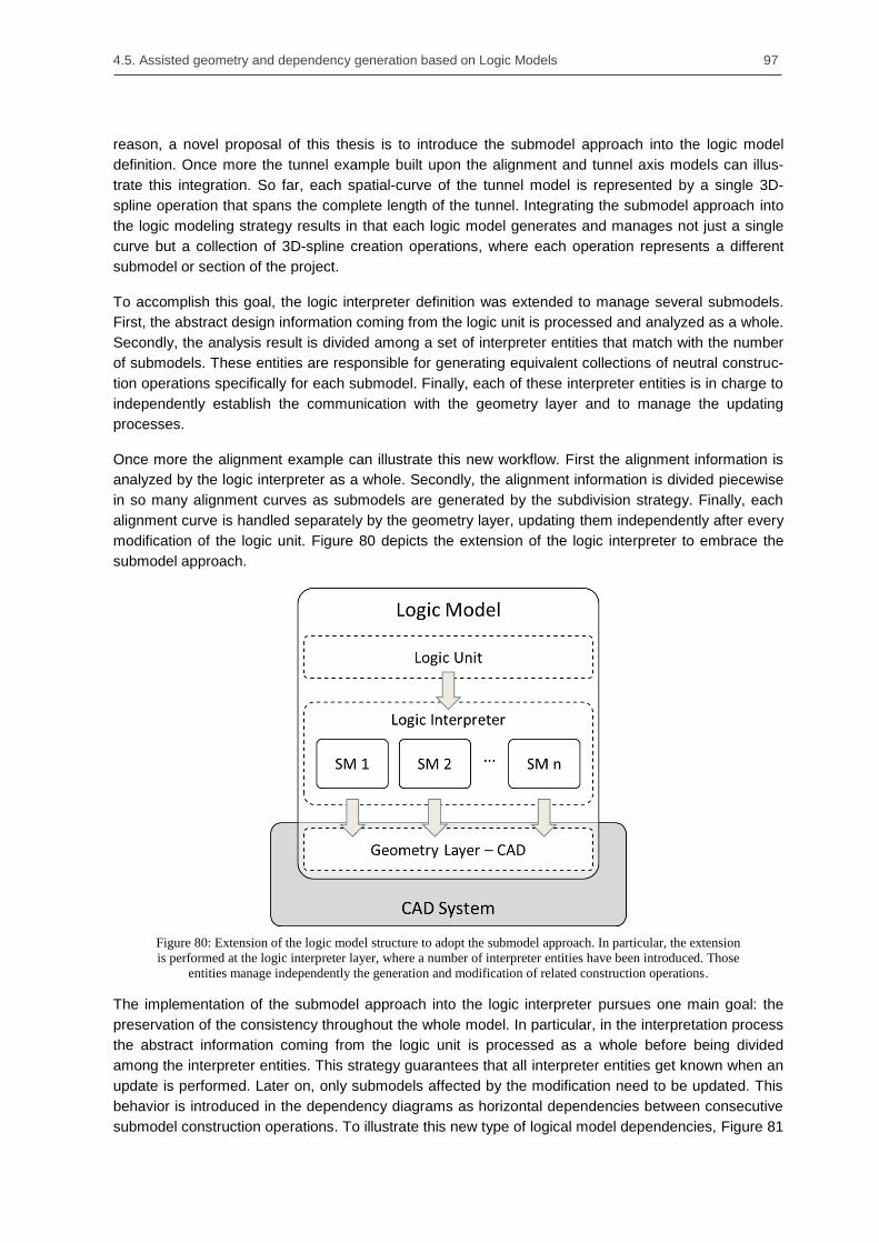
4.5. Assisted geometry and dependency generation based on Logic Models 97
reason, a novel proposal of this thesis is to introduce the submodel approach into the logic model
definition. Once more the tunnel example built upon the alignment and tunnel axis models can illus-
trate this integration. So far, each spatial-curve of the tunnel model is represented by a single 3D-
spline operation that spans the complete length of the tunnel. Integrating the submodel approach into
the logic modeling strategy results in that each logic model generates and manages not just a single
curve but a collection of 3D-spline creation operations, where each operation represents a different
submodel or section of the project.
To accomplish this goal, the logic interpreter definition was extended to manage several submodels.
First, the abstract design information coming from the logic unit is processed and analyzed as a whole.
Secondly, the analysis result is divided among a set of interpreter entities that match with the number
of submodels. These entities are responsible for generating equivalent collections of neutral construc-
tion operations specifically for each submodel. Finally, each of these interpreter entities is in charge to
independently establish the communication with the geometry layer and to manage the updating
processes.
Once more the alignment example can illustrate this new workflow. First the alignment information is
analyzed by the logic interpreter as a whole. Secondly, the alignment information is divided piecewise
in so many alignment curves as submodels are generated by the subdivision strategy. Finally, each
alignment curve is handled separately by the geometry layer, updating them independently after every
modification of the logic unit. Figure 80 depicts the extension of the logic interpreter to embrace the
submodel approach.
Figure 80: Extension of the logic model structure to adopt the submodel approach. In particular, the extension
is performed at the logic interpreter layer, where a number of interpreter entities have been introduced. Those
entities manage independently the generation and modification of related construction operations.
The implementation of the submodel approach into the logic interpreter pursues one main goal: the
preservation of the consistency throughout the whole model. In particular, in the interpretation process
the abstract information coming from the logic unit is processed as a whole before being divided
among the interpreter entities. This strategy guarantees that all interpreter entities get known when an
update is performed. Later on, only submodels affected by the modification need to be updated. This
behavior is introduced in the dependency diagrams as horizontal dependencies between consecutive
submodel construction operations. To illustrate this new type of logical model dependencies, Figure 81

98 Chapter 4. Consistency preservation methods for multi-scale procedural geometry representations
depicts the dependency diagram of the previous tunnel model built upon two submodels. The depend-
ency diagram shows how novel logic model dependencies have been added between equivalent
construction operations.
Figure 81: Dependency diagram of the tunnel model presented in Figure 76 built upon two submodels and
two logic models. To guarantee the consistency among submodels logic models introduce a novel type of hor-
izontal dependency between equivalent construction operations.
4.6. Summary
This chapter explains a novel modeling strategy that has been developed based on the integration of
parametric geometries into conventional product models. Hence, the design of the coarser LoDs (up to
LoD4) is performed in a single procedural geometric model called space model. This model encapsu-
lates the complete space structure and all the submodels in which the infrastructure is subdivided,
guaranteeing its complete consistency. Differently, for the detailed LoD5, a dual-design approach has
been followed that combines the use of assembly and procedural geometries.
However, the combined use of assembly and procedural geometries as a novel multi-scale geometric
representation is likely to suffer from inconsistencies that parametric systems are not able to address.
Therefore, this chapter presents four new dependency methods that extend the basic capabilities of
the procedural dependency system. Three of these dependency methods focus on requirements of
the space model in coarser LoD, while the last method centers on the dependency system needed
during the detailing in LoD5.
Moreover, the subdivision of the geometric model into smaller parts or submodels is a reasonably
established practice applied during the infrastructure design. This practice requires additional depend-
encies in order to keep the step-wise consistency throughout the model. Thus, this chapter introduces
two new dependency types that guarantee the consistency between submodels, and enable the
dynamic placement of non-linear submodels along the infrastructure alignment.
An additional difficulty during the infrastructure design is the interpretation of engineering rules. Hence,
this chapter presents a novel methodology that assists designers and engineers in the generation of
geometry and required dependencies at the time of implementing complex engineering rules. This
methodology encapsulates the underlying generation knowledge in discrete units named logic models

4.6. Summary 99
that convert the abstract information into a corresponding parametric geometry model. Furthermore,
logic models include two main features, namely, (1) the capability of handling several submodels at a
time and (2) the possibility of connecting two or more logic models horizontally to create a more com-
plex modeling. In addition, these two features of logic models were introduced as novel dependencies
into the procedural dependency system.
Table 1 summarizes the different dependencies presented in this chapter, where each dependency is
represented by its name, type of dependency, and section where it is fully described.
Table 1: Summary of the different procedural dependencies developed on this chapter.
Dependency name Dependency type Section
Construction history Cross-LoD 4.3.3
Global parameter Cross-LoD 4.3.3
Projected geometry – Single geometric element Cross-LoD 4.3.3
Projected geometry – Construction operation Cross-LoD 4.3.3
Master-copy sketch dependency Cross-Submodel 4.4.3
Dynamic dependency Cross-Submodel 4.4.3
Logic model dependency
Cross-LoD 4.5.4
Cross-Submodel 4.5.5
Additionally, Figure 82 depicts a complete example of a tunnel model represented by two submodels,
and three LoDs. Moreover, a rescue shaft is attached to the tunnel model by dynamic dependencies.
However, in this example, the rescue shaft does not enclose any geometry in LoD1, and is only repre-
sented to exemplify the connection of linear models with non-linear models.
In summary, this chapter introduces a novel geometric representation based on the extensive applica-
tion of parametric modeling techniques and the introduction of various types of dependencies. First, a
single procedural model is responsible for the geometric consistency in ―vertical‖ (cross-LoD) as well
as in ―horizontal‖ (cross-submodel) directions. Thereby, this procedural model called space model
comprises the complete definition of the semantic space structure up to LoD4. The newly developed
dependencies allow engineers to include non-linear models such as rescue shafts or construction
chambers, in a flexible way at distinct alignment points. Secondly, the detailing required in LoD5 is
achieved by the combination of procedural and assembly geometries. This dual-design approach
allows designers and engineers to elude the three main limitations of procedural models, namely: (1)
integrating 3rd
-party neutral explicit geometries, (2) improving the exchange of individual physical
objects among stakeholders, and (3) decreasing the number of construction operations in each proce-
dural model, which in turn improves its overall performance.

100 Chapter 4. Consistency preservation methods for multi-scale procedural geometry representations
Figure 82: Dependency diagram of a tunnel model and a rescue shaft. The tunnel model is represented by two
submodels and three LoD, while the rescue shaft is only represented up to its second LoD.

101
Chapter 5. Proof of Concept
5.1. Overview
In the previous chapters, several methods that enable the consistent multi-scale design of large infra-
structure facilities were presented. These methods are built upon the combined use of product models
and procedural geometries. First, product models allow designers and engineers to define distinct
levels of abstraction or detail based on the specific needs of large infrastructure projects. Second,
procedural geometries define dependencies among the different construction operations that enable
the consistent update of the complete geometric representation when a local modification is per-
formed.
To evaluate these different consistency preservation methodologies, this chapter first presents the
implementation efforts conducted during the preparation of this thesis. To this end, the three main
areas of research are presented, namely multi-scale semantic models, extended procedural depend-
encies, and logic models. Later, these methodologies are applied to a real case study based on the
Second main suburban track, which is about to be constructed in the city of Munich, Germany.
5.2. Prototypical implementation of a multi-scale product model for shield tunnels
5.2.1. Overview
The first step of the proof of concept was the prototypical development of a multi-scale product model
for shield tunnels. This implementation, based on the product model presented in Chapter 3, has been
conducted in two directions, namely, using an established data exchange standard and developing a
novel neutral data format from scratch. This twofold implementation pursues one clear goal, i.e. to
verify unequivocally the viability of the multi-scale approach for subway infrastructure facilities.
For the prototypical implementation based on an established exchange standard, the Industry Founda-
tion Classes (IFC) was chosen (see Section 2.4.3). IFC is the most widespread exchange standard in
the AEC industry and due to its clear separation between the semantic information and the geometric
representation offers the perfect testing platform. Although in IFC the definition of multi-scale modeling
is lacking so far, the concepts of scale aggregation and tunnel specific entities can be easily extended.
What remains, however, is the capability of IFC to represent geometry built upon parametric tech-
niques.
Despite the fact that the IFC geometry is mainly based on the STEP standard, and that this standard
defines three Parts that describe the procedural exchange (see Section 2.4.2), including the STEP
entities, the IFC schema has been considered an extremely complex task that goes far beyond what is
expected of a proof of concept. Therefore, in a second step a completely new neutral product model
has been developed that enables the exchange of multi-scale product models represented by proce-
dural and assembly geometries.

102 Chapter 5. Conclusions and future work
5.2.2. A multi-scale product model for shield tunnels based on IFC
For the first part of the prototypical implementation, an extension of the latest IFC4 standard has been
accomplished. This extension proves the feasibility of multi-scale approaches for the design and
exchange of large infrastructure facilities. In particular, for demonstrating the use of the developed
data model, a new schema and a set of corresponding instance files were created. One of the clear
advantages of extending a consolidated standard is the wide range of available tools, e.g. different
types of viewers, schema compilers, and file converters (buildingSMART 2016d). Figure 83 depicts
two of the currently available IFC viewers.
Figure 83: Two different IFC viewers representing a shield tunnel model. The (top-) left viewer represents the
tunnel based on a SweptDiskSolid entity, while the (bottom-) right viewer represents the same model based on
an ExtrudedAreaSolid entity.
The existing viewers, however, are only capable of processing models described in fully conforming
files, and are therefore of limited use for a novel, not yet accepted, extension. As neither the semantic
shield tunnel extension of the IFC data model, nor the introduction of LoD concepts into IFC is close to
standardization, the developed example files were divided into three different levels of extension.
Level 1: On the lowest level, the standard IFC4 schema is applied without any tunnel-specific
extension. Proxy objects are used to represent tunnel objects on the semantic model. As a re-
sult, the instance file can be interpreted and visualized by any IFC4-capable viewer.
Level 2: The standard IFC4 schema is extended by tunnel-specific semantic elements, such
as Tunnel12
, TunnelPart, TunnelSpace, and TunnelElement. This extension (or a minor varia-
tion) is expected to form part of the future IFC-Infrastructure data model.
Level 3: The schema extends the second level of extension by entities that enable the explicit
representation of LoDs by introducing the entity LevelOfDetail as well as the description of the
refinement relationships among the elements by means of elements RelIsRefinedBy.
To have a better insight into the capabilities of the IFC standard, three different geometric approaches
were evaluated. These geometric approaches, with their benefits and limitations, are currently part of
the IFC standard, and therefore do not introduce any new limitation on the proof of concept.
12
Similarly to Chapter 3, from now on the prefix Ifc will be omitted for simplicity.

5.2. Prototypical implementation of a multi-scale product model for shield tunnels 103
The three geometric approaches are based on:
The ExtrudedAreaSolid entity extrudes the tunnel profile along a straight axis. As the align-
ment is a complex curve in 3D, this geometry approach can only be applied when the tunnel
axis can be approximated by a polygonal curve.
The SweptDiskSolid entity sweeps a circular disk along a given axis. For this geometric ap-
proach, two different strategies are evaluated, namely, the CompositeCurve (a composition of
linear and arc segments), and the BSplineCurve. As this representation supports only the
sweeping of a circular disc, tunnel spaces on LoD4 cannot be generated.
The FixedReferenceSweptAreaSolid object sweeps an arbitrary closed profile along a given
path. For the path‘s definition, the same type of curves introduced in the previous geometric
approach can be used. As this representation supports the definition of arbitrary geometry, all
LoD can be generated.
Finally, combining these three factors – LoD, level of extension, and geometric approaches – resulted
in unfeasible product models for some specific cases, e.g. geometries based on SweptDiskSolid
entities cannot represent spaces beyond LoD3. The combinations of the three factors are collected in
Table 2, which shows the feasible models with an IFC logo and the unfeasible ones with a gray cell.
Table 2: Summary table showing the feasible models generated for the third level of extension.
The complete IFC shield tunnel schema proposal and some illustrative examples of the different levels
of extension can be found in the appendices of this thesis. Additionally, all variants of the schema as
well as the corresponding examples can be downloaded from the chair‘s website13
.
5.2.3. An XML-based product model incorporating procedural geometry and semantics
The prototypical implementation of the multi-scale product model based on the current version IFC4
presents a major problem; inconsistencies between the different LODs may arise when a modification
is performed. This lack of consistency is caused by the loose coupling among the different representa-
tion objects. A novel proposal that address this weakness is presented in Chapter 4, and is based on
the use of procedural and assembly models. However, the implementation of these novel consistency
methodologies in an exchange standard is particularly challenging. IFC does not support procedural
modeling and the developments done in STEP have not yet reached an operative maturity (Pratt and
Kim 2006, Kim et al. 2007).
13
https://www.cms.bgu.tum.de/de/forschung/projekte/31-forschung/projekte/415-ifctunnel.html

104 Chapter 5. Conclusions and future work
Therefore, and due to the already described geometric limitations of the current IFC standard, an
independent neutral product model has been developed. This product model does not pretend to be a
substitute for IFC or STEP, and its development is only related to the need of having a platform, which
is flexible enough to implement the developed methodologies. Similar to IFC, the developed schema
provides a clear separation between the geometric representation and the semantic information,
providing the flexibility afforded by its independent development. Finally, in opposition to IFC and
STEP, the developed product model uses XML technology to exchange the instantiated information.
In addition to these two modules, geometry and semantics, a connector element was developed, i.e.
the IdentifierRelationship entity. This element, equivalent to the IFC‘s ProductDefinitionShape, enables
the connection of the semantic element and the procedural construction operation by registering the
object‘s ID in a dedicated structure. This connection is only defined between the semantic element and
the last construction operation defining a tunnel space (see Section 4.2.1). Figure 84 depicts a UML
diagram with an instantiated semantic, procedural, and identifier relationship objects. In this example,
it can be observed how the semantic schema follows the tunnel structure, while the procedural geome-
try is mainly based on a list of construction operations. This example also shows how the connection is
achieved through the identifier relationship object, which registers the IDs of the two related objects.
Similar to the ProductDefinitionShape entity, which is able to link one semantic element to several
geometric representations, the IdentifierRelationship element is able to connect additional models.
Specifically, for the prototypical implementation, the logic model associated with the geometric repre-
sentation was also linked. This optional attribute is only given when the semantic space is created, or
managed by a logic model, leaving its value empty in the other cases. One example of other models or
representations that can be linked through the IdentifierRelationship element is the explicit geometry.
Combining procedural geometry with the explicit one, allows the product model to export models using
a dual geometry representation.
Figure 84: UML diagram of the tunnel product model. The model is composed of three modules: (in blue) the
procedural geometry model, the list of IdentifierRelationship and (in black) the semantic model. The connec-
tion between the procedural and semantic model is achieved by the identifier relationship object.

5.3. Consistency methods for parametric modeling 105
5.3. Consistency methods for parametric modeling
5.3.1. Overview
As presented in Chapter 4, model inconsistencies are the main limitation when using conventional
product models during the dynamic multi-scale design of infrastructure facilities. These inconsistencies
are mainly a consequence of the missing dependencies defined for geometric objects. To address this
problem, a novel approach was presented in Chapter 4 that replaces the explicit representations by
procedural and assembly geometries. Through the introduction of geometric dependencies, procedural
representations can automatically update the complete model when a modification is performed, thus
preserving the product model‘s consistency.
Two main goals were defined to achieve a successful evaluation of the presented approach. First, new
procedural and assembly data models had to be developed that enable the exchange of geometric
information between parametric CAD systems, and facilitate the integration of externally defined
consistency dependencies. Secondly, a new Consistency Management System (CMS) tool had to be
implemented that guarantees the consistency of the geometric model when a change in the geometry
arises e.g., an update of a global parameter or the modification of a master sketch. Finally, parallel to
this implementation, and taking advantage of the already mentioned CMS module, the implementation
of the automatic coupling of submodels and non-linear models algorithm had to be conducted by
modeling a real-world infrastructure facility.
5.3.2. Data models for interacting with parametric CAD systems
Exchanging geometric information between two parametric CAD systems is the first step to verify the
viability of the proposed methodology. Procedural dependencies are only the starting point to preserve
the consistency of the geometric model. The particular geometric characteristics of large infrastructure
facilities make demands of novel dependencies that the CAD system cannot handle. Therefore, in
order to interact with the CAD system, the development of novel procedural and assembly data mod-
els is compulsory. Next, a detailed description of the developed data models is given.
Procedural and assembly data models
The central component in the presented approach is the procedural geometry model, which is inspired
from an initial common development achieved in collaboration with Flurl (2016). Hence, the procedural
model enables the definition of geometry based on construction operations that, together with the
procedural dependencies, preserve the geometric consistency. However, in order to achieve a com-
prehensive exchange of the infrastructure design, in addition to the construction history, auxiliary
geometric information must be included within the procedural model. The required information has
been classified into four groups; the construction history, the design units, the referenced origins of the
project, and the global parameters. Therefore, the procedural data model that has been developed
takes into consideration this classification and distributes their contents into four different sections:
The Unit section is designed to define the by default units required for distinct parameters
e.g., length, angle, and mass. If the parameter does not define an explicit unit, the system will
assign the corresponding default unit.
The Origin section is designed to include all necessary origin references such as the CAD
origin, or the geo-referenced positioning. In the prototypical implementation, additionally to
the CAD origin, the coordinates in the Gauss-Krueger system were included.

106 Chapter 5. Conclusions and future work
The Global Parameter section specifically implements one of the developed consistency
methods. These parameters are defined outside of the construction history, and are reacha-
ble independently of the displayed LoD. For detailed information, see Section 4.3.3.
The Construction History section holds the sequential list of construction operations in the
same order they were generated. Similarly to the definition of the procedural model, construc-
tion operations are divided into four different components or sections.
o The Local Parameter section stores the parameters generated by the construction
operation. Although local parameters can be related by other construction operations,
they can only be removed or modified from the operation that contains them.
o The Dependency section is split into two separated lists. The parent dependencies
refer to the operations upon which the construction operation depends, while the child
dependencies relate the operations that depend on it.
o The Identifier section only stores the IdentifierRelationship ID, which enables the
linkage of the construction operation with other existing models e.g., the semantic
model or the logic model.
o The Geometry section defines the specific geometric information of each operation
type. The developed procedural data model defines seven construction operations;
work-plane, parametric sketch, 3D spline, extrusion, sweep, loft, and Boolean union.
Figure 85 depicts the procedural and assembly data models in a UML diagram. Specifically, in box
no.1 the four sections of the procedural model definition are depicted, while in box no.2 the four blocks
of the procedural construction operation are represented. Finally, box no.3 illustrates the basic modu-
larization of the assembly data model.
The assembly model is defined by the presented approach as a container of procedural models that
define constraint relations among them. The introduction of procedural models in the assembly defini-
tion is based on the concept of occurrence that generates as many instances of the model as required
(see Section 2.3.3). Similarly to procedural models, assembly models include a construction history.
The construction operations defined in this procedure are used to modify the occurrences of a given
model e.g., to create an opening in the ring assembly to connect the main tunnel with a rescue shaft.
Due to these similarities, the assembly data model is inherited from the procedural data model and
extended with two new features. First, an occurrence identifier list stores the instantiated procedural
geometric models. Second, an assembly constraint list holds the generated mates among the different
occurrences. These mate constraints relate pairs of assemblies, procedural models, and construction
operations; or combinations of them.

5.3. Consistency methods for parametric modeling 107
Figure 85: Procedural and assembly data models represented by a UML diagram. In box no.1 the four contain-
ers of the procedural model definition are depicted. In box no.2 the four blocks of the procedural construction
operation are represented. Finally, box no.3 illustrates the modularization of the assembly data model.
Feature decomposition vs cellular model
When exchanging design information modeled with a commercial parametric CAD system, the feature
definition and its granularity appears as one of the main challenges. Since several parametric systems
define features with several capabilities, a neutral definition must find a compromise between them.
The cellular model approach (see Section 2.3.3) has been shown complex and inefficient. Therefore,
the solution adopted during the proof of concept was to subdivide the features into its basic construc-
tion operations, and to replace the original feature operation by a set of construction operations. This
process has been called feature decomposition.
The extrusion feature can be used to illustrate this approach with an example. This feature, that usual-
ly enables an additional Boolean union with its predecessor operation, has been split into an extrusion
operation and a Boolean operation. The main advantage on this approach is that without defining
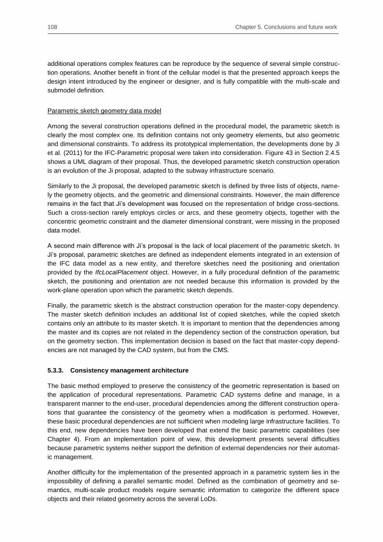
108 Chapter 5. Conclusions and future work
additional operations complex features can be reproduce by the sequence of several simple construc-
tion operations. Another benefit in front of the cellular model is that the presented approach keeps the
design intent introduced by the engineer or designer, and is fully compatible with the multi-scale and
submodel definition.
Parametric sketch geometry data model
Among the several construction operations defined in the procedural model, the parametric sketch is
clearly the most complex one. Its definition contains not only geometry elements, but also geometric
and dimensional constraints. To address its prototypical implementation, the developments done by Ji
et al. (2011) for the IFC-Parametric proposal were taken into consideration. Figure 43 in Section 2.4.5
shows a UML diagram of their proposal. Thus, the developed parametric sketch construction operation
is an evolution of the Ji proposal, adapted to the subway infrastructure scenario.
Similarly to the Ji proposal, the developed parametric sketch is defined by three lists of objects, name-
ly the geometry objects, and the geometric and dimensional constraints. However, the main difference
remains in the fact that Ji‘s development was focused on the representation of bridge cross-sections.
Such a cross-section rarely employs circles or arcs, and these geometry objects, together with the
concentric geometric constraint and the diameter dimensional constrant, were missing in the proposed
data model.
A second main difference with Ji‘s proposal is the lack of local placement of the parametric sketch. In
Ji‘s proposal, parametric sketches are defined as independent elements integrated in an extension of
the IFC data model as a new entity, and therefore sketches need the positioning and orientation
provided by the IfcLocalPlacement object. However, in a fully procedural definition of the parametric
sketch, the positioning and orientation are not needed because this information is provided by the
work-plane operation upon which the parametric sketch depends.
Finally, the parametric sketch is the abstract construction operation for the master-copy dependency.
The master sketch definition includes an additional list of copied sketches, while the copied sketch
contains only an attribute to its master sketch. It is important to mention that the dependencies among
the master and its copies are not related in the dependency section of the construction operation, but
on the geometry section. This implementation decision is based on the fact that master-copy depend-
encies are not managed by the CAD system, but from the CMS.
5.3.3. Consistency management architecture
The basic method employed to preserve the consistency of the geometric representation is based on
the application of procedural representations. Parametric CAD systems define and manage, in a
transparent manner to the end-user, procedural dependencies among the different construction opera-
tions that guarantee the consistency of the geometry when a modification is performed. However,
these basic procedural dependencies are not sufficient when modeling large infrastructure facilities. To
this end, new dependencies have been developed that extend the basic parametric capabilities (see
Chapter 4). From an implementation point of view, this development presents several difficulties
because parametric systems neither support the definition of external dependencies nor their automat-
ic management.
Another difficulty for the implementation of the presented approach in a parametric system lies in the
impossibility of defining a parallel semantic model. Defined as the combination of geometry and se-
mantics, multi-scale product models require semantic information to categorize the different space
objects and their related geometry across the several LoDs.
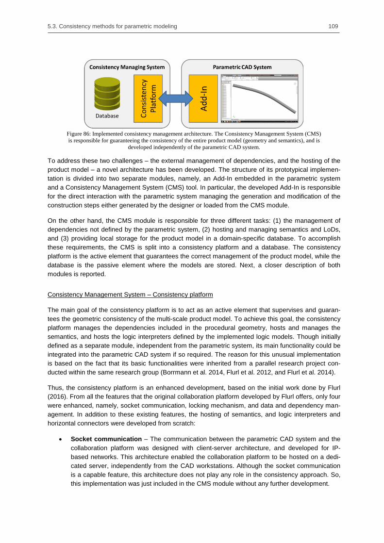
5.3. Consistency methods for parametric modeling 109
Figure 86: Implemented consistency management architecture. The Consistency Management System (CMS)
is responsible for guaranteeing the consistency of the entire product model (geometry and semantics), and is
developed independently of the parametric CAD system.
To address these two challenges – the external management of dependencies, and the hosting of the
product model – a novel architecture has been developed. The structure of its prototypical implemen-
tation is divided into two separate modules, namely, an Add-In embedded in the parametric system
and a Consistency Management System (CMS) tool. In particular, the developed Add-In is responsible
for the direct interaction with the parametric system managing the generation and modification of the
construction steps either generated by the designer or loaded from the CMS module.
On the other hand, the CMS module is responsible for three different tasks: (1) the management of
dependencies not defined by the parametric system, (2) hosting and managing semantics and LoDs,
and (3) providing local storage for the product model in a domain-specific database. To accomplish
these requirements, the CMS is split into a consistency platform and a database. The consistency
platform is the active element that guarantees the correct management of the product model, while the
database is the passive element where the models are stored. Next, a closer description of both
modules is reported.
Consistency Management System – Consistency platform
The main goal of the consistency platform is to act as an active element that supervises and guaran-
tees the geometric consistency of the multi-scale product model. To achieve this goal, the consistency
platform manages the dependencies included in the procedural geometry, hosts and manages the
semantics, and hosts the logic interpreters defined by the implemented logic models. Though initially
defined as a separate module, independent from the parametric system, its main functionality could be
integrated into the parametric CAD system if so required. The reason for this unusual implementation
is based on the fact that its basic functionalities were inherited from a parallel research project con-
ducted within the same research group (Borrmann et al. 2014, Flurl et al. 2012, and Flurl et al. 2014).
Thus, the consistency platform is an enhanced development, based on the initial work done by Flurl
(2016). From all the features that the original collaboration platform developed by Flurl offers, only four
were enhanced, namely, socket communication, locking mechanism, and data and dependency man-
agement. In addition to these existing features, the hosting of semantics, and logic interpreters and
horizontal connectors were developed from scratch:
Socket communication – The communication between the parametric CAD system and the
collaboration platform was designed with client-server architecture, and developed for IP-
based networks. This architecture enabled the collaboration platform to be hosted on a dedi-
cated server, independently from the CAD workstations. Although the socket communication
is a capable feature, this architecture does not play any role in the consistency approach. So,
this implementation was just included in the CMS module without any further development.

110 Chapter 5. Conclusions and future work
Locking mechanism –The main goal of the original collaboration platform was to consistently
manage geometric representations when several users access the same model at the same
time. To avoid inconsistencies due to simultaneous modification of the same geometry, the
collaboration server14
implemented the capability of locking specific construction operations on
specific CAD clients. This feature was extended to lock and refuse the manual modification of
construction operations created by logic models.
Data management – The presented multi-scale approach is based on the combination of
several neutral, procedural, and assembly models. To achieve this goal, the database linked
to the collaboration platform was extended to manage these three types of models. Figure 87
shows the project management tab on the user interface of the consistency platform.
Dependency management – Another main goal of the collaboration platform was to manage
the dependencies created outside of the parametric CAD system. This light-enhanced module
enables the consistency preservation of the geometric representation through several LoDs
and several submodels. Thus, any modification that the parametric system cannot manage,
such as a modification on a global parameter or a master-copy sketch, is recognized by this
module and updated in the geometry accordingly.
Hosting semantics – Hosting the semantic information parallel to the geometry plays a main
role in the multi-scale methodology. In particular, the semantic information is the only element
that describes which geometry is placed in each LoD, and without the hosting and managing
of this information, the parametric CAD system would receive the complete model without
knowing whether a construction operation must be displayed or not.
Logic interpreters and horizontal connectors – Since the hosting and management of the
logic interpreters and horizontal connectors is done in the consistency platform, the logic
models‘ implementation can profit from the existing locking mechanism and dependency man-
agement module.
Figure 87: Project management tab contained in the consistency platform user interface. On the left-hand
side, a list of procedural and assembly models for the different projects is referenced, while on the right-hand
side, the list of semantic spaces created for a space model is shown.
14
In the work done by Flurl et al. (2012, 2014) the terms Collaboration platform and Collaboration server are
equivalent and used as synonyms.

5.3. Consistency methods for parametric modeling 111
Consistency Management System – Database
The second module contained in the CMS is the domain-specific database. Inherited and enhanced
from an initial development by Flurl (2016), this passive element provides storage for the latest version
of each product model, i.e. the updated objects managed by the consistency platform overwrite the
existing ones in the database. Due to the large amount of objects that constitute a multi-scale product
model, the database was divided into several tables. This design additionally enables the direct ac-
cess to specific parts of the product model, such as logic models or semantic information, inde-
pendently during the modeling process.
Figure 88: Five main areas of the database: (1) the main area; (2) the assembly area; (3) the logic model area;
(4) the procedural model area; and (5) the semantics area.
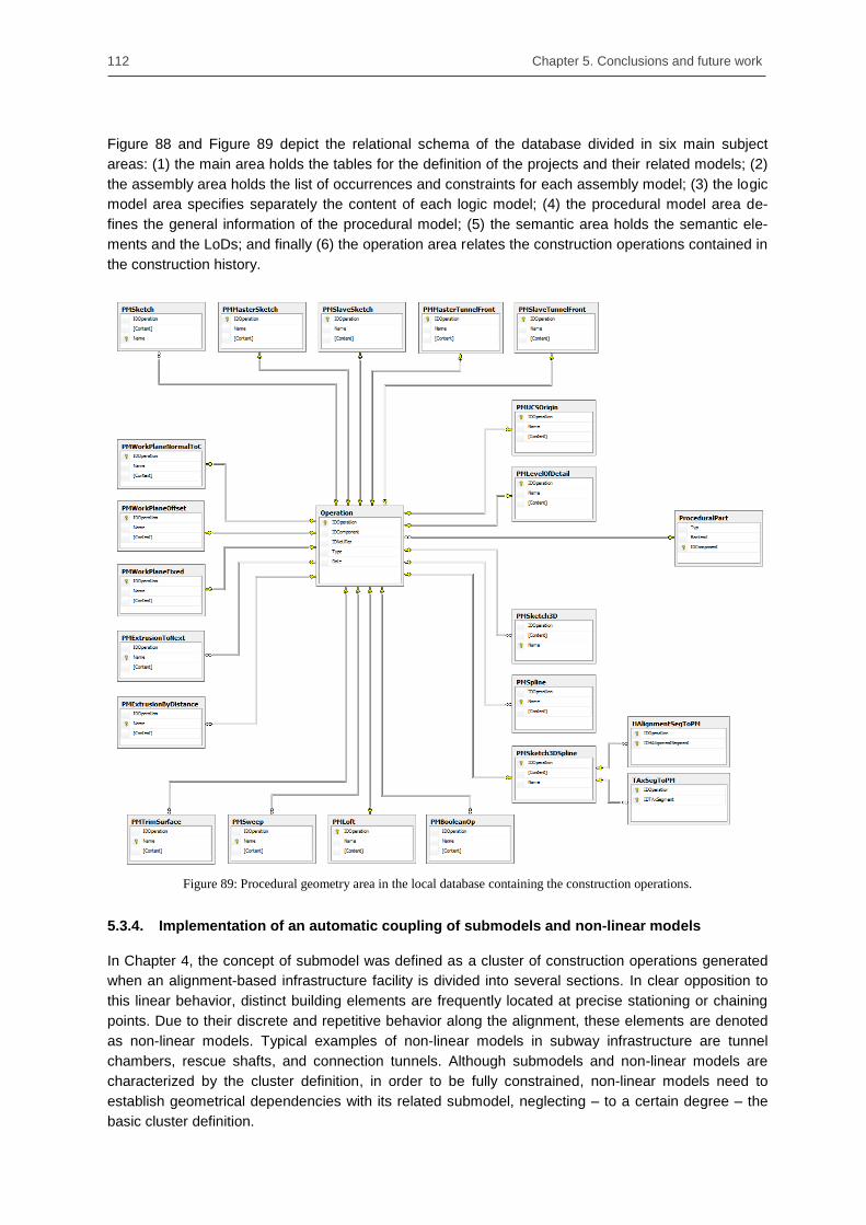
112 Chapter 5. Conclusions and future work
Figure 88 and Figure 89 depict the relational schema of the database divided in six main subject
areas: (1) the main area holds the tables for the definition of the projects and their related models; (2)
the assembly area holds the list of occurrences and constraints for each assembly model; (3) the logic
model area specifies separately the content of each logic model; (4) the procedural model area de-
fines the general information of the procedural model; (5) the semantic area holds the semantic ele-
ments and the LoDs; and finally (6) the operation area relates the construction operations contained in
the construction history.
Figure 89: Procedural geometry area in the local database containing the construction operations.
5.3.4. Implementation of an automatic coupling of submodels and non-linear models
In Chapter 4, the concept of submodel was defined as a cluster of construction operations generated
when an alignment-based infrastructure facility is divided into several sections. In clear opposition to
this linear behavior, distinct building elements are frequently located at precise stationing or chaining
points. Due to their discrete and repetitive behavior along the alignment, these elements are denoted
as non-linear models. Typical examples of non-linear models in subway infrastructure are tunnel
chambers, rescue shafts, and connection tunnels. Although submodels and non-linear models are
characterized by the cluster definition, in order to be fully constrained, non-linear models need to
establish geometrical dependencies with its related submodel, neglecting – to a certain degree – the
basic cluster definition.

5.3. Consistency methods for parametric modeling 113
In addition, the repeated integration of non-linear models into large infrastructure facilities presents two
main difficulties, namely, the renaming of the instantiated construction operations and the definition of
new procedural dependencies between the submodel and the non-linear model. To fulfill these de-
mands, Section 4.4 presented a three-step methodology where the two first steps add the semantic
information to the construction operations, and the third executes the integration algorithm.
During the first integration step, an attribute is added to all the construction operations that define the
non-linear model. This attribute can only be defined as auxiliary, connection, and geometry, depending
on its role during the integration process. In order to evaluate this methodology, a new user interface
was developed that allows designers and engineers to define and manage construction operations
based on this attribute. Figure 90 shows the mentioned interface.
Figure 90: User interface developed to define and manage construction operations based on its integration at-
tribute.
During the second integration step, pairs of construction operations must be defined. The idea behind
these pairs is to match equivalent construction operations in the submodel, and the non-linear model.
In the example depicted in Figure 92, the equivalent operations are the work-planes. In the linear
model, the work-plane indicates the stationing point in which the non-linear model must be introduced,
while in the non-linear model, the work-plane is the starting construction operation for defining the
axes of the rescue shaft.
Although this process can be automated in coarser LoDs based on the attribute defined in both mod-
els, in more detailed LoDs, with large amount of pairs to be matched, the mere existence of this attrib-
ute cannot guarantee the success of the matching process. However, this limitation has become the
starting point for a branched research topic with promising first results (Vilgertshofer & Borrmann
2015). Figure 91 shows the developed interface that allows designers and engineers to create these
construction operation pairs.

114 Chapter 5. Conclusions and future work
Figure 91: User interface developed to create pairs of construction operations.
During the third integration step, the integration algorithm presented in Section 4.4 is executed. To
illustrate this, Figure 92 presents the algorithm built upon an instantiated example.
5.4. Consistency methods based on logic models
5.4.1. Overview
The design of subway infrastructure facilities is firmly governed by guidelines, codes, and national and
international standards. Understanding and implementing the underlying abstract knowledge in a
parametric geometry is a non-trivial task. Moreover, experts should interpret the demands of such
engineering rules, match them to their specific requirements, and express their decisions in an appro-
priate geometric representation. In conclusion, the design task built upon engineering rules is time
consuming and impedes the search of innovative solutions based on what-if analyses.
To respond to this technological weakness, Section 4.5 presented a novel methodology that captures
the underlying design knowledge by means of distinct units known as logic models. In particular, each
logic model encapsulates an engineering rule, enabling both the automatic interpretation of abstract
input parameters, and the generation of a corresponding set of construction operations. Moreover, to
avoid the repetition of their input definition, several logic models are horizontally connected to create a
more complex modeling result. In this way, engineers and other experts can alter complete sections of
an infrastructure facility through the modification of parameters.
For evaluating the developed methodology, four logic models and three horizontal connectors were
developed. Each logic model and horizontal connector responds to a different design challenge,
ranging from the alignment description at LoD1, down to the ring design at LoD5. Finally, two different
integrations within the design workflow are shown, and their benefits and drawbacks are discussed.

5.4. Consistency methods based on logic models 115
Figure 92: The four integration steps built upon an instantiated example. In this particular infrastructure a
tunnel submodel and a rescue shaft are modelled in LoD1. (The arrows between construction operations only
represent their sequence in the construction history)

116 Chapter 5. Conclusions and future work
5.4.2. Alignment and tunnel axis models
The first two logic models are characterized by the similar output they generate, i.e. a set of spatial
curves that describe the course of the subway infrastructure in space. The first curve, defined in LoD1,
is created by the alignment model, and represents the curve midway between the rails. The second
curve, defined in LoD2, is created by the tunnel axis model, which shifts the resulting alignment curves
by vertical and horizontal parameters. Both logic models are explained in detail.
Alignment Model (AM)
The Alignment Model (AM) is responsible for converting the alignment information into a set of 3D
spline curves in the parametric CAD system. The alignment of a subway infrastructure represents the
curve midway between the two rails and is usually constructed by the superposition of two 2D curve
representations known as horizontal and vertical alignments. While the horizontal alignment is defined
by straight segments, arcs, and connection curves, the vertical alignment is only described by straight
lines and their interpolation curves at the intersection points, which generate the crest and sag curves.
The correct definition of the alignment‘s information is crucial in the design of a subway infrastructure,
not only because it is the fundamental geometry upon which the other LoDs rely, but also because it is
the basic information needed to define the submodel partition strategy. Often, two different strategies
are used to define this submodel partition, namely: based on a fixed number of horizontal alignment
segments, or based on a constant length along the stationing. For the implementation done in the AM,
and due to the fact that the submodel definition is an intrinsic characteristic not easily altered in a later
design stage, a partition equivalent in number to the divisions of the horizontal alignment has been
chosen. As a direct consequence, short tunnel tracks defined by a small number of horizontal align-
ment segments, generate a sufficient number of submodels capable of evaluating the proposed ap-
proach.
During the infrastructure design, the alignment‘s definition is the design start point, and the only se-
mantic object contained in LoD1. Unlike other horizontally connected logic models, the definition of the
AM is solely based on the engineer‘s design contribution. To capture it, the logic unit of the AM speci-
fies an alignment‘s data model that independently records the information of horizontal and vertical
alignment segments. These two types of segments are defined as abstract classes that share com-
mon properties with their inherited elements. Once instantiated, these elements are collected in two
separated lists and aggregated to the alignment model object. The resulting alignment data model is
depicted in Figure 93.
A primary difference between the two alignment curves is the method they implement for the linear
referencing. In particular, the horizontal alignment makes use of the stationing, while the vertical
alignment employs the chainage. The stationing, measured as flat projection of the alignment onto the
horizontal plane, yields an imprecise value of the global length. On the contrary, the chainage of the
vertical alignment, evaluated out of the stationing and elevation values, provides an exact magnitude
of the global length (Scarponcini 2002, ISO 2012). Despite the precise positioning of physical ele-
ments based on stationing values that involves measurement difficulties on the construction site, the
use of the stationing over the chainage is widely stablished. One reason for its usage is the small
gradient allowed for subway infrastructure, where the maximal values are typically under 4% (FGSV
1995, Lindamood et al. 2003, Schneider 2011), making stationing and chainage almost equivalent.

5.4. Consistency methods based on logic models 117
Figure 93: UML diagram of the logic unit defined by the alignment model.
Though the information required by the logic unit is intended to be manually entered by the designer,
for widespread engineering rules, this initializing information can be also extracted from neutral data
models. For the specific case of infrastructure alignments, several open standards provide such infor-
mation, e.g. LandXML, OKSTRA, and IFC-Alignment (Rebolj et al. 2008, Schultze and Buhmann
2008, and Amann et al. 2014a). To evaluate this possibility, a parser has been written that extracts the
needed information from an instantiated LandXML file and initializes the logic unit. This parsing capa-
bility is contained in one of the two modules in which the logic interpreter is divided.
Thus, the first module can extract any sequence of alignment segments provided by a LandXML file
and convert it into a set of B-spline operations. In order to generate the B-splines, pairs of horizontal
and vertical alignment segments are combined, generating a list of space points that are used to
define the through prescribed points of the B-spline curve (PICC 2012, Höllig and Hörner 2013). From
the different transition curves that can be defined between the straight and the curve segments in the
horizontal alignment, only the clothoid is taken into consideration.
The second module is responsible for updating the affected alignment segments after a parameter is
modified in the logic unit e.g., the A-constant of a clothoid or the radius of a curve. Specifically, this
module calculates the updated coordinates for the connection points of two consecutive alignment
segments. Contrary to the parser module, not all the sequences of alignment segments are supported
and only patterns LKCKL are identified and modified (Line-Clothoid-Curve-Clothoid-Line). Figure 94
depicts an example of such a LKCKL alignment pattern. Appendix C explains this algorithm in detail.
The recognition on this pattern enables three types of modifications:
Modification of the A-constant of one clothoid affects the segment itself and one predecessor
and one successor, namely the line and the curve neighboring the clothoid. This modification
is therefore classified as Grade 1.
Modification of the curve’s radius affects the segment itself and two predecessors and two
successors. This modification is classified as Grade 2.

118 Chapter 5. Conclusions and future work
Displacement of the curve’s PI. PI stands for Point of Intersection and is equivalent to the vir-
tual intersection of its two lines nearby. As these lines are connected at the same time to other
clothoids and curves, the amount of affected segments is large, and spans four predecessors
and four successors. This displacement is classified as Grade 4.
Figure 94: Alignment based on the pattern LKCKL; Line (in black) – Clothoid (in red) – Curve (in blue) –
Clothoid – Line. The description of the segments are done by the engineer or extracted from a neutral data
model. The connection points must be specified, while the inner points are calculated by the logic interpreter.
Tunnel axis model (TAM)
Building subway infrastructure is an expensive activity. Of the multiple aspects that affect its final
budget, the diameter of the tunnel is one of the most important. Every reduced centimeter affects,
among others, the required volume of concrete, and the fabrication expenses of the TBM. Therefore,
tunnel engineers try to reduce the diameter of the tunnel to its minimum. This reduction stops when
the clearance profile reserved for the train collides with the tunnel‘s construction tolerance. Although
this effect can be easily adjusted on straight segments, the consequence of a train tilting on a canted
curve may enforce the construction of a larger diameter for the complete tunnel. To overcome this
limitation on narrow curves, tunnel engineers introduce a horizontal shift between the tunnel axis and
the infrastructure alignment. This displacement generates an extra space that the clearance profile
can occupy. Figure 95 shows a clearance profile of a train tilting on a canted curve with and without
horizontal shifting.
Figure 95: Example of how the clearance profile of the train is affected by shifting the tunnel axis. On the left
the axis is not shifted and the clearance of the train overlaps the construction tolerance of the tunnel. On the
right, the axis has been shifted and both spaces do not overlap.
The main goal of the Tunnel Axis Model (TAM) is to provide tunnel engineers with a shifting tool for the
tunnel axis. In particular, the TAM allows engineers to assign an independent vertical and horizontal
shift parameter for every horizontal alignment segment. By default, the vertical shift parameter remains

5.4. Consistency methods based on logic models 119
constant along the tunnel, while the horizontal parameter can differ for each curve. The tunnel axis is
defined as an alignment equivalent curve, where the curve‘s radius is reduced along with the horizon-
tal shift parameter. A simple example is shown in Figure 96, where a section of a tunnel is represented
by its alignment and tunnel axis curves. In this example the TAM defines a shift parameter on the
curve alignment segment that creates an offset between both curves.
Figure 96: Tunnel section represented by its alignment (in black) and tunnel axis (in red) curves. The TAM
defines a vertical and horizontal shift. The vertical shift parameter is constant, while the horizontal one varies,
creating the desired tunnel axis offset.
For the implementation of the TAM‘s logic unit, a simple data model has been developed that contains
only two classes. So, a list of axis displacement entities is aggregated to the TAM main class. This list
is equivalent in number to the horizontal alignment segment list, and describes for each element the
corresponding shifting parameter. To initialize this logic model, a link to an alignment model is needed.
After the initialization process is finished, the tunnel engineer can introduce the shifting parameters to
the required curves.
Figure 97: UML diagram of the TAM’s logic unit and its access to the information contained in the alignment
model.
Once the logic unit is initialized or each time a shift parameter altered, the logic interpreter creates or
modifies the corresponding construction operations. Because the TAM is constructed on the basis of
the AM, any change introduced to the AM will additionally trigger an update in the outcome geometry
of the TAM. Figure 97 represents the UML diagram of the TAM logic unit, and its access to the infor-
mation contained in the alignment model.

120 Chapter 5. Conclusions and future work
5.4.3. Ring design and tunnel configurator models
In comparison to the AM and the TAM developed to evaluate the viability of logic models in the early
stages of design, the two logic models presented in this section address the need for engineering
rules in the detailing process, i.e. in LoD5. Thereby, the ring design model (RDM) assists engineers in
the definition of the main ring parameters, e.g. the inner and outer diameter, the length of the ring, and
the value of the conicity. In a similar way, the tunnel configurator model (RCM) profits from the infor-
mation defined in the RDM and the TAM to create a sequence of rings that minimizes its deviation
from the theoretical tunnel axis curve. Both logic models, their benefits and limitations, are explained in
detail.
Ring design model (RDM)
One widely accepted construction methodology for subway tunnels is based on the assembly of con-
secutive precast concrete rings. From the different typology of existing rings, the so-called universal
ring has proved especially successful (Guglielmetti et al 2008, Maidl et al 2011). Universal rings are
single tapered rings where the portal side surface is frequently not perpendicular to the ring axis. The
conicity created by this tapered surface enables the ring to follow the alignment definition. So, the
larger the conicity, the smaller the curvature of the feasible alignment. Figure 98 shows a universal
ring made up of seven ring segments. Notice that in this example the key stone is from the same size
as the other segments, in a configuration that is known as 7+0.
Figure 98: Universal ring made up of seven ring segments.
The logic unit of the Ring Design Model (RDM) is based on a single class that stores the parameters
introduced by the tunnel engineer. At this point it is important to mention that this logic model does not
pretend to analyze or simulate the new ring design based upon the boundary conditions, but to create
a geometric model that matches the information provided. To achieve this goal, four input parameters
have been defined in the logic unit:
Inner and outer diameter – These values must be inside of the range defined for the lining
space. The main reason these parameters are not directly extracted from the space infor-
mation is due to the tunnel construction tolerances, which are also included in the space defi-
nition, and that change for every single project.
Ring length – Fundamental parameter whose value can only be defined by experience, or
heuristics. On the one hand, short rings allow tunnel engineers to follow alignments more ex-
actly, and to build tunnels with smaller curves. On the other hand, the time to erect a ring is

5.4. Consistency methods based on logic models 121
independent of its length and therefore longer rings enable shorter construction schedules
(BTS & ICE 2004).
Conicity – Although the conicity parameter can be calculated from the alignment information,
tunnel engineers use a smaller curve radius to allow TBM operators to return to the theoretical
trajectory when a deviation appears at the construction site (Guglielmetti et al 2008).
Number of segments – The number of segments is directly related to the tunnel‘s diameter.
So, a smaller number of segments produces faster building ratios, but increases the weight of
each segment. Increasing the weight of segments is not only a limitation that some TMB ma-
chines cannot handle, but poses a potential risk of rings collapsing when the building is not yet
complete.
Once the engineer has introduced the complete information to the logic unit, the logic interpreter
modifies an existing assembly ring model to adapt the geometric model to the information committed.
From the experience gained through the evaluation of this logic model, it can be said that using a
single assembly ring model where all the parameters are applied is a difficult task to meet. Specifically,
the modification of the number of segments in a ring requires a costly modification to the assembly
that is not required for parameters such as the conicity or the length of the ring. Therefore, it is rec-
ommended that logic models for detailed LoD make use of a combined approach based on several
pre-defined topic-related models and parametric modifications.
Tunnel configurator model (TCM)
One of the challenges engineers have to solve when constructing a shield tunnel is the calculation of
the rotation angle for each ring along the axis. As the axis of the ring is straight, the combination of
rings approximates the theoretical tunnel axis using a polygonal curve. Figure 99 shows an example of
a straight tunnel made up of five universal rings. Even in this simple example, and due to the ring‘s
conicity, the sequential combination of rings is unable to exactly follow the tunnel axis. Therefore, an
optimization process is needed in the logic interpreter that minimizes the deviation of the polygonal
curve created by the selected combination of rings from the theoretical tunnel axis.
Figure 99: Example of a simple tunnel made up of five rings. The tunnel axis (dashed line) is approximated
by the combination of rings, creating a polygonal tunnel axis (red line)
An additional difficulty for this optimization process is the fact that rings can only be erected in a limited
number of positions. First, the number of feasible positions is usually directly related to the amount of
pressure jacks on the TBM. For universal rings, these are frequently two or three positions, equally
distanced, per segment. Secondly, from the feasible number of positions, some of them are excluded
from the optimization analysis, because two adjacent rings cannot have their longitudinal joints
aligned. This avoids cross-joints, which are the most common location for leaks in tunnels (Maidl et al.
2013).

122 Chapter 5. Conclusions and future work
Figure 100: Example of a tunnel section created by the TCM, where 110 rings were combined.
The logic unit of the TCM allows the tunnel engineer to define, additionally to the already explained
restrictions, some initialization parameters for the optimization process, such as the number of jacks
per segment, the angle for the positioning of the first key-stone, and if needed, the angles of the lock
sector. This lock sector is defined by contractors who want to avoid the risk of installing rings with the
key-stone at the bottom of the ring. Once this information is introduced, the logic interpreter launches a
new optimization process together with the definition of the ring (RDM) and the tunnel axis (TAM).
The optimization algorithm is placed in the logic interpreter, and its main goal is to minimize the devia-
tion of the polygonal axis created by the selected combination of rings from the theoretical tunnel axis
curve. For the prototypical implementation of this optimization problem, the algorithm described by
Socher (2013) has been used, which provides reliable results for short tunnels. Figure 100 shows the
result of this optimization algorithm for a 300-meter radius curved tunnel and 110 rings.
The geometric layer receives the result of this optimization algorithm as an assembly model. In this
assembly model, the constraints and rotation parameters are defined in a neutral manner, which the
geometry layer must convert into a proprietary outcome. For the complete representation of the as-
sembly tunnel, only three types of constraints have been defined, from which only the angle between
axes defines a parameter. This minimal implementation shows how effective the combination of pro-
cedural and assembly modeling for the description of infrastructure facilities can be.
5.4.4. Horizontal connectors
As the design of an infrastructure facility evolves, the underlying knowledge becomes more complex.
To avoid redundancy in the definition of logic models but at the same time, reducing its developing
effort, several models can be connected horizontally (see Section 4.5.4). These horizontal connectors
allow logic models to initialize themselves with the current information contained in dependent models,
and to be notified each time a modification arises in one of these models.
To evaluate the modeling approach based upon logic models, three horizontal connectors have been
developed. These connectors are defined by a single letter and are defined as follows:
The connector Track (T) links the alignment and the tunnel axis models. In addition to the up-
date events of the active connection, the track connection makes the horizontal alignment de-
scription, and its neutral procedural operations available to any logic model that implements
the sink-plug.
The connector Axis (A) links the tunnel axis and tunnel configurator models. An additional ap-
plication of the axis connector, not covered in this case study, links the tunnel axis with the

5.4. Consistency methods based on logic models 123
ring design model. If so, the ring‘s conicity parameter, defined as a fixed value in the ring de-
sign, could be dynamically updated with any modification to the alignment model.
The connector Ring (R) links the ring design and tunnel configurator models. This connector
communicates the ring parameters defined in its logic unit.
The integration of horizontal connectors with logic models has been successfully accomplished with a
simple tunnel case study. Due to the limitations of the optimization algorithm (Socher 2013) that runs
as a part of the TCM, this case study is independent of the real-world case study presented in Section
5.5. For this case study, a shorter tunnel, about 300 meters long, was selected. Besides this limitation,
the same design parameters and the same universal ring of the real case study were employed. The
final combination of logic models and horizontal connectors is depicted in a logic model diagram
(LMD) represented in Figure 101.
Figure 101: Logic Model Diagram (LMD) for the tunnel case study, where the four logic models and the
three horizontal connectors have been applied.
5.4.5. Integration of logic models into the infrastructure design workflow
In order to achieve a successful adoption of the logic model design methodology, its integration into
the engineer‘s workflow is conditional. This integration must guarantee the consistency of the product
model, enabling the coexistence of conventional and logic model approaches. Finally, the integration
of new interfaces has to be performed in a natural and seamless manner from the user perspective.
Two restrictions were identified in order to guarantee the consistency of the procedural model when
new construction operations are introduced by logic models. First, construction operations generated
by logic models must be introduced in the procedural model at the end of the construction history,
independently of their LoD and submodel. This approach avoids inconsistencies arising from reverse
dependencies between construction operations, i.e. referenced construction operations are placed
earlier in the construction history than the referencing operations. Secondly, the logic model‘s input
must be based either on the abstract information introduced by the engineer or on the geometry
resulting from other logic models. This restriction avoids the need for interpreting the content of a
parametric sketch or the sequence of several construction operations. Therefore, as the construction
operations generated by logic models are native operations of the CAD system, every subsequent
modeling step built upon these operations will be consistently updated by the parametric CAD system.
This fact assures the total integration of the logic model outcome into the procedural models.
To illustrate the workflow combining manual modeling and logic models, Figure 102 shows an exam-
ple of a tunnel model up to LoD3. The workflow begins with the definition of the alignment of the
subway infrastructure. To perform this modeling step, the designer imports the alignment information
directly from a LandXML file. Once the alignment is converted into a set of 3D splines by the AM, the
definition of the tunnel axis can be generated. To achieve this, the TAM provides a user interface

124 Chapter 5. Conclusions and future work
where the value of the horizontal parameter can be defined separately for each curve. At this modeling
point, the designer can carry on with the detailing process using the parametric system as usual,
regardless of the logic model extension. Next, at the time of constructing the lining of the tunnel, the
designer only needs to fill in the information requested by the user interface of the RDM and RCM.
Completion of this step generates, the tunnel‘s lining automatically. Finally, to avoid inconsistencies in
the generated geometry, logic models lock their construction operations from manual manipulation.
However, the interfaces defined by each logic models can be always reopened and its abstract infor-
mation revised to complete a rapid and consistent modification of the final geometry.
Figure 102: Workflow followed to model a tunnel. On the left, the dependency diagram of the procedural ge-
ometry model, and on the right, the workflow the engineer follows to model the complete model. For demon-
stration purposes the workflow is extended beyond LoD3 until LoD5.
The logic units are the elements responsible for interfacing with the designer. The integration of these
new interfaces into the design workflow is key to their successful adoption. Therefore, two different
integration strategies have been adopted: directly into the CAD system as a set of advanced features;
and joined in a domain-specific editor. Both methodologies are explained in detail below.
Integration of logic models as advanced features
The literature and practical experience show that CAD users prefer to work with feature-based sys-
tems rather than with the direct manipulation of surface geometries (Regli et al., 2000; Bidarra, 1999).
In parametric CAD systems, the non-sketch-based procedural operations described in Section 2.3.1
usually follows this feature approach, where users only introduce the semantic information of the
geometry they want to create or modify, while the CAD system manipulates the geometry and estab-
lishes the necessary dependencies. Figure 103 shows an example of a graphical user interface for the
hole-feature in Autodesk Inventor. In this feature interface, the user can define not only the placement
and size of the hole, but also semantic information such as the type of the hole or the angle of the drill
point.

5.4. Consistency methods based on logic models 125
Figure 103: Hole-feature interface in Autodesk Inventor.
Following this feature interface methodology, the logic units can be introduced in the parametric sys-
tem as a new set of advanced domain-specific feature interfaces. To achieve this goal, the basic
architecture described in Section 5.3.3 was extended, allocating as many new advanced features as
developed logic models. Specifically, the developed Add-In module includes the logic units and the
geometric layers, while the consistency platform in the CMS includes the logic interpreters. The work-
flow associated with this approach begins with the parametric CAD system, where the engineer se-
lects the logic models of his interest. After introducing all the information in the advanced feature, the
content of the logic unit is sent to the CMS where the logic interpreter analyzes and generates a set of
neutral construction operations. Finally, these operations are sent back to the parametric system
where the geometric layer translates and incorporates them as new proprietary construction opera-
tions. Figure 104 depicts the mentioned extension of the basic architecture.
Figure 104: Extension of the basic architecture to incorporate the use of logic models as advanced features.

126 Chapter 5. Conclusions and future work
Integration of logic models in a domain-specific editor
The approach built upon advanced features presents a minor weakness, i.e. the broad picture needed
for the infrastructure design cannot be recognized at first sight. The different pieces of knowledge are
spread under several advanced features and hidden from the infrastructure experts‘ sight through the
different LoD. Therefore, a second approach to integrate the logic model methodology is based on the
incorporation of all the different logic models into a single domain-specific editor. This approach allows
engineers and experts not only to manage all the knowledge information form a central tool, but also
to introduce modifications to the applied knowledge.
The architecture needed to integrate an editor is slightly different compared to the one used in the
advanced features approach. Although the logic interpreter remains in the CMS, and the geometry
layer in the CAD system, the logic units are collected in the editor. Figure 105 depicts the extension of
the basic architecture to incorporate the use of a domain-specific editor. The design workflow is also
changing and under this methodology the engineer enters all the required knowledge into the editor.
After the changes are committed, the content of the logic units is sent to the CMS where they are
analyzed by the logical interpreters, which as in the advanced features method, send the neutral
construction operations to the geometrical layer placed on the CAD system.
Figure 105: Extension of the basic architecture to incorporate the centralized use of logic models in a domain-
specific editor.
In summary, the integration of logic models as advanced features seems to be an approach that better
suits the workflow and expertise from infrastructure designers, where every design step is achieved by
a specific feature. On the other side, the integration of logic models in a domain-specific editor seems
to better match the needs of engineers, who may be interested in a broader picture spanning several
logic models.
5.4.6. Measuring efficiency gains
Finding a metric that enables a suitable comparison between the logic model approach and conven-
tional modeling techniques is a difficult issue. First, there is a software implementation effort, that due
to the complexity in the development of a logic model, an average engineer cannot undertake alone.
So, a close collaboration between civil engineers and software developers is expected in order to
successfully achieve their development.

5.5. Case study 127
Once this software implementation is done, the CAD users can integrate logic models into their work-
flow as they would do with any other feature of the parametric CAD system. To test how much time is
saved during the design stage with every design‘s iteration, two experiments were performed: First, a
tunnel section containing 110 rings was selected, resulting in a total length of 150 meters. The time
required by the TCM logic model to generate the model was about 25 seconds, while the manual
assembly took an advanced Autodesk Inventor user almost two hours (1h 57min). Secondly, the
alignment of this tunnel section was modified by implementing a standard what-if analysis: More
precisely, the radius of a curve was changed from 200 meters to 300 meters. This modification implied
the update of the rotation parameter of 80 tunnel rings. Undertaking these changes manually took the
advanced Inventor modeler almost 10 minutes (9 min 23 sec), while the logic model was performed
almost instantaneously.
In conclusion, the employment of logic models and parametric CAD systems enabled the modeling of
this complex case study in a short time and with little effort. Moreover, the resulting parametric model
was extremely flexible, i.e. the modification of one parameter, as the curvature radius of a horizontal
alignment segment, consistently updated the complete tunnel model.
5.5. Case study
5.5.1. Second main suburban track in Munich, Germany
To prove the feasibility of the multi-scale design approach for subway infrastructure facilities, the
different consistency methodologies developed during this thesis were applied on the modeling of a
subway tunnel that is about to be constructed in the city of Munich, Germany. This infrastructure
project, called the second main suburban track, has been designed to increase the limited capacity of
the actual main track, and to provide a faster connection between the two ends of the city (Deutsche
Bahn 2016a).
The proposals for a second main track were initially discussed in the mid 90‘s after the estimations of
250.000 passengers per day were clearly exceeded. However, and because the huge challenge such
infrastructure facilities represent, the first measure was to increase the number of trains on the track;
setting a frequency of two minutes between trains and making the first main track in Munich one of the
most dense tracks in Germany (Deutsche Bahn 2016b). Despite the augmented capacity more trains
introduced, the continuous growing, which reached more than 800.000 passengers in recent years,
led authorities to decide for the construction of the second main track. Hence, in the late 2000‘s the
planning stage began.
The newly designed infrastructure facility is a nine-kilometer twin-tunnel railway track, with more than
seven kilometers running underground. To avoid collisions with existing transportation networks the
tunnels are planned 40 meters beneath the city‘s surface. This requirement, together with the length of
each tunnel section – only three stops are planned within the city center – make the construction of
nine rescue shafts necessary to allow passengers to safely leave the tunnel in case of emergency.
Finally, an underground turnout is designed for a future, not yet planned, south branch.
The early design phases (HOAI Leistungsphase 2-4) were carried by the engineering office Obermey-
er Planen + Beraten. The resulting 2D drawings provided the basis for the product modelling efforts
conducted in the frame of this case study. The detailed design phase is currently underway. Altogeth-
er, this infrastructure facility is a highly challenging and dynamic project and the perfect testing scenar-
io for the proposed methodology.
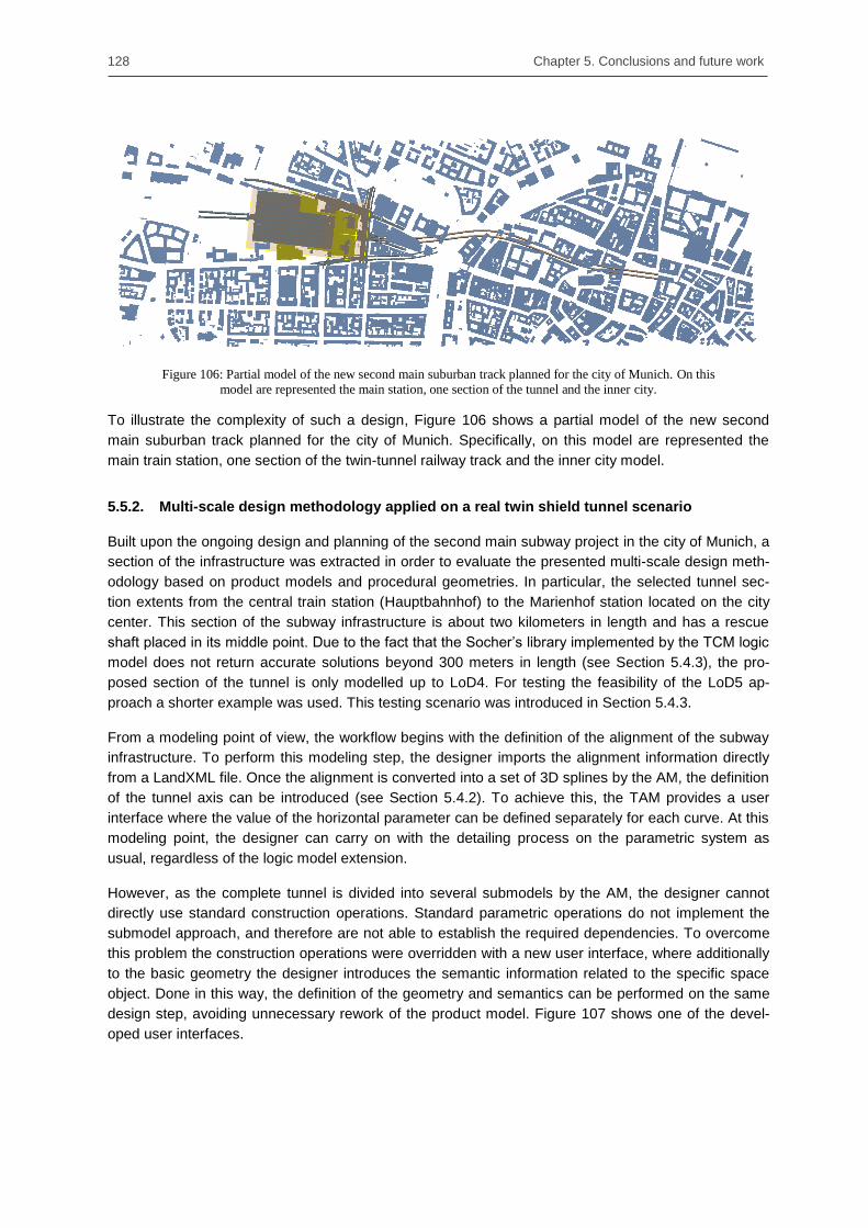
128 Chapter 5. Conclusions and future work
Figure 106: Partial model of the new second main suburban track planned for the city of Munich. On this
model are represented the main station, one section of the tunnel and the inner city.
To illustrate the complexity of such a design, Figure 106 shows a partial model of the new second
main suburban track planned for the city of Munich. Specifically, on this model are represented the
main train station, one section of the twin-tunnel railway track and the inner city model.
5.5.2. Multi-scale design methodology applied on a real twin shield tunnel scenario
Built upon the ongoing design and planning of the second main subway project in the city of Munich, a
section of the infrastructure was extracted in order to evaluate the presented multi-scale design meth-
odology based on product models and procedural geometries. In particular, the selected tunnel sec-
tion extents from the central train station (Hauptbahnhof) to the Marienhof station located on the city
center. This section of the subway infrastructure is about two kilometers in length and has a rescue
shaft placed in its middle point. Due to the fact that the Socher‘s library implemented by the TCM logic
model does not return accurate solutions beyond 300 meters in length (see Section 5.4.3), the pro-
posed section of the tunnel is only modelled up to LoD4. For testing the feasibility of the LoD5 ap-
proach a shorter example was used. This testing scenario was introduced in Section 5.4.3.
From a modeling point of view, the workflow begins with the definition of the alignment of the subway
infrastructure. To perform this modeling step, the designer imports the alignment information directly
from a LandXML file. Once the alignment is converted into a set of 3D splines by the AM, the definition
of the tunnel axis can be introduced (see Section 5.4.2). To achieve this, the TAM provides a user
interface where the value of the horizontal parameter can be defined separately for each curve. At this
modeling point, the designer can carry on with the detailing process on the parametric system as
usual, regardless of the logic model extension.
However, as the complete tunnel is divided into several submodels by the AM, the designer cannot
directly use standard construction operations. Standard parametric operations do not implement the
submodel approach, and therefore are not able to establish the required dependencies. To overcome
this problem the construction operations were overridden with a new user interface, where additionally
to the basic geometry the designer introduces the semantic information related to the specific space
object. Done in this way, the definition of the geometry and semantics can be performed on the same
design step, avoiding unnecessary rework of the product model. Figure 107 shows one of the devel-
oped user interfaces.

5.5. Case study 129
Figure 107: Interface developed to integrate the semantic and the geometry definition under the same design
step. This interface enables also the automatic definition of submodel dependencies.
Finally, to complete the design of the proposed tunnel section, a rescue shaft is placed in its middle
stationing point. Since there is not yet any semantic definition for such infrastructure elements, during
the evaluation of the proposed approach only a geometric model was developed. After the definition of
the connection tags required for its automatic integration, the developed algorithm initializes and
introduces a copy of the procedural operations (see Section 4.4.4). The resulting tunnel section is
depicted in Figure 108.
After the modeling was completed, the original design can be easily modified to analyze several what-
if scenarios. On the one hand, each logic model can be reopened and its abstract information revised
at all times to complete a rapid and consistent modification of the geometry. On the other hand, mas-
ter-copy dependencies (see Section 4.4.3) are built upon standard parametric sketches that can be
modified in the same way any other conventional construction operation.
Figure 108: Tunnel section and rescue shaft of the second main suburban track between the central train sta-
tion (Hauptbahnhof) and the Marienhof station

130 Chapter 5. Conclusions and future work
The study could show that the use of logic models, submodel dependencies, and conventional con-
struction operations integrated within multi-scale product models enables flexible designs that can be
consistently modified almost instantaneously.
5.6. Summary
This chapter has verified the different consistency preservation methodologies presented in this thesis.
First, the several consistency preservation methods introduced in Chapter 3 and Chapter 4 were
implemented in a proof of concept effort. Secondly, the developed methods were applied and evaluat-
ed in a real case study based on the Second main suburban track, which is about to be constructed in
the city of Munich, Germany.
For the proof of concept of the several consistency preservation methods, three different tasks were
conducted. First, a multi-scale semantic model was developed. This conceptual model was prototypi-
cally implemented on the basis of an established exchange standard, the well-known IFC, and on the
basis of an ad-hoc XML data format. This second implementation additionally provided the possibility
of integrating semantics and geometry in a common product model. The remaining two tasks were
implemented in a commercial parametric system, the software Autodesk Inventor. Profiting from its
API, several extensions were developed that enhanced its basic functionality with the new procedural
dependencies and logic models.
Finally, these novel methodologies were successfully applied to a real subway infrastructure project.
Starting from its basic alignment definition, the flexible combination of the different methods enabled
the highly detailed modeling of a complete tunnel section. Moreover, during the modeling of this pro-
ject, several modifications were performed at different LoDs, showing that this approach is feasible for
the reliable and consistent modification of multi-scale models created during the design infrastructure
projects.

131
Chapter 6. Conclusions and future work
6.1. Concluding remarks
A central component in the digital design of infrastructure projects is Building Information Modeling
(BIM). As reported by the British Infrastructure and Projects Authority (2016), if properly implemented,
BIM technologies can reduce the design and construction costs of an infrastructure project up to 15%.
Similarly, BIM methodologies contribute to reducing construction delays, improving relationships
throughout the supply chain, and boosting innovation.
One of the key features of BIM is the use of 3D geometric representations as a basic element from
which the 2D drawings are derived. However, single 3D models can hardly encompass all the levels of
abstraction that different engineering disciplines are used to. Therefore, during the research conduct-
ed for this thesis, novel methodologies have been examined that resulted in the development of a
proposal for an IFC schema for shield tunnel infrastructure projects. Moreover, the widely accepted
concept of Levels of Detail (LoD) in Geographic Information Systems (GIS) has been integrated and
adapted to the specific requirements of infrastructure design. Although the proposed IFC extension is
specific for shield tunnels, the basic multi-scale approach is general and widely applicable.
The adoption of a multi-scale approach during the design of large infrastructure facilities presents clear
advantages, but also risks and challenges. The main difficulty resides in the consistency preservation
of the geometry across several LoD when a modification is performed. To address this issue, this
thesis developed several methods to preserve the consistency. Based on the use of well-known para-
metric CAD systems and new developed geometric dependencies, procedural geometries and as-
sembly structures give designers and engineers the flexibility of working independently on different
LoD, while the CAD system keeps the consistency of the complete model.
6.2. Research contributions
The research presented in this thesis aims at finding new methodologies to overcome the two main
challenges that emerge during the design of large infrastructure facilities, namely, the difficulties with
the exchange of planning information between engineering teams, and the lack of automated con-
sistency methods required when working in different levels of detail.
To address these challenges, this thesis provided three major contributions:
A new multi-scale product model was built upon the concepts of product models and multi-
scale data models to respond to the current limitations of both technologies.
Due to the clear separation product models establish between semantics and geometry,
methods based on parametric technologies have been developed that are capable to realize
the desired cross-LoD consistency preservation.

132 Chapter 6. Conclusions and future work
In addition to the basic design intent that can be captured by parametric sketches, a novel
methodology was developed, which allows designers and engineers to encapsulate the design
rationale when planning subway infrastructure facilities built upon codes, guidelines, and na-
tional standards.
To respond to the first aforementioned challenge, Chapter 3 presented a multi-scale product model for
shield tunnels that provides a complete representation of the semantic structure throughout five LoD.
A comprehensive analysis and decomposition of the tunnel structure was provided, which defines and
distributes in a spatial hierarchy the different spaces and physical objects that typically shape a shield
tunnel. More specifically, the hierarchical structure of spaces is composed across the four initial LoD,
while the entire set of physical objects are handled by the finest LoD5. This hierarchical structure is
realized by the definition of two new aggregation entities. Thus, combining these two entities enables
not only the definition of refinement relationships across different LoDs, but also the exclusive and
direct access of an object located at a specific LoD.
To contribute to solving the geometric consistency limitations current product models involve, this
thesis successfully introduced the integration of parametric technologies. Accordingly, Chapter 4
started with the investigation of the two main sources of inconsistency that arise when planning large
infrastructure facilities, namely, the cross-LoD and cross-submodel consistency problems. Contrary to
what might be initially expected, these two different types of model subdivisions enable the flexible
integration and combination of procedural and assembly representations. Thus, procedural models
were applied to space and physical objects, while assemblies were employed for the hierarchical
structure definition in LoD5. In addition, several dependency methods were developed that extend the
basic procedural consistency system and that enable the consistent update of the complete model
when a local modification is performed. Moreover, the submodel approach combined with the devel-
oped consistency methods enables the flexible and dynamic integration of non-linear models, such as
rescue shafts, connection tunnels and tunnel chambers.
Finally, also in Chapter 4, a novel methodology that enables the capture of the design rationale by
means of distinct units known as logic models was presented. These units, defined as autonomous
systems, assist designers and engineers in the automatic generation of geometry and dependencies
needed to render the requirements of an engineering rule. Moreover, to avoid repetition of the design
rationale, several logic models were horizontally connected to create a more complex modeling ap-
proach. In this way, engineers and experts can alter complete sections of an infrastructure facility by
the modification of distinct parameters, and visualize the resulting geometry almost instantaneously.
6.3. Limitations and future work
Although the methodologies developed and implemented in the frame of this thesis are generic and
widely applicable, the base technologies on which they rely on make further investigations necessary.
One example of this situation can be found in the IFC standard. Although it is just a matter of time
before the BuildingSmart organization adopts a multi-scale approach, the integration of parametric
technologies is not a minor topic that can be left unattended. In this direction the standardization
efforts made by the STEP standard are certainly a good starting point.
Parallel to these geometric difficulties, the presented approach is based on pure procedural represen-
tations, i.e., the geometry is solely described by its construction operations without any reference to its
generated explicit representation. During the design of tunnel spaces, this limitation does not repre-
sent a real drawback due to the fact that tunnel spaces are defined by simple geometry that encom-
passes the set of physical objects. However, this limitation becomes more evident when the detail of

6.3. Limitations and future work 133
the model increases, mainly in LoD5. So for the design of physical components, engineers need to
define cross-references between the procedural operation and the explicit geometry at a specific point.
Though the challenge of keeping the consistency of dual representations is a well-known issue called
persistent naming problem (Marcheix & Pierra 2002, Bidarra and Bronsvoort 2002), neither the STEP
standard nor the IFC product model describe methods to consistently address this problem. While it is
true that this persistency problem has been traditionally left to CAD vendors, the definition of new
consistency methodologies that integrate dual models also require further investigations.
Finally, the analysis done for the proof of concept identified one essential limitation of the logic model
approach: the implementation of logic models in LoD5 became an extremely laborious and time-
consuming task. However, this work can be significantly reduced by the integration of dynamic CAD
templates that the logic interpreter can handle and modify. Thus, modelled by design experts, dynamic
templates have the ability to adapt themselves in a predefined scenario, following conventional pa-
rameterization techniques. As a consequence, logic interpreters only need to manage a limited
amount of parameters, which in turn accelerates the deployment of new logic models. Actually, this
approach was already studied and implemented for the design and optimization of aircraft components
by LaRocca (2011) and Amadori et al. (2012). Thereby, one topic for future research could be the
merging of both approaches – logic models and dynamic CAD templates – to create a more flexible
and agile method to design large infrastructure facilities.


Bibliography 135
Bibliography
Amadori, K., Tarkian, M., Ölvander, J. & Krus, P. (2012). Flexible and robust CAD models for design
automation. Advanced Engineering Informatics, 26(2), pp.180–195.
Amann, J., Borrmann, A., Hegemann, F., Jubierre, J. R., Flurl, M., Koch, C., & König, M. (2013). A
refined product model for shield tunnels based on a generalized approach for alignment
representation. In: Proc. of the ICCBEI, Tokyo, Japan.
Amann, J., Flurl, M., Jubierre, J. R., & Borrmann, A. (2014a). An Approach to Describe Arbitrary
Transition Curves in an IFC Based Alignment Product Data Model. In: Proc. of the ICCCBE,
Orlando, USA.
Amann, J., Jubierre, J. R., Borrmann, A., & Flurl, M. (2014b). An alignment meta-model for the
comparison of alignment product models. eWork and eBusiness in Architecture, Engineering and
Construction. In: Proc. of the ECPPM, Vienna, Austria.
Amann, J., Singer, D., & Borrmann, A. (2015). Extension of the upcoming IFC alignment standard with
cross sections for road design, In: Proc. of the ICCBEI, Tokyo, Japan.
Amann, J., & Borrmann, A. (2015). Creating a 3D-BIM-compliant road design based on IFC alignment
originating from an OKSTRA-accordant 2D road design using the TUM Open Infra Platform and the
OKSTRA class library. Technical Report, Technische Universität München.
Anderl, R., & Mendgen, R. (1996). Modeling with constraints: theoretical foundation and application.
Computer-Aided Design, 28(3), 155-168
Bailey, I., Dandashi, F., Ang, H., & Hardy, D. (2004). Using Systems Engineering Standards In an
Architecture Framework. White paper eurostep company.
Bakkeren, W., & Tolman, F. P. (1994). Integrated structural engineering: is product modeling the way
to go?. In Bridging the Generations (pp. 39-44).
Baumann, R. (2004). Structure-Oriented Exchange of Product Model Data. Doctoral Dissertation.
Technische Universität Berlin.
Benner, J., Geiger, A., Gröger, G., Häfele, K. H., & Löwner, M. O. (2013). Enhanced LOD concepts for
virtual 3D city models. In ISPRS annals of the photogrammetry, remote sensing and spatial
information sciences. In Proc of the ISPRS 8th 3D GeoInfo conference & WG II/2 workshop (pp.
51-61).
Bettig, B., & Shah, J. (2001). Derivation of a standard set of geometric constraints for parametric
modeling and data exchange. Computer-Aided Design, 33(1), 17-33
Bettig, B., & Hoffmann, C. M. (2011). Geometric constraint solving in parametric computer-aided
design. Journal of computing and information science in engineering, 11(2), 021001
136
Bidarra, R., de Kraker, K. J., & Bronsvoort, W. F. (1998). Representation and management of feature
information in a cellular model. Computer-Aided Design, 30(4), 301-313.
Bidarra, R. (1999). Validity maintenance in semantic feature modeling. Doctoral Dissertations. TU Delft
Bidarra, R., & Bronsvoort, W. F. (2002). Persistent naming through persistent entities. In Proc.
Geometric Modeling and Processing (pp. 233-240). IEEE.
Bidarra, R., Nyirenda, P. J., & Bronsvoort, W. F. (2005). A feature-based solution to the persistent
naming problem. Computer-Aided Design and Applications, 2(1-4), 517-526
Biljecki, F., Zhao, J., Stoter, J., & Ledoux, H. (2013). Revisiting the concept of Level of Detail in 3D
City Modeling. ISPRS Annals of Photogrammetry, Remote Sensing and Spatial Information
Sciences, II-2/W1(November), 63–74. http://doi.org/10.5194/isprsannals-II-2-W1-63-2013
Björk, B. C. (1995). Requirements and information structures for building product data models. VTT
Technical Research Centre of Finland.
Bodein, Y., Rose, B., & Caillaud, E. (2014). Explicit reference modeling methodology in parametric
CAD system. Computers in Industry, 65(1), 136-147
Boeykens, S. (2012). Bridging building information modeling and parametric design. eWork and
eBusiness in Architecture, Engineering and Construction: In: Proc. of the ECPPM, Reykjavik, Ice-
land.
Borrmann, A., Ji, Y., & Jubierre, J. R. (2012). Multi-scale geometry in civil engineering models:
Consistency preservation through procedural representations. In: Proc. of the ICCCBE, Moscow,
Russia.
Borrmann, A., & Jubierre, J.R. (2013). A multi-scale tunnel product model providing coherent geometry
and semantics. In Proc. of the 2013 ASCE International Workshop on Computing in Civil
Engineering, Los Angeles, CA, USA.
Borrmann, A., Flurl, M., Jubierre, J. R., Mundani, R. P., & Rank, E. (2014). Synchronous collaborative
tunnel design based on consistency-preserving multi-scale models. Advanced Engineering
Informatics, 28(4), 499-517.
Borrmann, A., Kolbe, T. H., Donaubauer, A., Steuer, H., Jubierre, J. R., & Flurl, M. (2015a). Multi‐scale
geometric‐semantic modeling of shield tunnels for GIS and BIM applications. Computer‐Aided Civil
and Infrastructure Engineering, 30(4), 263-281
Borrmann, A., König, M., Koch, C., & Beetz, J. (Eds.). (2015b). Building Information Modeling:
Technologische Grundlagen und industrielle Praxis. Springer-Verlag.
Bourjault, A. (1984). Contribution à une approche méthodologique de l'assemblage automatisé:
élaboration automatique des séquences opératoires. Doctoral dissertation. Universit de Franche-
comt . UFR des sciences et techniques.
British Standards Institution (BSI). (2013). PAS 1192-2:2013 Incorporating Corrigendum No. 1 –
Specification for information management for the capital/delivery phase of construction projects
using building information modeling. The British Standards Institution, ISBN 978 0 580 82666 5
British Tunnelling Society (BTS) & Institution of Civil Engineers (ICE). (2004). Tunnel lining design
guide. Thomas Telford Publishing (Ed.) ISBN: 0 7277 2986 1 doi 10.1680/tldg.29866

Bibliography 137
buildingSMART. (2016a). History | buildingSMART | buildingSMART. Retrieved April 9, 2016, from
http://www.buildingsmart.org/about/about-buildingsmart/history/
buildingSMART. (2016b). Infrastructure Room | buildingSMART. Retrieved April 9, 2016, from
http://www.buildingsmart.org/standards/standards-organization/rooms/infrastructure-room/
buildingSMART. (2016c). PA-1 Parametric | buildingSMART. Retrieved April 9, 2016, from
http://www.buildingsmart-tech.org/future/old/ifc-future-extensions/project-proposals/pa-1-parametric
buildingSMART. (2016d). Implementation overview | buildingSMART. Retrieved April 9, 2016, from
http://www.buildingsmart-tech.org/implementation/ifc-implementation/overview
buildingSMART. (2016e). BuildingSMART International Infrastructure Room – Work plan 2015 –
Summary. Retrieved May 15, 2016, from http://www.buildingsmart.org/wp-content/uploads/2014/
09/2015-Work-Plan.pdf
buildingSMART. (2016f). bSI SPEC | buildingSMART. Retrieved October 6, 2016, from http://building
smart.org/standards/activities/bsi-pas/
Bundesministerium für Verkehr und digitale Infrastruktur (BMVI). (2015a). Reformkommission Bau von
Großprojekten – Endbericht. Retrieved April 20, 2016, from http://www.bmvi.de/SharedDocs/DE/
Publikationen/G/reformkommission-bau-grossprojekte-endbericht.html
Bundesministerium für Verkehr und digitale Infrastruktur (BMVI). (2015b) Stufenplan Digitales Planen
und Bauen – Einführung moderner, IT-gestützter Prozesse und Technologien bei Planung, Bau
und Betrieb von Bauwerken. Retrieved April 20, 2016, from http://www.bmvi.de/SharedDocs/DE/
Publikationen/DG/stufenplan-digitales-bauen.html
Bundesministerium für Verkehr und digitale Infrastruktur (BMVI). (2016). Reformkommission Bau von
Großprojekten. Retrieved April 20, 2016, from http://www.bmvi.de/SharedDocs/DE/Artikel/G/reform
kommission-bau-von-grossprojekten.html
Cabinet Office. (2012). Government Construction Strategy - One Year On Report and Action Plan
Update. London. Retrieved April 20, 2016, from https://www.gov.uk/government/uploads/system/
uploads/attachment_data/file/61151/GCS-One-Year-On-Report-and-Action-Plan-Update-
FINAL_0.pdf
Chandrasegaran, S. K., Ramani, K., Sriram, R. D., Horváth, I., Bernard, A., Harik, R. F., & Gao, W.
(2013). The evolution, challenges, and future of knowledge representation in product design
systems. Computer-Aided Design, 45(2), 204–228. http://doi.org/10.1016/j.cad.2012.08.006
Chang, C. F., & Perng, D. B. (1997). Assembly-part automatic positioning using high-level entities of
mating features. Computer Integrated Manufacturing Systems, 10(3), 205-215
Chen, X., & Hoffmann, C. M. (1995). On editability of feature-based design. Computer-aided design,
27(12), 905-914.
China Railway BIM Alliance (CRBIM). (2015). Research of Railway BIM Data Standard - Draft version
for buildingSMART
China Railway BIM Alliance (CRBIM). (2016). Development of IFC Railway in China
Coats, T. J., & Walter, D. P. (1999). Effect of station design on death in the London Underground:
observational study. BMJ, 319(7215), 957-957.

138
Coppock, J. T., & Rhind, D. W. (1991). The history of GIS. Geographical Information Systems:
Principles and Applications, 1, 21–43.
Cowen, D. J. (1988). GIS versus CAD versus DBMS : What Are the Differences ? Photogrammetric
Engineering and Remote Sensing, 54(11), 1551–1555.
Cox, S., Daisey, P., Lake, R., Portele, C., Whiteside, A. (Eds.) (2004): Open GIS® Geography Markup
Language Implementation Specification, Version 3.1.1, OGC Doc No. 03-105r1, Open Geospatial
Consortium.
de La Beaujardiere, J. (2006). OpenGIS® web map server implementation specification. Open
Geospatial Consortium Inc., OGC, 06-042
Deutsche Bahn (DB) (2016a). 2. Stammstrecke München - Strecke. Retrieved May 9, 2016, from
http://www.2.stammstrecke-muenchen.de/strecke
Deutsche Bahn (DB) (2016b). Zahlen, Daten und Fakten über die S-Bahn München. Retrieved May 9,
2016, from http://www.s-bahn-muenchen.de/s_muenchen/view/wir/daten_fakten.shtml
Dori, G. (2016). Simulation-based methods for float time determination and schedule optimization for
construction projects. Doctoral dissertation, Technische Universität München.
Eastman, C. M. (1999). Building product models: computer environments, supporting design and
construction. CRC press.
Eastman, C. M., Teicholz, P., Sacks, R., & Liston, K. (2011). BIM handbook: A guide to building
information modeling for owners, managers, designers, engineers and contractors. John Wiley &
Sons, Inc.
Encarnacao, J., Schuster, R., & Voge, E. (1986). Product data interfaces in CAD/CAM applications.
Design Implementation and Experiences, Springer-Verlag
Feeney, A. B. (2002). The STEP modular architecture. Journal of Computing and Information Science
in Engineering, 2(2), 132-135
Feeney, A. B., & Price, D. M. (2000). A modular architecture for STEP. In: Proc. of World Automation
Congress, Maui, Hawaii, USA
Flaxman, M. (2010). Fundamentals of Geodesign. Proceedings of Digital Landscape Architecture, 28–
41.
Flurl, M., Mundani, R. P., Borrmann, A., & Rank, E. (2012). A collaborative multi-scale planning
platform: Concept and implementation approach. In: Proc. of the ICCCBE, Moscow, Russia.
Flurl, M., Mundani, R. P., & Rank, E. (2014). Graph-based concurrency control for multi-scale
procedural models. eWork and eBusiness in Architecture, Engineering and Construction. In: Proc.
of the ECPPM, Vienna, Austria.
Flurl, M. (2016). Kollaborative Modellierung und simulationsgestützte Evaluierung trassenbasierter
Infrastrukturbauwerke. Doctoral dissertation, Technische Universität München.
Foraita, R., Spallek, J., & Zeeb, H. (2014). Directed Acyclic Graphs. In Handbook of epidemiology (pp.
1481-1517). Springer New York.

Bibliography 139
Forschungsgesellschaft für Straßen- und Verkehrswesen (FGSV), (1995). Richtlinien für die Anlage
von Straßen – Linienführung (RAS-L). FGSV, Köln
Fudos, I., & Hoffmann, C. M. (1997). A graph-constructive approach to solving systems of geometric
constraints. ACM Transactions on Graphics (TOG), 16(2), 179-216.
Gamma, E., Helm, R., Johnson, R., & Vlissides, J. (1995). Design Patterns. Elements of Reusable
Object-Oriented Software Addison-Wesley, Reading.
Gomarasca, M. A. (2009). Basics of geomatics. Springer Science & Business Media.
Gomes, A., Bidarra, R., & Teixeira, J. (1993). A cellular approach for feature-based modeling. In
Graphics modeling and visualization in science and technology (pp. 128-143). Springer Berlin
Heidelberg.
Goodchild, M. (1987). Towards an enumeration and classification of GIS functions. IGIS 87: The
Research Agenda.
Gröger, G., Benner, J., Dörschlag, D., Drees, R., Gruber, U., Leinemann, K., & Löwner, M. O. (2005).
Das interoperable 3D-Stadtmodell der SIG 3D. Zeitschrift für Vermessungswesen, 130(6), 343-353.
Gröger, G., Kolbe, T. H., Nagel, C., & Häfele, K-H. (2012). OGC City Geography Markup Language
(CityGML) En-coding Standard. Open Geospatial Consortium Inc, OGC
Gröger, G., & Plümer, L. (2012). CityGML–Interoperable semantic 3D city models. ISPRS Journal of
Photogrammetry and Remote Sensing, 71, 12-33.
Guglielmetti, V., Grasso, P., Mahtab, A., & Xu, S. (Eds.). (2008). Mechanized tunnelling in urban
areas: design methodology and construction control. CRC Press.
Harvey, D. (1969). Explanation in geography. New York, NY, USA: St. Martin‘s Press.
Hatzopoulos, J.N. (2008). Topographic Mapping: Covering the Wider Field of Geospatial Information
Science & Technology (GIS & T), Universal-Publishers.
He, Y. (2006). Comparison of the Modeling Languages Alloy and UML. Software Engineering
Research and Practice, 2, 671-677.
Hegemann, F., Lehner, K., & König, M. (2012). IFC-based product modeling for tunnel boring
machines. eWork and eBusiness in Architecture, Engineering and Construction. In: Proc. of the
ECPPM, Reykjavik, Iceland.
Hegemann, F., Galli, M., Schindler, S., Barciaga, T., Alsahly, A., Lehner, K., & Koch, C. (2014).
Integrated data processing and simulation platform for mechanized tunneling – Showcase
application on the ―Wehrhahn-Linie‖ project in Düsseldorf. In Proceedings of the World Tunnel
Congress 2014 – Tunnels for a better Life (pp. 1–10). Foz do Iguaçu, Brazil.
Hernán, M. A., & Robins, J. M. (2006). Instruments for causal inference: an epidemiologist's dream?.
Epidemiology, 17(4), 360-372.
Herring, J. (2001). The OpenGIS abstract specification, Topic 1: Feature geometry (ISO 19107 Spatial
schema), version 5. OGC document, (01-101)
140
Höllig, K., & Hörner, J. (2013). Approximation and modeling with B-splines. SIAM. ISBN: 978-1-
611972-94-8
Hoffmann, C. M., & Joan-Arinyo, R. (2005). A brief on constraint solving. Computer-Aided Design and
Applications, 2(5), 655-663
Hooper, M. (2015). BIM standardisation efforts - the case of Sweden, ITcon Vol. 20, pg. 332-346,
http://www.itcon.org/2015/21
Infrastructure and Projects Authority (IPA). (2016). National Infrastructure Delivery Plan 2016 to 2021.
London. Retrieved May 7, 2016, from https://www.gov.uk/government/uploads/system/uploads/
attachment_data/file/520086/2904569_nidp_deliveryplan.pdf
International Organization for Standardization (ISO). (1996). Extended BNF, ISO/IEC 14977: 1996
(E). Geneva
International Organization for Standardization (ISO). (2005a). Industrial automation systems and
integration – Product data representation and exchange – Part 55: Integrated generic resource:
Procedural and hybrid representation. ISO 10303-55:2005(E), Geneva
International Organization for Standardization (ISO). (2005b). Industrial automation systems and
integration – Product data representation and exchange – Part 108: Integrated generic resource:
Parameterization and constraints for explicit geometric product models. ISO 10303-108:2005(E),
Geneva
International Organization for Standardization (ISO). (2007). Industrial automation systems and
integration – Product data representation and exchange – Part 111 Integrated application resource:
Elements for the procedural modeling of solid shapes. ISO 10303-111:2007(E), Geneva
International Organization for Standardization (ISO). (2012). Geographic information -- Linear
referencing. ISO 19148:2012, Geneva
Ji, Y., Borrmann, A., & Obergrießer, M. (2011). Towards the exchange of parametric bridge models
using a neutral data format. In Proc. of the ASCE International Workshop on Computing in Civil
Engineering. Miami, Florida, USA.
Ji, Y., Borrmann, A., Beetz, J., & Obergrießer, M. (2012). Exchange of parametric bridge models using
a neutral data format. Journal of Computing in Civil Engineering, 27(6), 593-606
Joan-Arinyo, R., & Soto, A. (1997). A correct rule-based geometric constraint solver. Computers &
Graphics, 21(5), 599-609.
Joan-Arinyo, R., Soto-Riera, A., Vila-Marta, S., & Vilaplana, J. (2002). Declarative characterization of a
general architecture for constructive geometric constraint solvers. In The Fifth International
Conference on Computer Graphics and Artificial Intelligence (pp. 63-76). Université de Limoges.
Jubierre, J. R. (2009). Analysis and coupling of a Geometric Constraint Solver with a CAD application.
Master thesis, Technische Universität München.
Jubierre, J. R., & Borrmann, A. (2013). Cross-submodel consistency preservation in multi-scale
engineering models. In Proc. of the 14th International Conference on Civil, Structural and
Environmental Engineering Computing, Sardinia, Italy

Bibliography 141
Jubierre, J. R., & Borrmann, A. (2014). A multi-scale product model for shield tunnels based on the
Industry Foundation Classes. Technical Report, Technische Universität München.
Kaden, R., & Kolbe, T. H. (2014). Simulation-based total energy demand estimation of buildings using
semantic 3D city models. International Journal of 3-D Information Modeling (IJ3DIM), 3(2), 35-53
Karimi, H. A., & Akinci, B. (2009). CAD and GIS integration. CRC Press.
Katz, C. (2008, January). Parametric description of bridge structures. In IABSE Symposium Report
(Vol. 94, No. 18, pp. 17-27). International Association for Bridge and Structural Engineering
Kemmerer, S. J. (Ed) (1999). STEP: the grand experience. US Department of Commerce, Technology
Administration, National Institute of Standards and Technology.
Kim, J., Pratt, M. J., Iyer, R., & Sriram, R. (2007). Data exchange of parametric CAD models using ISO
10303-108. NIST intergovernmental report. Gaithersburg (MD, USA): National Institute of
Standards and Technology.
Kiviniemi, A. (2006, June). Ten years of IFC-development – Why are we not yet there? In Keynote
lecture at the 2006 Joint International Conference on Computing and Decision Making in Civil and
Building Engineering, Montreal, Canada.
Kolbe, T. H., Gröger, G., & Plümer, L. (2005). CityGML: Interoperable access to 3D city models. In
Geo-information for disaster management (pp. 883-899). Springer Berlin Heidelberg
Laakso, M., & Kiviniemi, A. O. (2012). The IFC standard: A review of history, development, and
standardization, information technology. ITcon, 17(9), 134-161
La Rocca, G. (2011). Knowledge based engineering. Techniques to support aircraft design and
optimization. Doctoral dissertation, TU Delf. ISBN/EAN 978-90-9026069-3
Lebegue, E., Gual, J., Arthaud, G., & Liebich, T. (2007). IFC-Bridge V2 data model. Technical Report
Edition.
Lee, G., Sacks, R., & Eastman, C. M. (2006). Specifying parametric building object behavior (BOB) for
a building information modeling system. Automation in construction, 15(6), 758-776.
Lee, K., & Andrews, G. (1985). Inference of the positions of components in an assembly: part 2.
Computer-Aided Design, 17(1), 20-24
Lee, K., & Gossard, D. C. (1985). A hierarchical data structure for representing assemblies: part 1.
Computer-Aided Design, 17(1), 15-19
Lee, J., & Lai, K. Y. (1991). What's in design rationale?. Human–Computer Interaction, 6(3-4), 251-
280.
Lemmens, M. (2011). Quality of Geo-information. In Geo-Information - Technologies, Applications and
the Environment (pp. 211–227). Springer. http://doi.org/10.1007/978-94-007-1667-4
Li, Y. T., Hu, S. M., & Sun, J. G. (2001). On the numerical redundancies of geometric constraint
systems. In: Proc. of the 9th Pacific Conference on Computer Graphics and Applications (pp. 118-
123). IEEE.

142
Liebich, T. (2009). IFC 2x Edition 3 model implementation guide version 2.0. Dresden: Building
SMART International Modeling Support Group.
Liebich, T. (2014). IFC4 – the new buildingSMART Standard. Retrieved May 9, 2016, from http://www.
buildingsmart-tech.org/about-us/msg
Lindamood, B., Strong, J. C., & McLeod, J. (2003). Railway Track Design. In Practical Guide to
Railway Engineering (pp. 216–262). AREMA - American Railway Education, Maintenance-of-Way
Association.
Löwner, M. O., Benner, J., Gröger, G., Gruber, U., Häfele, K. H., & Schlüter, S. (2012). CityGML 2.0-
ein internationaler Standard für 3D-Stadtmodelle, Teil 1: Datenmodell. Zeitschrift für Geodäsie,
Geoinformation und Landmanagement, 6(2012), 340-349.
Löwner, M. O., Casper, E., Becker, T., Benner, J., Gröger, G., Gruber, U., ... & Schlüter, S. (2013).
CityGML 2.0–ein internationaler Standard für 3D-Stadtmodelle, Teil 2: CityGML in der Praxis.
Zeitschrift für Geodäsie, Geoinformation und Landmanagement, 2(2013), 131-143.
Ludwig, I., Voss, A., & Krause-Traudes, M. (2011). A Comparison of the Street Networks of Navteq
and OSM in Germany. In Advancing Geoinformation Science for a Changing World (pp. 65-84).
Springer Berlin Heidelberg.
Maidl, B., Herrenknecht, M., & Anheuser, L. (1996). Mechanised Shield Tunnelling. John Wiley &
Sons.
Maidl, B., Schmid, L., Ritz, W., & Herrenknecht, M. (2008). Hardrock tunnel boring machines. John
Wiley & Sons.
Maidl, B., Herrenknecht, M., Maidl, U., & Wehrmeyer, G. (2013). Mechanised shield tunnelling. John
Wiley & Sons.
Maguire, D. J. (1991). An overview and definition of GIS. Geographical Information Systems:
Principles and Applications, 1, 9–20
Mäntylä, M. (1988). An introduction to solid modeling
Marcheix, D., & Pierra, G. (2002). A survey of the persistent naming problem. In Proc of the 7th ACM
symposium on Solid modeling and applications (pp. 13-22). ACM
Mata, N., & Kreinovich, V. (1998). NP-hardness in geometric construction problems with one interval
parameter.
McConnell, C. (2010). Designing with Parametric Sketches. Retrieved February 9, 2014, from
https://www.cadlinecommunity.co.uk
Meentemeyer, V. (1989). Geographical perspectives of space, time, and scale. Landscape Ecology, 3,
163–173. http://doi.org/10.1007/BF00131535
Monedero, J. (2014). Parametric design - A review and some experiences. Automation in
Construction, 9, 369–377
Moon, H. (2014). Development Concept of IfcRoad - Extension in Korea. Technical Presentation,
Korea Institute of Construction Technology. Retrieved May 15, 2016, from http://iug.building

Bibliography 143
smart.org/resources/itm-and-iug-meetings-2014-stockholm/infra-room-meeting/development-
concept-of-ifcroad-extension-in-korea
Moon, H. (2015). IDM for ―bSI IfcRoads‖ | buildingSMART. Retrieved May 15, 2016, from http://iug.
buildingsmart.org/resources/London/bSI%20ifcRoads/idm-for-bsi-ifc-roads
Moran, T. P., & Carroll, J. M. (1996). Design rationale: concepts, techniques, and use. L. Erlbaum
Associates Inc..
Morrison, J.L. (1978). Towards a functional Definition of the Science of Cartography with Emphasis on
Map Reading. The American Cartographer, 5(2), (pp.97–110).
National BIM Standard-United States (NBIMS-US). (2015). Fact Sheet 2015. Retrieved May 26, 2016,
from https://www.nationalbimstandard.org/files/NBIMS-US_FactSheet_2015.pdf
Nemesdy, E. (1984). Geometrie und berechnung von hyperklothoiden mit zwei parametern für
strassenprojektierung. Lehrstuhl für Straßenbau, Technische Universität, H-1521 Budapest
Newell, R. G., & Sancha, T. L. (1990). The difference between CAD and GIS. Computer-Aided Design,
22(2), 131–135. http://doi.org/10.1016/0010-4485(90)90071-J
Noort, A., Hoek, G. F., & Bronsvoort, W. F. (2002). Integrating part and assembly modeling.
Computer-Aided Design, 34(12), 899-912
Open Geospatial Consortium. (2010). OpenGIS® Web Map Server Implementation Specification
(Version: 1.3.0)
Particle In Cell Consulting LLC. (PICC). (2012). Smooth Bézier Spline Through Prescribed Points.
Retrieved August 31, 2016, from https://www.particleincell.com/2012/bezier-splines/
Peng, X., Lee, K., & Chen, L. (2006). A geometric constraint solver for 3-D assembly modeling. The
International Journal of Advanced Manufacturing Technology, 28(5-6), 561-570
Pratt, M. J. (1988). Synthesis of an optimal approach to form feature modelling. In: Proc. of the 1988
ASME International Computers in Engineering Conference and Exhibition, Vol. 1, (pp. 263-274)
Pratt, M. J. (2001). Introduction to ISO 10303—the STEP standard for product data exchange. Journal
of Computing and Information Science in Engineering, 1(1), 102-103
Pratt, M. J., Anderson, B. D., & Ranger, T. (2005). Towards the standardized exchange of
parameterized feature-based CAD models. Computer-Aided Design, 37(12), 1251-1265
Pratt, M. J., & Kim, J. (2006). Experience in the exchange of procedural shape models using ISO
10303 (STEP). In Proc of the 2006 ACM symposium on Solid and physical modeling (pp. 229-238).
Price, D. M. (1998) WG10 STEP Modularization Requirements Specification, ISO TC 184/SC4 WG10
N227
PTC – Parametric Technology Corporation (2016) PTC History. Retrieved from http://www.ptc.com/
about/history
Rachuri, S., Han, Y. H., Foufou, S., Feng, S. C., Roy, U., Wang, F., Sriram, R.D., & Lyons, K. W.
(2006). A model for capturing product assembly information. Journal of Computing and Information
Science in Engineering, 6(1), 11-21

144
Rappoport, A. (1997). The Generic Geometric Complex (GGC): a modeling scheme for families of
decomposed pointsets. In: Proc. of the 4th ACM symposium on Solid modeling and applications
(pp. 19-30).
Ratajski, L. (1977). The research structure of theoretical cartography. Cartographica: The International
Journal for Geographic Information and Geovisualization, 14(1), (pp.46–57)
Rebolj, D., Tibaut, A., Čuš-Babič, N., Magdič, A., & Podbreznik, P. (2008). Development and
application of a road product model. Automation in construction, 17(6), 719-728.
Regli, W., Hu, X., Atwood, M., & Sun, W. (2000). A survey of design rationale systems: approaches,
representation, capture and retrieval. Engineering with Computers, 16, 209–235
Ross, D. T., & Rodriguez, J. E. (1963). Theoretical foundations for the computer-aided design system.
In: Proc. of the ACM spring joint computer conference (pp. 305-322).
Rossignac, J. R. (1990). Issues on feature-based editing and interrogation of solid models. Computers
& Graphics, 14(2), 149-172.
Sacks, R., Eastman, C. M., & Lee, G. (2004). Parametric 3D modeling in building construction with
examples from precast concrete. Automation in construction, 13(3), 291-312
Scarponcini, P. (2002). Generalized model for linear referencing in transportation. GeoInformatica,
6(1), 35-55.
Schneider, K.-J. (2011). Bautabellen für Ingenieure (Edition 21). Bundesanzeiger; Werner, Neuwied.
http://doi.org/978-3804141933
Schultze, C., & Buhmann, E. (2008). Developing the OKSTRA® Standard for the Needs of Landscape
Planning in Context of Implementation for Mitigation and Landscape Envelope Planning of Road
Projects. In International conference on information technologies in landscape architecture (pp.
310-320).
Sester, M. (2002). Maßstabsabhängige Darstellungen in digitalen räumlichen Datenbeständen.
Universität Stuttgart. Available at: http://elib.uni-stuttgart.de/opus/volltexte/2002/1094/
Shah, J. J., & Mäntylä, M. (1995). Parametric and feature-based CAD/CAM: concepts, techniques,
and applications. John Wiley & Sons
Shah, J. J., & Mathew, A. (1991). Experimental investigation of the STEP form-feature information
model. Computer-Aided Design, 23(4), 282-296
Shah, J. J., & Rogers, M. T. (1993). Assembly modeling as an extension of feature-based design.
Research in Engineering Design, 5(3-4), 218-237
Shah, J. J., & Tadepalli, R. (1992). Feature based assembly modeling. In Publ by ASME.
Shapiro, V., & Vossler, D. L. (1995, December). What is a parametric family of solids?. In Proceedings
of the third ACM symposium on Solid modeling and applications (pp. 43-54).
Shih, R. (2014). Parametric Modeling with Creo Parametric 3.0: SDC Publications
Sitharam, M., Oung, J. J., Zhou, Y., & Arbree, A. (2006). Geometric constraints within feature
hierarchies. Computer-Aided Design, 38(1), 22-38.

Bibliography 145
Socher, A. (2013). Entwicklung eines Frameworks zur Generierung und Bewertung von Trassierungen
im maschinellen Tunnelbau. Master thesis at Ruhr-Universität Bochum - Lehrstuhl für Informatik im
Bauwesen.
Stiteler, M. (2004). Construction history and parametrics: improving affordability through intelligent
CAD data exchange. CHAPS Program Final Report, Advanced Technology Institute, 5300
Stokes, M. (Editor) (2001). Managing engineering knowledge: MOKA: methodology for knowledge
based engineering applications. MOKA Consortium, London.
Tamminga, G., van den Brink, L., Van Lint, H., Stoter, J., & Hoogendoorn, S. (2013). Towards GIS
compliant data structures for traffic and transportation models. In Transportation Data
Interoperability: Recent Research (Session 283), Transportation Research Board 92nd
Annual
Meeting (pp. 1-18)
Thewes, M., & Budach, C. (2009). Grouting of the annular gap in shield tunnelling–An important factor
for minimisation of settlements and production performance. In: Proc. of the ITA-AITES World
Tunnel Congress – Safe Tunnelling for the City and Environment.
Tolman, F. P. (1999). Product modeling standards for the building and construction industry: past,
present and future. Automation in construction, 8(3), 227-235.
van Holland, W., & Bronsvoort, W. F. (2000). Assembly features in modeling and planning. Robotics
and computer-integrated manufacturing, 16(4), 277-294
van Oosterom, P., Zlatanova, S., & Fendel, E. (Eds.). (2006). Geo-information for disaster
management. Springer Science & Business Media
VDA - Verband der Automobilindustrie eV. (1986). VDA-Flächenschnittstellen, Version 2.0.
Vilgertshofer, S., & Borrmann, A. (2015). Automatic Detailing of Parametric Sketches by Graph
Transformation. In: Proc of the 32nd Automation and Robotics in Construction and Mining (ISARC),
Oulu, Finland.
Vretanos, P. A. (2014). OpenGIS web feature service 2.0 interface standard – with Corrigendum.
Open Geospatial Consortium Inc, Version, 2.0.2
Vries-Baayens, A. E. (1991). Data exchange between dissimilar CAD-systems. Doctoral dissertation.
Delft University of Technology.
Wang, Y., & Nnaji, B. O. (2005). Geometry-based semantic ID for persistent and interoperable
reference in feature-based parametric modeling. Computer-Aided Design, 37(10), 1081-1093
Watson, M.K., 1978. The Scale Problem in Human Geography. Geografiska Annaler. Series B,
Human Geography, 60(1), (pp.36–47). Available at: http://www.jstor.org/stable/490730
Whitney, D. E. (1996). The potential for assembly modeling in product development and
manufacturing. In Proc of the IEEE International Symposium on Assembly and Task Planning.
Whitney, D. E., Mantripragada, R., Adams, J. D., & Rhee, S. J. (1999). Designing assemblies.
Research in Engineering Design, 11(4), 229-253
Wilson, P. R. (1987). A short history of CAD data transfer standards. Computer Graphics and
Applications, IEEE, 7(6), 64-67.

146
Yabuki, N., Lebegue, E., Gual, J., Shitani, T., & Zhantao, L. (2006). International collaboration for
developing the bridge product model ―IFC-Bridge‖. Joint International Conference on Computing
and Decision Making in Civil and Building Engineering. Montréal, Canada.
Yabuki, N., Azumaya, Y., Akiyama, M., Kawanai, Y., & Miya, T. (2007). Fundamental study on
development of a shield tunnel product model. Journal of Civil Engineering Information Application
Technology, 16, 261-268.
Yabuki, N. (2009). Representation of caves in a shield tunnel product model. In Proc. of the 7th
European Conference on Product and Process Modeling, Sophia Antipolis, France (pp. 545-550).
Yabuki, N., Aruga, T., & Furuya, H. (2013). Development and application of a product model for shield
tunnels. In: The 30th International Symposium on Automation and Robotics Construction.

IFC proposal extension schema for shield tunnels 147
Appendix A. IFC proposal extension schema for shield tunnels
A.1. Modified entities of the IFC4 schema
Next, the three entities from the IFC4 schema that were modified and that act as an interface to the
tunnel extension are reported, namely, IfcElement, IfcSpatialStructureElement and IfcRelAggregates.
This extension is based on the IFC4 schema released on august 4th, 2014.
ENTITY IfcElement
ABSTRACT SUPERTYPE OF (ONEOF
(IfcBuildingElement
,IfcCivilElement
,IfcDistributionElement
,IfcElementAssembly
,IfcElementComponent
,IfcFeatureElement
,IfcFurnishingElement
,IfcGeographicElement
,IfcTransportElement
,IfcVirtualElement
,IfcTunnelElement
,IfcTunnelAxis))
SUBTYPE OF (IfcProduct);
Tag : OPTIONAL IfcIdentifier;
INVERSE
FillsVoids : SET [0:1] OF IfcRelFillsElement FOR RelatedBuildingElement;
ConnectedTo : SET [0:?] OF IfcRelConnectsElements FOR RelatingElement;
IsInterferedByElements : SET [0:?] OF IfcRelInterferesElements FOR
RelatedElement;
InterferesElements : SET [0:?] OF IfcRelInterferesElements FOR
RelatingElement;
HasProjections : SET [0:?] OF IfcRelProjectsElement FOR RelatingElement;
ReferencedInStructures : SET [0:?] OF IfcRelReferencedInSpatialStructure FOR
RelatedElements;
HasOpenings : SET [0:?] OF IfcRelVoidsElement FOR RelatingBuildingElement;
IsConnectionRealization : SET [0:?] OF IfcRelConnectsWithRealizingElements
FOR RealizingElements;
ProvidesBoundaries : SET [0:?] OF IfcRelSpaceBoundary FOR
RelatedBuildingElement;
ConnectedFrom : SET [0:?] OF IfcRelConnectsElements FOR RelatedElement;
ContainedInStructure : SET [0:1] OF IfcRelContainedInSpatialStructure FOR
RelatedElements;
HasCoverings : SET [0:?] OF IfcRelCoversBldgElements FOR
RelatingBuildingElement;
END_ENTITY;
ENTITY IfcSpatialStructureElement
ABSTRACT SUPERTYPE OF (ONEOF
(IfcBuilding
,IfcBuildingStorey
,IfcSite

148
,IfcSpace
,IfcTunnel
,IfcTunnelPart))
SUBTYPE OF (IfcSpatialElement);
CompositionType : OPTIONAL IfcElementCompositionEnum;
WHERE
WR41 : (HIINDEX(SELF\IfcObjectDefinition.Decomposes) = 1)
AND ('IFC4.IFCRELAGGREGATES' IN TYPEOF(SELF\IfcObjectDefinition.Decomposes[1]))
AND (('IFC4.IFCPROJECT' IN TYPEOF
(SELF\IfcObjectDefinition.Decomposes[1].RelatingObject))
OR ('IFC4.IFCSPATIALSTRUCTUREELEMENT' IN TYPEOF
(SELF\IfcObjectDefinition.Decomposes[1].RelatingObject)));
END_ENTITY;
ENTITY IfcRelAggregates
SUPERTYPE OF (ONEOF
(IfcLoD
,IfcIsRefinedBy))
SUBTYPE OF (IfcRelDecomposes);
RelatingObject : IfcObjectDefinition;
RelatedObjects : SET [1:?] OF IfcObjectDefinition;
WHERE
NoSelfReference : SIZEOF(QUERY(Temp <* RelatedObjects | RelatingObject :=:
Temp)) = 0;
END_ENTITY;
A.2. IFC Shield-tunnel entities included in the IFC4 schema
The included entities of the IFC Shield-tunnel proposal are reported next.
TYPE IfcTunnelSpaceEnum = ENUMERATION OF
(FULLTUNNELSPACE
,INTERIORSPACE
,ANNULARGAPSPACE
,LININGSPACE
,CLEARANCESPACE
,SERVICESPACE
,FLOORSPACE
,TRACKSPACE
,RINGSEGMENT
,USERDEFINED
,NOTDEFINED);
END_TYPE;
TYPE IfcTunnelInstallationEnum = ENUMERATION OF
(WALKWAY
,TRAFFICLIGHT
,TRACKBEDCONCRETE
,TRACKBEDRAILS
,CABLEDUCT
,DRAINAGE
,USERDEFINED
,NOTDEFINED);
END_TYPE;
TYPE IfcTunnelAxisEnum = ENUMERATION OF
(ALIGNMENT
,TUNNELAXIS
,USERDEFINED
,NOTDEFINED);
END_TYPE;

IFC proposal extension schema for shield tunnels 149
ENTITY IfcTunnel
SUBTYPE OF (IfcSpatialStructureElement);
Identification : IfcIdentifier;
END_ENTITY;
ENTITY IfcTunnelPart
SUBTYPE OF (IfcSpatialStructureElement);
Identification : IfcIdentifier;
END_ENTITY;
ENTITY IfcTunnelSpace
SUBTYPE OF (IfcSpace);
SpaceType : IfcTunnelSpaceEnum;
Identification : IfcIdentifier;
PropertySet : OPTIONAL IfcPropertySet;
END_ENTITY;
ENTITY IfcTunnelAxis
SUBTYPE OF (IfcElement);
TunnelAxisType : IfcTunnelAxisEnum;
PropertySet : OPTIONAL IfcPropertySet;
END_ENTITY;
ENTITY IfcTunnelElement
ABSTRACT SUPERTYPE OF (ONEOF
(IfcRingSegment
,IfcTunnnelInstallation));
SUBTYPE OF (IfcElement);
END_ENTITY;
ENTITY IfcRingSegment
SUBTYPE OF (IfcTunnelElement);
END_ENTITY;
ENTITY IfcTunnnelInstallation
SUBTYPE OF (IfcTunnelElement);
TunnelInstallationType : IfcTunnelInstallationEnum;
END_ENTITY;
(*RelatingObject = higher LoD, ReleatedObject = lower LoD*)
ENTITY IfcIsRefinedBy
SUBTYPE OF (IfcRelAggregates);
END_ENTITY;
ENTITY IfcLoD
SUBTYPE OF (IfcRelAggregates);
Level : IfcInteger;
END_ENTITY;


IFC Shield-tunnel STEP-P21 example files 151
Appendix B. IFC Shield-tunnel STEP-P21 example files
B.1. Level of extension 1 – Proxy based instance file
The following example models a shield tunnel until LoD2. For the semantic implementation the level of
extension one is used, i.e., only IFC compatible objects are instantiated. Specifically, Building and
BuildingStorey are employed to describe the Tunnel and TunnelPart spaces, while the rest of the
tunnel space structure is represented by Proxy instances. The geometry representation is constructed
by ExtrudedAreaSolid entities.
ISO-10303-21;
/* -------------------
Header definition
------------------- */
HEADER;
FILE_DESCRIPTION (('IfcTunnel example file'), '2;3');
FILE_NAME ('ShieldTunnel', '2014-05-22T17:20:22', ('Javier Jubierre'), ('TUM
CMS'), '0.1', 'IfcPreprocessor', '');
FILE_SCHEMA (('IFC2X3'));
ENDSEC;
DATA;
/* -------------------
Project definition
------------------- */
#1 = IFCORGANIZATION($, 'TUM', 'Technische Universitaet Muenchen', $, $);
#2 = IFCAPPLICATION(#1, '0.1', 'IfcTunnel - Preprocessor', 'IfcTunnel -
Preprocessor');
#3 = IFCCARTESIANPOINT((0., 0., 0.));
#4 = IFCDIRECTION((1., 0., 0.));
#5 = IFCDIRECTION((0., 1., 0.));
#6 = IFCDIRECTION((0., 0., 1.));
#7 = IFCAXIS2PLACEMENT3D(#3, $, $);
#8 = IFCLOCALPLACEMENT($, #7);
#9 = IFCUNITASSIGNMENT((#10, #11, #12));
#10 = IFCSIUNIT(*, .LENGTHUNIT., $, .METRE.);
#11 = IFCSIUNIT(*, .AREAUNIT., $, .SQUARE_METRE.);
#12 = IFCSIUNIT(*, .VOLUMEUNIT., $, .CUBIC_METRE.);
#13 = IFCPERSON($, 'Jubierre', 'Javier R.', $, $, $, $, $);
#14 = IFCPERSONANDORGANIZATION(#13, #1, $);
#15 = IFCOWNERHISTORY(#14, #2, $, .NOCHANGE., $, $, $, 1400772022);
#16 = IFCGEOMETRICREPRESENTATIONCONTEXT($, 'Model', 3, $, #7, $);
#17 = IFCPROJECT('3UTuPZwzH94wlKcrI0fNGo', #15, 'Tunnel Project', $, $, $, $,
(#16), #9);
/* ---------------------------
Space structure definition
--------------------------- */
#18 = IFCSITE('1qBZZnJ2r8veTRSV_hAYE5', #15, 'SiteName', $, $, #8, $, $,
.ELEMENT., $, $, $, 'Muenchen', $);
#19 = IFCRELAGGREGATES('1hJQji2Mf8eOuLrEwu2RLq', #15, $, $, #17, (#18));
#20 = IFCRELAGGREGATES('0AY_rr41D9BAFzHplUT4UX', #15, $, $, #18, (#21));

152
#21 = IFCBUILDING('2YExgyw294VfGm6KnQSegC', #15, 'IfcTunnel', $, 'IfcTunnel',
#23, $, $, .ELEMENT., $, $, $);
#22 = IFCAXIS2PLACEMENT3D(#3, $, $);
#23 = IFCLOCALPLACEMENT(#8, #22);
#24 = IFCRELAGGREGATES('314KuYMKzDQ8Fvn5Q7THq0', #15, $, $, #21, (#25));
#25 = IFCBUILDINGSTOREY('3yqTUIUBXAIuL6QueOKYyU', #15, 'IfcTunnelPart', $,
'IfcTunnelPart', #27, $, $, .ELEMENT., $, $, $);
#26 = IFCAXIS2PLACEMENT3D(#3, $, $);
#27 = IFCLOCALPLACEMENT(#23, #26);
/* ---------------------------------------------------
Space structure definition based on Proxy entities
--------------------------------------------------- */
#28 = IFCPROXY('20_eNyB_H3zh5ENY2eTzHa', #15, 'IfcFullTunnelSpace', $, $, #30,
#40, .NOTDEFINED., 'IfcFullTunnelSpace');
#29 = IFCAXIS2PLACEMENT3D(#3, $, $);
#30 = IFCLOCALPLACEMENT(#27, #29);
#31 = IFCSHAPEREPRESENTATION(#16, $, $, (#39));
#32 = IFCCARTESIANPOINT((0., 0.));
#33 = IFCDIRECTION((1., 0.));
#34 = IFCAXIS2PLACEMENT2D(#32, #33);
#35 = IFCCIRCLE(#34, 4.11);
#36 = IFCARBITRARYCLOSEDPROFILEDEF(.AREA., $, #35);
#37 = IFCCARTESIANPOINT((10., 10., 10.));
#38 = IFCAXIS2PLACEMENT3D(#37, #5, $);
#39 = IFCEXTRUDEDAREASOLID(#36, #38, #6, 20.);
#40 = IFCPRODUCTDEFINITIONSHAPE($, $, (#31));
#41 = IFCRELCONTAINEDINSPATIALSTRUCTURE('1GT$RIwJnABuPEoyT5$9jK', #15, $, $,
(#28), #25);
ENDSEC;
END-ISO-10303-21;
B.2. Level of extension 2 – Tunnel based instance file
The following example models a shield tunnel until LoD3. For the semantic implementation the level of
extension two is used, i.e., only the new developed tunnel-related entities are instantiated, while the
multi-scale approach is not considered. The geometry representation is constructed by a combination
of several geometric entities, namely, TrimmedCurve, CompositeCurveSegment, FixedReference-
SweptAreaSolid, and BooleanResult.
ISO-10303-21;
/* -------------------
Header definition
------------------- */
HEADER;
FILE_DESCRIPTION (('IfcShieldTunnel example file'), '2;3');
FILE_NAME ('ShieldTunnel', '2014-06-13T15:29:57', ('Javier Jubierre'), ('TUM
CMS'), '0.1', 'IfcPreprocessor', '');
FILE_SCHEMA (('IFC4'));
ENDSEC;
DATA;
/* -------------------
Project definition
------------------- */
#1 = IFCORGANIZATION($, 'TUM', 'Technische Universitaet Muenchen', $, $);
#2 = IFCAPPLICATION(#1, '0.1', 'IfcTunnel - Preprocessor', 'IfcTunnel -
Preprocessor');
#3 = IFCCARTESIANPOINT((0., 0., 0.));
#4 = IFCDIRECTION((1., 0., 0.));
#5 = IFCDIRECTION((0., 1., 0.));
#6 = IFCDIRECTION((0., 0., 1.));
#7 = IFCAXIS2PLACEMENT3D(#3, $, $);
#8 = IFCLOCALPLACEMENT($, #7);

IFC Shield-tunnel STEP-P21 example files 153
#9 = IFCUNITASSIGNMENT((#10, #11, #12));
#10 = IFCSIUNIT(*, .LENGTHUNIT., $, .METRE.);
#11 = IFCSIUNIT(*, .AREAUNIT., $, .SQUARE_METRE.);
#12 = IFCSIUNIT(*, .VOLUMEUNIT., $, .CUBIC_METRE.);
#13 = IFCPERSON($, 'Jubierre', 'Javier R.', $, $, $, $, $);
#14 = IFCPERSONANDORGANIZATION(#13, #1, $);
#15 = IFCOWNERHISTORY(#14, #2, $, .NOCHANGE., $, $, $, 1402666197);
#16 = IFCGEOMETRICREPRESENTATIONCONTEXT($, 'Model', 3, $, #7, $);
#17 = IFCPROJECT('2eac0c3Qb80wAj7Zl$8MDn', #15, 'Tunnel Project', $, $, $, $,
(#16), #9);
/* ---------------------------
Space structure definition
--------------------------- */
#18 = IFCSITE('1Al_6pctfFx90Y8TDMUMHz', #15, 'SiteName', $, $, #8, $, $,
.ELEMENT., $, $, $, 'Muenchen', $);
#19 = IFCRELAGGREGATES('18TGyMLxv4GBWsNnKQspFc', #15, $, $, #17, (#18));
#20 = IFCRELAGGREGATES('2EUrn8T_1BQvD6Mhoeiv3q', #15, $, $, #18, (#21));
#21 = IFCTUNNEL('3lYVWEOU92$fRXz1jbftqm', #15, 'IfcTunnel', $, 'IfcTunnel', #23,
$, $, .ELEMENT., 'IfcTunnelId');
#22 = IFCAXIS2PLACEMENT3D(#3, $, $);
#23 = IFCLOCALPLACEMENT(#8, #22);
#24 = IFCRELAGGREGATES('2T5ZDst1n1qPLII9AhEztw', #15, $, $, #21, (#25));
/* ----------------------------------------------------
Space structure definition based on Tunnel entities
---------------------------------------------------- */
#25 = IFCTUNNELPART('2axtj$hWrE$P0orWH6nhCL', #15, 'IfcTunnelPart', $,
'IfcTunnelPart', #27, $, $, .ELEMENT., 'IfcTunnelPartId');
#26 = IFCAXIS2PLACEMENT3D(#3, $, $);
#27 = IFCLOCALPLACEMENT(#23, #26);
#28 = IFCTUNNELAXIS('1vMDsppUD4Ef3zGsE9i3ll', #15, 'IfcTunnelAxis', $,
'IfcTunnelAxis(IfcElement)', #33, #50, 'IfcTunnelSpace_Tag', #29);
#29 = IFCPROPERTYSET('2RbLvFwgP7z8qcRyqgQI_t', #15, 'IfcPropertySetName',
'IfcPropertySetText', (#30, #31));
#30 = IFCPROPERTY('Source DataFormat', 'LandXML');
#31 = IFCPROPERTY('DesignTool', 'Civil3D');
#32 = IFCAXIS2PLACEMENT3D(#3, $, $);
#33 = IFCLOCALPLACEMENT(#27, #32);
#34 = IFCSHAPEREPRESENTATION(#16, $, $, (#49));
#35 = IFCCARTESIANPOINT((0., 0.));
#36 = IFCCARTESIANPOINT((0., 30.));
#37 = IFCPOLYLINE((#35, #36));
#38 = IFCCARTESIANPOINT((70., 100.));
#39 = IFCDIRECTION((1., 0.));
#40 = IFCAXIS2PLACEMENT2D(#38, #39);
#41 = IFCCIRCLE(#40, 70.);
#42 = IFCTRIMMEDCURVE(#41, (IFCPARAMETERVALUE(180.)), (IFCPARAMETERVALUE(90.)),
.F., .PARAMETER.);
#43 = IFCCARTESIANPOINT((70., 170.));
#44 = IFCCARTESIANPOINT((200., 170.));
#45 = IFCPOLYLINE((#43, #44));
#46 = IFCCOMPOSITECURVESEGMENT(.CONTSAMEGRADIENT., .T., #37);
#47 = IFCCOMPOSITECURVESEGMENT(.CONTSAMEGRADIENT., .T., #42);
#48 = IFCCOMPOSITECURVESEGMENT(.CONTSAMEGRADIENT., .T., #45);
#49 = IFCCOMPOSITECURVE((#46, #47, #48), .T.);
#50 = IFCPRODUCTDEFINITIONSHAPE($, $, (#34));
#51 = IFCRELAGGREGATES('3nvFaaRof96OJ_Ym1wNMZJ', #15, $, $, #25, (#28));
#52 = IFCTUNNELSPACE('2Sjl2xJNjCLxvMgrGrIWvl', #15, 'IfcTunnelSpace', $, $, #57,
#101, 'IfcTunnelSpace_LongName', .PARTIAL., .GFA., 0., .FULLTUNNELSPACE.,
'IfcTunnelSpaceId', #53);
#53 = IFCPROPERTYSET('2NTQNbnAnBW9YbOwUgm2fw', #15, 'IfcPropertySetName',
'IfcPropertySetText', (#54, #55));
#54 = IFCPROPERTY('TBM-Type', '');
#55 = IFCPROPERTY('Soil-Type', '');
#56 = IFCAXIS2PLACEMENT3D(#3, $, $);
#57 = IFCLOCALPLACEMENT(#27, #56);
#58 = IFCSHAPEREPRESENTATION(#16, $, $, (#100));

154
#59 = IFCCARTESIANPOINT((0., 0.));
#60 = IFCDIRECTION((1., 0.));
#61 = IFCAXIS2PLACEMENT2D(#59, #60);
#62 = IFCCIRCLE(#61, 4.11);
#63 = IFCARBITRARYCLOSEDPROFILEDEF(.AREA., $, #62);
#64 = IFCCARTESIANPOINT((0., 0., 0.));
#65 = IFCAXIS2PLACEMENT3D(#64, #6, $);
#66 = IFCFIXEDREFERENCESWEPTAREASOLID(#63, #65, #81, 1.E-1, 9.E-1, #6);
#67 = IFCCARTESIANPOINT((0., 0.));
#68 = IFCCARTESIANPOINT((0., 30.));
#69 = IFCPOLYLINE((#67, #68));
#70 = IFCCARTESIANPOINT((70., 100.));
#71 = IFCDIRECTION((1., 0.));
#72 = IFCAXIS2PLACEMENT2D(#70, #71);
#73 = IFCCIRCLE(#72, 70.);
#74 = IFCTRIMMEDCURVE(#73, (IFCPARAMETERVALUE(180.)), (IFCPARAMETERVALUE(90.)),
.F., .PARAMETER.);
#75 = IFCCARTESIANPOINT((70., 170.));
#76 = IFCCARTESIANPOINT((200., 170.));
#77 = IFCPOLYLINE((#75, #76));
#78 = IFCCOMPOSITECURVESEGMENT(.CONTSAMEGRADIENT., .T., #69);
#79 = IFCCOMPOSITECURVESEGMENT(.CONTSAMEGRADIENT., .T., #74);
#80 = IFCCOMPOSITECURVESEGMENT(.CONTSAMEGRADIENT., .T., #77);
#81 = IFCCOMPOSITECURVE((#78, #79, #80), .T.);
#82 = IFCCIRCLE(#61, 4.1);
#83 = IFCARBITRARYCLOSEDPROFILEDEF(.AREA., $, #82);
#84 = IFCFIXEDREFERENCESWEPTAREASOLID(#83, #65, #99, 1.E-1, 9.E-1, #6);
#85 = IFCCARTESIANPOINT((0., 0.));
#86 = IFCCARTESIANPOINT((0., 30.));
#87 = IFCPOLYLINE((#85, #86));
#88 = IFCCARTESIANPOINT((70., 100.));
#89 = IFCDIRECTION((1., 0.));
#90 = IFCAXIS2PLACEMENT2D(#88, #89);
#91 = IFCCIRCLE(#90, 70.);
#92 = IFCTRIMMEDCURVE(#91, (IFCPARAMETERVALUE(180.)), (IFCPARAMETERVALUE(90.)),
.F., .PARAMETER.);
#93 = IFCCARTESIANPOINT((70., 170.));
#94 = IFCCARTESIANPOINT((200., 170.));
#95 = IFCPOLYLINE((#93, #94));
#96 = IFCCOMPOSITECURVESEGMENT(.CONTSAMEGRADIENT., .T., #87);
#97 = IFCCOMPOSITECURVESEGMENT(.CONTSAMEGRADIENT., .T., #92);
#98 = IFCCOMPOSITECURVESEGMENT(.CONTSAMEGRADIENT., .T., #95);
#99 = IFCCOMPOSITECURVE((#96, #97, #98), .T.);
#100 = IFCBOOLEANRESULT(.DIFFERENCE., #66, #84);
#101 = IFCPRODUCTDEFINITIONSHAPE($, $, (#58));
#102 = IFCRELAGGREGATES('1ET8faXQDDzhv22Tx2Spgm', #15, $, $, #25, (#52));
ENDSEC;
END-ISO-10303-21;
B.3. Level of extension 3 – Tunnel and LoD based instance file
The following example models a shield tunnel until LoD2. For the semantic implementation the highest
level of extension (three) is used, i.e., the new developed tunnel-related and the multi-scale entities
are instantiated. The geometry representation is constructed by a combination of two geometric enti-
ties, namely, BSplineCurve and SweptDiskSolid.
ISO-10303-21;
/* -------------------
Header definition
------------------- */
HEADER;
FILE_DESCRIPTION (('IfcShieldTunnel example file'), '2;3');

IFC Shield-tunnel STEP-P21 example files 155
FILE_NAME ('ShieldTunnel', '2014-06-04T14:49:37', ('Javier Jubierre'), ('TUM
CMS'), '0.1', 'IfcPreprocessor', '');
FILE_SCHEMA (('IFC4'));
ENDSEC;
DATA;
/* -------------------
Project definition
------------------- */
#1 = IFCORGANIZATION($, 'TUM', 'Technische Universitaet Muenchen', $, $);
#2 = IFCAPPLICATION(#1, '0.1', 'IfcTunnel - Preprocessor', 'IfcTunnel -
Preprocessor');
#3 = IFCCARTESIANPOINT((0., 0., 0.));
#4 = IFCDIRECTION((1., 0., 0.));
#5 = IFCDIRECTION((0., 1., 0.));
#6 = IFCDIRECTION((0., 0., 1.));
#7 = IFCAXIS2PLACEMENT3D(#3, $, $);
#8 = IFCLOCALPLACEMENT($, #7);
#9 = IFCUNITASSIGNMENT((#10, #11, #12));
#10 = IFCSIUNIT(*, .LENGTHUNIT., $, .METRE.);
#11 = IFCSIUNIT(*, .AREAUNIT., $, .SQUARE_METRE.);
#12 = IFCSIUNIT(*, .VOLUMEUNIT., $, .CUBIC_METRE.);
#13 = IFCPERSON($, 'Jubierre', 'Javier R.', $, $, $, $, $);
#14 = IFCPERSONANDORGANIZATION(#13, #1, $);
#15 = IFCOWNERHISTORY(#14, #2, $, .NOCHANGE., $, $, $, 1401886177);
#16 = IFCGEOMETRICREPRESENTATIONCONTEXT($, 'Model', 3, $, #7, $);
#17 = IFCPROJECT('1STVQEBhLF6PKXzKxvsQzz', #15, 'Tunnel Project', $, $, $, $,
(#16), #9);
/* ---------------------------
Space structure definition
--------------------------- */
#18 = IFCSITE('0$Zt$BUI14KA5EBXEg6Pok', #15, 'SiteName', $, $, #8, $, $,
.ELEMENT., $, $, $, 'Muenchen', $);
#19 = IFCRELAGGREGATES('3uXvPbDOT1Aw2$KDUveDZ0', #15, $, $, #17, (#18));
#20 = IFCRELAGGREGATES('0O_AAOpF99Sv9rWXGfpRXj', #15, $, $, #18, (#21));
#21 = IFCTUNNEL('0TNlGHgAfFCQtNIHPhkG94', #15, 'IfcTunnel', $, 'IfcTunnel', #23,
$, $, .ELEMENT., 'IfcTunnelId');
#22 = IFCAXIS2PLACEMENT3D(#3, $, $);
#23 = IFCLOCALPLACEMENT(#8, #22);
#24 = IFCRELAGGREGATES('0ygv_7pbHChfmCgN7OaGBG', #15, $, $, #21, (#25));
/* ------------------------------------------------------------
Space structure definition based on LoD and Tunnel entities
------------------------------------------------------------ */
#25 = IFCTUNNELPART('12PLAZh6f8t8mCS3cKEZbS', #15, 'IfcTunnelPart', $,
'IfcTunnelPart', #27, $, $, .ELEMENT., 'IfcTunnelPartId');
#26 = IFCAXIS2PLACEMENT3D(#3, $, $);
#27 = IFCLOCALPLACEMENT(#23, #26);
#28 = IFCTUNNELAXIS('1sWqsK9tf2eewhcqiNjHvd', #15, 'IfcTunnelAxis', $,
'IfcTunnelAxis(IfcElement)', #33, #42, 'IfcTunnelSpace_Tag', #29);
#29 = IFCPROPERTYSET('1LUbkdSS1B6vsbYDJ$Py0G', #15, 'IfcPropertySetName',
'IfcPropertySetText', (#30, #31));
#30 = IFCPROPERTY('Source DataFormat', 'LandXML');
#31 = IFCPROPERTY('DesignTool', 'Civil3D');
#32 = IFCAXIS2PLACEMENT3D(#3, $, $);
#33 = IFCLOCALPLACEMENT(#27, #32);
#34 = IFCSHAPEREPRESENTATION(#16, $, $, (#35));
#35 = IFCBSPLINECURVE(3, (#36, #37, #38, #39, #40, #41), .UNSPECIFIED., .F.,
.F.);
#36 = IFCCARTESIANPOINT((10., 10., 10.));
#37 = IFCCARTESIANPOINT((10., 40., 20.));
#38 = IFCCARTESIANPOINT((40., 80., 20.));
#39 = IFCCARTESIANPOINT((40., 120., 30.));
#40 = IFCCARTESIANPOINT((10., 150., 30.));
#41 = IFCCARTESIANPOINT((10., 180., 40.));
#42 = IFCPRODUCTDEFINITIONSHAPE($, $, (#34));
#43 = IFCLOD('18KqxQpbn4DupYca6s_aVR', #15, $, $, #25, (#28), 1);

156
#44 = IFCTUNNELSPACE('0p8DxMrtvA3urx69$8oxo$', #15, 'IfcTunnelSpace', $, $, #49,
#59, 'IfcTunnelSpace_LongName', .PARTIAL., .GFA., 0., .FULLTUNNELSPACE.,
'IfcTunnelSpaceId', #45);
#45 = IFCPROPERTYSET('0mPB6r9tL3nQ2RTI8BezEP', #15, 'IfcPropertySetName',
'IfcPropertySetText', (#46, #47));
#46 = IFCPROPERTY('TBM-Type', '');
#47 = IFCPROPERTY('Soil-Type', '');
#48 = IFCAXIS2PLACEMENT3D(#3, $, $);
#49 = IFCLOCALPLACEMENT(#27, #48);
#50 = IFCSHAPEREPRESENTATION(#16, $, $, (#51));
#51 = IFCSWEPTDISKSOLID(#52, 4.11, 0, 1.E-1, 9.E-1);
#52 = IFCBSPLINECURVE(3, (#53, #54, #55, #56, #57, #58), .UNSPECIFIED., .F.,
.F.);
#53 = IFCCARTESIANPOINT((10., 10., 10.));
#54 = IFCCARTESIANPOINT((10., 40., 20.));
#55 = IFCCARTESIANPOINT((40., 80., 20.));
#56 = IFCCARTESIANPOINT((40., 120., 30.));
#57 = IFCCARTESIANPOINT((10., 150., 30.));
#58 = IFCCARTESIANPOINT((10., 180., 40.));
#59 = IFCPRODUCTDEFINITIONSHAPE($, $, (#50));
#60 = IFCLOD('3jGV35R814j8SbWAnygEMH', #15, $, $, #25, (#44), 2);
ENDSEC;
END-ISO-10303-21;

Calculation algorithm for LKCKL modifications to the alignment model 157
Appendix C. Calculation algorithm for LKCKL modifications to the alignment model
One of the features of the alignment model is the calculation of complete new alignment sections
when one parameter of one of their elements is modified. This is done through a two-step algorithm
where first the connection points between alignment elements are solved, and secondly, the internal
points of each element are computed. Contrary to the parser module, also contained in the AM, not all
the sequences of alignment segments are supported and only patterns LKCKL are identified and
modified (Line-Clothoid-Curve-Clothoid-Line).
C.1. Basic architecture of the algorithm
C.1.1 Starting point for the alignment modification
The modification begins when the designer or engineer defines a new set of parameters for the current
alignment. At that point in time, the algorithm knows all the information of the current alignment and
the required design information for the updated one. As depicted in Figure 109, the key task of the
algorithm is to calculate the coordinates of the connection points. Once this information is known, the
inner points of each alignment segment are calculated in sequential order.
Figure 109: During the modification of the alignment, the connection points are displaced to a new location.
The presented algorithm calculates the new location and the coordinates of their inner points.

158
C.1.2 Modular architecture of the algorithm
The algorithm performs the complete calculation in two steps: first the connection points are calculat-
ed; and second the internal points are computed. While the internal points are calculated for each
segment independently and in a sequential order, the connection points between segments are calcu-
lated together in a single process.
This process executes four subroutines in sequential order. These are:
1. The initialize subroutine is divided into three functions: (1) if the intersection point (PI) of the
two lines is unknown, its location is calculated; (2) the clothoid parameters of both curves are
calculated; and (3) the unity vectors between the different alignment elements are determined.
2. The resolve curve subroutine locates the origin of the curve and the two connection points
with the clothoids.
3. The resolve clothoids subroutine assigns the new curve connection points to the clothoid,
and calculates the connection points with the lines.
4. The resolve lines subroutine updates the connection points on the lines.
C.2. Calculation of the connection points
During the alignment‘s design, one of the challenges that must be addressed is the type of connection
curve that is going to be used between straight and curve segments. The clothoid is one of the most
widely applied connection curves for subway infrastructure. The developed algorithm is specifically
designed to handle such a curve.
C.2.1 Basic definitions
Clothoid as connection curve
A clothoid is a curve whose curvature changes linearly with its curve length, providing a smooth transi-
tion between a straight line (infinite curvature) and a given curve (fixed curvature). Clothoids are also
frequently referred to as Euler spirals, or Cornu spirals.
The parametric form of the clothoid with its origin placed on the coordinate and
|
is:
( ) √ ∫
(
(
)
(
))
(1)
where L is the curve length from to , and its curvature is:
√
(2)

Calculation algorithm for LKCKL modifications to the alignment model 159
As an alignment transition curve, the code RAS-L-199515
provides a simplification of the parametric
form that focuses on the three basic parameters needed to fully describe a clothoid in space, namely,
the clothoid parameter A, the curve length L, and the tangent‘s angle with the abscissa axis T.
(3)
(4)
∫
(5)
∫
(6)
Additionally to the three fundamental parameters needed to generate the clothoid, other dimensions
were established to complement its definition. These dimensions are depicted in Figure 110.
Figure 110: Typical dimensions associated to the clothoids’ definition (Source: Nemesdy, 1984)
Based on the previously defined system of equations, the additional dimensions are determined as:
(7)
(8)
(9)
( ) (10)
15
Richtlinien für die Anlage von Straßen – Linienführung
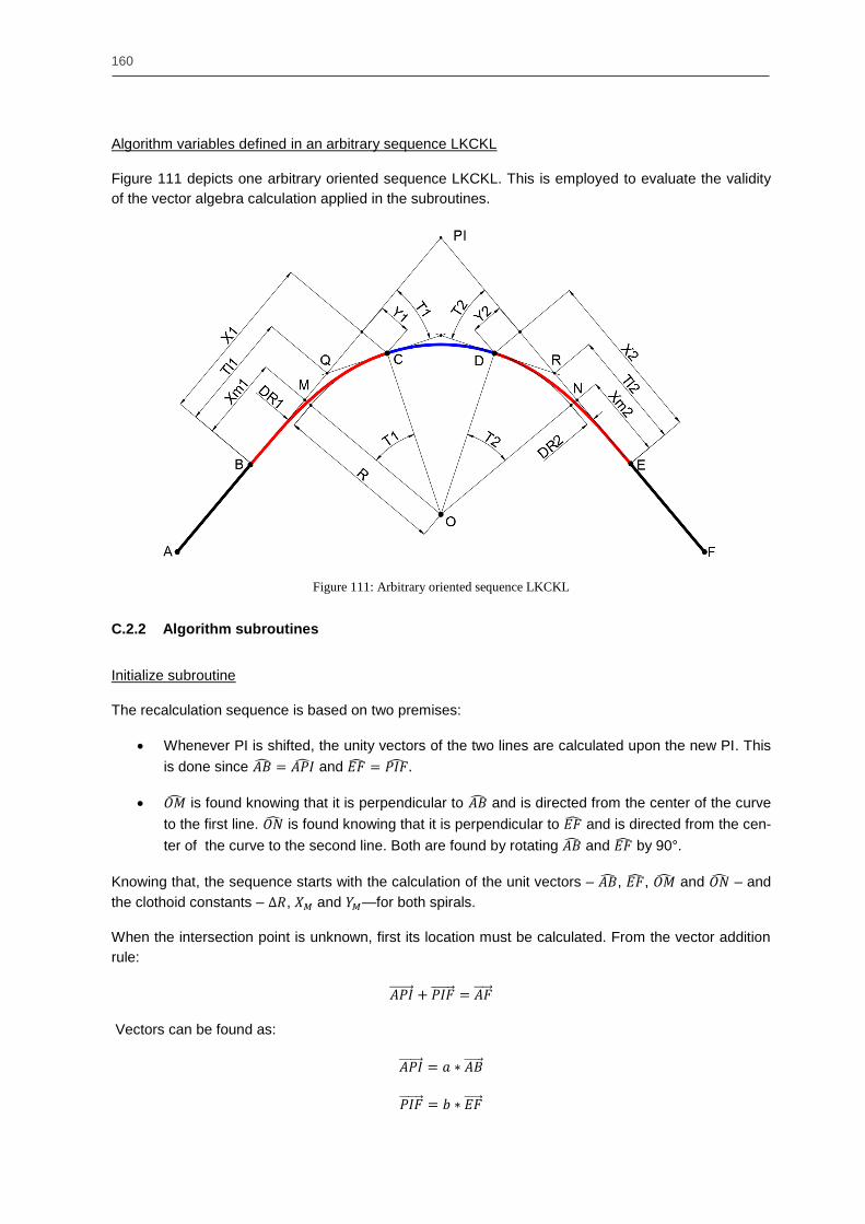
160
Algorithm variables defined in an arbitrary sequence LKCKL
Figure 111 depicts one arbitrary oriented sequence LKCKL. This is employed to evaluate the validity
of the vector algebra calculation applied in the subroutines.
Figure 111: Arbitrary oriented sequence LKCKL
C.2.2 Algorithm subroutines
Initialize subroutine
The recalculation sequence is based on two premises:
Whenever PI is shifted, the unity vectors of the two lines are calculated upon the new PI. This
is done since and
is found knowing that it is perpendicular to and is directed from the center of the curve
to the first line. is found knowing that it is perpendicular to and is directed from the cen-
ter of the curve to the second line. Both are found by rotating and by 90°.
Knowing that, the sequence starts with the calculation of the unit vectors – , , and – and
the clothoid constants – , and —for both spirals.
When the intersection point is unknown, first its location must be calculated. From the vector addition
rule:
Vectors can be found as:
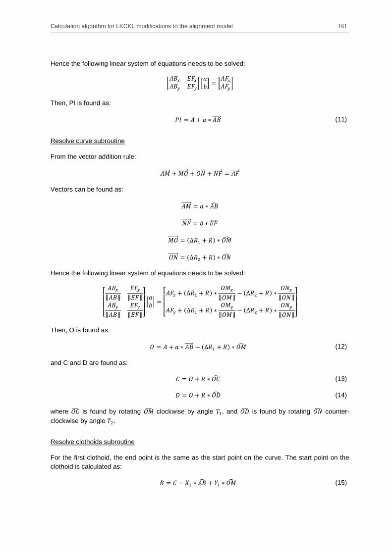
Calculation algorithm for LKCKL modifications to the alignment model 161
Hence the following linear system of equations needs to be solved:
[
] * + [
]
Then, PI is found as:
(11)
Resolve curve subroutine
From the vector addition rule:
Vectors can be found as:
Hence the following linear system of equations needs to be solved:
[
‖ ‖
‖ ‖
‖ ‖
‖ ‖]
* +
[
‖ ‖
‖ ‖
‖ ‖
‖ ‖]
Then, O is found as:
(12)
and C and D are found as:
(13)
(14)
where is found by rotating clockwise by angle , and is found by rotating counter-
clockwise by angle .
Resolve clothoids subroutine
For the first clothoid, the end point is the same as the start point on the curve. The start point on the
clothoid is calculated as:
(15)

162
and Q is found as:
(16)
Similarly, for the second clothoid, the start point is the same as the end point on the curve (following
the alignment direction). The end point on the clothoid is calculated as:
(17)
and R is found as:
(18)
Resolve lines subroutine
Based on the arbitrary sequence geometry, the end point of the first line is the same as the starting
point of the first clothoid, and the starting point of the second line is the same as the end point of the
second clothoid.
C.3. Calculation of the internal points
Once the connection points are solved, the length of the alignment segments can be calculated. Since
the number of internal points is constant for all the segments, the distance between two consecutive
points can be calculated as for the straight line and clothoid, and as a fraction of the angle
defined by the circular sector θ.
Based on the example of the line AB, the coordinates of the internal points for a line are calculated as:
(19)
(
√
√ ) (20)
The internal points of the clothoid are calculated by laying the clothoid on the abscissas‘ axis, and
rotating the coordinates as:
(21)
*
+ *
+ [
] (22)


![[DE] Elektronische Archivierung & Digital Preservation. Status, Technologien und Entwicklung](https://static.fdokument.com/doc/165x107/54b398f84a795905308b4569/de-elektronische-archivierung-digital-preservation-status-technologien-und-entwicklung.jpg)


![[DE] Elekronische Archivierung und Digital Preservation | Dr. Ulrich Kampffmeyer | VdW-Arbeitstagung | Potsdam 2009](https://static.fdokument.com/doc/165x107/58f1bd5e1a28abb14d8b45f7/de-elekronische-archivierung-und-digital-preservation-dr-ulrich-kampffmeyer.jpg)