DD Katalog Befestigungstechnik-3 - KEIL
6
UNDERCUT ANCHORS Museum of WW II, Gdańsk, PL, © Kwadrat Gdyni KEIL undercut anchors attach façade panels securely and invisibly to the substructure. Our high-quality fixing elements are available in different designs and with matching spacer discs. 17 ASSEMBLY INSTRUCTIONS UNDERCUT ANCHORS FIXING DEVICES DRILLING TOOLS DRILLING TECHNIQUE ASSEMBLY AIDS GENERAL INFORMATION INTERESTING FACTS
Transcript of DD Katalog Befestigungstechnik-3 - KEIL
UNDERCUT ANCHORS
Museum of WW II, Gdańsk, PL, © Kwadrat Gdyni
KEIL undercut anchors attach façade panels securely and invisibly to the substructure. Our high-quality fixing elements are available in different designs and with matching spacer discs.
17
ASSE
MBL
Y IN
STRU
CTIO
NSUN
DERC
UT A
NCHO
RSFI
DEV
ICES
DRIL
LING
TO
OLS
DRIL
LING
TEC
HNIQ
UEAS
SEM
BLY
AIDS
GENE
RAL
INFO
RMAT
ION
INTE
REST
ING
FACT
S
UNDERCUT ANCHOR KH AA
hmin = panel thickness[mm]
hS= insertion depth[mm]
XZ= clamping thickness[mm]
l4 = nominal length[mm]
DS = bolt head Ø[mm]
article no.
6.0 4.0 1.5 M6x8.5 14 555 020 8206.0 4.0 3.0 M6x10 14 555 020 7428.0 5.5 0.0 M6x8.5 14 555 020 8568.0 5.5 1.5 M6x10 14 555 020 7248.0 5.5 3.0 M6x11.5 14 555 020 7129.5 7.0 0.0 M6x10 14 555 020 8049.5 7.0 1.5 M6x11.5 14 555 020 7809.5 7.0 3.0 M6x13 14 555 020 830
11.0 8.5 0.0 M6x11.5 14 555 020 82311.0 8.5 1.5 M6x13 14 555 020 75211.0 8.5 3.0 M6x14.5 14 555 020 77713.0 10.0 0.0 M6x13 14 555 020 80913.0 10.0 1.5 M6x14.5 14 555 020 73413.0 10.0 3.0 M6x16 14 555 020 71513.0 10.0 6.0 M6x19 14 555 020 84814.5 11.5 0.0 M6x14.5 14 555 020 70016.0 13.0 1.5 M6x17.5 14 555 020 80218.0 15 0.0 M6x17.5 14 555 020 81518.0 15 1.5 M6x19 14 555 020 75618.0 15 3.0 M6x20.5 14 555 020 75918.0 15 6.0 M6x23.5 14 555 020 826
Further dimensions on request.
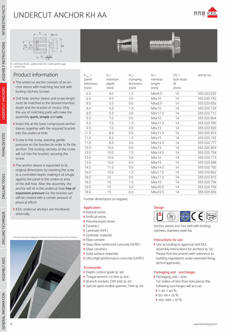
Product information The undercut anchor consists of an an-chor sleeve with matching hex bolt with locking ratchets (screw).
Drill hole, anchor sleeve and screw length must be matched to the desired insertion depth and the bracket of choice. Only the use of matching parts will make the assembly quick, simple and safe.
Insert the at the base compressed anchor sleeve, together with the required bracket, into the undercut hole.
Screw in the screw, exerting gentle pressure on the bracket (in order to fix the anchor). The locking ratchets of the screw will cut into the bracket, securing the screw.
The anchor sleeve is expanded to its original dimensions by inserting the scew to a controlled depth, making it sit snugly against the panel in the undercut area of the drill hole. After the assembly, the anchor will sit in the undercut hole free of expansion pressure (i.e. the bracket can still be rotated with a certain amount of physical effort).
KEIL undercut anchors are monitored externally.
ETA
Application Natural stone Artificial stone Manufactured stone Ceramics Laminate (HPL) Synthetic material Fibre cement Glass fibre reinforced concrete (GFRC) Glass ceramics Solid surface materials Ultra high performance concrete (UHPC)
Accessories Depth control guide (p. 56) Torque wrench 1–6 Nm (p. 60) Wrench sockets, DIN 3126 (p. 61) Special open-ended spanner, SW9 (p. 61)
Design
Anchor sleeve incl. hex bolt with locking ratchets, stainless steel A4.
Instructions for use Use according to approval and KEIL assembly instructions for anchors (p. 12). Please find documents with relevance to building regulations under www.keil-fixing.de/en/approvals.
Packaging unit - surcharges Packaging unit = 500.For orders of less than 500 pieces the following surcharges will accrue: 1–49 + 40 % 50–99 + 25 % 100–499 + 10 %
INTE
REST
ING
FACT
SAS
SEM
BLY
INST
RUCT
IONS
UNDE
RCUT
ANC
HORS
FIXI
NG D
EVIC
ESDR
ILLI
NG T
OO
LSDR
ILLI
NG T
ECHN
IQUE
ASSE
MBL
Y AI
DSGE
NERA
L IN
FORM
ATIO
N
D2= 9
D1= 7
SW = 9
DS
hS
h
XA XZ
= 3
Microsoft Germany Headquarters, Munich, DE © Andreas Frisch, GSP Architekten
18
D1 = drill hole Ø; D2 = undercut Ø; SW = shaft spanner gap XA = anchor hex
www.keil-fixing.de/en
UNDERCUT ANCHOR KH AA 9/12
hmin = panel thickness[mm]
hS = insertion depth[mm]
Xz = clamping thickness[mm]
thread length
[mm]
DS =bolt head Ø[mm]
article no.
25.0 20.0 0.0 M6x23 14 555 020 60125.0 20.0 1.5 M6x24.5 14 555 020 60225.0 20.0 3.0 M6x26 14 555 020 60325.0 20.0 6.0 M6x29 14 555 020 604
Further dimensions on request.
ApplicationFor the invisible, back-mounted attachment of façade panels, especially of soft stones.
Accessories Depth control guide (p. 56) Torque wrench, 1–6 Nm (p. 60)
Design
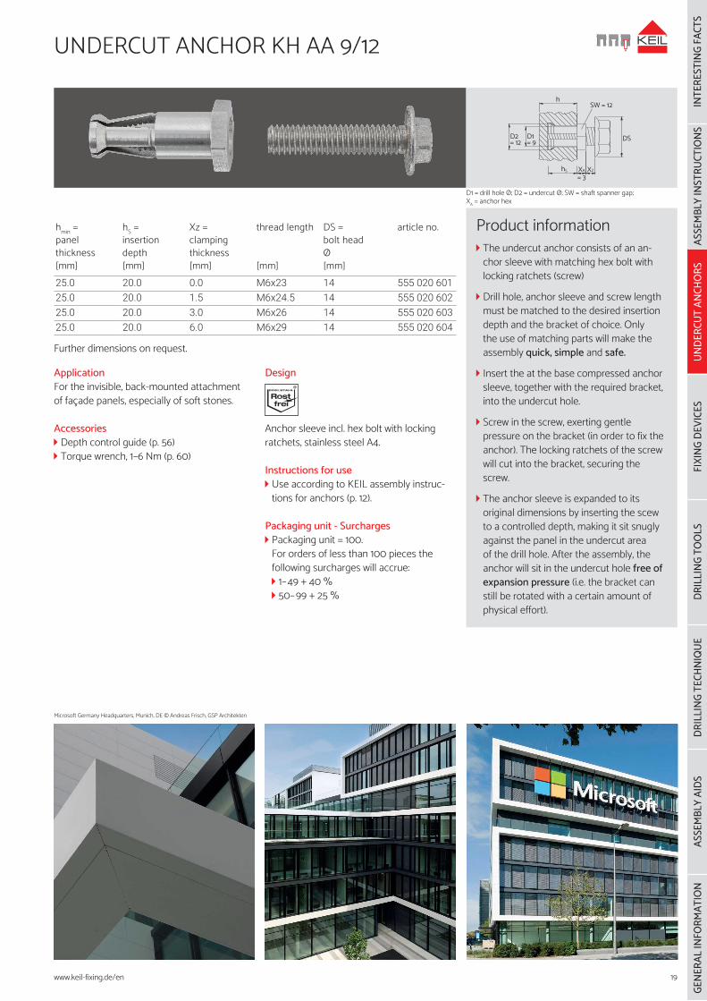
Anchor sleeve incl. hex bolt with locking ratchets, stainless steel A4.
Instructions for use Use according to KEIL assembly instruc-tions for anchors (p. 12).
Packaging unit - Surcharges Packaging unit = 100.For orders of less than 100 pieces the following surcharges will accrue: 1–49 + 40 % 50–99 + 25 %
hSW = 12
DSD2= 12
D1= 9
hS XA XZ
= 3
Product information The undercut anchor consists of an an-chor sleeve with matching hex bolt with locking ratchets (screw)
Drill hole, anchor sleeve and screw length must be matched to the desired insertion depth and the bracket of choice. Only the use of matching parts will make the assembly quick, simple and safe.
Insert the at the base compressed anchor sleeve, together with the required bracket, into the undercut hole.
Screw in the screw, exerting gentle pressure on the bracket (in order to fix the anchor). The locking ratchets of the screw will cut into the bracket, securing the screw.
The anchor sleeve is expanded to its original dimensions by inserting the scew to a controlled depth, making it sit snugly against the panel in the undercut area of the drill hole. After the assembly, the anchor will sit in the undercut hole free of expansion pressure (i.e. the bracket can still be rotated with a certain amount of physical effort).
Microsoft Germany Headquarters, Munich, DE © Andreas Frisch, GSP Architekten
19
D1 = drill hole Ø; D2 = undercut Ø; SW = shaft spanner gap; XA = anchor hex
ASSE
MBL
Y IN
STRU
CTIO
NSUN
DERC
UT A
NCHO
RSFI
DEV
ICES
DRIL
LING
TO
OLS
DRIL
LING
TEC
HNIQ
UEAS
SEM
BLY
AIDS
GENE
RAL
INFO
RMAT
ION
INTE
REST
ING
FACT
S
www.keil-fixing.de/en
20
SPACER DISC KH
outerØ
[mm]
height up tohex [mm]
heightincl.hex [mm]
SWA = spanner gap without[mm]
SWB = spanner gap within[mm]
article no.
15 6 7.5 SW9 SW9 555 432 20018 6 7.5 SW9 SW12 555 432 201
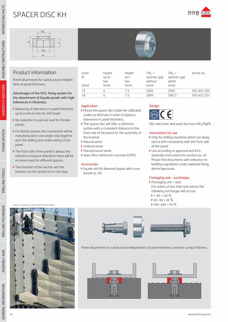
Application Mount the spacer disc inside the calibrated undercut drill hole in order to balance tolerances in panel thickness.
The spacer disc will offer a reference surface with a consistent distance to the front side of the panel for the assembly of the bracket.
Natural stone Artificial stone Manufactured stone Glass fibre reinforced concrete (GFRC)
Accessories façade drill bit diamond tipped with coun-tersink (p. 29)
Design
Disc with inner and outer hex from AlCuMgPb
Instructions for use Only for drilling machines which are desig-ned to drill consistantly with the front side of the panel.
Use according to approval and KEIL assembly instructions for anchors (p. 12). Please find documents with relevance to building regulations under www.keil-fixing.de/en/approvals.
Packaging unit - surcharges Packaging unit = 500.For orders of less than 500 pieces the following surcharges will accrue: 1–49 + 40 % 50–99 + 25 % 100–499 + 10 %
ETA
Product informationPanel attachment for substructure indepen-dent of panel thickness.
Advantages of the KEIL fixing system for the attachment of façade panels with high tolerances in thickness:
Balancing of tolerances in panel thickness up to 6 mm (4 mm for drill head).
No reduction in pull-out load for thinner panels.
For thicker panels, the countersink will be manufactured in one single step together wich the drilling and undercutting of the panel.
The front side of the panel is always the reference measure (therefore there will be no more need for different spacers.
The insertion of the anchor and the bracket can be carried out in one step.
SWA
67,5
SWB
Ø
Panel attachment to substructure independent of panel thickness and rear surface flatness.
Museum of Liverpool, Liverpool, GB © Vincent Phillips
INTE
REST
ING
FACT
SAS
SEM
BLY
INST
RUCT
IONS
UNDE
RCUT
ANC
HORS
FIXI
NG D
EVIC
ESDR
ILLI
NG T
OO
LSDR
ILLI
NG T
ECHN
IQUE
ASSE
MBL
Y AI
DSGE
NERA
L IN
FORM
ATIO
N
www.keil-fixing.de/en
UNDERCUT ANCHOR KH BH
21
ETA
Application Natural stone Artificial stone Manufactured stone Ceramics Laminate (HPL) Synthetic material Fibre cement Glass fibre reinforced concrete (GFRC) Glass ceramics
Accessories Depth control guide (p. 56) Wrench sockets, DIN 3126 (p. 61) Special open-ended spanner, SW9 (p. 61) Screw-in tool for stud bolts (p. 61)
Design
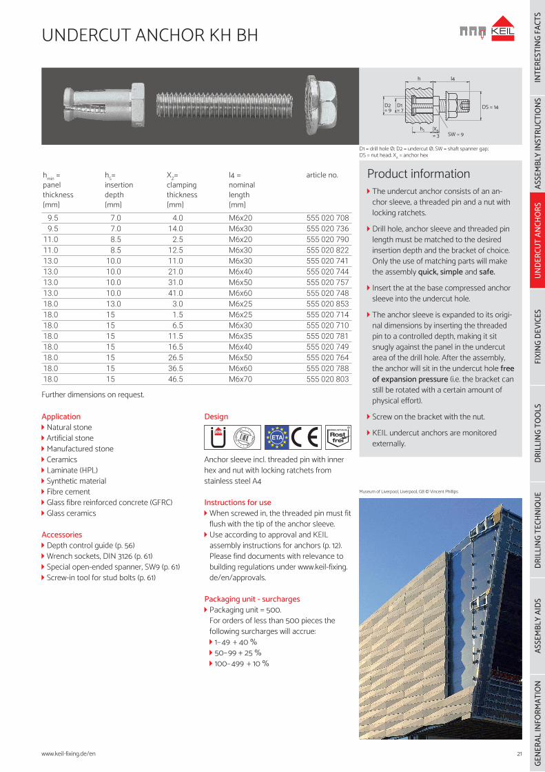
Anchor sleeve incl. threaded pin with inner hex and nut with locking ratchets from stainless steel A4
Instructions for use When screwed in, the threaded pin must fit flush with the tip of the anchor sleeve.
Use according to approval and KEIL assembly instructions for anchors (p. 12). Please find documents with relevance to building regulations under www.keil-fixing.de/en/approvals.
Packaging unit - surcharges Packaging unit = 500.For orders of less than 500 pieces the following surcharges will accrue: 1–49 + 40 % 50–99 + 25 % 100–499 + 10 %
Product information The undercut anchor consists of an an-chor sleeve, a threaded pin and a nut with locking ratchets.
Drill hole, anchor sleeve and threaded pin length must be matched to the desired insertion depth and the bracket of choice. Only the use of matching parts will make the assembly quick, simple and safe.
Insert the at the base compressed anchor sleeve into the undercut hole.
The anchor sleeve is expanded to its origi-nal dimensions by inserting the threaded pin to a controlled depth, making it sit snugly against the panel in the undercut area of the drill hole. After the assembly, the anchor will sit in the undercut hole free of expansion pressure (i.e. the bracket can still be rotated with a certain amount of physical effort).
Screw on the bracket with the nut.
KEIL undercut anchors are monitored externally.
h l4
XAhS
= 3 SW = 9
DS = 14D2= 9
D1= 7
hmin = panel thickness[mm]
hS= insertion depth[mm]
XZ= clamping thickness[mm]
l4 = nominal length[mm]
article no.
9.5 7.0 4.0 M6x20 555 020 7089.5 7.0 14.0 M6x30 555 020 736
11.0 8.5 2.5 M6x20 555 020 79011.0 8.5 12.5 M6x30 555 020 82213.0 10.0 11.0 M6x30 555 020 74113.0 10.0 21.0 M6x40 555 020 74413.0 10.0 31.0 M6x50 555 020 75713.0 10.0 41.0 M6x60 555 020 74818.0 13.0 3.0 M6x25 555 020 85318.0 15 1.5 M6x25 555 020 71418.0 15 6.5 M6x30 555 020 71018.0 15 11.5 M6x35 555 020 78118.0 15 16.5 M6x40 555 020 74918.0 15 26.5 M6x50 555 020 76418.0 15 36.5 M6x60 555 020 78818.0 15 46.5 M6x70 555 020 803
Further dimensions on request.
D1 = drill hole Ø; D2 = undercut Ø; SW = shaft spanner gap; DS = nut head; XA = anchor hex
Museum of Liverpool, Liverpool, GB © Vincent Phillips
ASSE
MBL
Y IN
STRU
CTIO
NSUN
DERC
UT A
NCHO
RSFI
DEV
ICES
DRIL
LING
TO
OLS
DRIL
LING
TEC
HNIQ
UEAS
SEM
BLY
AIDS
GENE
RAL
INFO
RMAT
ION
INTE
REST
ING
FACT
S
www.keil-fixing.de/en
22
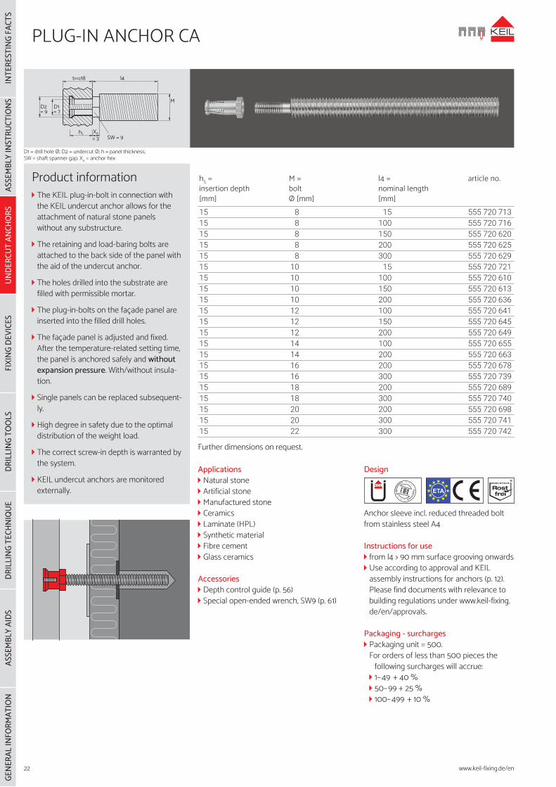
PLUG-IN ANCHOR CA
hS = insertion depth[mm]
M = bolt Ø [mm]
l4 = nominal length[mm]
article no.
15 8 15 555 720 71315 8 100 555 720 71615 8 150 555 720 62015 8 200 555 720 62515 8 300 555 720 62915 10 15 555 720 72115 10 100 555 720 61015 10 150 555 720 61315 10 200 555 720 63615 12 100 555 720 64115 12 150 555 720 64515 12 200 555 720 64915 14 100 555 720 65515 14 200 555 720 66315 16 200 555 720 67815 16 300 555 720 73915 18 200 555 720 68915 18 300 555 720 74015 20 200 555 720 69815 20 300 555 720 74115 22 300 555 720 742
Further dimensions on request.
ETA
Applications Natural stone Artificial stone Manufactured stone Ceramics Laminate (HPL) Synthetic material Fibre cement Glass ceramics
Accessories Depth control guide (p. 56) Special open-ended wrench, SW9 (p. 61)
Design
Anchor sleeve incl. reduced threaded bolt from stainless steel A4
Instructions for use from l4 > 90 mm surface grooving onwards Use according to approval and KEIL assembly instructions for anchors (p. 12). Please find documents with relevance to building regulations under www.keil-fixing.de/en/approvals.
Packaging - surcharges Packaging unit = 500.For orders of less than 500 pieces the
following surcharges will accrue: 1–49 + 40 % 50–99 + 25 % 100–499 + 10 %
Product information The KEIL plug-in-bolt in connection with the KEIL undercut anchor allows for the attachment of natural stone panels without any substructure.
The retaining and load-baring bolts are attached to the back side of the panel with the aid of the undercut anchor.
The holes drilled into the substrate are filled with permissible mortar.
The plug-in-bolts on the façade panel are inserted into the filled drill holes.
The façade panel is adjusted and fixed. After the temperature-related setting time, the panel is anchored safely and without expansion pressure. With/without insula-tion.
Single panels can be replaced subsequent-ly.
High degree in safety due to the optimal distribution of the weight load.
The correct screw-in depth is warranted by the system.
KEIL undercut anchors are monitored externally.
l4
M
CASW = 9
t>=≥18
D1= 7
D2= 9
hS XA
= 3
D1 = drill hole Ø; D2 = undercut Ø; h = panel thickness; SW = shaft spanner gap; XA = anchor hex
INTE
REST
ING
FACT
SAS
SEM
BLY
INST
RUCT
IONS
UNDE
RCUT
ANC
HORS
FIXI
NG D
EVIC
ESDR
ILLI
NG T
OO
LSDR
ILLI
NG T
ECHN
IQUE
ASSE
MBL
Y AI
DSGE
NERA
L IN
FORM
ATIO
N
www.keil-fixing.de/en