Der Einbau der schotterlosen Fahrbahn im Gotthard...
12
SWISS TUNNEL CONGRESS 2012 2 Gotthard-Basistunnel • Einbau der schotterlosen Fahrbahn 2 Der Einbau der schotterlosen Fahrbahn im Gotthard-Basistunnel Eine Produktion wie am laufenden Band Die im GBT-Jahrhundertprojekt sehr strengen werkvertraglichen Anforderungen an die schotterlose Fahrbahn sowie die besonderen logistischen Randbedingungen stellen für die Ausführenden eine grosse Herausforderung dar. Nur mit einem standardisierten, hoch mechanisierten Fertigungsprozess, vergleichbar mit einer industriellen Fliessbandproduktion, lässt sich das Werk unter Berücksichtigung der geforderten Qualität und der notwendigen Arbeitssicherheit herstellen. Laying the Ballastless Track in the Gotthard Base Tunnel Forging ahead with production The extremely strict contractual demands on the ballastless track for the GBT scheme of the century as well as the special logistical general conditions represent a major challenge for those responsible for its execution. It is only possible to complete the project given the required quality and the necessary indus- trial safety with a standardised, highly mechanised production process, comparable with an industrial assembly belt procedure. 1 Starting Position The Transtec Gotthard JV was commissioned by the AlpTransit Gotthard AG, the client for the Gotthard NEAT (New Railway Link through the Alps = NRLA) axis, with the planning, installation and operation of the rail infrastruc- ture in the Gotthard Base Tunnel (GBT). In contrast to the production of the raw construction the client awarded the contractor a general contractor’s assignment. The global contractual sum amounts to around 1.7 billion CHF and embraces the furnishing of the entire tunnel with the rail infrastructure, which is divided into the following sub-sec- tions: laying the track, installing the 50 Hz power supply, the cable equipment, the 16.7 Hz traction power supply, the telecommunications for landline and radio as well as the signalling and safety equipment. To fulfil this task, com- panies leading in their respective fields within the Transtec Gotthard JV – Alpiq, Alcatel-Lucent/Thales, Alpine Bau and Balfour Beatty Rail – came together to form an ordinary partnership in accordance with Art. 530 FF OR (Swiss Law) in order to jointly master the opportunities and risks of this project of the century as equal partners, each with 25 % participation (Fig. 1). 1 Ausgangslage Die Arbeitsgemeinschaft Transtec Gotthard wurde von der AlpTransit Gotthard AG, Bauherr der NEAT Achse Gotthard, mit der Planung, dem Einbau und der Inbetriebnahme der Bahntechnik im Gotthard-Basistunnel (GBT) beauftragt. Im Unterschied zur Herstellung des Rohbaus übertrug der Bau- herr dem Auftragnehmer eine Generalunternehmeraufgabe. Die globale Vertragssumme beträgt ca. 1.7 Mrd. CHF und umfasst die Gesamtausstattung des Tunnels mit der Bahn- technik, die sich in folgende Teilgewerke aufteilt: Erstellung Detlef Obieray, Dipl. Ing. (univ.), Balfour Beatty Rail Schweiz GmbH, Stans/CH 1 Der Generalunternehmer Bahntechnik Gotthard The general contractor Rail Technology Gotthard (Quelle/Source: TTG)
Transcript of Der Einbau der schotterlosen Fahrbahn im Gotthard...

SWISS TUNNEL CONGRESS 20122
Gotthard-Basistunnel • Einbau der schotterlosen Fahrbahn
2
Der Einbau der schotterlosen Fahrbahn im Gotthard-BasistunnelEine Produktion wie am laufenden BandDie im GBT-Jahrhundertprojekt sehr strengen werkvertraglichen Anforderungen an die schotterlose Fahrbahn sowie die besonderen logistischen Randbedingungen stellen für die Ausführenden eine grosse Herausforderung dar. Nur mit einem standardisierten, hoch mechanisierten Fertigungsprozess, vergleichbar mit einer industriellen Fliessbandproduktion, lässt sich das Werk unter Berücksichtigung der geforderten Qualität und der notwendigen Arbeitssicherheit herstellen.
Laying the Ballastless Track in the Gotthard Base TunnelForging ahead with productionThe extremely strict contractual demands on the ballastless track for the GBT scheme of the century as well as the special logistical general conditions represent a major challenge for those responsible for its execution. It is only possible to complete the project given the required quality and the necessary indus-trial safety with a standardised, highly mechanised production process, comparable with an industrial assembly belt procedure.
1 Starting Position
The Transtec Gotthard JV was commissioned by the AlpTransit Gotthard AG, the client for the Gotthard NEAT (New Railway Link through the Alps = NRLA) axis, with the planning, installation and operation of the rail infrastruc-ture in the Gotthard Base Tunnel (GBT). In contrast to the production of the raw construction the client awarded the contractor a general contractor’s assignment. The global contractual sum amounts to around 1.7 billion CHF and embraces the furnishing of the entire tunnel with the rail infrastructure, which is divided into the following sub-sec-tions: laying the track, installing the 50 Hz power supply, the cable equipment, the 16.7 Hz traction power supply, the telecommunications for landline and radio as well as the signalling and safety equipment. To fulfil this task, com-panies leading in their respective fields within the Transtec Gotthard JV – Alpiq, Alcatel-Lucent/Thales, Alpine Bau and Balfour Beatty Rail – came together to form an ordinary partnership in accordance with Art. 530 FF OR (Swiss Law) in order to jointly master the opportunities and risks of this project of the century as equal partners, each with 25 % participation (Fig. 1).
1 Ausgangslage
Die Arbeitsgemeinschaft Transtec Gotthard wurde von der AlpTransit Gotthard AG, Bauherr der NEAT Achse Gotthard, mit der Planung, dem Einbau und der Inbetriebnahme der Bahntechnik im Gotthard-Basistunnel (GBT) beauftragt. Im Unterschied zur Herstellung des Rohbaus übertrug der Bau-herr dem Auftragnehmer eine Generalunternehmeraufgabe. Die globale Vertragssumme beträgt ca. 1.7 Mrd. CHF und umfasst die Gesamtausstattung des Tunnels mit der Bahn-technik, die sich in folgende Teilgewerke aufteilt: Erstellung
Detlef Obieray, Dipl. Ing. (univ.), Balfour Beatty Rail Schweiz GmbH, Stans/CH
1 Der Generalunternehmer Bahntechnik Gotthard The general contractor Rail Technology Gotthard (Quelle/Source: TTG)

SWISS TUNNEL CONGRESS 2012 3
Gotthard Base Tunnel • Installation of the Ballastless Track
3
L’installation de la voie sans ballast dans le tunnel de base du Saint-GothardUne production comme à la chaîne
Dans le projet historique du tunnel du Saint-Gothard, les exigences très strictes posées à la voie sans ballast par le cahier des charges, ainsi que les conditions logistiques périphériques particulières constituent un grand défi pour les exécutants. Seul un processus de production standar-disé, hautement mécanisé, comparable à une production industrielle à la chaîne, peut permettre de réaliser cet ouvrage dans la qualité exigée et avec la sécurité de travail nécessaire.
Costruzione del binario senza massicciata nella galleria di base del GottardoUn lavoro analogo alla catena di montaggio
I severissimi requisiti in termini di contratto d’opera per il binario senza massicciata, nonché le condizioni logistiche particolari nel progetto secolare del GBT, rappresentano una grande sfida per le parti che lo eseguono. Soltanto con una procedura di produzione standardizzata e altamente meccanizzata, paragonabile a una catena di montaggio industriale, è possibile realizzare l’opera tenendo conto della qualità e della sicurezza sul lavoro richiesti.
der Fahrbahn, Einbau der Stromversorgung mit 50 Hz, der Kabelanlagen, der Fahrstromversorgung mit 16.7 Hz, der Telekommunikation für Festnetz und Funk sowie die Signali-sierungs- und Sicherungsanlagen. Zur Erfüllung der Aufgabe sind die in ihren Fachbereichen führenden Unternehmen der Arge Transtec Gotthard – die Firmen Alpiq, Alcatel-Lucent/Thales, Alpine Bau und Balfour Beatty Rail – in einer ein-fachen Gesellschaft i. S. von Art. 530 ff. OR zusammenge-schlossen, um als gleichberechtigte Partner mit jeweils 25 % Beteiligung Chancen und Risiken dieses Jahrhundertprojek-tes gemeinsam zu teilen (Bild 1).
Die Transtec Gotthard führt, koordiniert und integriert als Projektgesellschaft die heterogenen Fachkompetenzen der Teilgewerke, die zur Realisierung des Gesamtauftrages not-wendig sind und erbringt dabei übergeordnete Leistungen wie die Gesamtprojektleitung, Logistik und temporäre Instal-lationen. Die einzelnen Gewerke werden im Innenverhältnis als Subunternehmerleistungen auf der Grundlage von Werk-verträgen ausgeführt.
Der folgende Beitrag konzentriert sich ausschliesslich auf das Teilgewerk Fahrbahn und wird die besonderen Anfor-derungen an die Planung und Realisierung der Fahrbahn in diesem Projekt beleuchten. Umfassendere Informationen zur Gesamtprojektorganisation wurden bereits beim Swiss Tunnel Congress 2010 vorgestellt.
2 Die Arge Fahrbahn Transtec Gotthard
Die Arge Fahrbahn Transtec Gotthard ist im Zuge eines soge-nannten Back-to-back-Vertrages für die Umsetzung des Teil-gewerkes Fahrbahn verantwortlich. Wie die Dach-Arge Trans-tec Gotthard ist auch sie eine einfache Gesellschaft nach Art. 530 ff. OR und wird gleichberechtigt zu je 50 % von den beiden Firmen Balfour Beatty Rail und Alpine Bau gebildet (Bild 2).
The Transtec Gotthard, as project company, manages, co-ordinates and integrates the heterogeneous specialised competences of the sub-contractors, which are required to accomplish the total contract and in this connection fulfils superordinated tasks such as overall project management, logistics and temporary installations. The individual services are executed as sub-contractor performances on the basis of works contracts.
The following report concentrates solely on the sub-section track and will explain the special demands posed in plan-ning and accomplishing the track for this scheme. More comprehensive details relating to the overall project or-ganisation were already presented at the 2010 Swiss Tunnel Congress.
2 The Transtec Gotthard Track JV
The Transtec Gotthard Track JV is responsible for laying the track within the context of what is known as a back-to-back contract. Just like the umbrella Transtec Gotthard JV, it is also an ordinary partnership in accordance with Art. 530 ff OR and is owned equally by the 2 firms Balfour Beatty Rail and Alpine Bau (Fig. 2).
2 Der Subunternehmer für den Einbau der schotterlosen Fahrbahn im GBT The sub-contractor for installing the ballastless track in the GBT (Quelle/Source: TTG)
SWISS TUNNEL CONGRESS 20124
Gotthard-Basistunnel • Einbau der schotterlosen Fahrbahn
Der Auftrag zur Herstellung des Fahrweges umfasst die Pla-nung, Lieferung, Herstellung und Inbetriebsetzung folgen-der Fahrbahnkomponenten:• 115 km schotterlose Fahrbahn im GBT (inkl. Übergänge
Multifunktionsstellen) in den beiden jeweils 57 km langen Tunnelröhren
• 2 Stück 12 000er „perspektivische“ Weichen für eine mögliche Erweiterung des GBT im Nordabschnitt zur Umfah-rung von Altdorf; es werden die Schwellensätze für je eine Weiche bereits als schotterlose Fahrbahn eingebaut
• 8 Stück 1600er Weichen mit beweglichem Herzstück als schotterlose Fahrbahn in den beiden Multifunktionsstellen
• 4 Übergangskonstruktionen schotterlose Fahrbahn – Schotterfahrbahn in den Tunnelportalzonen
• 31 km Schotterfahrbahn für den Stammlinienanschluss• 22 Stück 1600er Klothoidenweichen in der Schotterfahr-
bahn, davon 15 mit beweglichem Herzstück
Für die Herstellung der schotterlosen Fahrbahn im Tunnel werden insgesamt 131 000 m3 Beton, 380 000 LVTSchwellen-blöcke (Low-Vibration-Track) und 230 km Schienen benötigt.
3 Anforderungen an die schotterlose Fahrbahn
Der Anforderungskatalog an die schotterlose Fahrbahn im GBT ist äusserst streng und gegenüber vergleichbaren Pro-jekten in Deutschland oder z. B. dem Lötschbergtunnel noch-mals deutlich verschärft worden. Die Herausforderungen an den Gleisbau bewegen sich in Toleranzmassen, die beinahe mit einem Schweizer Uhrwerk verglichen werden können. Als zulässige Abweichung vom Sollwert bezogen auf eine glei-tende Streckenbasis von 5000 m, bei Messpunktabständen von 0.5 m, ist z. B. für die Spurweite eine Mittelwertabwei-chung von -0.5 bis +1.5 mm mit einer Standardabweichung vom Mittelwert von ≤ 0.5 mm vorgegeben. Die zulässige Abweichung der absoluten Lage und Höhe vom Mittelwert ist mit ± 0.5 mm mit einer erlaubten Standardabweichung vom Mittelwert von 1.0 mm gefordert. Noch strenger sind die Toleranzvorgaben für die Überhöhung der schotterlosen Fahrbahn, hier liegt die erlaubte Mindestwertabweichung bei ± 0.3 mm mit einer Standardabweichung vom Mittelwert von 0.3 mm. Für die innere Genauigkeit des Gleises muss der Un-terschied zweier benachbarter Pfeilhöhen, gemessen in Ab-ständen von 5 m in der Mitte der Sehne, < 2 mm sein. Insge-samt darf die Fahrbahn eine Verwindung von Nmax = 0.05 % (Messbasis 1 m) nicht überschreiten. Die Schienenneigung des mit UIC 60 E1 Schienen hergestellten Gleisrostes muss in den Toleranzgrenzen von 1:45 bis 1:35 liegen. Mit einer ge-planten Gleissteifigkeit von CG = 80.6 kN/mm muss sich die gemessene vertikale Einfederung des Gleises, bei einer Achs-last von 200 kN und einer Testgeschwindigkeit ≤ 15 km/h, im Toleranzbereich von 1 bis 1.5 mm bewegen (Bild 3).
Ähnlich stringent verhält es sich mit den projektspezifischen Anforderungen an den Betonbau. Der Vergussbeton für die schotterlose Fahrbahn muss folgende Mindestanforderun-gen erfüllen:
The contract for producing the track comprises the planning, supply, production and setting into operation of the follow-ing track components:• 115 km of ballastless track in the GBT (including the MFS
crossovers) in the 2 each 57 km long tunnel bores• two 12,000 “perspective” points for a possible extension of
the GBT in the northern section to bypass Altdorf; the sets of sleepers for points in each case have already been laid as ballastless track
• eight 1600 points with a moveable core as ballastless track in the 2 multi-function stations
• 4 crossover structures as ballastless track – ballast track in the tunnel portal zones
• 31 km of ballast track for the mainline connection• twenty two 1600 klothoid points in the ballast track, 15 of
which are with a moveable core
Altogether 131,000 m³ of concrete, 380,000 LVT sleeper blocks and 230 km of rails are needed for producing the bal-lastless track in the tunnel.
3 Demands on the ballastless track
The catalogue of requirements for the ballastless track in the GBT is extremely strict and has also been stepped up a notch
3 Fertiggestellte schotterlose Fahrbahn in Tunnelabschnitt Faido – Bodio West Completed ballastless track in the Faido – Bodio West tunnel section (Foto/Photo: TTG)

SWISS TUNNEL CONGRESS 2012 5
Gotthard Base Tunnel • Installation of the Ballastless Track
• Mindestdruckfestigkeit ≥ C25/30• Biegezugfestigkeit fcbz,m ≥ 5.5 N/mm2
• Expositionsklassen: XC3, XF3, XD3 (gem. CHNorm)• Nennwertgrösse Grösstkorn 16 mm• Klasse Chloridgehalt Cl 0.20• Nachbehandlung nach SN 505 262• Kerbfugen zur gesteuerten Rissbildung im Abstand von 4.20 m
• Zement und Baustahl nach SN 505 262 bzw. 505 262/1
Hinsichtlich der vorgegebenen Betonsorte C25/30 für die Expositionsklassen XC3/XD3 ergeben sich folgende Randbedingungen aus den Schweizer Normen für die Beton-rezeptur:• max. W/Zequ = 0.45 (Toleranz +0.02)• min. Zequ = 344 kg/m
3
• wirksamer Wassergehalt von 168 l/m3 bei einer ermittelten Wasseraufnahme der Gesteinskörnung von 13.2 l/m3
Für den Bauunternehmer spielen aber neben den rein be-tontechnologischen Anforderungen auch die besonderen logistischen Bedingungen des GBT für den Einbau der schot-terlosen Fahrbahn eine ausschlaggebende Rolle (Bild 4). Der Vergussbeton muss eine gute Verarbeitbarkeit (Konsistenz bzw. Ausbreitmass) zur Erreichung der vertraglich geschul-deten Einbaugeschwindigkeit besitzen. Dies vor allem unter Berücksichtigung der relativ grossen Vergusshöhe unter dem Schwellenschuh von 18 cm, bei Vermeidung von Ent-mischungen der Zuschlagstoffe beim fliessenden Einbau mit hoher Einbauleistung. Dabei ist ganz besonders darauf
or 2 in comparison with comparable schemes in Germany or, say, the Lötschberg Base Tunnel. The demands on track con-struction are in fact almost comparable with what is required of a Swiss chronometer. Relating to the permissible deviation from the target value over a 5000 m sliding route basis, given measurement point gaps of 0.5 m, an average value deviation of –0.5 to 1.5 mm with a tolerated standard deviation from the average value of ≤ 0.5 mm is prescribed. The permissible deviation of the absolute position and height from the aver-age value of ± 0.5 mm with a permitted standard deviation from the average value of 1.00 mm is called for. The tolerance specifications for the banking of the ballastless track are even stricter. Here the permitted minimum deviation amounts to ± 0.3 with a standard deviation from the average value of 0.3 mm. For the internal accuracy of the track the difference between 2 neighbouring cambers, measured at 5 m gaps in the middle of the axis, has to be > 2 mm. Altogether the track must not exceed a distortion of Nmax = 0.05 % (measure-ment basis 1 m). The rail cant of the track grid produced by UIC 60 E1 rails must lie within the tolerances limits of 1:45 to 1:35. With a planned track rigidity of CG = 80.6 kN/mm, the measured vertical deflexion of the track, given an axle load of 200 kN and a test speed of > 15 km/h, must lie within a toler-ance range of 1 to 1.5 mm (Fig. 3).
The project-specific demands posed on concrete construc-tion are similarly stringent. The cast concrete for the ballast-less track must fulfil the following minimum requirements:• minimum compressive strength > C25/30• bending strength fcbz,m < 5.5 N/mm²
4 Tunnelquerschnitt mit schotterloser Fahrbahn Tunnel cross-section with ballastless track (Quelle/Source: TTG)
SWISS TUNNEL CONGRESS 20126
Gotthard-Basistunnel • Einbau der schotterlosen Fahrbahn
zu achten, dass der Unterguss des Betons unter die Schwel-lensohle des aus synthetischem Kautschuk bestehenden Gummi schuhs (SBR) möglichst blasenfrei erfolgt, um eine gute Auflagefläche des Schwellenblocks im Beton zu ge-währleisten.
Aufgrund der Komplexität der Anforderungen an die Beton-technologie und des hohen Qualitätsstandards für die Lang-lebigkeit des Gesamtsystems der schotterlosen Fahrbahn wurde von der Arge Fahrbahn ein eigenes betontechnologi-sches Projekt implementiert, welches die komplette Entwick-lung des Fahrbahnbetons abbildet und begleitet. Unterstützt wird dieses Projekt durch das akkreditierte Betonlabor Ver-suchsStollen Hagerbach (VSH); es umfasst alle Phasen der Projektentwicklung vom Engineering und Design der Beton-rezeptur über die Auswahl der Zuschlagstoffe, des Zements etc. bis hin zu unzähligen Versuchsreihen zur Verarbeitbarkeit des Betons unter den projektspezifischen Gegebenheiten. Dabei wurde sowohl die Entwicklung des Vergussbetons un-terstützt, begutachtet und begleitet, als auch im Einbaupro-zess selbst die Zusammenarbeit mit der Qualitätskontrolle und der vertraglich geforderten kontinuier lichen Nachweis-führung der eingebauten Betonqualität. Die Etablierung eines dauerhaften projektbegleitenden betontechnologi-schen Projektes und die Begleitung durch ein unabhängi-ges Labor ist in dieser Form ein Novum zum Bau von Festen Fahrbahnen und unterstreicht die besondere Bedeutung und den hohen Qualitätsanspruch dieses Gleisbauprojektes im Vergleich zu anderen Feste-Fahrbahn-Projekten (Bild 5).
Für den zukünftigen Betrieb der Strecke als Europäische Eisen bahntransversale orientieren sich die werkvertrag lichen Anforderungen bereits vollumfänglich an der Europäischen Norm für Hochgeschwindigkeitseisenbahnsysteme (TSI-HGV). Die Auslegungsgeschwindigkeiten der Strecke sind für Güterzüge auf 120–160 km/h festgelegt, für Reisezüge auf 200 km/h und für den HGV auf 230–250 km/h. Weiterhin wird auch bereits die Grundlage für zukünftigen Eisenbahn-verkehr der Streckenklasse E4 gemäss UIC 700 V mit Achslasten von bis zu 250 kN geschaffen. Pro Fahrtrichtung wird
• exposure classes: XC3, XF3, XD3 (according to CH Norm)• nominal size maximum grain 16 mm• chloride content class CI 0.20• curing according to SN 505 262• kerb joints for controlled crack formation at 4.20 m gaps• cement and structural steel according to SN 505 262 and
505 262/1
Regarding the predetermined type of cement C25/30 for exposure classes XC3/XD3, the following basic conditions result from the Swiss norms for the concrete recipe:• max. W/Cequ = 0.45 (tolerance +0.02)• min. Cequ = 344 kg/m³• effective water content of 168 l/m³ given an established
water absorption of the rock granulation of 13.2 l/m³
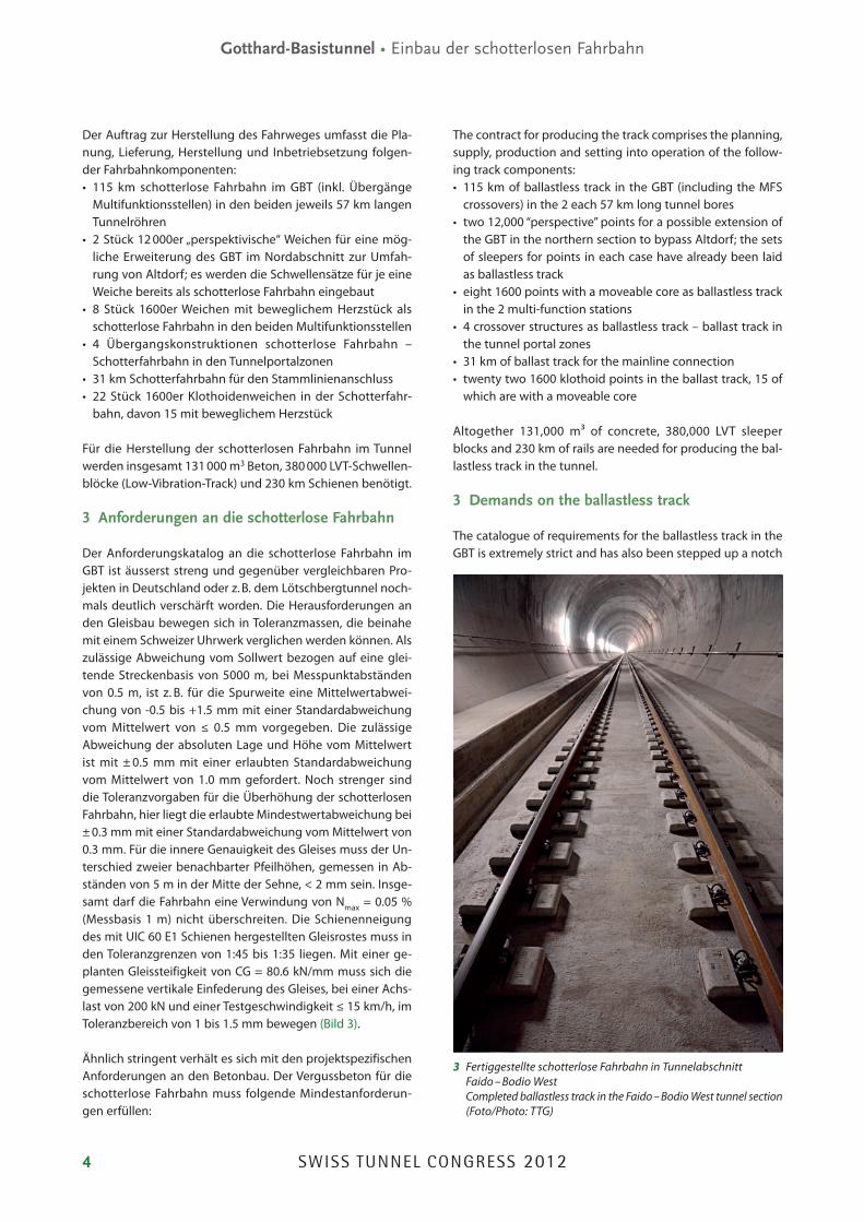
As far as the building contractor is concerned apart from the pure concrete engineering requirements the special logistical conditions of the GBT also play a decisive role for the laying of the ballastless track (Fig. 4). The cast concrete must possess good workability (consistency and slump) to attain the installation speed as laid down in the contract. This above all taking the relatively large casting height of 18 cm below the sleeper shoe, while avoiding any demixing of the aggregate materials given continuous installation at a high rate of performance. Towards this end, particular care must be taken to ensure that the concrete is cast below the sleeper shoe consisting of a shoe made of synthetic rubber (SBR) as far as possible without voids so that a good contact face for the sleeper block is created in the concrete.
On account of the complexity of the demands on the con-crete technology and the high quality standard posed on the long service life for the overall system of the ballastless track, the Track JV devised its own concrete technological project which identifies and accompanies the complete de-velopment of the track concrete. This project was supported by the accredited concrete lab VSH Hagerbach, from the engineering and design of the concrete recipe by way of the selection of the aggregates, the cement etc. right up to countless test series on the workability of the concrete under project-specific conditions. In the process, both the devel-opment of the cast concrete was supported, observed and accompanied as well as collaboration with quality control and the contractually demanded continuous procedure of furnishing proof of the installed concrete quality in the plac-ing process. Establishing a constant concrete technology project accompanying the project and back-up from an in-dependent lab represent a first in this form for constructing slab tracks and underlines the particular significance and the high claim to quality of this track-building project compared to other slab track projects (Fig. 5).
For the future operation of the route as a European rail artery, the contractual demands are already completely geared to the European Norm for High-Speed Rail Systems (TSI-HGV). The design speeds for the route are devised for
5 Vorbereitetes Gleisrost vor Betoneinbau Prepared track grid prior to concrete being placed (Foto/Photo: TTG)

SWISS TUNNEL CONGRESS 2012 7
Gotthard Base Tunnel • Installation of the Ballastless Track
120–160 km/h for goods trains, 200 km/h for passenger trains and 230–250 km/h for high-speed trains. Furthermore, the basis for future rail traffic of class E4 in accordance with UIC 700 V with axle loads of up to 250 kN has also already been created. Per direction of travel, a load of 480,000 BRT (gross registered tonnes) daily is laid down; at the same time, the ballastless track is assured of a service life of < 50 years.
4 Logistical basic conditions
The logistical basic conditions represent a special challenge for installing the ballastless track. In this rail construction project they greatly determine the room for manoeuvre. For laying the track there is always only one tunnel bore avail-able in which work proceeds as well as the logistics having to be dealt with. Lengthy distances for transporting material and manpower have to be covered; the accessibility to the point of installation is extremely restricted and is always only possible from one particular portal. All track construction ac-tivities can thus only be carried out up front, i.e. the track section that has been definitively completed is at the same time the logistical path for all subsequent construction and transport activities. There is no parallel running construc-tion route at it side. Thus in order to be able to adhere to the timetable for the rail infrastructure in the first place, it is essential to tackle a number of jobs one after the other as soon as the track section becomes available, incorporated in
eine Belastung von 480 000 BRT täglich (100 % Auslastung) zugrunde gelegt, gleichzeitig soll die schotterlose Fahrbahn eine Lebensdauer von > 50 Jahren garantieren.
4 Logistische Randbedingungen
Eine besondere Herausforderung für den Einbau der schot-terlosen Fahrbahn sind die logistischen Randbedingungen, die in diesem Bahnbauprojekt den Handlungsspielraum massgeblich bestimmen. Für den Gleisbau steht jeweils immer nur eine Tunnelröhre zur Verfügung, in der sowohl gearbeitet als auch die gesamte Logistik abgewickelt werden muss. Es sind grosse Wegstrecken für Material- und Perso-naltransporte zurückzulegen, die Zugangsfähigkeit zum Ein-bauort ist sehr eingeschränkt und kann immer nur einseitig von einem Portal aus erfolgen. Sämtliche Gleisbauarbeiten können deshalb nur über Kopf ausgeführt werden, d. h. der jeweils definitiv fertiggestellte Gleisabschnitt ist gleichzeitig auch der logistische Pfad für alle nachfolgenden Bau- und Transportarbeiten. Eine seitlich parallel geführte Bauroute steht nicht zur Verfügung. Um den Zeitplan für den Einbau der Bahntechnik überhaupt einhalten zu können, müssen deshalb, sobald die Gleistrasse verfügbar ist, mehrere Ge-werke hintereinander geschaltet und in einem synchronen seriellen Baubetrieb eingesteuert werden. Materialtranspor-te zu und von dem Einbauort sind deshalb nur zu Schicht-wechselzeiten möglich (Bild 6).
6 Schema Tunnelsystem mit Nothaltestelle und Lüftung Tunnel system set-up with emergency halt and ventilation (Quelle/Source: TTG)

SWISS TUNNEL CONGRESS 20128
Gotthard-Basistunnel • Einbau der schotterlosen Fahrbahn
Die klimatischen Bedingungen mit Umgebungstempera-turen von bis zu 40 °C im Berginneren erfordern ausserdem zusätzliche Lüftungs- und Kühlungsmassnahmen, damit an den Arbeits- und Einbaustellen ein verträgliches Ar-beitsklima von maximal 28 °C Trockentemperatur herrscht. Notwendige Einbaumaschinen dürfen deshalb nur wenig zusätzliche Wärmeenergie und vor allem keine unnötige Luftverschmutzung erzeugen. Dies kann nur durch Einsatz von überwiegend elektrisch betriebenen Geräten erreicht werden. Sind dennoch Dieselantriebe notwendig, sind ent-sprechende Schutzmassnahmen gegen Luftverschmutzung (Partikelfilter) zu treffen.
5 Der Einbauprozess zur schotterlosen Fahrbahn
Unter Berücksichtigung der zuvor erwähnten besonderen logistischen Bedingungen und der hohen Anforderungen an die Qualität des Produktes „schotterlose Fahrbahn im GBT“, zusammen mit der werkvertraglich geforderten „lückenlosen Rückverfolgbarkeit“ von jeder Einzelkomponente zu jedem Zeitpunkt und an jedem beliebigen Einbauort, wurde ein standardisierter, im hohen Grade mechanisierter Einbaupro-zess entwickelt. In seinen Abläufen gleicht der Einbaupro-zess einer industriellen Fertigung mit immer wiederkehren-den Tätigkeiten, eindeutig definiertem Materialeinsatz und festgelegtem Leistungs- und Personalansatz. Für die beson-deren Einbaubedingungen wurden deshalb Maschinen ent-wickelt, die dem Standard von Industrierobotern hinsichtlich Funktionalität und Präzision, ähnlich wie in der Autoproduk-tion, vergleichbar sind. Mit standardisierten Abläufen wird eine Fliessbandproduktion erreicht, allerdings mit dem Un-terschied, dass sich bei der industriellen Fertigung das zu fertigende Produkt an der Arbeitsstation und dem Produk-tionsmitarbeiter vorbei bewegt. In unserem Falle bewegen sich die Mitarbeiter entlang des Fertigungsbandes und füh-ren die Herstellung bzw. Produktion der schotterlosen Fahr-bahn am „laufenden Band“ aus (Bild 7).
Der Einbau der schotterlosen Fahrbahn ist in 21 mehr oder weniger sequentiell auszuführende Arbeitsschritte zerlegt,
a synchronous serial construction operation. Materials trans-ported to and from the point of installation can thus only be handled in between shifts (Fig. 6).
The climatic conditions with surrounding temperatures of up to 40° C within the mountains also call for additional ventila-tion and air-cooling measures so that an acceptable working climate of a maximum of 28° C dry temperature prevails at the working and installation points. The applied machines must therefore only produce a limited amount of additional ther-mal energy and, above all, not be the cause of unnecessary air pollution. This can only be accomplished by mainly using electrically operated equipment. Nonetheless, if diesel-driven machinery is required, corresponding protective measures against air contamination (particle filters) must be taken.
5 The installation process for the ballastless track
Taking the previously mentioned special logistical conditions and the high requirements on the quality of the product “bal-lastless track in the GBT” into consideration, together with the contractually demanded “complete traceability” of each indi-vidual component at every point in time and at any random in-stallation point, a standardised, highly mechanised installation process was developed. As far as its sequences are concerned, the installation process resembles industrial production with ever-recurring activities, clearly defined material deployment and established approaches to both performance and person-nel. As a result, machines were developed for the particular installation conditions, which are comparable to the standard of industrial robots in terms of functionality and precision – in similar fashion to motor car production. Assembly belt produc-tion is arrived at thanks to standardised cycles. With the differ-ence, however, that in the case of industrial assembly the prod-uct being made moves past the work station and the produc-tion worker. In our case, the workers move along the assembly belt “churning out” the ballastless track (Fig. 7).
The installation of the ballastless track is divided into 21 working steps that have to be executed more or less se-quentially in keeping with the “bottomup principle”, carried out as follows:• bringing in the 120 m long pairs of long rails, butt welding
of the rails, producing an ancillary track• bringing in and laying down the LVT sleeper blocks, bringbringing in and laying down the LVT sleeper blocks, bring-
ing in and laying down the other material as well as the ancillary equipment to set up the ballastless track at pre-viously determined positions accurate to the metre (e.g. shaft frames, covers, reinforcement baskets, support sys-tems, crack SCHWERTER +, etc.)
• production, assembly and setting up the track grid• rough alignment of the track grid• assembly of the shaft formwork including frames, reinassembly of the shaft formwork including frames, rein-
forcement in shaft area, installing the crack SCHWERTER +, drainage gutter formwork etc.
• fine adjustment of the track grid• placing the concrete
7 Logistische Vorbereitungen zum Gleisbau Logistical preparations for track laying (Foto/Photo: TTG)

SWISS TUNNEL CONGRESS 2012 9
Gotthard Base Tunnel • Installation of the Ballastless Track
nach dem „BottomupPrinzip“ gegliedert und wird in fol-gender Reihenfolge ausgeführt:• Einbringen der Langschienenpaare von je 120 m Länge,
Abbrenn-Stumpfschweissen der Schienen, Erstellen eines Hilfsgleises
• Einbringen und Ablegen der LVTSchwellenblöcke, Einbrin-gen und Ablegen des übrigen Materials sowie der Hilfsge-rätschaften zum Aufbau der schotterlosen Fahrbahn an vorher metergenau festgelegten Lagerpositionen (z. B. Schachtrahmen, Deckel, Bewehrungskörbe, Stützsysteme, Rissschwerter etc.)
• Herstellen, Montage und Aufständerung des Gleisrostes• Grobrichten des Gleisrostes• Montage Schachtschalungen inkl. Rahmen, Bewehrung im
Schachtbereich, Einbringen der Rissschwerter, Entwässe-rungsrinnenschalung etc.
• Feinrichten des Gleisrostes• Betoneinbau• Nachbehandlung• Fertigstellung (Montage Retentionsschwellen, Schacht
deckel etc.)
Für jeden der insgesamt 21 festgelegten Arbeitsschritte gibt es eine detaillierte Arbeitsanweisung, die eindeutige Anga-ben über die auszuführenden Tätigkeiten, den Einsatz von Material, Hilfsmitteln und Maschinen beschreibt, die Quali-tätsanforderungen definiert und Hinweise zur Arbeitssicher-heit und Schutzmassnahmen beinhaltet. Um die notwen-dige Arbeitsleistung pro Arbeitsschritt einzuhalten, gibt es klare Leistungsvorgaben, die so abgestimmt sind, dass je-derzeit ein getakteter Arbeitsablauf ermöglicht wird. Ziel ist es, in einem 20-Tage-Zyklus 2160 m schotterlose Fahrbahn von der nackten Tunnelsohle bis zum endgereinigten und befahrbaren Gleis zu produzieren. Die Länge eines derart fertig gestellten Einbauintervalls ergibt sich aufgrund der Transportleistung von 120 m Langschienen, denn maximal 36 Stück können mit der zulässigen Tonnageleistung einer Eisenbahnwagengarnitur transportiert werden. Daraus er-gibt sich die Gesamtgleislänge des fertiggestellten Gleises [(36 x 120 m)/2] = 2160 m.
• curing• completion (assembling the retention sleepers, shaft
covers etc.)
There is a detailed working instruction for each of the altogether 21 working steps, which describes clearly the activities to be carried out, the application of material, ancil-lary agents and machines, defines the quality demands and contains instructions relating to industrial safety and protec-tive measures. In order to adhere to the necessary work rate per working step, there are specifications for performance which are geared in such a way that a working cycle in tact is possible at all times. The goal is to produce 2160 m of bal-lastless track in a 20-day cycle, from the bare tunnel floor right up to the completely cleaned and drivable track. The duration of an installation phase completed in this manner results from the transport capacity of the 120 m long rails, of which a maximum of 36 are permitted to be carried on a railway wagon: this provides the total track length of the completed track [(36 x 120 m)/2] = 2160 m.
6 Track laying
Both the long rails as well as the LVT sleeper blocks are car-ried per rail “just in time” from the given supplier’s location directly to the point of installation in the tunnel, a factor re-sulting in major advantages regarding quality, environmen-tal protection and industrial safety.
For assembling the track grid and in order to attain the re-quired positional accuracy, a 3-part group of machines (track-laying robots) was developed which lifts the rails from the an-cillary track, holding them precisely at gauge width. The next step entails the mechanical installation of the sleeper blocks and, finally, the rail-sleeper section is brought into the re-quired 1:40 pitch and held stable. Through assembling a high-ly precise support system, the predetermined gauge width and the rail pitch are assured and the final position of the track grid attained with an accuracy down to the millimetre.
8 Feinvermessung und Schlussausrichten des Gleisrostes – letzter Arbeitsschritt vor dem Betoneinbau Fine surveying and final aligning of the track grid – last working step prior to placing the concrete (Foto/Photo: TTG)
9 Pumpenwagen am Kopfende des Betonzuges im Tunnel Pump wagon at the head end of the concrete train in the tunnel (Foto/Photo: TTG)
SWISS TUNNEL CONGRESS 201210
Gotthard-Basistunnel • Einbau der schotterlosen Fahrbahn
6 Der Gleisbau
Sowohl die Langschienen als auch die LVT-Schwellen-blöcke werden per Bahntransport „just in time“ vom je-weiligen Liefer antenstandort bis direkt an den Einbauort im Tunnel antransportiert, was grosse Vorteile hinsichtlich Qualität, Umweltschutz und Arbeitssicherheit mit sich bringt.
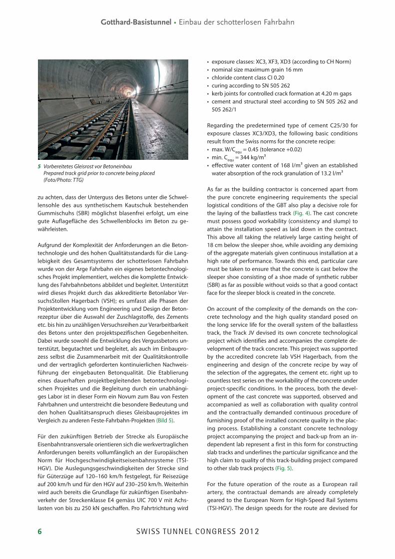
10 Das Herz des Betonzuges – Betonmischer mit Mischzentrale The heart of the concrete train – concrete mixer with central mixing unit (Foto/Photo: TTG)
Now the structural elements for the placing of concrete are installed, such as the structures for the drainage shafts, the surface drainage, etc. and at 4.20 m gaps the installation of the crack SCHWERTER + to cater for targeted crack forma-tion (kerb joints) in the cast concrete. The track grid is only then finely adjusted in the required position tolerance down to tenths of a millimetre using a laser-controlled surveying method (target panel) after the completion of all prepara-tory activities for the track. Then the track grid is ready for the concrete to be placed (Fig. 8).
7 Placing the concrete
The concrete train represents the core of the concrete plac-ing process. This trackbound mobile mixing plant transports the ready premixed aggregates with 1–16 mm grain size for a daily production of approximately 220 running metres of ballastless track into the tunnel in 15 wagons. Furthermore, there are 3 cement wagons and 1 water wagon with addi-tional capacity for additives (plasticiser) to produce the pre-determined concrete recipe. For operating the mixing plant, which is set up on its own flatbed wagon, there is also a workshop wagon for possible repair and maintenance work on the spot, a 16 kV power transformer wagon, so that the train can be connected to the medium-voltage network in the tunnel, a wagon with approximately 650 kVA emergency
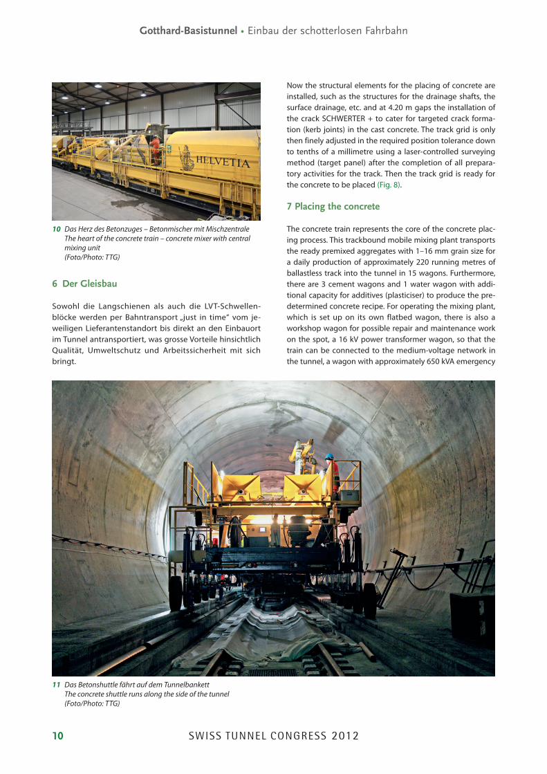
11 Das Betonshuttle fährt auf dem Tunnelbankett The concrete shuttle runs along the side of the tunnel (Foto/Photo: TTG)
SWISS TUNNEL CONGRESS 2012 11
Gotthard Base Tunnel • Installation of the Ballastless Track
Für die Montage des Gleisrostes und zur Erreichung der ge-forderten Lagegenauigkeit wurde eine 3-gliedrige Maschi-nengruppe (Gleisbauroboter) entwickelt, die die Schienen vom Hilfsgleis hebt, präzise auf Spurweite hält, danach den mechanisierten Einbau der Schwellenblöcke durchführt und zum Schluss den Schienen-Schwellen-Strang hochpräzise in die geforderte Neigung von 1:40 bringt und stabil hält. Durch die Montage eines hochpräzisen Stützsystems wird die eingestellte Spurweite und Schienenneigung gewähr-leistet und die endgültige Lage des Gleisrostes bereits milli-metergenau erreicht.
Jetzt erfolgt der Einbau der konstruktiven Elemente für den Betoneinbau, wie z. B. die Konstruktion für die Entwässe-rungsschächte, die Oberflächenentwässerung etc. und im Abstand von jeweils 4.20 m der Einbau der Rissschwerter zur gezielten Rissbildung (Kerbfugen) im Vergussbeton. Erst wenn alle vorbereitenden Arbeiten im Gleis abgeschlossen sind, erfolgt die Feinjustierung des Gleisrostes in die gefor-derte zehntelmillimetergenaue Lagetoleranz mittels laser-gesteuertem Vermessungsverfahren (Zieltafel). Danach ist der Gleisrost fertig für den Betoneinbau (Bild 8).
7 Der Betoneinbau
Das Kernstück des Betoneinbaus ist der Betonzug. Als ein auf Schienen fahrbares Mischwerk transportiert er in 15 Wag-gons die fertig vorgemischten Zuschlagstoffe in der Körnung 1–16 mm für eine Tagesproduktion von ca. 220 Laufmeter schotterlose Fahrbahn mit in den Tunnel. Hinzu kommen 3 Zementwaggons und 1 Wasserwaggon mit zusätzlicher Ka-pazität für Additive (Fliessmittel) zur Herstellung der festge-legten Betonrezeptur. Zum Betrieb des Mischwerkes, das auf einem eigenen Flachwaggon aufgebaut ist, gehört weiterhin ein eigener Werkstattwagen für allfällige Wartungs- und Re-paraturarbeiten vor Ort, ein 16 kV Strom-Transformator-Wa-gen, damit der Zug an das Mittelspannungsnetz des Tunnels angeschaltet werden kann, ein Wagen mit ca. 650 kVA Not-stromaggregatleistung für den Fall eines Stromunterbruchs, 1 Betonabfallwaggon, damit im Falle von Ereignissen nicht verarbeitbarer Beton wieder mit aus dem Tunnel genommen werden kann, sowie ein Pumpwaggon, mit dem der Beton auf das Betonshuttle verladen werden kann (Bild 9).
Die Betonproduktion vor Ort im Tunnel hat grosse Vorteile. So wird „just in time“ immer nur so viel Beton produziert, wie auch aktuell verarbeitet werden kann. Auf Unterbrüche beim Einbau kann beinahe verzuglos reagiert werden. Weiterhin wird immer frischer Beton produziert, der auch in seiner natürlichen „Lebenszeit“ verbaut werden kann. Besondere Massnahmen zur Steuerung der Lebensdauer des Betons (Verzögerer, Beschleuniger etc.) werden dadurch nicht not-wendig, der Einsatz von Chemie wird auf ein Mindestmass (Einsatz eines Fliessmittels) beschränkt. Für die gesamte Dauer des Betoneinbaus bleibt das hinter dem Betonzug liegende fertiggestellte Gleis frei und ist verfügbar für an-dere Gewerke und deren Ausbauarbeiten. Nur zum Schicht-
power aggregate capacity, should there be a power failure, 1 concrete waste wagon, so that unprocessed concrete can be removed from the tunnel as well as a pump wagon, which can load the concrete on to the concrete shuttle (Fig. 9).
Producing concrete on the spot in the tunnel is highly ad-vantageous. As a result, only as much concrete is produced “just in time” as can actually be processed. Any interruptions to installation can be reacted to practically without difficulty. Furthermore, fresh concrete is always being produced, which can also be placed during its natural “lifetime”. Special meas-ures to control the lifetime of the concrete (retarder, acceler-ator, etc.) are thus not required; the application of chemistry is restricted to a minimum (use of a plasticiser). The complet-ed track behind the concrete train remains free for the entire duration of the concrete placing process and can be made use of for other jobs and any support operations. However, manpower has to be transported when there is a change of shift for the concreting crew, although the concrete train it-self remain on site in the tunnel and can continue to operate without any delay (Fig. 10).
As the concrete train is only allowed to travel over the com-pleted track once the freshly concreted section has reached its minimal strength (approximately 48 h after placing the concrete), the concrete must be transported from the mix-ing plant to the point of installation. In order to protect the positional stability of the track as well as on account of the required installation capacity, the application of concrete pump lines does not make sense. As a consequence, a spe-cial concrete shuttle was developed which is driven electro-hydraulically, travelling on rubber wheels at the side of the tunnel (Fig. 11).
At the point of installation, the cast concrete is placed using a concrete distributor, which is charged from the concrete transporter, and an installation platform. The distributor’s ca-pacity is designed in such a fashion that the shuttle always has sufficient time for a transport cycle even given the great-
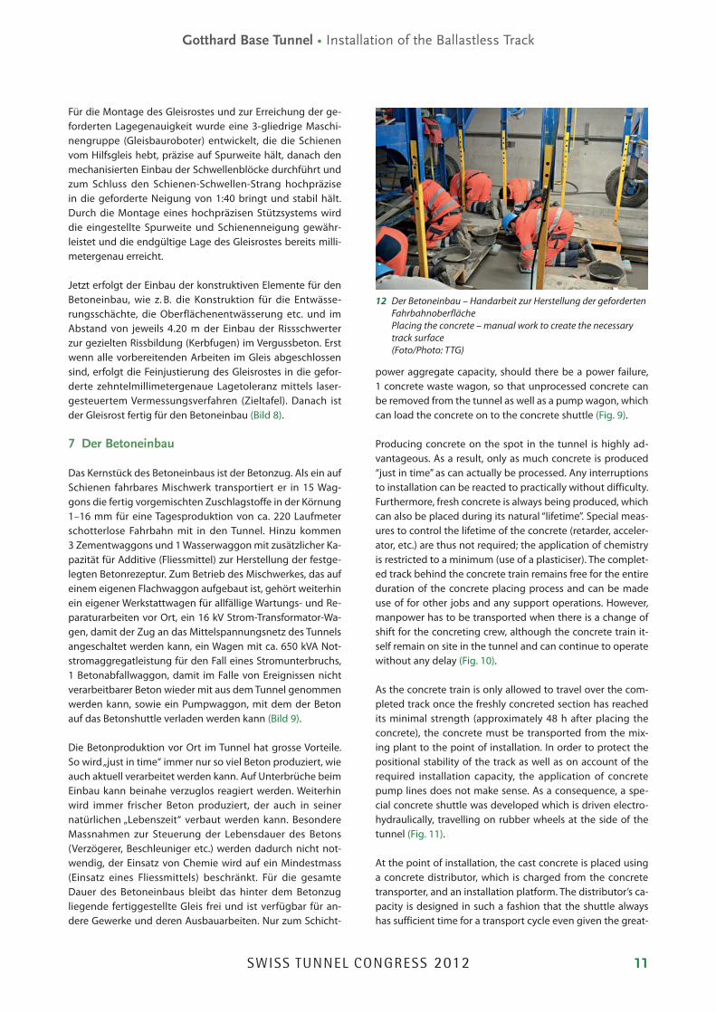
12 Der Betoneinbau – Handarbeit zur Herstellung der geforderten Fahrbahnoberfläche Placing the concrete – manual work to create the necessary track surface (Foto/Photo: TTG)

SWISS TUNNEL CONGRESS 201212
Gotthard-Basistunnel • Einbau der schotterlosen Fahrbahn
wechsel der Betonmannschaft muss ein Personentransport durchgeführt werden, der Betonzug selbst bleibt jedoch vor Ort im Tunnel und kann verzuglos weiterbetrieben werden (Bild 10).
Da der Betonzug das fertiggestellte Gleis erst nach Erreichen der Mindesthärte des frisch betonierten Abschnitts befah-ren darf (ca. 48 Stunden nach Betoneinbau), muss der Beton vom Mischwerk zum Einbauort transportiert werden. Zum Schutz der Gleislagestabilität, aber auch wegen der gefor-derten Einbauleistung ist der Einsatz von Betonpumplei-tungen nicht sinnvoll. Deshalb wurde ein spezielles Beton-shuttle entwickelt, das elektro-hydraulisch angetrieben ist und mit Gummi rädern auf dem seitlichen Tunnelbankett fährt (Bild 11).
Am Einbauort wird der Vergussbeton mittels einer Beton-verteilstation, die vom Betontransporter beschickt wird, und einer Einbauplattform eingebaut. Die Kapazität der Verteil-station ist so ausgelegt, dass das Shuttle immer genügend Zeit für einen Transportumlauf auch bei grösstmöglicher Entfernung zwischen Betonzug und Einbauort, maximal ca. 800 m, hat.
Die Betoneinbaumannschaft ist für einen kontinuierlichen, möglichst blasenfreien Einbau des Vergussbetons verant-wortlich. Für die Oberflächenentwässerung ist ein Quer-gefälle der Fahrbahn von 0.7 Grad Neigung herzustellen.
est possible distance between the concrete train and the point of installation, max. approximately 800 m.
The concrete placing crew is responsible for continuous in-stallation of the cast concrete as void-free as possible. A lateral gradient with an incline of 0.7° for the track has to be created for the surface drainage. This measurement accuracy and the necessary surface treatment of the concrete between the sleeper bays and beneath the rails call for the application of skilled manual labour by the finishing crew (Fig. 12).
8 Maintenance and technology
The application of such complex technologies requires the machines and equipment to be constantly maintained and kept running, something which is only possible during the night shift on account of the continuous production pro-cess. Whereas the track construction robots and the concrete placing machines are cleaned, serviced and repaired in the tunnel, the concrete train leaves the tunnel once the late shift is over and is cleaned and filled again in the rail vehicle hall on the installation yard (Fig. 13).
In addition, all aggregates for roughly 4 days of production are temporarily stored in the rail vehicle hall so that supplies are secured in the event of interruptions of a logistical na-ture. All mass materials are delivered via rail logistics.
13 Die Fahrbahnhalle – Materialumschlagplatz und Wartungs- und Instandhaltungswerkstatt The rail vehicle hall – material handling yard and repair and maintenance workshop (Foto/Photo: TTG)

SWISS TUNNEL CONGRESS 2012 13
Gotthard Base Tunnel • Installation of the Ballastless Track
Diese Massgenauigkeit und die notwendige Oberflächen-behandlung des Betons zwischen den Schwellenfächern und unter den Schienen erfordern den Einsatz von reiner fachmännischer Handarbeit durch die Taloschiergruppe (Bild 12).
8 Wartung und Technik
Der Einsatz derart komplexer Technologien erfordert eine stetige Wartung und Instandhaltung der Maschinen und Ge-räte, was aufgrund des kontinuierlichen Produktionsprozes-ses immer nur in der Nachtschicht erfolgen kann. Während im Tunnel die Gleisbauroboter und die Betoneinbaumaschi-nen gereinigt, gewartet und instandgesetzt werden, verlässt der Betonzug nach Ende der Spätschicht den Tunnel und wird in der Fahrbahnhalle auf dem Installationsplatz gerei-nigt und wieder beladen (Bild 13).
In der Fahrbahnhalle werden ausserdem sämtliche Zuschlag-stoffe für ca. 4 Produktionstage zwischengelagert, um bei logistischen Unterbrüchen Versorgungssicherheit zu ge-währleisten. Sämtliche Massengüter werden mittels Bahn-logistik antransportiert.
9 Fazit
Die Arge Fahrbahn konnte im Einbauabschnitt Faido-Bodio West die Leistungsfähigkeit des speziell für das GBT-Projekt entwickelten Einbauprozesses mit Erfolg unter Beweis stel-len. Der erste Einbauabschnitt von 15 040 m schotterloser Fahrbahn (Faido – Bodio West) ist planmässig – auf den Tag genau – erfolgt. Die letzten Meter wurden zeitgleich mit dem letzten Hauptdurchstich der Weströhre des GBT zwi-schen Faido und Sedrun am 23. März 2011 fertiggestellt (Bild 14). Aus der Planung wurde Realität:• Der Einbauprozess hat sich bewährt, der hohe Technisie-
rungsgrad trägt massgeblich zur Herstellung der geforder-ten Produktqualität und der Arbeitssicherheit und Gesund-heit der Mitarbeiter bei.
• Die Einsatzfähigkeit und Belastbarkeit der komplett neu entwickelten Maschinen hat sich bewährt und konnte unter Dauerlast nachgewiesen werden.
• Das Zusammenspiel Mensch und Maschine hat sich gefes-tigt, eine Linienbaustelle mit industriellem Fertigungscha-rakter wurde entwickelt.
• Die geforderte Qualität des Produktes Feste Fahrbahn Typ LVT im GBT mit den extrem engen Toleranzvorgaben des Werkvertrages konnte durchgängig und nachhaltig herge-stellt werden.
• Die Gebrauchstauglichkeit und Langlebigkeit des Sys-tems Feste Fahrbahn GBT konnte auf dem fertiggestellten Abschnitt Faido – Bodio West durchgängig nachgewiesen werden.
9 Summary
The Track JV was able to successfully prove the capability of the installation process especially developed for the GBT project in the Faido – Bodio West placing section. The first installation section of 15,040 m of ballastless track (FaidoBodio West) was completed according to schedule – to the very day. The final metres were completed simultaneously with the last main breakthrough of the GBT’s western bore between Faido and Sedrun on 23 March 2011 (Fig. 14). Planning became reality:• The installation process proved itself with the high degree
of engineering, essentially contributing to creating the de-sired product quality as well as industrial safety and health of the workforce.
• The availability and durability of the completely newly developed machines proved itself and was verified under constant load.
• Interaction between man and machine was consolidated; a line construction site with industrial production charac-ter was developed.
• The required quality of the product slab track Type LVT in the GBT with the extremely narrow tolerances contained in the works contract was created continuously and sustain-ably.
• The suitability for use and longevity of the GBT slab track system was proved continuously on the completed Faido – Bodio West section.
14 23. März 2011: Einbaumannschaft der letzten Meter schotterloser Fahrbahn im Abschnitt Faido – Bodio West 23 March 2011: crew installing the last few metres of ballastless track in the Faido – Bodio West section (Foto/Photo: TTG)