
St. Galler Angewandtes Management Zertifikat für Junior Manager im Schwerpunkt Digital Strategy

Drei Module für angewandtes Lernen von Computernetzwerken
Projektarbeit der Philosophisch-naturwissenschaftlichen Fakultät
der Universität Bern
Vorgelegt von: David Jud
Leiter der Arbeit: Prof. Dr. Torsten Braun
Betreuer der Arbeit: Marc-Alain Steinemann
Forschungsgruppe Rechnernetze und verteilte Systeme (RVS)
Institut für Informatik und angewandte Mathematik
2001, 2003

0 Table of Contents
0 Table of Contents.....................................................................................1
1 Abstract............................................................................................................3
2 Introduction..................................................................................................3
3 Concept of the Modules .....................................................................4 3.1. Structure......................................................................................................4 3.2. The Modules .............................................................................................4
3.2.1. Module 2: Configuring IP-based Ethernets and Routers ......................4 3.2.2. Module 3: Virtual Private Networks and Network Management .........4 3.2.3. Module 7: RPC, XDR (Remote Procedure Calls / External Data Representation), Sockets .......................................................................................5
4. The modules (original numbering).........................................5 Laboratory 2 ............................................................................................................6
2.1 Comments........................................................................................7
2.2 Pre Lab Work ................................................................................8 2.2.1 Recommended Reading.............................................................8 2.2.2 Must Reading ..................................................................................8 2.2.3 Exercises ...........................................................................................9
2.3 Lab Work .........................................................................................10
2.4 Post Lab Work ...........................................................................13
2.5 Solutions ..........................................................................................14 2.5.1 Pre Lab Work.................................................................................14 2.5.2 Lab Work .........................................................................................15 2.5.3 Post Lab Work...............................................................................17
2.6 Feed Back Form for Lab 2 .............................................18
A 2 Appendix .........................................................................................19 A 2.1 Cisco .................................................................................................19 A 2.2 Useful Cisco Commands .........................................................20
Laboratory 3 ..........................................................................................................21 3.1 Comments......................................................................................22
3.2 Pre Lab Work ..............................................................................23 3.2.1 Recommended Reading...........................................................23 3.2.2 Must Reading ................................................................................24 3.2.3 Exercises .........................................................................................24
1

3.3 Lab Work .........................................................................................25
3.4 Post Lab Work ...........................................................................27
3.5 Solutions ..........................................................................................28 3.5.1 Pre Lab Work.................................................................................28 3.5.2 Lab Work .........................................................................................30 3.5.3 Post Lab Work...............................................................................31
3.6 Feed Back Form for Lab 3 .............................................33
A 3 Appendix .........................................................................................34 A 3.1 VLAN ................................................................................................34 A 3.2 VPN ...................................................................................................34 A 3.3 SNMP ...............................................................................................35
Laboratory 7 ..........................................................................................................51 7.1 Comments......................................................................................52
7.2 Pre Lab Work ..............................................................................53 7.2.1 Recommended Reading...........................................................53 7.2.2 Must Reading ................................................................................53 7.2.3 Exercises .........................................................................................54
7.3 Lab Work .........................................................................................55
7.4 Post Lab Work ...........................................................................57
7.5 Solutions ..........................................................................................58 7.5.1 Pre Lab Work.................................................................................58 7.5.2 Lab Work .........................................................................................59 7.5.3 Post Lab Work...............................................................................67
7.6 Feed Back Form for Lab 7 .............................................69
A 7 Appendix .........................................................................................70 A 7.1: Socket Skeletons .......................................................................70 A 7.2: RPC Definition.............................................................................71 A 7.3: RPC Skeletons............................................................................72
2

1 Abstract The three modules in this report have been made for the “Computernetze Praktikum” (“Computer Networks Laboratory”) of the University of Berne, a practical training which was first held in spring 2001. The goal of this laboratory was to teach students how to install and configure IP based networks, mostly using Linux. Since this was a practical course, the focus was on checking out and applying things students only know from theory. The laboratory has greatly changed in the two years since it was first held, but the scope of this report is the laboratory as it was originally held back in 2001.
2 Introduction Students are supposed to work in small groups of 2-3 persons in the hands-on sessions. The laboratory takes place in a big room in the IAM (Institut für Informatik und angewandte Mathematik). The available hardware consists of: 8 Sparc 4 machines, 2 Cisco routers, 2 switches, 2 repeaters, various network cables (RJ45, some crossed, some straight), and other material such as books etc. This generally allows two groups to work at the same time, with the exception of modules 2 and 3 which require both Cisco routers. The operating system used is Debian GNU/Linux version 2 (“potato”). The estimated time spent in a module is 5 hours. Since a semester consists of 14 weeks, the students have 2 weeks available for most of the modules. Some modules build on the skills the students learn in other modules, which has to be considered when looking at the modules presented here: Module 2 depends on module 1 (“Building Ethernet-IP-Subnets with Repeaters and Switches”) which is not contained in this report, and module 3 is an extension of module 2. In contrast, module 7 is a module of its own and to some degree even independent of the hardware or operating system; actually, it was developed on Solaris and later migrated to Debian, which shows up in some comments of the skeleton files. Putting these modules in a context also requires looking at the intended audience: Students of Computer Sciences in at least their third year that have visited the lecture “Computernetze” (“Computer Networks”). So, the theoretical knowledge of computer networks and its basic technologies (TCP/IP, Ethernet, routing…) can be assumed as known, which is the reason these things are not explained in the documentation of the modules. On the other hand, it is astonishing how many students actually never have built a network before: When I visited the lecture “Computernetze”, less than 5 out of 25 students answered with “yes” to the assistant’s question if they ever had (the assistant was Marc-Alain Steinemann, by the way). To correct this disproportion between theoretical knowledge and practical experience is the main goal of the laboratory in my humble opinion.
3

3 Concept of the Modules 3.1. Structure Each module consists of three parts: Pre lab work, lab work, and post lab work. Pre lab work typically consists of material the students have to read to acquire the knowledge they will need (“Must Reading”), literature students may read to deepen their knowledge but do not have to (“Recommended Reading”), and some exercises. Students are supposed to make the pre lab work before entering the laboratory so they do not obstruct the hardware while looking up things they should know. Lab work usually consists of setting up the linux boxes, doing the actual practical training, and saveing to disk or printing some files that will be needed in post lab work. Post lab work usually consists of examining the collected data files, often allowing the students to state advantages and disadvantages of the used technology. 3.2. The Modules 3.2.1. Module 2: Configuring IP-based Ethernets and Routers The goal of module 2 is that students get familiar with the basics of Cisco routers and the software they are running: The Internet Operating System (IOS). To achieve this, students connect two computers with Cisco routers; the routers are connected to both each other and a third computer using a repeater. Every computer must be able to reach the other two computers. Cisco is the market leader, so the students get the most out of this lab if we use Cisco routers. 3.2.2. Module 3: Virtual Private Networks and Network
Management In module 3, students learn the basics of virtual private networks by simulating a typical use case: Two hosts connected over an insecure medium, for example two offices of the same company connected over the Internet. We pick up where we left in module 2. The computer connected to the repeater is able to monitor the data the routers are exchangeing. Students have to make sure the data the two routers exchange is encrypted and that the third computer can still be reached from the computers behind the routers (data sent to this computer will not be encrypted). They also have to quantify the impact encryption has on connection performance.
4

3.2.3. Module 7: RPC, XDR (Remote Procedure Calls /
External Data Representation), Sockets The goal of this module is to learn some basics of network programming, using two well known libraries: RPC and Sockets. To achieve this, students twice write the networked counterpart of a “Hello World” program, once with each library. Then they compare the two programs. They also try to create situations where the programs cease to function, for example by repeatedly starting and terminating them quickly, or by starting them when another instance is still running.
4. The modules (original numbering) The three modules are an excerpt of the Teachers Manual of the “Computernetze Praktikum”. Nothing has been changed (except for the page numbers of course), which is why it starts with chapter 2 and 3 and then jumps to chapter 7. Note that modules 4, 5 and 6 have been published in another report by their author: “Drei Module für das Praktikum Computernetzwerke”, Marco Studer, 2001.
5

Laboratory 2
Configuring IP-based Ethernets and Routers What you will learn in this lab: • How to configure Cisco 2620 and 3620 routers with Cisco IOS • How to route packets through an IP-based net
6

2.1 Comments - Only 1 group can work at the same time. - In this module, the routing techniques and mechanisms will be demonstrated with
Cisco routers. Routing is a very important topic and the routing principles must be understood. As Cisco is the market leader, students will have to work with Cisco routers to get a basic understanding on how to program and configure.
- Introduction into the new hardware:
• Routers
7

2.2 Pre Lab Work
2.2.1 Recommended Reading 1) General reading about network equipment like routers, switches and the Cisco
Internetworking operating system (IOS): http://www.cisco.com 2) Computernetzwerke, A. S. Tannenbaum, Prentice Hall, 1998, Die
Vermittlungsschicht, Chapter 5 3) TCP/IP Network Administration, O´Reilly, 1998, Chapters 5, 6, 7
2.2.2 Must Reading 1) Network Laboratory, Chapter 2 2) Introduction to the Routing Information Protocol (RIP)
http://www.cisco.com/univercd/cc/td/doc/cisintwk/ito_doc/rip.htm#xtocid194220, 4 pages
3) Computernetzwerke, A. S. Tannenbaum, Prentice Hall, 1998, Routing
Algorithmen, Chapter 5.2, page 375 – 403 4) TCP/IP Network Administration, O´Reilly, 1998, Configuring Routing, Chapter
7, page 164 – 200, Traceroute, 338 – 342
8

2.2.3 Exercises 1) How big is the LAN (MAC) address space? The Ipv4 address space? The Ipv6
address space? 2) Write a list of the most popular routing protocols and point out the specific
properties, advantages and disadvantages of RIP and OSPF. 3) Why is an ARP query sent within a broadcast frame? Why is an ARP response
sent within a frame with a specific destination address? 4) A router has at least two but often more interfaces. Per interface there is a ARP
module, each with its own ARP table. Is it possible that the same LAN address appears in more than one table?
9

2.3 Lab Work 1) Set up the machines as described in “Boot Procedure”. 2) Build a network following Figure 2.1. 3) Configure the Cisco routers with the IOS:
• Connect a laptop to the console interface of the router and use the terminal
emulation software “Hyperterminal” or another terminal software to interact with the router. The terminal configuration parameters: 9600 bauds, 8 data bits, no parity, 1 stop bit.
• Start the router and wait until the boot messages stop. • If it’s the beginning of the lab, erase the former configuration:
“erase nvram” <Return> “reload” <Return> You can repeat this procedure in case you want to start over…
• Configure the router. Look at table 2.3 to see in which mode you are. • Passwords:
(insist on “secret” as password, only in our lab you use the same password for the three modes. The two names of each password come from the different terminology Cisco uses.)
• secret password = enable secret: “secret” • privileged password = enable password: “secret” • virtual terminal password = unprivileged password: “secret”
• Names of the routers:
• Cisco 3620: labroutera10 • Cisco 2620: labroutera11
• Set your routers to RIP v2. RIP discovers automatically? and RIP needs info
about ? Hint: Interfaces need t be up. (no shutdown)
4) Configure the Linux machines.
10

5) Ping every host in your net. 6) Use traceroute to examine your connections. 7) Disable RIP. 8) Write your routing tables (static routing) in the routers. 9) Ping every host in your net, from host to host and from router to host. Retry but
use the command <debug ip packet> first. 10) Use traceroute to examine your connections. 11) Use netpipe to measure the bandwidth from one host to another host, connected
over the two routers. Connect the routers in exercise 10 with a crossover cable without repeater in between. Make graphics of your results.
12) Same as in 10) but now connect the routers through a repeater. 13) Same as in 10) but now connect the routers through a switch. 14) Print out the routing tables for the Post Lab Work!
11

igure 2.1: Network Topology with IP Addresses in Lab 2.
Machine OS Hostname H CIDR-IP Login Pass
A3
30.0.0.10 /8
A10 A11
Cisco Routers
A1
10.0.0.10 /8
Repeater20.0.0.1 /8
10.0.0.1 /8
20.0.0.2 /8
30.0.0.1 /8
A2
20.0.0.10 /8 F
FQA1 D laba1. be.ch 1 ebian laba1 cnl.uni 0.0.0.10/8 root fai A2 Debian laba2 laba2.cnl.unibe.ch 20.0.0.10/8 root fai A3 Debian laba3 laba3.cnl.unibe.ch 30.0.0.10/8 root fai
10.0.0.1/8 A10 IOS labr 10 labr ch s outera outera10.cnl.unibe.20.0.0.1/8
ecret
20.0.0.2/8 30.0.0.1/8
A11 IOS labroutera11 labroutera11.cnl.unibe.ch secret
able 2.1: The machines and their details T
12

2.4 Post Lab Work 1) Take the printouts of the routing tables of your experiments and describe the
entries, what they mean and why they are there. 2) Many of the functions of Unix routers are integrated into the hardware in the
Cisco routers. Why?
13

2.6 Feed Back Form for Lab 2 • Complete the form after finishing the whole lab and hand it to an assistant
at the beginning of the next lab. • You do not need to write your name on the form. • You can answer in English or in German. 1. Please rate the following: 4=Strongly Agree 3=Agree 2=Disagree 1=Strongly Disagree 4 3 2 1 The learn effect of this module was high.
The knowledge/skills learned will be useful to me.
The module came up to my expectations.
The formulation of the tasks was clear.
There were enough resources available to solve the lab work.
The exercises in the pre lab work helped me to work on the lab work.
2. Please answer the following questions: How might this module be improved? ________________________________________________________________________________________________________________________________________________________________________________________________________________________________________________________________________________ How much time did you spend for the whole module? ______________ Additional comments: ____________________________________________________________________________________________________________________________________________________________________________________________________________
18
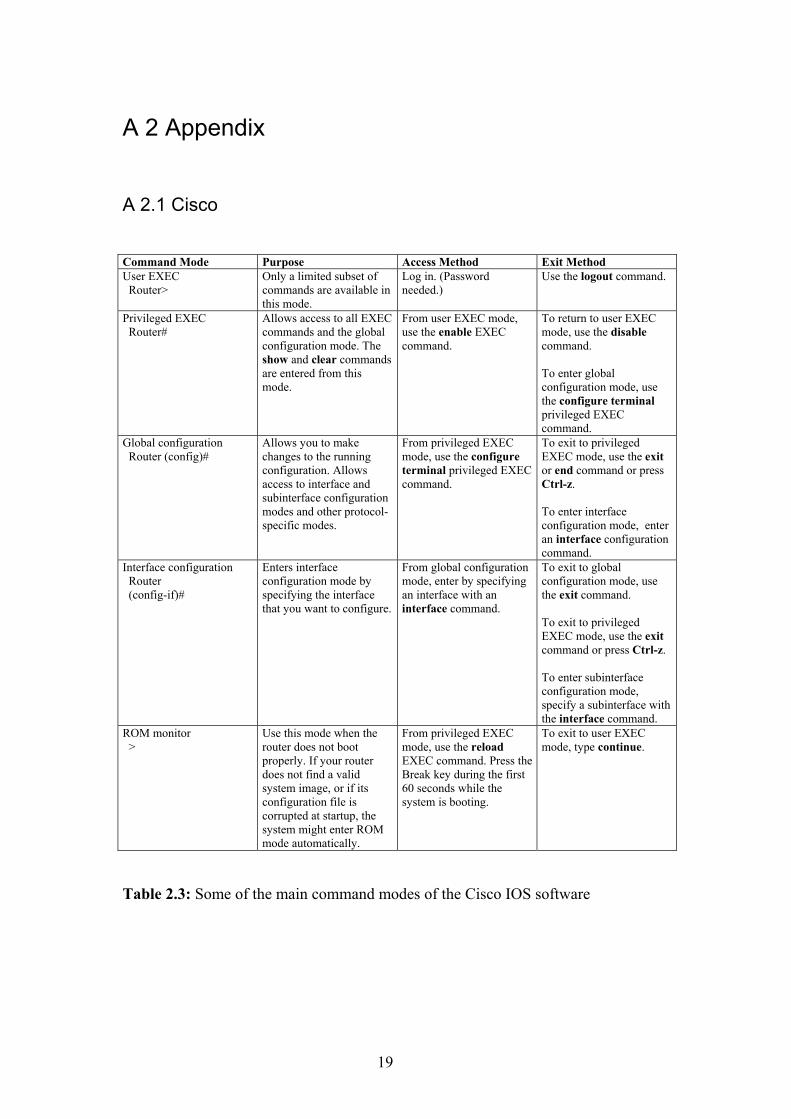
A 2 Appendix
A 2.1 Cisco
Command Mode Purpose Access Method Exit Method User EXEC Router>
Only a limited subset of commands are available in this mode.
Log in. (Password needed.)
Use the logout command.
Privileged EXEC Router#
Allows access to all EXEC commands and the global configuration mode. The show and clear commands are entered from this mode.
From user EXEC mode, use the enable EXEC command.
To return to user EXEC mode, use the disable command. To enter global configuration mode, use the configure terminal privileged EXEC command.
Global configuration Router (config)#
Allows you to make changes to the running configuration. Allows access to interface and subinterface configuration modes and other protocol-specific modes.
From privileged EXEC mode, use the configure terminal privileged EXEC command.
To exit to privileged EXEC mode, use the exit or end command or press Ctrl-z. To enter interface configuration mode, enter an interface configuration command.
Interface configuration Router (config-if)#
Enters interface configuration mode by specifying the interface that you want to configure.
From global configuration mode, enter by specifying an interface with an interface command.
To exit to global configuration mode, use the exit command. To exit to privileged EXEC mode, use the exit command or press Ctrl-z. To enter subinterface configuration mode, specify a subinterface with the interface command.
ROM monitor >
Use this mode when the router does not boot properly. If your router does not find a valid system image, or if its configuration file is corrupted at startup, the system might enter ROM mode automatically.
From privileged EXEC mode, use the reload EXEC command. Press the Break key during the first 60 seconds while the system is booting.
To exit to user EXEC mode, type continue.
Table 2.3: Some of the main command modes of the Cisco IOS software
19

A 2.2 Useful Cisco Commands Showing Routing Info in enable mode show ip route Save config in enable mode copy running-config startup-config Erase config in enable mode erase nvram reload Flash new IOS (NOT FOR STUDENTS!!!!) in enable mode copy tftp flash filename: c3620-ik2o3s-mz.120-7.T.bin Packet tracing labb1:~# traceroute -dFlurv 20.0.0.1 1500 traceroute to 20.0.0.10 (20.0.0.10), 30 hops max, 1500 byte packets 1 30.0.0.1 36 bytes to 30.0.0.10 2.813ms 2.672ms 2.631ms 2 20.0.0.10 492 bytes to 30.0.0.10 6.465ms 6.433ms 6.382ms Resources http://www.cisco.com/univercd/cc/td/doc/product/software/ios111/mods/
20

Laboratory 3
Virtual Private Networks and Network Management What you will learn in this lab: • Implementation of a VPN with Cisco routers • Network Management Methods
21

3.1 Comments - Only 1 group can work per time slot. - VPN are used to interconnect private hosts or nets over public nets in a secure
way. Users are mostly not aware that they are connected through networks outside the proper LAN.
- Network management is an important task to maintain a net. The well-deployed
SNMP has big disadvantages, like a lack of security, limited alert and configuring capacity. There exist improvements but the problem is that manufacturers have not yet agreed to a common stanard. The next standard is SNMPv3.
22

3.2 Pre Lab Work
3.2.1 Recommended Reading 1) TCP/IP Network Administration, O´Reilly, 1998, Network Security, chapter 12 2) VPN, O´Reilly, 1995, Basic VPN Technologies, chapter 2, Creating a VPN
with the Unix Secure Shell, chapter 8, pages 11 – 42 and 135 – 160 3) VPN, O´Reilly, 1995 4) Building and Managing VPN, Dave Kosiur, Wiley, 1998 5) SNMP SNMPv2 and RMON, W. Stallings, Addison-Wesley, 1997 6) General reading about network management http://www.cisco.com 7) Layer 2 Tunneling Protocol
http://www.cisco.com/warp/public/cc/pd/iosw/prodlit/l2tun_ds.htm 8) Which VPN is right for you?
http://www.cisco.com/warp/public/707/which_vpn.html 9) SNMP hot tips page http://www.cisco.com/warp/public/477/SNMP/snmp-
indx.html 10) Cisco Secure http://www.cisco.com/warp/public/44/jump/secure.shtml 11) IBM VPN Overview http://www.networking.ibm.com/vpn/vpntech.html 11) SNMPv1…3 http://www.comsoc.org/pubs/surveys/4q98issue/stallings.html
23

3.2.2 Must Reading 1) Network Laboratory, Chapter 3 2) Configuring Network Data Encryption
http://www.cisco.com/univercd/cc/td/doc/product/software/ios113ed/113ed_cr/secur_c/scprt4/scencryp.htm
3) Cisco IOS SNMP Traps Supported and How to Configure Them
http://www.cisco.com/warp/public/477/SNMP/snmp_traps.html 4) Simple Network Management Protocol
http://www.cisco.com/univercd/cc/td/doc/cisintwk/ito_doc/snmp.htm 5) Remote Monitoring (RMON)
http://www.cisco.com/cpress/cc/td/cpress/fund/ith2nd/it2451.htm 6) The NET-SNMP Home Page http://net-snmp.sourceforge.net/ 7) Appendix of Chapter 3
3.2.3 Exercises 1) Make a draw of an example configuration of SNMP with a management station,
host, router and MIB.
2) What are the basic components you encounter with SNMP?
3) Is SNMP really an optimal tool?
4) What are the problems you encounter when you need to implement a VPN and should pass a firewall?
5) Compare VLAN and VPN. What are they made for, where are they used, what do you need to implement…
6) SNMP messages are transported in unreliable UDP datagrams. Why do you think the designers chose UDP rather than TCP as the transport protocol of choice for SNMP?
24

3.3 Lab Work 1) Build a network following Figure 3.1. Make sure you use a repeater, not a
switch. (Why?) 2) Configure the Linux machines. Configure the Cisco routers with the IOS as you
did in lab 2, using RIP for routing. Ping every host in your net. 3) Measure the bandwidth between A1 and A3 using netpipe. Save the results for
post lab work. 4) Create users on A1, A2 and A3. Make telnet sessions between A1 and A3, in
both directions, using tcpdump on A2 to sniff the passwords. 5) Create DSS keys on the routers. Exchange the DSS keys. Configure the routers
to encrypt both TCP and UDP traffic between 10.0.0.0/8 and 30.0.0.0/8. 6) Make telnet sessions between A1 and A3, in both directions, trying to sniff the
passwords using tcpdump on A2. Verify if packet data is encrypted. Save the dump for post lab work.
7) Make telnet sessions between A2 and A1/A3, in all 4 directions to verify if the
routers really encrypt traffic between 10.0.0.0/8 and 30.0.0.0/8 only. 8) Measure the bandwidth between A1 and A3 using netpipe. Save the results for
post lab work. 9) Configure A10 to allow SNMP access, and to send traps to A1. 10) Use SNMPWALK to examine the SNMP fields of A10. What kind of
information can be found? Save the walk for post lab work. 11) Save the current configuration of A10 to nvram. Provoke a power interruption
on A10. Examine the traps A1 got. 12) Use SNMPWALK to get the fields of A10 again. Save the walk for post lab
work.
25

igure 3.1: Network Topology with IP Addresses in Lab 3, Cisco routers.
Machine OS Hostname H CIDR-IP Login Pass
A3
30.0.0.10 /8
A10 A11
Cisco Routers
A1
10.0.0.10 /8
Repeater20.0.0.1 /8
10.0.0.1 /8
20.0.0.2 /8
30.0.0.1 /8
A2
20.0.0.10 /8 F
FQA1 D laba1. be.ch 1 ebian laba1 cnl.uni 0.0.0.10/8 root faik A2 Debian laba2 laba2.cnl.unibe.ch 20.0.0.10/8 root faik A3 Debian laba3 laba3.cnl.unibe.ch 30.0.0.10/8 root fai
10.0.0.1/8 A10 IOS labr 10 labr ch s outera outera10.cnl.unibe.20.0.0.1/8
ecret
20.0.0.2/8 30.0.0.1/8
A11 IOS labroutera11 labroutera11.cnl.unibe.ch secret
able 3.1: The machines and their details T
26

3.4 Post Lab Work 1) Compare the netpipe results without encryption and with encryption. What
could be done to increase the bandwidth with encryption? 2) Which information is encrypted by Cisco routers? Use the saved tcpdump resilts
to find out the answer. 3) Compare the SNMP fields of A10 before and after power interruption. Which
fields did change? 4) Where would you use VPN and where VLAN?
27

3.6 Feed Back Form for Lab 3 • Complete the form after finishing the whole lab and hand it to an assistant
at the beginning of the next lab. • You do not need to write your name on the form. • You can answer in English or in German. 1. Please rate the following: 4=Strongly Agree 3=Agree 2=Disagree 1=Strongly Disagree 4 3 2 1 The learn effect of this module was high.
The knowledge/skills learned will be useful to me.
The module came up to my expectations.
The formulation of the tasks was clear.
There were enough resources available to solve the lab work.
The exercises in the pre lab work helped me to work on the lab work.
2. Please answer the following questions: How might this module be improved? ________________________________________________________________________________________________________________________________________________________________________________________________________________________________________________________________________________ How much time did you spend for the whole module? ______________ Additional comments: ____________________________________________________________________________________________________________________________________________________________________________________________________________
33

A 3 Appendix
A 3.1 VLAN Frame identification or tagging is one approach for logically grouping users into administratively defined VLAN. Routers provide policy-based control, broadcast management, and route processing and distribution. They also provide the communication between VLAN and VLAN access to shared resources such as servers and hosts.
igure 3.A1: Cisco’s VLAN implementation with Catalyst Switches.
A 3.2 VPN
here are two main architectures for setting up a VPN tunnel: client-initiated or
to the client, the ISP's POP
F
Tclient-transparent. Client-initiated tunneling requires tunneling software both for clients and for tunnel servers (or gateways). The latter typically reside at the corporate central site, though they could reside at the ISP POP that serves the central site. With client software to initiate the tunnel, and the tunnel server at the corporate site to terminate the tunnel, the ISP doesn't have to support tunneling in any way. The client and the tunnel server simply establish the tunnel, using authentication based on a user ID and password and perhaps on a digital certificate. The client and the tunnel server may also negotiate encryption. Once the tunnel is established, communications proceed as if the ISP were not mediating the connection. On the other hand, if you want tunneling to be transparentmust have tunnel-enabled access servers and perhaps routers. The client first dials in to the access server, which has to recognize (based on a user ID, for instance, or on the user's choice from a menu) that this connection should be tunneled to a particular remote location. The access server then establishes the tunnel with the tunnel server,
34

typically using the user ID and password for authentication. The client then establishes a session directly with the tunnel server via the tunnel, just as if the two were directly attached. While this has the advantage that no special software is required on the client, the client can dial only into properly equipped access servers. Full article
ervice Architecture Technologies SAccess VPN d ec, dial, xDSL, Client-initiate
NAS-initiated L2F/L2TP, IPsmobile IP, cable
IP tunnel Virtual CiMPLS
GRE, IPsec Frame RelayIP or IP and ATM
Intranet and Extranet VPN rcuit , ATM
able 3.A1: VPN Services and Architectures
A 3.3 SNMP
ser's Guide to CMU SNMP for Linux http://linux.dn.ua/docs/dp/cmusnmp.html
PORTANT! This guide should be considered a historical document. The SNMP
ontents
What is CMU SNMP?
py
Objects efinitions
ation
2 Administrative Model
tion
T
U IMv2 model described herein has been abandoned in favor of the USEC model. When time permits, I will update this guide to reflect the new reality. C Why This User's Guide? How To Get Your Own Co Brief Introduction to SNMP Model Implementation MIB MIB Adding MIB D SNMP v1 Configur Using snmpget Using snmpwalk Using snmpset traps SNMP v2 SNMP v Context Party Configura party.conf view.conf
35

context.conf
et
ptest sample program le
- Unresolved Questions
hat is CMU SNMP?
NMP (Simple Network Management Protocol) is an Internet standard for
freely downloadable implementation
s of April 1996, the current version of CMU SNMP is 2.1.2, and the most recent
ote: For whatever it may be worth, someone reported to your author that they tried
hy This User's Guide?
ecause in the words of the Linux port's README:
* manpages/docs: aeh, umm - beam me up
fact, the Linux port does come with a few, brief, man pages. But nothing that one
ow To Get Your Own Copy
TP to sunsite.unc.edu (or, preferably, one of its many mirrors) and cd into
he distribution provides easy to follow installation instructions.
acl.conf Using snmpg API snm GET_REQUEST examp SNMP2_TRAP example References Appendix A W Sexchanging network management information. CMU (Carnegie Mellon University) provides aof SNMP, which Juergen Schoenwaelder and Erik Schoenfelder ported to Linux. Aversion of the Linux port is 4 (giving 2.1.2l4). 2.1.2l4 requires kernel version 1.3.20 or later and libc 5.0.9 (ELF). Your author isn't running ELF (yet), so this guide is based on version 3 of the Linux port. But it should still apply to version 4. Nport 4 on kernel 1.2.13 and it seemed to work. W B Incould call a tutorial, HOWTO, etc. H F/pub/Linux/system/Network/admin. Get either (or both) cmu-snmp2.1.2l4-bin.tar.gz or cmu-snmp2.1.2l4-src.tar.gz. The l3 version is no longer available at sunsite. So, you can download the uuencoded-gzipped-tared source or binary version from this page. T
36

(For your reference, the original CMU code can be found at ftp.net.cmu.edu as
rief Introduction to SNMP
odel
he SNMP (version 1) model of network management consists of two kinds of
uch of the network management information an agent can provide has value in
plementation
NMP is implemented as a client/server (using UDP) which, at first blush, may seem
ost managers also provide individual (shell-level) commands which allow a user to
IB
he network management information provided by agents to managers is stored
.
-------------------
int-iso-ccitt(2)
/pub/snmp-dist/cmu-snmp2.1.2.tar.Z.) B M T"actors": a manager and an agent. An agent machine responds to requests for information from a manager machine. The manager requests information from the agent using a get-request to which the agent replies with a get-response. The manager can also send a set-request instructing the agent to update some piece of information in its database with the value provided by the manager. Communication between a manager and agent is commonly via this request/response exchange. However, an agent can provide unsolicited information to a manager by sending a trap. Mterms of security, that is, an attacker could make nefarious use of it. So, in an attempt to restrict who can retrieve an agent's information, the manager must provide a password known as the community name. When an agent receives a request, it checks the community name provided in the request with its own list of acceptable community names. If there's a match, the agent honors the request. Im Sslightly counterintuitive: the agent is server and the manager is the client. But, upon further reflection, this makes sense. The agent (server) machine runs a daemon called snmpd which continually listens for get- and set-requests from a manager. The manager (client) machine typically runs a sophisticated graphical application which uses get- and set-requests to perform tasks required by the human user. Mexecute a single get- or set-request. In CMU's implementation of SNMP, these commands are snmpget, snmpwalk, and snmpset. M T(logically) in the MIB (Management Information Base). The MIB is an enormous tree that provides a map for locating information. For example, here is but a small portion of the MIB: | ----------- | | | ccitt(0) iso(1) jo
37

| --------------------- | | | | org(3)
(6)
net(1)
mt(2)
-------------------------------
anslation(3) ip(4)
his diagram is based on version 1 of the MIB, which is now obsolete. The mib
he system node has several child nodes such as sysDescr, sysContact, sysName, and
he distinction between objects and instances becomes clear when we consider how
so.org.dod.internet.mgmt.mib-2.system.sysContact
ut to specify the value of sysContact on a particular agent machine, we use the
so.org.dod.internet.mgmt.mib-2.system.sysContact.0
he first node, iso, must have a leading dot to indicate that this path begins at the root
.3.6.1.2.1.1
stead of:
so.org.dod.internet.mgmt.mib-2.system
| dod | inter | mg | mib(1) | --------------------- | | | | system(1) interfaces(2) address tr (Tnode should, in fact, read "mib-2". Since CMU SNMP implements MIB-2, that's what we will use in this guide.) TsysLocation. These child nodes are called objects, and are depicted as leaf nodes in the MIB tree. This leaf node depiction is slightly misleading, however, because objects have no value in and of themselves. Rather, an object defines a type of value, and it is object instances which hold the value of a leaf node. Tto reference MIB information. To specify the sysContact object, we use the notation: .i bnotation: .i Tof the MIB tree. Also, notice (in the MIB tree) that each node has a number in parenthesis next to the node name. This gives a concise alternative for specifying objects and instances. For example, to specify the system node (called the system group since it is the parent of all the system leaf nodes), we can use: .1 in .i
38
MIB Objects
he objects in the system group are known as scalar objects because they can have
o reference a value in a table object, we specify the MIB path to the column in the
so.org.dod.internet.mgmt.mib-2.interfaces.ifTable.ifEntry.ifDescr.1
ould give us the description of the first interface on the agent machine. We noted
terfaces.ifTable.ifEntry.ifDescr.1
his discussion barely scratches the surface of the SNMP protocol and the MIB. For
dding MIB Definitions
IBs are defined in a formal language called ASN.1 (Abstract Syntax Notation One).
MU SNMP comes with a rather intelligent parser which can convert ASN.1 into
owever, CMU does not have ASN.1 definitions for proprietary (vendor-specific)
hen collecting ASN.1 definitions from vendors, be sure you get all the definitions
Tonly one value at a time. In addition to scalar objects, the MIB also contains table objects. For example, the interfaces group consists of a single table (ifTable) whose only child is ifEntry. ifEntry's children are the column headings of the table, i.e. ifIndex, ifDescr, ifType, ifMtu, etc. Each column heading has as many children as there are rows in the table. Ttable followed by the row specifier. Using interfaces as an example: .i wabove the use of the leading dot to indicate the root of the MIB tree. As you can see, object instances tend to have very long paths. So, as a short cut we can omit the leading dot and just specify the path beginning with the child of the mib-2 node. For example: in Tall the details, you will need one of the references at the end of this guide. A MIn order for an SNMP manager (or agent) to use a MIB definition, it must convert the ASN.1 definition into some sort of internal format specific to the manager (or agent). This conversion is accomplished using a parser. CCMU's own internal format on the fly. CMU looks for the ASN.1 MIB definitions in a file called mib.txt, typically located in the /usr/lib directory. The default mib.txt file contains the ASN.1 definitions for all the commonly used standard MIBs. HMIBs. For example, suppose you want to monitor ports on a Synoptics Token Ring concentrator. To do so with CMU SNMP, you must add to mib.txt the ASN.1 definitions for this device. Many vendors publish the ASN.1 definitions of their proprietary MIBs on their Web sites. So, just use a Web browser and save a copy of the appropriate MIB definitions. Once you have the necessary definitions, simply append them to the mib.txt file. Wupon which some particular definition depends. For example, the SYNOPTICS-TOKENRING-MIB depends on several other MIBS, as you can see from the IMPORTS statement:
39

IMPORTS r, IpAddress, TimeTicks
-1212 ress
planeType
x ;
MU SNMP already has the definitions for RFC1155-SMI, RFC-1212, and
NMP v1
onfiguration
or SNMP v1, there is almost nothing to configure. The *.conf files (acl.conf,
ou might want to customize the private community name, system contact, system
OTE: Only two community names are available: public and private (or whatever
ow, you can start the snmpd daemon with:
sr/sbin/snmpd > /dev/null 2>&1 &
or simplicity, this guide assumes you have configured your machine as both an
sing snmpget
he snmpget command allows you to retrieve the value of a single MIB variable
mpget -v 1 hostname community_name MIB_object_instance
or example,
Counte FROM RFC1155-SMI OBJECT-TYPE FROM RFC DisplayString, PhysAdd FROM RFC1213-MIB SnpxChassisType, SnpxBack FROM SYNOPTICS-ROOT-MIB s3000TokenRing, s3CommonBoardInde FROM SYNOPTICS-COMMON-MIB CRFC1213-MIB. You would need to download SYNOPTICS-ROOT-MIB and SYNOPTICS-COMMON-MIB in order to use SYNOPTICS-TOKENRING-MIB. S C Fcontext.conf, party.conf, snmpd.conf, and view.conf) must all exist in the /etc directory, but snmpd.conf is the only one whose contents are read for v1 protocol activity. Ylocation, and system name, as well as comment out any unused interfaces. See snmpd.conf(5) for more details. Nname you use for the private community). N /u Fagent (running snmpd) and a manager (snmpget, etc). U Tfrom an agent when you know the exact MIB object instance (leaf node). The syntax is: sn F
40

snmpget -v 1 localhost public system.syscontact.0
trieves the name of the system contact from the local machine using the public
mpget -v 1 localhost cyrano system.syscontact.0
retrieve the same MIB object instance.
or more details, see snmpget(1).
sing snmpwalk
he snmpwalk command allows you to retrieve the value of one or more MIB
mpwalk -v 1 hostname community_name MIB_object_type
or example,
mpwalk -v 1 localhost public system.syscontact
trieves the name of the system contact from the local machine using the public
mpwalk -v 1 localhost cyrano system.syscontact
retrieve the same MIB object instance. Notice that this is different from using
e can also use snmpwalk to retrieve more than one variable's value. For example:
mpwalk -v 1 localhost public system
turns the values of all the variables under the system node in the MIB.
or more details, see snmpwalk(1).
sing snmpset
he snmpset command allows you to set the value of a single MIB variable. The
mpset -v 1 hostname community_name MIB_object_instance type value
or example,
recommunity name. If the private community name is cyrano (defined in /etc/snmpd), we can use the command: sn to F U Tvariables from an agent without having to specify the exact instance. The syntax is: sn F sn recommunity name. If the private community name is cyrano (defined in /etc/snmpd), we can use the command: sn tosnmpget because we didn't specify the '.0' instance identifier. W sn re F U Tsyntax is: sn F
41

snmpset -v 1 localhost cyrano system.syscontact.0 s [email protected]
t the name of the system contact to the string (type s) [email protected] using
or more details, including a complete list of types, see snmpset(1).
aps
MU SNMP provides a daemon called snmptrapd which allows a manager machine
s an alternative, another implementation of SNMP called scotty also provides a
NMP v2
NMP v2 is a great deal more complex than v1, and configuring snmpd to support v2
he advantage of SNMP v1 is its simplicity. Its administrative model
NMP v2 Administrative Model
NMP v2 extends the administrative model in two ways. First, it allows managers to
econd, SNMP v2 completely revamps security by replacing the community name with the context and other related concepts.
sethe private community name cyrano. The change is also recorded in the /etc/snmpd.conf file. Set requests using the public community name are not allowed. F tr Cto receive and log traps (logging is performed through syslogd). This implementation does not, however, provide a shell-level command to generate SNMP v1 traps from an agent machine. However, the snmptest command provides a mechanism for generating an SNMP v2 trap. Amechanism (using Tcl) for generating traps interactively. S Srequires a basic understanding of the v2 administrative model. The following discussion will suffice to enable you to create a minimal v2 configuration. However, we will gloss over many, many details. You really do need a copy of one of these books. T(manager/agent) is easy to understand, and the community name provides some measure of control over who can obtain MIB information. But the disadvantage of SNMP v1 is its simplicity. Its administrative model is insufficient for large networks, and the community name provides the smallest conceivable amount of control (an unencrypted password) over MIB access. Hence, a new version. S Sexchange information. This M2M (Manager to Manager) communication enables network administrators to create a hierarchy of management stations. Imagine a company with 20 interconnected networks, each in a different city, with a 500 machines per network. Under SNMPv1, a single management station would have to monitor 10,000 machines - not realistic. But under SNMP v2, each network can have its own management station which communicates with a central management station which, in turn, oversees the internetwork as a whole. We won't discuss M2M any more in this guide. S
42

The community name single-handedly communicates (from an analysis by Marshall Rose cited in [Stallings, pp 345-346]): the identity of the manager the identity of the agent
mation
t of view, the community name tries to communicate far o much information (resulting in communicating nothing reliably). So, SNMP v2
below has been set aside (in e formal Internet standardization process) in favor of the USEC model.
P v2 context is "a collection of managed object resources" [Stallings, p 45]). Essentially, "object resources" simply means "MIB information". However,
ontext is called a proxy relationship.
v2 introduces the party concept to clarify who does what for whom. By alling an SNMP entity (manager, agent, or proxied machine) a party, we're
|--> Privileges --------->|
|--> IP Address |
the location of the MIB infor authentication information access control information MIB view information From a security design pointocommunicates each of these pieces of information separately, permitting greater flexibility and as well as protection of MIB information. The reader should note that the party model overviewed thUnfortunately, CMU SNMP does not currently support the USEC model. For more information on USEC see The Simple Times. Context An SNM3MIB information comes in two varieties: information stored on the agent machine, and information stored on some other machine (e.g. a machine that doesn't support SNMP) for whom the agent is acting as a proxy. If the MIB information is on the agent machine, the context called a MIB view. If the information comes from a proxied machine, the cThis is how SNMP v2 distinquishes the location of the MIB information (recall Rose's list above). We won't discuss proxy relationships any further in this guide. Party SNMPcemphasizing the role it plays [Stallings, p 225]. For example, a single agent can play one roll when interacting with manager A, but a different roll when interacting with manager B. The agent plays different rolls by providing different kinds of access (read or write) to different subtrees (i.e. views) of the MIB tree. Let's clarify all these ideas with a picture: |--> Get | |--> Set | | | |
43

|--> Destination Party -->|--> Privacy Keys
|--> IP Address |
acy Keys
|--> MIB View > Context ------------>|
ionship
model is a tree whose root is an access ontrol list (ACL). The ACL contains multiple entries, each of which specifies:
who will take the action (Destination Party) t)
ared to take for the Source Party
two parties can communicate secretly using the Privacy Keys. The two arties can also mutually authenticate each other (be certain of the other's identity)
u need to proceed with configuring CMU's SNMP 2.
figuration
P package contains four configuration files that are specific to SNMP 2. They are:
defines IP address, privacy and authentication keys of the parties view.conf - defines MIB subtrees
h a context and a set of privileges
lowing two definitions to your /etc/party.conf file:
| | | |--> Authentication Keys | ACL -->| | | |--> Source Party ------->|--> Priv | | | |--> Authentication Keys | | | |-- |--> Proxy Relat Conceptually, the SNMP v2 administrative c who is requesting that action be taken (Source Party) upon what information will the action be taken (Contex what actions the Destination Party is prep(Privileges) If needed, thepusing the Authentication Keys. SNMP v2 is designed to use DES encryption for privacy and the MD5 digest algorithm for authentication. We will not discuss in this guide how to use DES and MD5. You now have the basic ideas yov Con The CMU SNMv party.conf - context.conf - defines the MIB view or proxy relationship for each context acl.conf - associates two parties wit Let's see how to setup the simplest possible configuration. party.conf Add the fol
44

robin .1.3.6.1.6.3.3.1.3.127.0.0.1.5 snmpUDPDomain 127.0.0.1 161
000000000000000000000000 Null 0000000000000000000000 Null
snmpUDPDomain 0.0.0.0 0
000000000000000000000000 Null 0000000000000000000000 Null
er) and robin (the agent). They will ommunicate with no authentication (noAuth) or privacy (noPriv). robin and batman
nce, the path where parties are defined (.1.3.6.1.6.3.3.1.3) expands to:
lowing two lines to your /etc/view.conf file:
3 .iso.org.dod.internet.mgmt.mib-2.system.sysContact included Null
ct object and othing else.
wing definition to your /etc/context.conf file:
3 Null currentTime
ays that batcave is the third context defined on the local machine ote the last digit on the object ID), and that this context refers to MIB view number
6.1.6.3.3.1.4) expands :
noAuth noPriv 300 484 29F660EA 00000000 0000000000 batman .1.3.6.1.6.3.3.1.3.127.0.0.1.6 noAuth noPriv 300 484 29F660EA 00000000 0000000000 Now we have two new parties, batman (the managcare the fifth and sixth (respectively) parties defined on on the local system (note the last digit in their object IDs). And the 127.0.0.1 indicates that the party is located on the local host. For your refere .iso.org.dod.internet.snmpV2.snmpModules.partyMIB.partyAdmin.initialPartyID view.conf Add the fol 3 .iso.org.dod.internet.mgmt excluded Null We now have a new view (view number 3) which contains the sysContan context.conf Add the follo batcave .1.3.6.1.6.3.3.1.4.127.0.0.1.3 0 0 0 This definition s(n3. The three zeros indicate that this is not a proxy relationship. For your reference, the path where contexts are defined (.1.3.to
45

.iso.org.dod.internet.snmpV2.snmpModules.partyMIB.partyAdmin.initialContextID
ollowing line to your /etc/acl.conf file:
e destination party) is prepared to get (G) information om the batcave for batman (the source party).
mmand allows you to retrieve the value of a single MIB variable om an agent when you know the exact MIB object instance (leaf node). The syntax
pget -v 2 hostname src_party dest_party context MIB_object_instance
t hostname src_party dest_party context MIB_object_instance
following the xamples above):
batman robin batcave system.syscontact.0
chine using the batcave ontext. But if we use:
an robin batcave system.sysdescr.0
Such Object available on this agent
t(1). Note, however, the context is quired (the man page is in error).
PI
MU SNMP package provides an C language API. Like the rest of the package, s documentation is minimal. See the ./cmu-snmp2.1.2l3/snmplib/snmp_api.h file for
acl.conf Add the f robin batman batcave G This line says that robin (thfr Using snmpget The snmpget cofris: snm or just snmpge For example (assuming you have configured your SNMP files e snmpget localhost retrieves the name of the system contact from the local mac snmpget localhost batm the snmpd daemon replies: system.sysDescr.0 = No because sysdescr is not in the batcave context. For more details, see the man page snmpgere A The Cit
46

a description of the various functions available. The snmp_api man page is in the original CMU distribution, but not the Linux port. In terms of sample programs which use the API, see the ./cmu-snmp2.1.2l3/apps
irectory. In particular, the snmptest.c program illustrates how to send various PDUs.
(which comes with the original but not the Linux istribution) is very incomplete. So, this section will present the program options.
us NMP PDUs. It has the following invocation syntax:
r snmptest [ -v 2 ] [ options ] hostname noAuth dstParty context
nd outgoing packets -p portnum, specify destination port number
ou are presented with the Variable: prompt at which you an specify an object ID, or an snmptest command. The available commands are:
$D, toggle packet dumping on/off
U PDU
_TRAP PDU
prompted for two more pieces of information. irst, the Type [i|s|x|d|n|o|t|a]:, meaning:
s, STRING
ESS
d snmptest sample program The snmptest man paged snmptest is an interactive, command line-driven, program for generating varioS snmptest -v 1 [ options ] hostname community oor snmptest [ -v 2 ] [ options ] hostname srcParty where the options are: -d, dump incoming a -t timeout, specify timeout -r retry, specify retry -c clock, specify clock Once the program begins, yc $B, specify BULK_TRANSFER_REQUEST PDU $G, specify GET_REQUEST PDU $I, specify INFORM_REQUEST PD $N, specify GET_NEXT_REQUEST $Q, quit snmptest $S, specify SET_REQUEST PDU $T, specify SNMP2 If you specify $I, $S, or $T, you are F i, INTEGER x, STRING d, STRING n, NULLOBJ o, OBJID t, TIMETICKS a, IPADDR
47
Second, the value (at the Value: prompt) of the PDU. Finally, to send the PDU, just it the ENTER key at the Variable: prompt.
the default party and context definitions rovided by the CMU SNMP distribution.)
st to send a simple GET_REQUEST PDU. First, issue the ommand:
calhost localhostMS localhostAgent localhostContext1
all we have to do specify the OID we want. So, at the Variable: prompt, enter system.syscontact.0
the snmptrapd daemon must be running so we can receive e trap. (As an alternative, scotty provides the straps daemon which serves much the
] [-P #] [-p] [-s] [-e] [-d]
h (The following examples assume you have p GET_REQUEST example Let's see how to use snmptec snmptest lo Since the snmptest man page notes that the default request is GET,isand press ENTER. Then, press ENTER again to send the request. The snmpd daemon should return the system contact. SNMP2_TRAP example Before we send the trap, thsame purpose as CMU's snmptrapd.) The snmptrapd daemon has the following invocation syntax: snmptrapd [-v 1 where the flags mean: s instead of V2 (the default) -P portnum, local port number to listen to for incoming traps (162 by default)
f event processing, not sure what
nfiguration file, but there doesn't seem to be ny code that actually uses the config_file variable. In other words, no configuration
he snmptrapd daemon with:
ocalhostMS localhostAgent localhostContext1
-v 1, accept V1 trap -p, output to stdout -s, output to syslog daemon (for more details, see the snmptrapd man page) -e, toggle some sort o -d, raw packets should be "dumped" There is also a -c flag for specifying a coais required for the snmptrapd daemon. For the purposes of this example, start t snmptrapd -p -d > /tmp/trapd.log & Now, issue the command: snmptest -p 162 localhost l
48

The -p 162 flag specifies that the requests should be sent to port number 162, the port on which trap "sinks" listen. The following script illustrates the sequence of commands needed to send a trap: Variable: $T Request type is SNMPv2 Trap Request (Are you sending to the right port?) Variable: system.sysuptime.0 Type [i|s|x|d|n|o|t|a]: t Value: 6 Variable: .1.3.6.1.6.3.1.1.4.1.0 Type [i|s|x|d|n|o|t|a]: o Value: .1.3.6.1.6.3.1.1.5.4 Variable: interfaces.iftable.ifentry.ifindex.1 Type [i|s|x|d|n|o|t|a]: i Value: 1 Variable: $T specifies we're going to send an SNMP v2 trap. snmptest reminds us that we need to send it to port 162, which we are doing. Next, we specify the three (sequentially ordered) components of a linkUp trap [Rose, page 276]: 1.system.sysUpTime 2.snmpTrapOID 3.ifIndex We can use just system.sysUpTime.0 instead of the full object ID since system is a child of .iso.org.dod.internet.mgmt.mib-2. But snmpTrapOID falls under the .iso.org.dod.internet.snmpV2 path (specifically, snmpModules.snmpMIB.snmpMIBObjects.snmpTrap.snmpTrapOID.0), so instead we use the dotted numeric notation. The value of snmpTrapOID is the specific trap to send, in this case linkUp. Here, again, we use the dotted numeric notation. Finally, we specify which interface (link) just came up. snmptrapd logs the trap like this: ------------------------------- Notification ------------------------------- system.sysUpTime.0 = Timeticks: (600) 0:00:06 .iso.org.dod.internet.snmpV2.snmpModules.snmpMIB.snmpMIBObjects.snmpTrap.snmpTrapOID.0 = OID: .iso.org.dod.internet.snmpV2.snmpModules.snmpMIB.snmpMIBObjects.snmpTraps.linkup interfaces.ifTable.ifEntry.ifIndex.1 = 1 received 162 bytes from 127.0.0.1: A1 82 00 9E 06 0D 2B 06 01 06 03 03 01 03 7F 00 ......+......... 00 01 01 81 82 00 8B A1 82 00 87 04 00 A2 82 00 ................ 81 06 0D 2B 06 01 06 03 03 01 03 7F 00 00 01 01 ...+............ 06 0D 2B 06 01 06 03 03 01 03 7F 00 00 01 02 06 ..+............. 0D 2B 06 01 06 03 03 01 04 7F 00 00 01 01 A7 82 .+.............. 00 50 02 04 44 A4 D4 26 02 01 00 02 01 00 30 82 .P..D..&......0. 00 40 30 82 00 0E 06 08 2B 06 01 02 01 01 03 00 .@0.....+....... 43 02 02 58 30 82 00 17 06 0A 2B 06 01 06 03 01 C..X0.....+.....
49

01 04 01 00 06 09 2B 06 01 06 03 01 01 05 04 30 ......+........0 82 00 0F 06 0A 2B 06 01 02 01 02 02 01 01 01 02 .....+.......... 01 01 .. References Managing Internetworks with SNMP by Mark Miller (ISBN 1-55851-304-3) A gentle introduction to SNMP. Very limited coverage of SNMPv2. The Simple Book, second edition, by Marshall Rose (ISBN 0-13-177254-6) Less formal, more practical, treatment than Stallings. Recommended for self-learning. The Simple Times A freely available quarterly newsletter with plenty of detailed information. (Most useful if you are already familiar with SNMP.) The Simple Times FTP site offers: Back Issues MIB definitions USEC (User-based Security Model) SNMP, SNMPv2, and CMIP by William Stallings (ISBN 0-201-63331-0) More formal treatment than Rose. Recommended reference. Understanding SNMP MIBs by David T. Perkins anonymous ftp to ftp.net.cmu.edu and get /pub/UnderstandingSNMPv1Mibs.ps Appendix A - Unresolved Questions 1.Which parts of the MIB are accessible to/restricted from public and private communities? Copyright © 1996 Darin Davis Last Update: 12 December 1996 Accesses since 9 September 1997: 3013
50

Laboratory 7
RPC, XDR (Remote Procedure Calls / External Data Representation), Sockets What you will learn in this lab: • Socket Programming • What is RPC/XDR • How to program simple RPC routines • Programming and implementation of web and mail clients
51

7.1 Comments - Sockets represent basic API in networking. Students will have to understand
basics of sockets. - 2 groups can work at the same time.
52

7.2 Pre Lab Work
7.2.1 Recommended Reading 1) RFC 1832 (XDR): ftp://ftp.isi.edu/in-notes/rfc1832.txt 2) RFC 1831 (RPC): ftp://ftp.isi.edu/in-notes/rfc1831.txt 3) Something to refresh your c programming skills, i.e.
http://www.harper.cc.il.us/bus-ss/cis/166/mmckenzi/contents.htm 4) Beej's Guide to Network Programming:
http://www.ecst.csuchico.edu/~beej/guide/net/ 5) http://www.rrzn.uni-
hannover.de/ZentralSys/Vektor/manual/manlib/C/ni/index.htm, Chapter 7.3.1 6) http://support.ca.com/techbases/networkit/tcpaccess/tcp53/mu/mu-7.htm 7) Unix Network Programming, W. Richard Stevens, 1990, Prentice Hall, Chapter
18 8) http://www.sigkill.com/os/
7.2.2 Must Reading 1) Network Laboratory, Chapter 7 2) Unix System Programming Using C++, Terrence Chan, Prentice Hall, 1997,
Chapter 12.5 (p 474-478) 3) Unix System Programming Using C++, Terrence Chan, Prentice Hall, 1997,
Chapter 11.1 (p 368-378) 4) http://www.elcafe.com/man/man3/gethostbyname.3.html
53

7.2.3 Exercises 1) Which steps must be made to create a working TCP server and a TCP client
using the sockets API? What additional work must be done? 2) Which steps must be made to create a working TCP server and a TCP client
using low-level RPC API? What additional work must be done? 3) How does error checking work when using the sockets API? 4) How does error checking work when using the RPC API? 5) How are host names converted to internet addresses?
54

7.3 Lab Work 1) Set up the machines as described in “Boot Procedure”. 2) Build a network following Figure 1. 3) Socket programming:
"server": Implement a c program (using the sockets API) that listens to a TCP port. It shall reply to incoming connections by sending a string and closing the connection. Test your program using TELNET.
"client": Implement a c program (using the sockets API) that takes the
name of a machine (command-line argument), opens a connection to "server" on that machine, gets the string, and writes the string to the console.
You don’t have to start from the scratch, see Appendix A.
4) Sun RPC:
"RPC_server": Implement the RPC server defined in Appendix B, using low-level RPC interface.
"RPC_client": Implement a RPC client (using low-level RPC interface) that
takes the name of a machine (command-line argument), calls SMSS_SENDSTRING() on that machine, and writes the string to the console.
You don’t have to start from the scratch, see Appendix C.
5) Test the programs of lab exercises 2 and 3. Try to create situations where they
don’t work. Hint: Create race conditions by starting the server multiple times on the same machine (perhaps by different users), or by killing and restarting the server, or by a combination of both. Write down your findings for postlab work.
6) This exercise is voluntary for all that implemented error checking in the sockets
client of exercise 2. Write a simple port scanner that performs an open portscan on all TCP ports below 1023 of a machine and prints the result to the console. A open portscan is performed by opening a TCP connection to the target port. If the connection can be established, the port is said to be “open”, if the connection is refused, the port is said to be “closed”. There are also additional possible results, but in this simple portscanner you can treat them as errors. Hints: Modify your sockets client to get a portscanner in 5 minutes! Include errno.h.
55

igure 7.1: Network Topology with (CIDR)-IP Addresses
Machine OS Hostname QH CIDR-IP Login Pass
Switch or Repeater
A1
10.0.0.10/8
A2
10.0.0.11/8
A3
10.0.0.12/8
Table A Table B
Switch or Repeater
B1
10.0.0.20/8
B2
10.0.0.21/8
B3
10.0.0.22/8
F
FA1 D laba1. be.ch 1 ebian laba1 cnl.uni 0.0.0.10/8 root ask A2 Debian laba2 laba2.cnl.unibe.ch 10.0.0.11/8 root ask A3 Debian laba3 laba3.cnl.unibe.ch 10.0.0.12/8 root ask B1 Debian labb1 labb1.cnl.unibe.ch 10.0.0.20/8 root ask B2 Debian labb2 labb2.cnl.unibe.ch 10.0.0.21/8 root ask B3 Debian labb3 labb3.cnl.unibe.ch 10.0.0.22/8 root ask
able 7.1: The machines and their details T
56

7.4 Post Lab Work 1) Compare the programs that use sockets or RPC. What do they depend on? What
are their weaknesses? 2) Imagine somebody asking you whether he should use the sockets API or the
RPC API to create a program. What would you need to know about the program to be able to answer? What would your answer be?
3) Explain the results of lab work 4. What happened?
57

7.6 Feed Back Form for Lab 7 • Complete the form after finishing the whole lab and hand it to an assistant
at the beginning of the next lab. • You do not need to write your name on the form. • You can answer in English or in German. 1. Please rate the following: 4=Strongly Agree 3=Agree 2=Disagree 1=Strongly Disagree 4 3 2 1 The learn effect of this module was high.
The knowledge/skills learned will be useful to me.
The module came up to my expectations.
The formulation of the tasks was clear.
There were enough resources available to solve the lab work.
The exercises in the pre lab work helped me to work on the lab work.
2. Please answer the following questions: How might this module be improved? ________________________________________________________________________________________________________________________________________________________________________________________________________________________________________________________________________________ How much time did you spend for the whole module? ______________ Additional comments: ____________________________________________________________________________________________________________________________________________________________________________________________________________
69