GELENKWELLEN mit Längenausgleich GW …¤tter Data Sheets Seite / Page 15 3.0 – 03/2003...
23
Datenblätter Data Sheets www.wichmann-os.de Seite / Page 14 3.0 – 03/2003 GELENKWELLEN mit Längenausgleich PROPSHAFTS with length compensation GW00160 GW00260 GW00500 GW01900 GW04900 GW04000 GW05000 M max 1) Nm 16 0 260 500 14 0 0 19 0 0 3000 3500 4900 4000 5000 MF 2) Nm 200 320 650 18 5 0 3400 4000 4600 6500 5200 6500 A mm 58 65 75 9 0 / 10 0 12 0 12 0 15 0 15 0 12 0 15 0 F 3) 4 4 6 4/6 8 8 8 8 8 8 E B12 mm 5 6 6 8 8 8/10 12 12 10 12 β 4) ° 30 30 30 25/35 25 35 25 25 35 35 B H7 mm 30 35 42 47/57 75 75 90 90 75 90 C mm 1,5 1,7 2,2 2,5 2,5 2,5 3 3 2,5 3 D +/ - 0 , 1 mm 47 52 62 74,5/84 101,5 101,5 130 130 101,5 130 H 5) mm 52 60 70 100 98 116 116 127 125 125 I mm 28*1,5 32*1,5 40*2 50*3 76,2*2,4 76,2*2,4 70*3 90*3 70*3 90*3 90*3 80*3,5 80*3,5 K mm 20*1,5*12 25*1,5*15 28*1,5*17 38*2*18 40*1,5*25 45*2,5*16 45*2,5*16 48*1,5*30 52*24 52*24 L1 +/ -2 6) mm 240 260 305 400 370 500 500 495 630 640 L2 +/ -2 7) mm 25 30 35 110 70 120 120 120 110 110 G 8) kg 1,2 1,8 2,6 6,6 7,4 13,4 13,9 14,2 17,8 19,3 GR 9) kg 0,100 0,110 0,190 0,348/0,440 0,440 0,500/0,644 0,500 0,644 0,660 0,660 Jm 10 ) kg m^2 1,90E-04 4,20E-04 9,80E-04 3,78E-03 8,90E-03 1,38E-02 1,42E-02 2,45E-02 2,20E-02 2,20E-02 JmR 11) kg m^2 1,70E-05 2,60E-05 6,80E-05 1,93E-03 5,90E-03 5,90E-03 5,70E-03 1,22E-03 5,70E-03 1,22E-03 1,22E-02 9,70E-03 9,70E-03 Gl 12 ) Nm 90 160 240 660 640 990 990 1100 1650 1650 GW01250 GW01253 GW03000 GW03002 GW03500 GW03502 GW Bauart: Series: 1) M aximal zulässiges Drehmoment / M aximum permitted torque 2) Funktionsgrenzmoment / Functional limited torque 3) Anzahl der Flanschlöcher / No. of flange holes 4) M aximal zulässiger Beugungswinkel, bis max. 35° auf Anfrage / M aximum permitted deflection angle, max 35° on request 5) Rotationsdurchmesser / Swing diameter 6) Kürzest mögliche Länge, größere Längen auf Anfrage / Shortest compressed length, greater length on request 7) M in. Längenausgleich, andere L2 auf Anfrage / M in. length compensation, other length on request 8) Gewicht der Gelenkwelle bei L1 min / Weight of L1 min 9) Gewicht von 100 mm Rohr / Weight of 100 mm tube 10) M assenträgheitsmoment der Gelenkwelle bei L1 min / M oment of inertia of L1 min 11) M assenträgheitsmoment von 100 mm Rohr / M oment of inertia of 100 mm tube 12) Gelenkleistungsfaktor / Joint performance factor Flansche (SAE, KV, etc.) siehe Datenblätter GF Flanges (SAE, KV, etc.) see data sheets GF Baugröße Size A usführung Keilnabengelenk / Design sleeve yo ke 00160 - 00500 A usführung Keilwellengelenk / Design yo ke shaft 01250 - 80000 L2 L1 I H C øA øD øB K 4-Loch Flansch 4-hole flange 6-Loch Flansch 6-hole flange 8-Loch Flansch 8-hole flange 10-Loch Flansch 10-hole flange 12-Loch Flansch 12-hole flange øE
Transcript of GELENKWELLEN mit Längenausgleich GW …¤tter Data Sheets Seite / Page 15 3.0 – 03/2003...

Datenblätter Data Sheets
www.wichmann-os.de Seite / Page 14 3.0 – 03/2003
GELENKWELLEN mit LängenausgleichPROPSHAFTS with length compensation
GW00160 GW00260 GW00500 GW01900 GW04900 GW04000 GW05000
M max 1) N m 160 260 500 1400 1900 3000 3500 4900 4000 5000
M F 2) N m 200 320 650 1850 3400 4000 4600 6500 5200 6500
A mm 58 65 75 90/ 100 120 120 150 150 120 150
F 3) 4 4 6 4/6 8 8 8 8 8 8
E B12 mm 5 6 6 8 8 8/10 12 12 10 12
β 4 ) ° 30 30 30 25/35 25 35 25 25 35 35
B H7 mm 30 35 42 47/57 75 75 90 90 75 90
C mm 1,5 1,7 2,2 2,5 2,5 2,5 3 3 2,5 3
D +/ - 0, 1 mm 47 52 62 74,5/84 101,5 101,5 130 130 101,5 130
H 5) mm 52 60 70 100 98 116 116 127 125 125
I mm 28*1,5 32*1,5 40*2 50*3 76,2*2,4 76,2*2,4 70*3
90*370*3 90*3 90*3 80*3,5 80*3,5
K mm 20*1,5*12 25*1,5*15 28*1,5*17 38*2*18 40*1,5*25 45*2,5*16 45*2,5*16 48*1,5*30 52*24 52*24
L1 +/ - 2 6 ) mm 240 260 305 400 370 500 500 495 630 640
L2 +/ - 2 7 ) mm 25 30 35 110 70 120 120 120 110 110
G 8) kg 1,2 1,8 2,6 6,6 7,4 13,4 13,9 14,2 17,8 19,3
GR 9) kg 0,100 0,110 0,190 0,348/0,440 0,440 0,500/0,644 0,500 0,644 0,660 0,660
Jm 10) kg m^2 1,90E-04 4,20E-04 9,80E-04 3,78E-03 8,90E-03 1,38E-02 1,42E-02 2,45E-02 2,20E-02 2,20E-02
JmR 11) kg m^2 1,70E-05 2,60E-05 6,80E-05 1,93E-03
5,90E-03 5,90E-03 5,70E-03 1,22E-03
5,70E-03 1,22E-03 1,22E-02 9,70E-03 9,70E-03
Gl 12) Nm 90 160 240 660 640 990 990 1100 1650 1650
GW01250 GW01253
GW03000 GW03002
GW03500 GW03502
GWBauart:Series:
1) M aximal zulässiges Drehmoment / M aximum permitted torque2) Funkt ionsgrenzmoment / Funct ional limited torque3) Anzahl der Flanschlöcher / No. of f lange holes4) M aximal zulässiger Beugungswinkel, bis max. 35° auf Anfrage / M aximum permitted def lect ion angle, max 35° on request5) Rotat ionsdurchmesser / Swing diameter6) Kürzest mögliche Länge, größere Längen auf Anfrage / Shortest compressed length, greater length on request
7) M in. Längenausgleich, andere L2 auf Anfrage / M in. length compensation, other length on request8) Gewicht der Gelenkwelle bei L1 min / Weight of L1 min9) Gewicht von 100 mm Rohr / Weight of 100 mm tube10) M assenträgheitsmoment der Gelenkwelle bei L1 min / M oment of inert ia of L1 min11) M assenträgheitsmoment von 100 mm Rohr / M oment of inert ia of 100 mm tube12) Gelenkleistungsfaktor / Joint performance factor
Flansche (SAE, KV, etc.) siehe Datenblätter GFFlanges (SAE, KV, etc.) see data sheets GF
BaugrößeSize
Ausführung Keilnabengelenk / Design sleeve yoke 00160 - 00500Ausführung Keilwellengelenk / Design yoke shaft 01250 - 80000
L2 L1
I H
C
øA øD øB
K
4-Loch Flansch4-hole flange
6-Loch Flansch6-hole flange
8-Loch Flansch8-hole flange
10-Loch Flansch10-hole flange
12-Loch Flansch12-hole flange
øE

Datenblätter Data Sheets
www.wichmann-os.de Seite / Page 15 3.0 – 03/2003
GELENKWELLEN mit LängenausgleichPROPSHAFTS with length compensation
G W0 6 3 0 0 G W0 7 2 0 0 G W0 7 7 0 0 G W0 8 5 0 0 G W10 0 0 0 G W110 0 0 G W12 5 0 0 G W13 0 0 0 G W17 2 0 0 G W2 0 0 0 0
M m a x 1) N m 6 3 0 0 7 2 0 0 7 7 0 0 8 5 0 0 10 0 0 0 110 0 0 12 5 0 0 13 0 0 0 17 2 0 0 2 0 0 0 0
M F 2 ) N m 8 2 0 0 10 2 0 0 10 5 0 0 10 5 0 0 13 0 0 0 15 5 0 0 16 9 0 0 17 0 0 0 2 3 0 0 0 2 6 0 0 0
A m m 15 0 15 0 / 18 0 15 0 18 0 18 0 18 0 18 0 18 0 18 0 / 2 2 5 18 0
F 3 ) 8 8 8 8 8 8 8 10 10/8 10
E B 1 2 mm 12 12/14 12 14 14 14 14 16 16 16
β 4 ) ° 30 25 35 25 35 25/35 25 35 25 30
B H 7 mm 90 90/110 90 110 110 110 110 110 110/140 110
C mm 3 3 3 3 3 3 3 3 3/5 3
D +/ - 0 , 1 mm 130 130/155,5 130 155,5 155,5 155,5 155,5 155,5 155,5/196 155,5
H 5 ) mm 138 148 156 158 156 159 172 168 178 200
I mm 85*5 92*5 90*5,5 120*3 90*5,5 100*5 120*4 100*6 120*6 140*5
K mm 55*2,5*20 65*2,5*24 65*2,5*24 62*1,75*34 65*2,5*24 72*2,5*27 68*1,75*37 78*2,5*30 78*2*38 90*2,5*34
L1 +/ - 2 6 ) mm 620 600 660 450 660 670 590 690 615 850
L2 +/ - 2 7 ) mm 110 110 110 110 110 110 110 110 110 150
G 8 ) kg 24,84 32,60 33,19 29,00 36,29 40,80 35,70 47,22 44,00 71,50
G R 9 ) kg 0,986 1,070 1,146 0,866 1,146 1,17 1,14 1,39 1,69 1,67
J m 10 ) kg m^2 3,94E-02 7,50E-02 6,79E-01 7,76E-02 8,55E-01 9,80E-02 1,00E-01 8,99E-01 1,31E-01 2,13E-01
J m R 11) kg m^2 1,58E-02 2,00E-02 2,05E-02 2,96E-02 2,05E-02 2,70E-02 3,85E-02 3,09E-02 5,50E-02 7,59E-02
G l 12 ) Nm 2300 2540 3100 2400 3100 3260 3500 4200 4600 6800
GWBauart:Series:
BaugrößeSize
L2 L1
I H
C
øA øD øB
K
4-Loch Flansch4-hole flange
6-Loch Flansch6-hole flange
8-Loch Flansch8-hole flange
10-Loch Flansch10-hole flange
12-Loch Flansch12-hole flange
øE
F lansche (SA E, KV, etc.) siehe Datenblätter GFFlanges (SA E, KV, etc.) see data sheets GF
A usführung Keilnabengelenk / Design sleeve yo ke 00160 - 00500A usführung Keilwellengelenk / Design yo ke shaft 01250 - 80000
1) M aximal zulässiges Drehmoment / M aximum permit ted torque2) Funkt ionsgrenzmoment / Funct ional limited torque3) Anzahl der Flanschlöcher / No. o f f lange ho les4) M aximal zulässiger Beugungswinkel, b is max. 35° auf Anf rage / M aximum permit ted def lect ion angle, max 35° on request5) Rotat ionsdurchmesser / Swing d iameter6) Kürzest mögliche Länge, größere Längen auf Anf rage / Shortest compressed length, greater length on request
7) M in. Längenausg leich, andere L2 auf Anf rage / M in. length compensat ion, other length on request8) Gewicht der Gelenkwelle bei L1 min / Weight of L1 min9) Gewicht von 100 mm Rohr / Weight of 100 mm tube10) M assent rägheit smoment der Gelenkwelle bei L1 min / M oment o f inert ia o f L1 min11) M assent rägheit smoment von 100 mm Rohr / M oment of inert ia o f 100 mm tube12) Gelenkleistungsfaktor / Jo int performance factor

Datenblätter Data Sheets
www.wichmann-os.de Seite / Page 16 3.0 – 03/2003
GELENKWELLEN mit LängenausgleichPROPSHAFTS with length compensation
G W2 2 0 0 0 G W2 4 0 0 0 G W2 5 0 0 0 G W2 6 0 0 0 G W3 0 0 0 0 G W3 3 0 0 0 G W3 7 5 0 0 G W4 0 0 0 0 G W5 0 0 0 0 G W8 0 0 0 0
M m a x 1) N m 2 2 0 0 0 2 4 0 0 0 2 5 0 0 0 2 6 0 0 0 3 0 0 0 0 3 3 0 0 0 3 7 5 0 0 4 0 0 0 0 5 0 0 0 0 8 0 0 0 0
M F 2 ) N m 2 8 0 0 0 3 2 0 0 0 3 3 0 0 0 3 4 0 0 0 3 9 0 0 0 4 3 0 0 0 5 5 0 0 0 5 2 0 0 0 6 5 0 0 0 10 4 0 0 0
A m m 2 2 5 2 5 0 2 2 5 2 5 0 2 5 0 2 8 5 2 8 5 2 5 0 2 8 5 3 15
F 3 ) 8 8 8 8 8 8 8 8 8 8
E B 1 2 mm 16 18 16 18 18 20 20 18 20 22
β 4 ) ° 30 25 24 24 20 20 20 18 15 15
B H 7 mm 140 140 140 140 140 175 175 140 175 175
C mm 5 6 5 6 6 7 7 6 7 7
D +/ - 0 , 1 mm 196 218 196 218 218 245 245 218 245 280
H 5 ) mm 200 204 215 215 250 250 265 225 250 315
I mm 140*5 140*5 144*7 144*7 162*9,85 162*9,85 162*9,85 160*8 165*12,5 177*17,5
K mm 90*2,5*34 90*2,5*34 90*84 90*84 100*94 100*94 100*94 120*2,5*46 120*2,5*46 130*3
L1 +/ - 2 6 ) mm 800 800 800 800 860 860 900 880 935 1235
L2 +/ - 2 7 ) mm 150 150 110 110 110 110 110 140 140 140
G 8 ) kg 74,5 77,57 71,76 72,76 114 117 146,5 125 179 297
G R 9 ) kg 1,665 1,665 2,506 2,506 3,4 3,4 3,7 3,0 4,7 67,1
J m 10 ) kg m^2 2,52E-01 2,94E-01 3,63E-01 3,62E-01 6,57E-01 7,37E-01 9,03E-01 6,55E-01 1,10E+00 3,55E+00
J m R 11) kg m^2 7,59E-02 7,59E-02 1,16E-01 1,16E-01 2,17E-01 2,17E-01 2,15E-01 1,74E-01 2,75E-01 4,43E-01
G l 12 ) Nm 6800 6800 8050 8050 11300 11300 17800 10000 14040 25760
BauartgrößeSize
GWBauart:Series:
L2 L1
I H
C
øA øD øB
K
4-Loch Flansch4-hole flange
6-Loch Flansch6-hole flange
8-Loch Flansch8-hole flange
10-Loch Flansch10-hole flange
12-Loch Flansch12-hole flange
øE
F lansche (SA E, KV, etc.) siehe Datenblätter GFFlanges (SA E, KV, etc.) see data sheets GF
A usführung Keilnabengelenk / Design sleeve yo ke 00160 - 00500A usführung Keilwellengelenk / Design yo ke shaft 01250 - 80000
1) M aximal zulässiges Drehmoment / M aximum permit ted torque2) Funkt ionsgrenzmoment / Funct ional limited torque3) Anzahl der Flanschlöcher / No. o f f lange holes4) M aximal zulässiger Beugungswinkel, b is max. 35° auf Anf rage / M aximum permit ted def lect ion angle, max 35° on request5) Rotat ionsdurchmesser / Swing d iameter6) Kürzest mögliche Länge, größere Längen auf Anf rage / Shortest compressed length, greater length on request
7) M in. Längenausgleich, andere L2 auf Anf rage / M in. length compensat ion, other length on request8) Gewicht der Gelenkwelle bei L1 min / Weight o f L1 min9) Gewicht von 100 mm Rohr / Weight o f 100 mm tube10) M assent rägheitsmoment der Gelenkwelle bei L1 min / M oment o f inert ia o f L1 min11) M assent rägheitsmoment von 100 mm Rohr / M oment of inert ia o f 100 mm tube12) Gelenkleistungsfaktor / Jo int performance factor

Datenblätter Data Sheets
www.wichmann-os.de Seite / Page 17 3.0 – 03/2003
GELENKKUPPLUNGENSHORT COUPLE SHAFTS
G K0 0 16 0 G K0 0 2 6 0 G K0 0 5 0 0 G K0 12 5 0 G K0 19 0 0 G K0 3 0 0 0 G K0 3 5 0 0 G K0 4 9 0 0 G K0 4 0 0 0 G K0 5 0 0 0
M m a x 1) N m 16 0 2 6 0 5 0 0 14 0 0 19 0 0 3 0 0 0 3 5 0 0 3 5 0 0 4 0 0 0 5 0 0 0
M F 2 ) N m 2 0 0 3 2 0 6 5 0 18 5 0 3 4 0 0 4 0 0 0 4 6 0 0 6 5 0 0 5 2 0 0 6 5 0 0
A m m 5 8 6 5 7 5 9 0 / 10 0 12 0 12 0 15 0 15 0 12 0 15 0
F 3 ) 4 4 6 4/6 8 8 8 8 8 8
E B 1 2 mm 5 6 6 8 8 10 12 12 10 12
β 4 ) ° 30 30 30 20 25 24 18 18 35 35
B H 7 mm 30 35 42 57 75 75 90 90 75 90
C mm 1,5 1,7 2,2 2,5 2,5 2,5 3 3 2,5 3
D +/ - 0 , 1 mm 47 52 62 84 101,5 101,5 130 130 101,5 130
H 5 ) mm 52 60 70 100 98 116 116 116 125 125
K mm 20*1,5*12 25*1,5*15 28*1,5*17 35*2*16 40*1,5*25 45*2,5*16 45*2,5*16 48*1,5*30 52*24 52*24
L1 m in +/ - 2 6 ) mm 165 180 200 255 317 320 330 375 440 450
L1 m a x +/ - 2 6 ) mm 215 235 270 400 380 460 445 435 534 544
L2 m in +/ - 2 7 ) mm 20 20 25 20 70 45 45 95 40 40
L2 m a x +/ - 2 8 ) mm 25 30 35 50 100 105 105 110 110 110
G 9 ) kg 0,9 1,4 2,2 6,2 8,2 13 13,5 14,2 17,1 18,7
J m 10 ) kg m^2 1,80E-04 3,90E-03 8,90E-03 4,49E-02 8,50E-03 1,02E-01 1,04E-01 2,38E-02 2,19E-01 2,82E-01
G l 11) Nm 90 160 240 660 640 990 990 1100 1650 1650
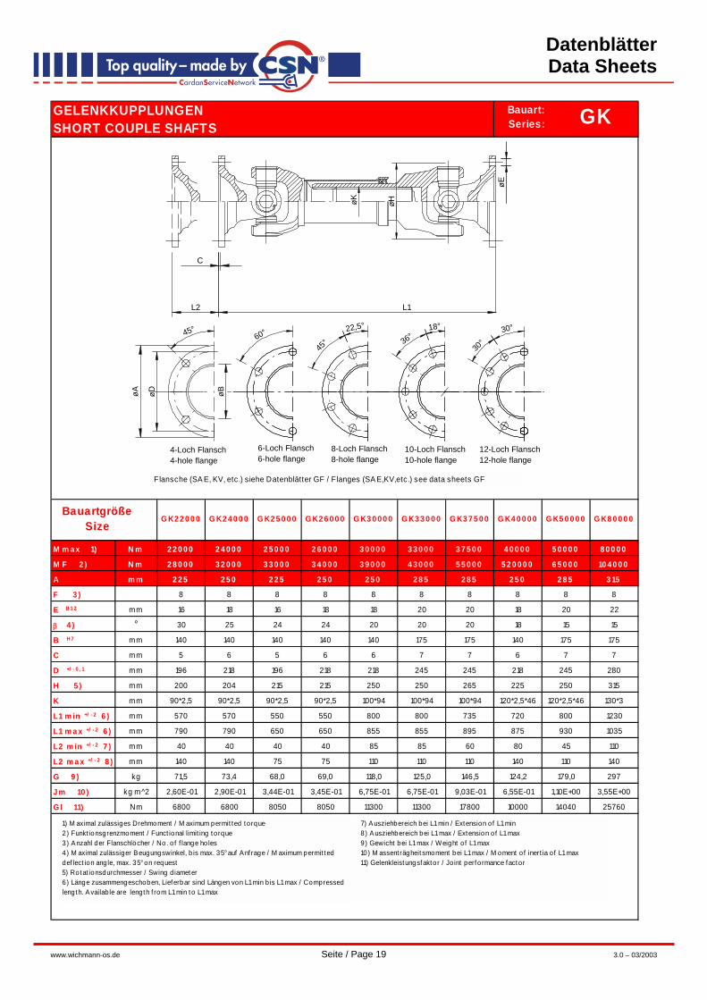
1) M aximal zulässiges Drehmoment / M aximum permit ted torque2) Funkt ionsgrenzmoment / Funct ional limit ing torque3) Anzahl der Flanschlöcher / No. o f f lange ho les4) M aximal zulässiger Beugungswinkel, b is max. 35° auf Anf rage / M aximum permit ted def lect ion ang le, max. 35° on request5) Rotat ionsdurchmesser / Swing d iameter6) Länge zusammengeschoben, Lieferbar sind Längen von L1 min b is L1 max / Compressed length. Availab le are length f rom L1 min to L1 max
7) Ausziehbereich bei L1 min / Extension of L1 min8) Ausziehbereich bei L1 max / Extension of L1 max9) Gewicht bei L1 max / Weight o f L1 max10) M assent rägheit smoment bei L1 max / M oment of inert ia of L1 max11) Gelenkleistungsfaktor / Jo int performance factor
Flansche (SA E, KV, etc.) s iehe Datenblätter GF / Flanges (SA E,KV,etc.) see data sheets GF
GKBauart:Series:
BaugrößeSize
L2
C
L1
4-Loch Flansch4-hole flange
6-Loch Flansch6-hole flange
8-Loch Flansch8-hole flange
10-Loch Flansch10-hole flange
12-Loch Flansch12-hole flange
øA øD øB
øK øH
45°60° 22,5°
45°
18°
36°30°
30°
øE

Datenblätter Data Sheets
www.wichmann-os.de Seite / Page 18 3.0 – 03/2003
GELENKKUPPLUNGENSHORT COUPLE SHAFTS
GK06300 GK07200 GK07700 GK08500 GK10000 GK11000 GK12500 GK13000 GK17200 GK20000
M max 1) N m 6300 7200 7700 8500 10000 11000 12500 13000 17200 20000
M F 2) N m 9000 10200 10500 10500 13000 15500 16900 17000 23000 26000
A mm 150 150/ 180 150 180 180 180 180 180 180/ 225 180
F 3) 8 8 8 8 8 8 8 10 10/8 10
E B12 mm 12 12/14 12 14 14 14 14 16 16 16
β 4) ° 30 25 20/35 25 20/35 25 25 35 15/25 30
B H7 mm 90 90/110 90 110 110 110 110 110 110/140 110
C mm 3 3 3 3 3 3 3 3 3/5 3
D +/ - 0, 1 mm 130 130/155,5 130 155,5 155,5 155,5 155,5 155,5 155,5/196 155,5
H 5) mm 138 148 156 158 156 159 172 168 178 200
K mm 55*2,5*20 60*2,5*22 65*2,5*24 62*1,75*35 65*2,5*24 65*2,5*24 68*1,75*37 75*2,5*28 78*2*38 90*2,5*34
L1 min +/ - 2 6 ) mm 490 400 480 430 400 460 450 525 435 570
L1 max +/ - 2 6 ) mm 578 578 615 525 615 650 560 660 700 790
L2 min +/ - 2 7 ) mm 40 50 40 55 50 50 40 40 30 40
L2 max +/ - 2 8 ) mm 110 110 110 110 110 110 110 110 110 140
G 9) kg 23,8 21,1 33,6 29,4 35,9 26,52 35,7 45,8 44,0 68,0
Jm 10) kg m^2 3,74E-02 4,11E-02 6,70E-02 7,76E-02 7,70E-02 4,68E-02 1,00E-01 1,03E-01 1,30E-01 2,13E-01
Gl 11) Nm 2300 2540 3100 2800 3100 3260 3500 4200 4600 6800
GKBauart:Series:
BaugrößeSize
L2
C
L1
4-Loch Flansch4-hole flange
6-Loch Flansch6-hole flange
8-Loch Flansch8-hole flange
10-Loch Flansch10-hole flange
12-Loch Flansch12-hole flange
øA øD øB
øK øH
45°60° 22,5°
45°
18°
36°30°
30°
øE
Flansche (SAE, KV, etc.) siehe Datenblätter GF / Flanges (SAE,KV,etc.) see data sheets GF
1) M aximal zulässiges Drehmoment / M aximum permitted torque2) Funktionsgrenzmoment / Functional limit ing torque3) Anzahl der Flanschlöcher / No. of f lange holes4) M aximal zulässiger Beugungswinkel, bis max. 35° auf Anfrage / M aximum permitted def lect ion angle, max. 35° on request5) Rotat ionsdurchmesser / Swing diameter6) Länge zusammengeschoben, Lieferbar sind Längen von L1 min bis L1 max / Compressed length. Available are length f rom L1 min to L1 max
7) Ausziehbereich bei L1 min / Extension of L1 min8) Ausziehbereich bei L1 max / Extension of L1 max9) Gewicht bei L1 max / Weight of L1 max10) M assenträgheitsmoment bei L1 max / M oment of inert ia of L1 max11) Gelenkleistungsfaktor / Joint performance factor
Datenblätter Data Sheets
www.wichmann-os.de Seite / Page 19 3.0 – 03/2003
GELENKKUPPLUNGENSHORT COUPLE SHAFTS
G K2 2 0 0 0 G K2 4 0 0 0 G K2 5 0 0 0 G K2 6 0 0 0 G K3 0 0 0 0 G K3 3 0 0 0 G K3 7 5 0 0 G K4 0 0 0 0 G K5 0 0 0 0 G K8 0 0 0 0
M m a x 1) N m 2 2 0 0 0 2 4 0 0 0 2 5 0 0 0 2 6 0 0 0 3 0 0 0 0 3 3 0 0 0 3 7 5 0 0 4 0 0 0 0 5 0 0 0 0 8 0 0 0 0
M F 2 ) N m 2 8 0 0 0 3 2 0 0 0 3 3 0 0 0 3 4 0 0 0 3 9 0 0 0 4 3 0 0 0 5 5 0 0 0 5 2 0 0 0 0 6 5 0 0 0 10 4 0 0 0
A m m 2 2 5 2 5 0 2 2 5 2 5 0 2 5 0 2 8 5 2 8 5 2 5 0 2 8 5 3 15
F 3 ) 8 8 8 8 8 8 8 8 8 8
E B 1 2 mm 16 18 16 18 18 20 20 18 20 22
β 4 ) ° 30 25 24 24 20 20 20 18 15 15
B H 7 mm 140 140 140 140 140 175 175 140 175 175
C mm 5 6 5 6 6 7 7 6 7 7
D +/ - 0 , 1 mm 196 218 196 218 218 245 245 218 245 280
H 5 ) mm 200 204 215 215 250 250 265 225 250 315
K mm 90*2,5 90*2,5 90*2,5 90*2,5 100*94 100*94 100*94 120*2,5*46 120*2,5*46 130*3
L1 m in +/ - 2 6 ) mm 570 570 550 550 800 800 735 720 800 1230
L1 m a x +/ - 2 6 ) mm 790 790 650 650 855 855 895 875 930 1035
L2 m in +/ - 2 7 ) mm 40 40 40 40 85 85 60 80 45 110
L2 m a x +/ - 2 8 ) mm 140 140 75 75 110 110 110 140 110 140
G 9 ) kg 71,5 73,4 68,0 69,0 118,0 125,0 146,5 124,2 179,0 297
J m 10 ) kg m^2 2,60E-01 2,90E-01 3,44E-01 3,45E-01 6,75E-01 6,75E-01 9,03E-01 6,55E-01 1,10E+00 3,55E+00
G l 11) Nm 6800 6800 8050 8050 11300 11300 17800 10000 14040 25760
BauartgrößeSize
GKBauart:Series:
L2
C
L1
4-Loch Flansch4-hole flange
6-Loch Flansch6-hole flange
8-Loch Flansch8-hole flange
10-Loch Flansch10-hole flange
12-Loch Flansch12-hole flange
øA øD øB
øK øH
45°60° 22,5°
45°
18°
36°30°
30°
øE
F lansche (SA E, KV, etc.) siehe Datenblätter GF / Flanges (SA E,KV,etc.) see data sheets GF
1) M aximal zulässiges Drehmoment / M aximum permit ted torque2) Funkt ionsgrenzmoment / Funct ional limit ing torque3) Anzahl der Flanschlöcher / No. of f lange ho les4) M aximal zulässiger Beugungswinkel, b is max. 35° auf Anf rage / M aximum permit ted def lect ion angle, max. 35° on request5) Rotat ionsdurchmesser / Swing d iameter6) Länge zusammengeschoben, Lieferbar sind Längen von L1 min b is L1 max / Compressed length. Available are length f rom L1 min to L1 max
7) Ausziehbereich bei L1 min / Extension of L1 min8) Ausziehbereich bei L1 max / Extension of L1 max9) Gewicht bei L1 max / Weight of L1 max10) M assent rägheit smoment bei L1 max / M oment o f inert ia of L1 max11) Gelenkleistungsfaktor / Jo int performance factor

Datenblätter Data Sheets
www.wichmann-os.de Seite / Page 20 3.0 – 03/2003
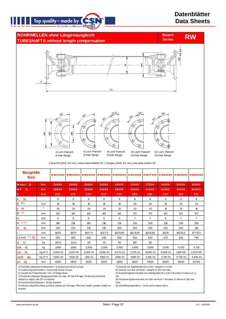
ROHRWELLEN ohne LängenausgleichTUBESHAFTS without length compensation
R W00160 R W00260 R W00500 R W01900 R W04900 R W04000 R W05000
M max 1) N m 160 260 500 1400 1900 3000 3500 4900 4400 5000
M F 2) N m 200 320 650 1850 3400 4000 4600 6500 5200 6200
A mm 58 65 75 90/ 100 120 120 150 150 120 150
F 3) 4 4 6 4/6 8 8 8 8 8 8
E B12 mm 5 6 6 8 8 8/10 12 12 10 12
β 4) ° 30 30 30 25/35 25 35 25 25 35 35
B H7 mm 30 35 42 47/57 75 75 90 90 75 90
C mm 1,5 1,7 2 2,5 2,5 2,5 3 3 2,5 3
D +/ - 0, 1 mm 47 52 62 74,5/84 101,5 101,5 130 130 101,5 130
H 5) mm 52 60 70 85 98 116 116 127 125 125
I mm 28*1,5 32*1,5 40*2 50*3 76,2*2,4 76,2*2,4 70*3 90*3 70*3 90*3 90*3 80*3,5 80*3,5
L1 min +/ - 2 6 ) mm 160 165 200 243 239 307 307 322 420 430
G 7) kg 0,9 1,2 1,9 5,0 5,8 9,8 10,4 9,8 11,7 14,0
GR 8) kg 0,100 0,110 0,190 0,348/0,440 0,440 0,500/0,644 0,500/0,644 0,644 0,660 0,660
Jm 9) kg m^2 1,52E-03 3,36E-04 7,80E-03 5,26E-02 5,26E-02 1,28E-01 1,28E-01 2,38E-01 1,80E-01 2,90E-01
JmR 10) kg m^2 1,70E-04 2,60E-04 6,80E-04 1,93E-03 5,90E-03 1,93E-03 5,70E-03
1,22E-035,70E-03 1,22E-03 1,22E-02 9,70E-03 9,70E-03
Gl 11) Nm 90 160 240 660 640 990 990 1100 1650 1650
R W01250 R W01253
R W03000 R W03002
R W03500 R W03502
Flansche (SAE, KV, etc.) siehe Datenblätter GF / Flanges (SAE, KV, etc.) see data sheets GF
RWBauart:Series:
BaugrößeSize
4-Loch Flansch4-hole flange
6-Loch Flansch6-hole flange
8-Loch Flansch8-hole flange
10-Loch Flansch10-hole flange
12-Loch Flansch12-hole flange
øA øD øB
45°60° 22,5°
45°
18°
36°30°
30°
øHøI
C
L1
øE
1) M aximal zulässiges Drehmoment / M aximum permitted torque2) Funktionsgrenzmoment / Functional limited torque3) Anzahl der Flanschlöcher / No. of f lange holes4) M aximal zulässiger Beugungswinkel, bis max. 35° auf Anfrage / M aximum permitted deflect ion angle, max 35° on request5) Rotat ionsdurchmesser / Swing diameter6) Kürzest mögliche Länge, größere Längen auf Anfrage / Shortest length, greater length on request
7) Gewicht der Gelenkwelle bei L1 min / Weight of L1 min8) Gewicht von 100 mm Rohr / Weight of 100 mm tube9) M assenträgheitsmoment der Gelenkwelle bei L1 min / M oment of inert ia of L1 min10) M assenträgheitsmoment von 100 mm Rohr / M oment of inert ia of 100 mm tube11) Gelenkleistungsfaktor / Joint performance factor

Datenblätter Data Sheets
www.wichmann-os.de Seite / Page 21 3.0 – 03/2003
ROHRWELLEN ohne LängenausgleichTUBESHAFTS without length compensation
R W06300 R W07200 R W07700 R W08500 R W10000 R W11000 R W12500 R W13000 R W17200 R W20000
M max 1) N m 6300 7200 7700 8500 10000 11000 12500 13000 17200 20000
M F 2) N m 8200 10200 10500 10500 13000 15500 16900 17000 23000 26000
A mm 150 150/ 180 150 180 180 180 225 180 180/ 225 180
F 3) 8 8 8 8 8 8 8 10 10/8 10
E B12 mm 12 12/14 12 14 14 14 14 16 16 16
β 4) ° 35 25 35 25 35 25/35 25 35 25 30
B H7 mm 90 90/110 90 110 110 110 110 110 110/140 110
C mm 3 3 3 3 3 3 3 3 3/5 3
D +/ - 0, 1 mm 130 130/155,5 130 155,5 155,5 155,5 155,5 155,5 155,5/196 155,5
H 5) mm 138 148 156 158 156 159 172 168 178 200
I mm 85*5 92*5 90*5,5 120*3 90*5,5 100*5 120*4 100*6 120*6 140*5
L1 min +/ - 2 6 ) mm 390 350 420 420 420 445 425 460 475 490
G 7) kg 16,3 17,98 19,5 22,8 24,0 27,5 28 28 33,1 46,01
GR 8) kg 0,986 1,070 1,146 0,866 1,146 1,170 1,140 1,390 1,690 1,670
Jm 9) kg m^2 3,53E-02 7,50E-02 5,40E-02 6,60E-02 6,50E-02 9,80E-02 9,54E-01 8,80E-02 1,18E-01 1,63E-01
JmR 10) kg m^2 1,58E-02 2,00E-02 2,51E-02 2,96E-02 2,51E-02 2,70E-02 3,85E-02 3,09E-02 5,50E-02 7,60E-02
Gl 11) Nm 2300 2540 3100 2800 3100 3260 3500 4200 4600 6800
RWBauart:Series:
BaugrößeSize
4-Loch Flansch4-hole flange
6-Loch Flansch6-hole flange
8-Loch Flansch8-hole flange
10-Loch Flansch10-hole flange
12-Loch Flansch12-hole flange
øA øD øB
45°60° 22,5°
45°
18°
36°30°
30°
øHøI
C
L1
øE
Flansche (SAE, KV, etc.) siehe Datenblätter GF / Flanges (SAE, KV, etc.) see data sheets GF
1) M aximal zulässiges Drehmoment / M aximum permit ted torque2) Funktionsgrenzmoment / Funct ional limited torque3) Anzahl der Flanschlöcher / No. of f lange holes4) M aximal zulässiger Beugungswinkel, bis max. 35° auf Anfrage / M aximum permitted deflect ion angle, max 35° on request5) Rotat ionsdurchmesser / Swing diameter6) Kürzest mögliche Länge, größere Längen auf Anfrage / Shortest length, greater length on request
7) Gewicht der Gelenkwelle bei L1 min / Weight of L1 min8) Gewicht von 100 mm Rohr / Weight of 100 mm tube9) M assenträgheitsmoment der Gelenkwelle bei L1 min / M oment of inert ia of L1 min10) M assenträgheitsmoment von 100 mm Rohr / M oment of inert ia of 100 mm tube11) Gelenkleistungsfaktor / Joint performance factor
Datenblätter Data Sheets
www.wichmann-os.de Seite / Page 22 3.0 – 03/2003
ROHRWELLEN ohne LängenausgleichTUBESHAFTS without length compensation
R W22000 R W24000 R W25000 R W26000 R W30000 R W33000 R W37500 R W40000 R W50000 R W80000
M max 1) N m 22000 24000 25000 26000 30000 33000 37500 40000 50000 80000
M F 2) N m 28000 32000 33000 34000 39000 43000 55000 52000 65000 104000
A mm 225 250 225 250 250 285 285 250 285 315
F 3) 8 8 8 8 8 8 8 8 8 8
E B12 mm 16 18 16 18 18 20 20 18 20 22
β 4) ° 30 25 24 24 20 20 20 18 15 15
B H7 mm 140 140 140 140 140 175 175 140 175 175
C mm 5 6 5 6 6 7 7 6 7 7
D +/ - 0, 1 mm 196 218 196 218 218 245 245 218 245 280
H 5) mm 200 204 215 215 250 250 265 225 250 315
I mm 140*5 140*5 143*7,5 143*7,5 162*9,85 162*9,85 162*9,85 160*8 165*12,5 177*17,5
L1 min +/ - 2 6 ) mm 550 550 540 540 650 650 640 570 625 790
G 7) kg 49,51 51,41 58 59 95 105 112 - - -
GR 8) kg 1,665 1,665 2,506 2,506 3,400 3,400 3,690 3,000 4,700 6,710
Jm 9) kg m^2 2,02E-01 2,02E-01 3,05E-01 3,06E-01 6,57E-01 7,37E-01 9,03E-01 6,55E-01 1,10E+00 2,97E+00
JmR 10) kg m^2 7,60E-02 7,60E-02 1,15E-01 1,15E-01 1,99E-01 1,99E-01 2,15E-01 1,74E-01 2,75E-01 4,43E-01
Gl 11) Nm 6800 6800 8050 8050 11300 11300 17800 10000 14040 25760
RWBauart:Series:
BaugrößeSize
4-Loch Flansch4-hole flange
6-Loch Flansch6-hole flange
8-Loch Flansch8-hole flange
10-Loch Flansch10-hole flange
12-Loch Flansch12-hole flange
øA øD øB
45°60° 22,5°
45°
18°
36°30°
30°
øHøI
C
L1
øE
1) M aximal zulässiges Drehmoment / M aximum permit ted torque2) Funktionsgrenzmoment / Functional limited torque3) Anzahl der Flanschlöcher / No. of f lange holes4) M aximal zulässiger Beugungswinkel, bis max. 35° auf Anfrage / M aximum permit ted deflect ion angle, max 35° on request5) Rotat ionsdurchmesser / Swing diameter6) Kürzest mögliche Länge, größere Längen auf Anfrage / Shortest length, greater length onrequest
7) Gewicht der Gelenkwelle bei L1 min / Weight of L1 min8) Gewicht von 100 mm Rohr / Weight of 100 mm tube9) M assenträgheitsmoment der Gelenkwelle bei L1 min / M oment of inert ia of L1 min10) M assenträgheitsmoment von 100 mm Rohr / M oment of inert ia of 100 mm tube11) Gelenkleistungsfaktor / Joint performance factor
Flansche (SAE, KV, etc.) siehe Datenblätter GF / Flanges (SAE, KV, etc.) see data sheets GF

Datenblätter Data Sheets
www.wichmann-os.de Seite / Page 23 3.0 – 03/2003
ZWISCHENWELLENINTERMEDIATE SHAFTS
Z W01250 Z W03000 Z W04000 Z W05000 Z W06300 Z W07700 Z W10000 Z W13000 Z W17000
M max 1) N m 1400 3000 4000 5000 6300 7700 10000 13000 17000
M F 2) N m 1850 4000 5200 6500 8200 10500 13000 17000 22500
A mm 100 120 120 150 150 150 180 180 180
F 3) 6 8 8 8 8 8 8 8 10
E B12 mm 8 10 10 12 12 12 14 14 16
β 4) ° 35 35 35 35 35 35 35 35 30
B H7 mm 57 75 75 90 90 90 110 110 110
B 1 h6 mm 57 75 75 90 90 90 110 110 110
C +0, 2 mm 2,5 2,5 2,5 3 3 3 3 3 3
C 1 - 0, 2 mm 2,2 2,2 2,2 2,8 2,8 2,8 2,8 2,8 2,8
D mm 84 101,5 101,5 130 130 130 155,5 155,5 155,5
H 5) mm 100 116 125 125 138 156 156 168 178
I mm 50*3 70*3 80*3,5 80*3,5 85*5 90*5,5 90*5,5 100*6 111,5*6,75
K mm 93 99 107 107 124,5 124,5 140 140 156
L1 +/ - 2 6) mm 237 285 335 335 365 376 381 415 415
M mm 132,5 150,0 164,3 164,3 187,5 187,5 200 200 208,5
M 1 mm 119,5 126,5 135 135 164,5 164,5 180,000 180,000 196,500
N mm 14 14 14 14 18 18 18 18 22
O mm 47,60 49,20 54,00 54,00 63,50 63,50 69,90 69,90 79,40
P mm 19 19 19 19 22,5 22,5 25 25 27,5
Q mm 35 45 45 45 55 55 60 60 70
R mm 45 48 48 48 60 60 60 60 65
S mm 78,8 91,4 91,4 86,4 104,8 104,8 113 113 118,5
W mm 163 179 192 192 222 222 240 240 260
G 7) kg 4,57 9 10,1 11,77 13,45 15,38 20,77 23,375 22,85
GR 8) kg 0,348 0,5 0,66 0,66 0,986 1,146 1,146 1,391 1,74
Gl 9) Nm 660 990 1650 1650 2300 3100 3100 4200 4600
ZWBauart:Series:
BaugrößeSize
H I
E
A
D
B
B1
D
A
E R
L1
S C1
N
Q
O
P
K
M1
M
W
C
1) M aximal zulässiges Drehmoment / M aximum permitted torque2) Funktionsgrenzmoment / Functional limited torque3) Anzahl der Flanschlöcher / No. of f lange holes4) M aximal zulässiger Beugungswinkel, bis max. 35° auf Anfrage / M aximum permitted deflect ion angle, max 35° on request5) Rotat ionsdurchmesser / Swing diameter6) Kürzest mögliche Länge, größere Längen auf Anfrage / Shortest length, greater length on request7) Gewicht der Gelenkwelle bei L1 min, ohne Lager / Weight of L1 min, without bearing8) Gewicht von 100 mm Rohr / Weight of 100 mm tube9) Gelenkleistungsfaktor / Joint performance factor

Datenblätter Data Sheets
www.wichmann-os.de Seite / Page 24 3.0 – 03/2003
ZWISCHENWELLEN SonderausführungINTERMEDIATE SHAFTS Special design
Z W01200 Z W01200 Z W01202 Z W01203 Z W01204
/ 6 / 9 / 9 / 9 / 9
M max 1) N m 1200 1200 1200 1200 1200
A mm 90 100 90/ 100 90/ 100 90/ 100
F 2) 4 6 4/6 4/6 4/6
E B12 mm 8 8 8 8 8
β 3) ° 22 22 22 22 22
B H7 mm 47 57 47/57 47/57 47/57
B 1 h6 mm 47 57 47/57 47/57 47/57
C +0, 2 mm 2,5 2,5 2,5 2,5 2,5
C 1 - 0, 2 mm 2,2 2,2 2,5 2,5 2,5
D +/ - 0, 1 mm 74,5 84 74,5/84 74,5/84 74,5/84
H 4) mm 100 100 100 100 100
I mm 50,8*2,41 50,8*2,41 70*2 76,2*2,41 80*2
K mm 30 30 30 30 30
L1 min +/ - 2 5 ) mm 250 250 250 250 250
G 6) kg 4 4,1 4,2 4,4 4,4
GR 7) kg 0,288 0,288 0,335 0,440 0,385
ZWBauart:Series:
1) M aximal zulässiges Drehmoment / M aximum permitted torque2) Anzahl der Flanschlöcher / No. of f lange holes3) M aximal zulässiger Beugungswinkel, bis max. 35° auf Anfrage / M aximum permit ted def lect ion angle, max 35° on request4) Rotat ionsdurchmesser / Swing diameter
5) Kürzest mögliche Länge, größere Längen auf Anfrage / Shortest length, greater length on request6) Gewicht der Gelenkwelle bei L1 min, ohne Lager / Weight of L1 min, without bearing7) Gewicht von 100 mm Rohr / Weight of 100 mm tube
BaugrößeSize
Einsatzgebiet z.B. schnellaufende, präzise Nebenantriebe.Application e.g. fast running, precision power take offs.
Lieferumfang ohne StehlagerExtent of delivery without intermediate bearing
A
C1
D
B1
K I DB A
E
L1
C
H
Datenblätter Data Sheets
www.wichmann-os.de Seite / Page 25 3.0 – 03/2003
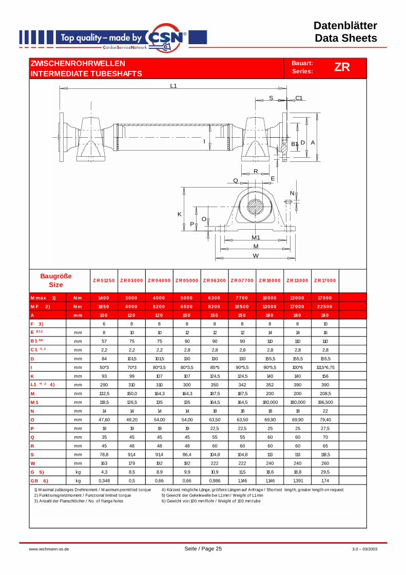
ZWISCHENROHRWELLENINTERMEDIATE TUBESHAFTS
Z R 01250 Z R 03000 Z R 04000 Z R 05000 Z R 06300 Z R 07700 Z R 10000 Z R 13000 Z R 17000
M max 1) N m 1400 3000 4000 5000 6300 7700 10000 13000 17000
M F 2) N m 1850 4000 5200 6500 8200 10500 13000 17000 22500
A mm 100 120 120 150 150 150 180 180 180
F 3) 6 8 8 8 8 8 8 8 10
E B12 mm 8 10 10 12 12 12 14 14 16
B 1 h6 mm 57 75 75 90 90 90 110 110 110
C 1 - 0, 2 mm 2,2 2,2 2,2 2,8 2,8 2,8 2,8 2,8 2,8
D mm 84 101,5 101,5 130 130 130 155,5 155,5 155,5
I mm 50*3 70*3 80*3,5 80*3,5 85*5 90*5,5 90*5,5 100*6 111,5*6,75
K mm 93 99 107 107 124,5 124,5 140 140 156
L1 +/ - 2 4) mm 290 310 310 300 350 342 352 390 390
M mm 132,5 150,0 164,3 164,3 187,5 187,5 200 200 208,5
M 1 mm 119,5 126,5 135 135 164,5 164,5 180,000 180,000 196,500
N mm 14 14 14 14 18 18 18 18 22
O mm 47,60 49,20 54,00 54,00 63,50 63,50 69,90 69,90 79,40
P mm 19 19 19 19 22,5 22,5 25 25 27,5
Q mm 35 45 45 45 55 55 60 60 70
R mm 45 48 48 48 60 60 60 60 65
S mm 78,8 91,4 91,4 86,4 104,8 104,8 113 113 118,5
W mm 163 179 192 192 222 222 240 240 260
G 5) kg 4,3 8,5 8,9 9,9 10,9 11,5 18,6 18,8 29,5
GR 6) kg 0,348 0,5 0,66 0,66 0,986 1,146 1,146 1,391 1,74
ZRBauart:Series:
BaugrößeSize
I B1 D A
ER
S C1
N
Q
OP
K
M1MW
L1
1) M aximal zulässiges Drehmoment / M aximum permit ted torque2) Funkt ionsgrenzmoment / Funct ional limited torque3) Anzahl der Flanschlöcher / No. of f lange holes
4) Kürzest mögliche Länge, größere Längen auf Anfrage / Shortest length, greater length on request5) Gewicht der Gelenkwelle bei L1 min / Weight of L1 min6) Gewicht von 100 mm Rohr / Weight of 100 mm tube

Datenblätter Data Sheets
www.wichmann-os.de Seite / Page 26 3.0 – 03/2003
ZWISCHENROHRWELLEN SonderausführungenINTERMEDIATE TUBESHAFTS Special design
Z R 0 12 0 0 Z R 0 12 0 0 Z R 0 12 0 2 Z R 0 12 0 2 Z R 0 12 0 3 Z R 0 12 0 3 Z R 0 12 0 4 Z R 0 12 0 4 Z WL0 7 7 0 0 Z WL10 0 0 0
/ 6 / 9 / 6 / 9 / 6 / 9 / 6 / 9 / 15 / 2 5
M m a x 1) N m 12 0 0 12 0 0 12 0 0 12 0 0 12 0 0 12 0 0 12 0 0 12 0 0 7 7 0 0 10 0 0 0
A m m 9 0 10 0 9 0 10 0 9 0 10 0 9 0 10 0 15 0 18 0
F 2 ) 4 6 4 6 4 6 4 6 8 8
E B 1 2 mm 8 8 8 8 8 8 8 8 12 14
B 1 h6 mm 47 57 47 57 47 57 47 57 90 110
C 1 +/ - 0 , 1 mm 2,2 2,2 2,2 2,2 2,2 2,2 2,2 2,2 2,8 2,8
D mm 74,5 84 74,5 84 74,5 84 74,5 84 130 155
H mm 170 170
H 1 mm 77,5 77,5
H 2 mm 30 30
I mm 50,8*2,41 50,8*2,41 70*2 70*2 76,2*2,41 76,2*2,41 80*2 80*2
K mm 30 30 30 30 30 30 30 30 23,5 23,5
L1 +/ - 2 3 ) mm 250 250 250 250 250 250 250 250 315 315
L2 mm 145 145
L3 mm 55 55
L4 mm 115 115
M 1 mm 265 265
M 2 mm 205 205
G 4 ) kg 4,1 4,5 4,3 4,7 4,4 4,8 4,5 4,9 42,9 44,2
G R 5 ) kg 0,228 0,228 0,335 0,335 0,440 0,440 0,385 0,385
ZRBauart:Series:
BaugrößeSize
Einsatzgebiet z.B. schnellaufende, präzise Nebenantriebe.Application e.g. fast running, precision power take offs.
Lieferumfang ohne StehlagerExtent of delivery without intermediate bearing
A
H
H1
H2
L3 L4
L2
L1
D
B1
M1
M2
E C1
E
A
D
B1
C1
K I
K
L1
1) M aximal zulässiges Drehmoment / M aximum permit ted torque2) Anzahl der Flanschlöcher / No. of f lange holes3) Kürzest mögliche Länge, größere Längen auf Anf rage / Shortest length, greater length on request
4) Gewicht der Gelenkwelle bei L1 min / Weight o f L1 min5) Gewicht von 100 mm Rohr / Weight of 100 mm tube

Datenblätter Data Sheets
www.wichmann-os.de Seite / Page 27 3.0 – 03/2003
FLANSCHGELENKEFLANGE JOINTS
F G00160 F G00260 F G00500 F G01250 F G01900 F G03000 F G03500 F G04900 F G04000 F G05000
M max 1) N m 190 320 650 1400 1900 3000 3500 4900 4000 5000
M F 2) N m 250 350 850 1850 3400 4200 4600 6500 5200 6500
A mm 58 65 75 90/ 100 120 120 150 150 120 150
F 3) 4 4 6 4/6 8 8 8 8 8 8
E B12 mm 5 6 6 8 8 8/10 12 12 10 12
β 4) ° 30 30 30 25/35 25 35 18 25 35 35
B H7 mm 30 35 42 47/57 75 75 90 90 75 90
C mm 1,5 1,7 2,2 2,5 2,5 2,5 3 3 2,5 3
D +/ - 0, 1 mm 47 52 62 74,5/84 101,5 101,5 130 130 101,5 130
H 5) mm 52 60 70 100 98 116 116 127 125 125
L1 min +/ - 2 6 ) mm 60 64 72 96/116 108 140 112 146 150 160
G 7) kg 0,4 0,56 0,8 2,13 2,2 4,15 4,75 4,8 5 6,7
Jm 8) kg m^2 7,00E-05 1,50E-04 3,10E-04 2,92E-03 8,90E-03 6,50E-03 6,70E-03 2,45E-03 8,10E-03 1,43E-02
Gl 9) Nm 90 160 240 660 640 990 990 1100 1650 1650
FGBauart:Series:
BaugrößeSize
øH øB øD øA
øE
C
L1
4-Loch Flansch4-hole flange
6-Loch Flansch6-hole flange
8-Loch Flansch8-hole flange
10-Loch Flansch10-hole flange
12-Loch Flansch12-hole flange
45 60 22,5
45
1836
30
30
øA øD øB
Flansche (SAE, KV, etc.) siehe Datenblätter GF / Flanges (SAE, KV, etc.) see data sheets GF
1) M aximal zulässiges Drehmoment / M aximum permit ted torque2) Funkt ionsgrenzmoment / Funct ional limited torque3) Anzahl der Flanschlöcher / No. of f lange holes4) M aximal zulässiger Beugungswinkel, bis max. 35° auf Anfrage / M aximum permit ted deflect ion angle, max 35° on request5) Rotat ionsdurchmesser / Swing diameter
6) Länge, abhängig vom Beugungswinkel / Length, depending on deflect ion angle7) Gewicht / Weight 8) M assenträgheitsmoment / M oment of inert ia9) Gelenkleistungsfaktor / Joint performance factor

Datenblätter Data Sheets
www.wichmann-os.de Seite / Page 28 3.0 – 03/2003
FLANSCHGELENKEFLANGE JOINTS
F G06300 F G07200 F G07700 F G08500 F G10000 F G11000 F G12500 F G13000 F G17200 F G20000
M max 1) N m 6300 7200 7700 8500 10000 11000 12500 13000 17200 20000
M F 2) N m 8200 10200 10500 10500 13000 15500 16900 17000 23000 26000
A mm 150 150/ 180 150 180 180 180 180 180 180/ 225 180
F 3) 8 8 8 8 8 8 8 10 10/8 10
E B12 mm 12 12/14 12 14 14 14 14 16 16 16
β 4) ° 30 25 35 25 25 25/35 25 35 25 30
B H7 mm 90 90/110 90 110 110 110 110 110 110/140 110
C mm 3 3 3 3 3 3 3 3 3/5 3
D +/ - 0, 1 mm 130 130/15,5 130 15,5 15,5 155,5 155,5 155,5 155,5/196 155,5
H 5) mm 138 148 156 158 156 159 172 168 178 200
L1 min +/ - 2 6 ) mm 164 150 190 184 190 180 200 200 190 220
G 7) kg 9 10,9 11,4 11,1 13,5 13,9 14,0 14,2 17 20,5
Jm 8) kg m^2 2,11E-02 2,50E-02 2,82E-02 7,76E-02 4,93E-02 5,65E-02 1,00E-01 6,57E-02 7,81E-02 8,93E-02
Gl 9) Nm 2300 2540 3100 2400 3100 3260 3500 4200 4600 6800
FGBauart:Series:
BaugrößeSize
øH øB øD øA
øE
C
L1
4-Loch Flansch4-hole flange
6-Loch Flansch6-hole flange
8-Loch Flansch8-hole flange
10-Loch Flansch10-hole flange
12-Loch Flansch12-hole flange
45 60 22,5
45
1836
30
30
øA øD øB
Flansche (SAE, KV, etc.) siehe Datenblätter GF / Flanges (SAE, KV, etc.) see data sheets GF
1) M aximal zulässiges Drehmoment / M aximum permitted torque2) Funkt ionsgrenzmoment / Functional limited torque3) Anzahl der Flanschlöcher / No. of f lange holes4) M aximal zulässiger Beugungswinkel, bis max. 35° auf Anfrage / M aximum permitted deflect ion angle, max 35° on request5) Rotat ionsdurchmesser / Swing diameter
6) Länge, abhängig vom Beugungswinkel / Length, depending on deflect ion angle7) Gewicht / Weight 8) M assenträgheitsmoment / M oment of inert ia9) Gelenkleistungsfaktor / Joint performance factor

Datenblätter Data Sheets
www.wichmann-os.de Seite / Page 29 3.0 – 03/2003
FLANSCHGELENKEFLANGE JOINTS
F G22000 F G24000 F G25000 F G26000 F G30000 F G33000 F G37500 F G40000 F G50000 F G80000
M max 1) N m 22000 24000 25000 26000 30000 33000 37500 40000 50000 80000
M F 2) N m 28000 32000 33000 34000 39000 43000 55000 52000 65000 104000
A mm 225 250 225 250 250 285 285 250 285 315
F 3) 8 8 8 8 8 8 8 8 8 8
E B12 mm 16 18 16 18 18 20 20 18 20 22
β 4) ° 30 25 24 24 20 20 20 18 15 15
B H7 mm 140 140 140 140 140 175 175 140 175 175
C mm 5 6 5 6 6 7 7 6 7 7
D +/ - 0, 1 mm 196 218 196 218 218 245 245 218 245 280
H 5) mm 200 204 215 215 250 250 265 225 250 315
L1 min +/ - 2 6 ) mm 220 220 216 216 260 260 270 250 260 360
G 7) kg 24 23,4 28 29,5 45,5 46,2 57,1 44,3 59,5 111,0
Jm 8) kg m^2 1,24E+00 1,21E+00 1,56E+00 1,60E+00 2,69E-01 3,59E-01 4,55E-01 2,75E+05 4,47E+05 7,91E+05
Gl 9) Nm 6800 6800 8050 8050 11300 11300 17800 10000 14040 25760
FGBauart:Series:
BaugrößeSize
øH øB øD øA
øE
C
L1
4-Loch Flansch4-hole flange
6-Loch Flansch6-hole flange
8-Loch Flansch8-hole flange
10-Loch Flansch10-hole flange
12-Loch Flansch12-hole flange
45 60 22,5
45
1836
30
30
øA øD øB
Flansche (SAE, KV, etc.) siehe Datenblätter GF / Flanges (SAE, KV, etc.) see data sheets GF
1) M aximal zulässiges Drehmoment / M aximum permitted torque2) Funkt ionsgrenzmoment / Functional limited torque3) Anzahl der Flanschlöcher / No. of f lange holes4) M aximal zulässiger Beugungswinkel, bis max. 35° auf Anfrage / M aximum permitted deflect ion angle, max 35° on request5) Rotat ionsdurchmesser / Swing diameter
6) Länge, abhängig vom Beugungswinkel / Length, depending on def lect ion angle7) Gewicht / Weight 8) M assenträgheitsmoment / M oment of inert ia9) Gelenkleistungsfaktor / Joint performance factor
Datenblätter Data Sheets
www.wichmann-os.de Seite / Page 30 3.0 – 03/2003
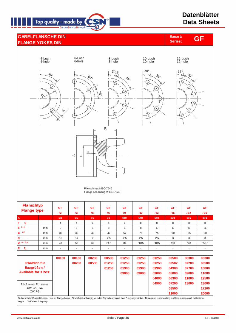
GABELFLANSCHE DIN FLANGE YOKES DIN
GF GF GF GF GF GF GF GF GF GF
/ 2 / 3 / 5 / 6 / 9 / 12 / 13 / 16 / 22 / 25
A 58 65 75 90 100 120 120 150 165 180
F 1) 4 4 6 4 6 8 8 8 8 8
E B12 mm 5 6 6 8 8 8 10 12 16 14
B H7 mm 30 35 42 47 57 75 75 90 95 110
C mm 1,5 1,7 2 2,5 2,5 2,5 2,5 3 3 3
D +/ - 0 , 1 mm 47 52 62 74,5 84 101,5 101,5 130 140 155,5
R 2) mm - - - - - - - - - -
00160 00160 00260 00500 01250 01250 01250 03500 06300 0630000260 00500 01250 01253 01253 01253 03502 07200 08500
01253 01900 01900 01900 04900 07700 1000003000 03000 03000 05000 09000 11000
04000 06300 11000 1250004900 07200 13000 13000
08500 1720011000 20000
Erhältlich für Baugrößen /
Available for sizes:
Für Bauart / For series:GW, GK, RW,
ZW, FG
1) Anzahl der Flanschlöcher / No. of f lange holes 2) M aß ist abhängig von der Flanschform und dem Beugungswinkel / Dimension is depending on f lange shape and def lect ion angle 3) Keilnut / Keyway
FlanschtypFlange type
GFBauart:Series:
R
C
BA
E
D
45° 60°
30°
22,5°45°
18°36°
15°30°
4-Loch4-hole
6-Loch6-hole
8-Loch8-hole
10-Loch10-hole
12-Loch12-hole
Flansch nach ISO 7646Flange according to ISO 7646

Datenblätter Data Sheets
www.wichmann-os.de Seite / Page 31 3.0 – 03/2003
GABELFLANSCHE DINFLANGE YOKES DIN
GF GF GF GF GF GF GF GF GF GF GF
/ 26 / 27 / 28 / 28KN / 29 / 30 / 30KN / 32 / 32KN / 101 / 101KN
A 180 180 225 225 225 250 250 285 285 315 315
F 1) 8 10 8 8 12 8 8 8 8 8 8
E B12 mm 16 16 16 17 17 18 19 20 21 22 23
B H7 mm 110 110 140 140 140 140 140 175 175 280 280
C mm 3 3 5 5 5 6 6 7 7 7 8
D +/ - 0, 1 mm 155,5 155,5 196 196 196 218 218 245 245 280 280
R 2) mm - - - - - - - - - - -
M x N 3) mm - - - 32x9 - - 40x12 - 40x15 40x15
08500 08500 13000 13000 13000 24000 24000 33000 33000 80000 8000010000 10000 17200 17200 17200 26000 26000 37500 3750011000 11000 22000 22000 22000 40000 40000 40000 4000012500 12500 25000 25000 25000 50000 50000 50000 5000013000 13000 40000 40000 40000 80000 8000017200 1720020000 20000
GFBauart:Series:
FlanschtypFlange type
Erhältlich für Baugrößen /
Available for sizes:
Für Bauart / For series:GW, GK, RW,
ZW, FG
R
C
BA
E
D
45° 60°
30°
22,5°45°
18°36°
15°30°
4-Loch4-hole
6-Loch6-hole
8-Loch8-hole
10-Loch10-hole
12-Loch12-hole
M
22,5°45°
E
8-hole- with keyway8-Loch- mit Keilnut
A B
C
R
N
Flansch nach ISO 7646Flange according to ISO 7646
1) Anzahl der Flanschlöcher / No. of f lange holes 2) M aß ist abhängig von der Flanschform und dem Beugungswinkel / Dimension is depending on f lange shape and def lect ion angle 3) Keilnut / Keyway

Datenblätter Data Sheets
www.wichmann-os.de Seite / Page 32 3.0 – 03/2003
GABELFLANSCHE KVFLANGE YOKES CS
GF GF GF GF GF GF
/ 38 / 33 / 34 / 35 / 36 / 37
A mm 100 122 150 165 180 200
F 1) 4 4 4 4 4 4
E B12 mm 8,5 11 13 13 15 15
D +/ - 0, 1 mm 84 100 130 140 150 165
R 2) mm 58 - - 97 - 108
01250 01250 05000 09000 08500 2500001253 01253 06300 11000 10000
01900 07200 1100003000 07700 1250004000 08500 1300004900 11000 1720006300 12500 20000
13000
Für Bauart / For series:GW, GK, RW,
ZW, FG
Erhältlich für Baugrößen / Available for
sizes:
Bauart:Series:
Für Bauart / For series:GW, GK, RW,
ZW, FG
Erhältlich für Baugrößen /
Available for sizes:
FlanschtypFlange type
GFBauart:Series:
Flansch nach ISO 8667Flange according to ISO 8667
1) Anzahl der Flanschlöcher / No. of f lange holes 2) M aß ist abhängig von der Flanschform und dem Beugungswinkel / Dimension is depending on f lange shape and def lect ion angle
Datenblätter Data Sheets
www.wichmann-os.de Seite / Page 33 3.0 – 03/2003
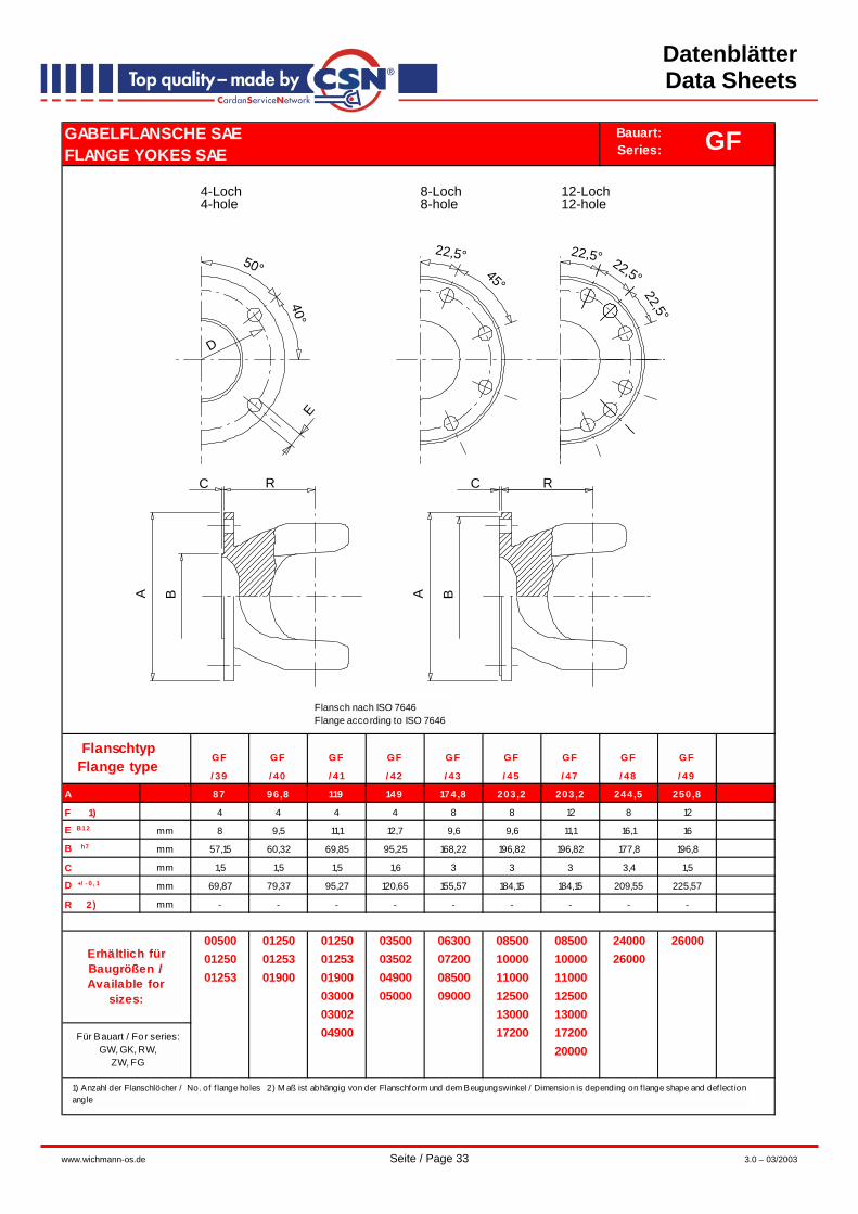
GABELFLANSCHE SAE FLANGE YOKES SAE
GF GF GF GF GF GF GF GF GF
/ 39 / 40 / 41 / 42 / 43 / 45 / 47 / 48 / 49
A 87 96,8 119 149 174,8 203,2 203,2 244,5 250,8
F 1) 4 4 4 4 8 8 12 8 12
E B12 mm 8 9,5 11,1 12,7 9,6 9,6 11,1 16,1 16
B h7 mm 57,15 60,32 69,85 95,25 168,22 196,82 196,82 177,8 196,8
C mm 1,5 1,5 1,5 1,6 3 3 3 3,4 1,5
D +/ - 0, 1 mm 69,87 79,37 95,27 120,65 155,57 184,15 184,15 209,55 225,57
R 2) mm - - - - - - - - -
00500 01250 01250 03500 06300 08500 08500 24000 2600001250 01253 01253 03502 07200 10000 10000 2600001253 01900 01900 04900 08500 11000 11000
03000 05000 09000 12500 1250003002 13000 1300004900 17200 17200
20000Für Bauart / For series:
GW, GK, RW,ZW, FG
Erhältlich für Baugrößen / Available for
sizes:
FlanschtypFlange type
GFBauart:Series:
R
BA
R
BA
C
E
40°
50°22,5°
45°
22,5° 22,5°
22,5°
C
D
4-Loch4-hole
8-Loch8-hole
12-Loch12-hole
Flansch nach ISO 7646Flange according to ISO 7646
1) Anzahl der Flanschlöcher / No. of f lange holes 2) M aß ist abhängig von der Flanschform und dem Beugungswinkel / Dimension is depending on f lange shape and def lect ion angle

Datenblätter Data Sheets
www.wichmann-os.de Seite / Page 34 3.0 – 03/2003
ANSCHLUSSFLANSCHE DINCOMPANION FLANGES DIN
A F 00150 A F 00250 A F 00400 A F 00750 A F 01250 A F 02500 A F 03000 A F 03500 A F 06300 A F 10000
/ 2 / 3 / 5 / 6 / 9 / 12 / 13 / 16 / 22 / 25
A mm 58 65 75 90 100 120 120 150 165 180
F 1) 4 4 6 4 6 8 8 8 8 8
E B12 mm 5 6 6 8 8 8 10 12 16 14
B h7 mm 30 35 42 47 57 75 75 90 95 110
C - 0, 2 mm 1,5 1,7 2 2,5 2,5 2,5 2,5 3 3 3
D +/ - 0, 1 mm 47 52 62 74,5 84 101,5 101,5 130 140 155,5
G P9 mm 6 8 8 10 12 14 16 18 20 22
H H7 mm 20 25 30 35 40 45 55 65 70 80
I mm 32 40 45 52 60 80 80 95 105 118
J M 5 M 6 M 6 M 6 M 8 M 8 M 8 M 10 M 10 M 12
K mm 38,5 43 51 60 70 88 84 110,5 115 131
L mm 30 40 48 55 62 70 85 115 120 125
M mm 4 5 6 8 8 9 10 12 12 14
N mm 22,8 28,3 33,3 38,3 43,3 48,8 59,3 69,4 74,9 85,4
00160 00160 00260 00500 01250 01250 01250 03500 06300 0630000260 00500 01250 01253 01253 01253 04900 07200 08500
01253 01900 01900 01900 05000 07700 1000003000 03000 03000 06300 09000 1100003002 03002 03002 07200 11000 12500
04000 08500 13000 1300004900 11000 17200
Erhältlich für Baugrößen /
Available for sizes:
Für Bauart / For series:GW, GK, RW,
ZW, FG
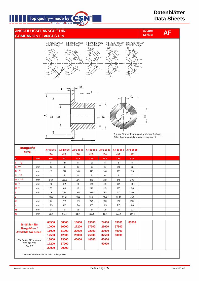
1) Anzahl der Flanschlöcher / No. of f lange holes
BaugrößeSize
AFBauart:Series:
Andere Flanschformen und M aße auf Anfrage.Other flanges and dimensions on request.L
M
45° 60°
30°
22,5°45°
18° 36°15° 30°
ø E
C
A I K H
G
BD N
J
4-Loch Flansch4-hole flange
6-Loch Flansch6-hole flange
8-Loch Flansch8-hole flange
10-Loch Flansch10-hole flange
12-Loch Flansch12-hole flange
Datenblätter Data Sheets
www.wichmann-os.de Seite / Page 35 3.0 – 03/2003
ANSCHLUSSFLANSCHE DINCOMPANION FLANGES DIN
A F 13000 A F 17000 A F 24000 A F 22000 A F 26000 A F 33000 A F 80000
/ 26 / 27 / 28 / 29 / 30 / 32 / 101
A mm 180 180 225 225 250 285 315
F 1) 8 10 8 12 8 8 8
E B12 mm 16 16 16 16 18 20 22
B h7 mm 110 110 140 140 140 175 175
C - 0, 2 mm 3 3 5 5 6 7 7
D +/ - 0, 1 mm 155,5 155,5 196 196 218 245 280
G P9 mm 22 22 28 28 28 32 32
H H7 mm 80 80 110 110 110 120 120
I mm 118 118 165 165 188 210 210
J M 12 M 12 M 16 M 16 M 16 M 18 M 20
K mm 131 131 171 171 190 214 214
L mm 125 125 170 170 195 210 180
M mm 14 14 15 15 18 20 22
N mm 85,4 85,4 116,4 116,4 116,4 127,4 127,4
08500 08500 13000 13000 24000 33000 8000010000 10000 17200 17200 26000 3750011000 11000 22000 22000 30000 4000012500 12500 25000 25000 37500 5000013000 13000 40000 40000 4000017200 17200 5000020000 20000
Erhältlich für Baugrößen /
Available for sizes:
Für Bauart / For series:GW, GK, RW,
ZW, FG
1) Anzahl der Flanschlöcher / No. of f lange holes
AFBauart:Series:
BaugrößeSize
Andere Flanschformen und M aße auf Anfrage.Other flanges and dimensions on request.
L
M
45° 60°
30°
22,5°45°
18° 36°15° 30°
ø E
C
A I K H
G
BD N
J
4-Loch Flansch4-hole flange
6-Loch Flansch6-hole flange
8-Loch Flansch8-hole flange
10-Loch Flansch10-hole flange
12-Loch Flansch12-hole flange

Datenblätter Data Sheets
www.wichmann-os.de Seite / Page 36 3.0 – 03/2003
FLANSCHVERSCHRAUBUNGENBOLTING SETS
F V-2 F V-3 F V-5 F V-6 F V-9 F V-12 F V-13 F V-16 F V-22 F V-25
Schrauben / B o lts KS 5x14 6x18 6x18 8x1x25 8x1x25 8x1x25 10x1x30 12x1,5x35 16x1,5x45 14x1,5x45
M uttern / N uts SM 1) 5 6 6 8x1 8x1 8x1 10x1 12x1,5 16x1,5 14x1,5x45
A nzahl / N o . 2) 4 4 6 4 6 8 8 8 8 8
D mm M 5 M 6 M 6 M 8x1 M 8x1 M 8x1 M 10x1 M 12x1,5 M 16x1,5 M 14x1,5
E mm 8,8 11 11 14,4 14,4 14,4 17,8 20 26,8 23,4
H m mm 4,7 5,2 5,2 7,5 7,5 7,5 9 11 17,6 12
H s mm 3,5 4 4 5,3 5,3 5,3 6,4 7,5 10 8,8
Lg mm 14 18 18 22 22 22 26 30 38 34
Ls mm 14 18 18 25 25 25 30 35 45 45
S mm 8 10 10 13 13 13 17 19 24 22
F V-26 F V-27 F V-28 F V-29 F V-30 F V-32 F V-101
Schrauben / B o lts KS 16x1,5x45 16x1,5x45 16x1,5x50 16x1,5x50 18x1,5x60 20x1,5x65 22x70
M uttern / N uts SM 1) 16x1,5 16x1,5 16x1,5 16x1,5 18x1,5 20x1,5 22
A nzahl / N o . 2) 8 10 8 12 8 8 8
D mm M 16x1,5 M 16x1,5 M 16x1,5 M 16x1,5 M 18x1,5 M 20x1,5 M 22
E mm 26,8 26,8 26,8 26,8 30,2 33,5 36
H m mm 17,6 17,6 17,6 17,6 19,8 22 22
H s mm 10 10 10 10 11,5 12,5 14
Lg mm 38 38 38 38 42 46 50
Ls mm 45,0 50,0 50 50 60 65 70
S mm 24 24 24 24 27 30 32
E
S
Hs Ls
Lg
M
Hm
D
D
FVBauart:Series:
ArtikelArticle
ArtikelArticle
1) FV-6 bis FV-101 mit Klemmutter DIN 980 / FV-6 to FV-101 with self locking nut DIN 9802) je Flansch / per f lange
Qualität 10.9, FV-6 bis FV-101 verzinkt.Quality 10.9, FV-6 to FV-101 zinc plated.