
Jotul Wood Stoves
8
Monterings- og bruksanvisningen må oppbevares under hele produktets levetid. These instructions must be kept for future references. Wir empfehlen Ihnen, die Montage- und Bedienungsanleitung für spätere Zwecke sorgfältig aufzubewahren.Ce document doit être conservé pendant toute la vie de l'appareil. Jøtul Gas Atra 740 SS Installation and Operating Instructions Jøtul Gas Atra 740 SS
-
Upload
smoke-fire -
Category
Documents
-
view
212 -
download
0
description
Manual Jøtul Atra 740.pmd
Transcript of Jotul Wood Stoves
Monterings- og bruksanvisningen må oppbevares under hele produktets levetid. These instructions must bekept for future references. Wir empfehlen Ihnen, die Montage- und Bedienungsanleitung für spätere Zweckesorgfältig aufzubewahren.Ce document doit être conservé pendant toute la vie de l'appareil.
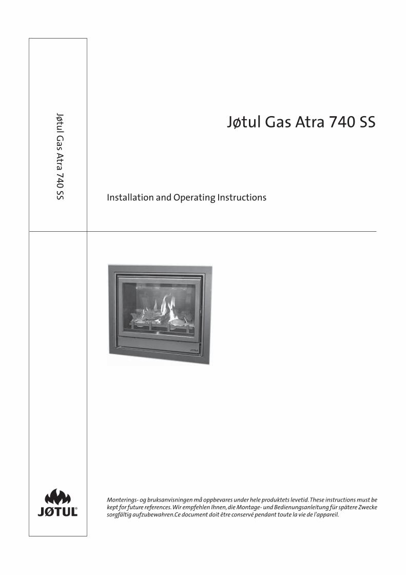
Jøtul Gas Atra 740 SS
Installation and Operating Instructions
Jøtul Gas Atra
74
0 SS
2
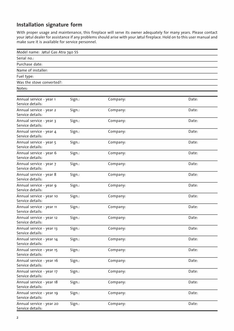
Installation signature formWith proper usage and maintenance, this fireplace will serve its owner adequately for many years. Please contactyour Jøtul dealer for assistance if any problems should arise with your Jøtul fireplace. Hold on to this user manual andmake sure it is available for service personnel.
Model name: Jøtul Gas Atra 740 SSSerial no.:Purchase date:Name of installer:Fuel type:Was the stove converted?:Notes:
Annual service - year 1 Sign.: Company: Date:Service details:Annual service - year 2 Sign.: Company: Date:Service details:Annual service - year 3 Sign.: Company: Date:Service details:Annual service - year 4 Sign.: Company: Date:Service details:Annual service - year 5 Sign.: Company: Date:Service details:Annual service - year 6 Sign.: Company: Date:Service details:Annual service - year 7 Sign.: Company: Date:Service details:Annual service - year 8 Sign.: Company: Date:Service details:Annual service - year 9 Sign.: Company: Date:Service details:Annual service - year 10 Sign.: Company: Date:Service details:Annual service - year 11 Sign.: Company: Date:Service details:Annual service - year 12 Sign.: Company: Date:Service details:Annual service - year 13 Sign.: Company: Date:Service details:Annual service - year 14 Sign.: Company: Date:Service details:Annual service - year 15 Sign.: Company: Date:Service details:Annual service - year 16 Sign.: Company: Date:Service details:Annual service - year 17 Sign.: Company: Date:Service details:Annual service - year 18 Sign.: Company: Date:Service details:Annual service - year 19 Sign.: Company: Date:Service details:Annual service - year 20 Sign.: Company: Date:Service details:
3
Jøtul Gas Atra 740
Single Side
Decorative Gas Fuel EffectAppliance
Countries of destination: AT, CH, DK,ES, FI, FR, GB, GR, IE, IT, NL, NO, PT, SE.
Independently Tested to EN613
Only to be used with the gas type andpressure stated on the data plate affixed tothe appliance.
Keep these instructions in a safe place forfuture use.
Jøtul UK Ltd1 The io CentreNash RoadPark Farm NorthRedditchB98 7ASUK
Jøtul France3, chemin du Jubin69570 DARDILLYFrance
Jøtul ASBox 1411N-1602FredrikstadNorway
Table of Contents:
Installation signature form 2
Installation and Use Instructions 41. Product Information ................................................... 42. Flue Requirements ..................................................... 43. Fireplace Opening Requirements ........................... 44. Ventilation ................................................................... 55. Installation of Appliance Firebox ............................ 56. Installation of Gas Burner ....................................... 57. Lighting and Controlling the Fire ............................ 58. IMPORTANT Appliance Control Notes ................... 59. Commissioning ........................................................... 610. Servicing ...................................................................... 611. Fault Finding ............................................................... 6
Instructions for Use 71. Important Notes .......................................................... 72. Important Appliance Control Notes ....................... 73. Lighting and Controlling the Fire ........................... 74. Servicing and Cleaning ............................................. 7
4
Installation and UseInstructions
Important: Before proceeding with installation and useof this appliance, read these instructions carefully. Keepthem in a safe place for future reference.Gas appliances and chimneys require fresh air ventilationto work correctly and safely. Only use this appliance in asufficiently ventilated space. Installation must be incompliance with the local and national rules in force. Ifin doubt seek expert local advice. Check ventilationregularly to make sure it is clear and unobstructed.
This appliance must only be installed by a competentperson. In the UK this means a registered gas fitter only.Failure to observe this could lead to prosecution.
This appliance firebox is designed for use only with theglass panel in position. If the glass is damaged, loose ormissing, the appliance could be dangerous due to leakingproducts of combustion so do not use in this condition.This appliance is intended for decorative use.
This appliance is a gas burning solid fuel effect applianceand as such it gets very hot in operation. No areas aredesigned to be touched during operation other than thecontrol cover door and control knob itself. All other partsof the appliance are ‘working surfaces’ and get hot as apart of their function. Do not touch any areas other thanthe intended controls and always fix a proper fireguardin place when the presence of children, the elderly orinfirm is likely. The glass itself is not a substitute for afireguard and burns can occur from touching this workingsurface and the metal surrounds.
1. Product Information
2. Flue Requirements• A minimum 6" or 150mm diameter flue liner or rigid
wall flue system is required for connection to thisappliance.
• Minimum height of flue from top of appliance is 3m.• The flue must be free of obstructions or dampers. Any
damper must be removed or fixed permanently in theopen position.
• If the chimney has been used for solid fuel or oilburning it must be thoroughly swept and completelycleaned before use.
• The chimney must be free from leaks or damage andcontinuous in its whole length. It must serve only onefireplace.
• Before installing to an existing flue liner, check thatit has a draught by using a smoke match or similar.Investigate if there is no draught.
• No combustible materials are permitted in or near theflue or in contact with the flue liner or top of thefirebox. Failure to comply with this requirement couldlead to a fire hazard.
3. Fireplace Opening Requirements• This appliance is only suitable for installation into
NON-combustible fireplaces or builders openings.• Minimum opening dimensions are 745mm wide,
590mm high and 460mm deep.• Under no circumstances place the appliance on to
carpet or any kind of combustible materials, includingwood.
• Make sure that the room has adequate combustionand flue air supply. Purpose provided ventilation willnormally be required in the UK for the proportion ofthe gas input that is above 7kW.
• Any combustible surrounding materials, includingwallpaper, wooden shelves etc must be a sufficientdistance from the appliance to prevent any risk of
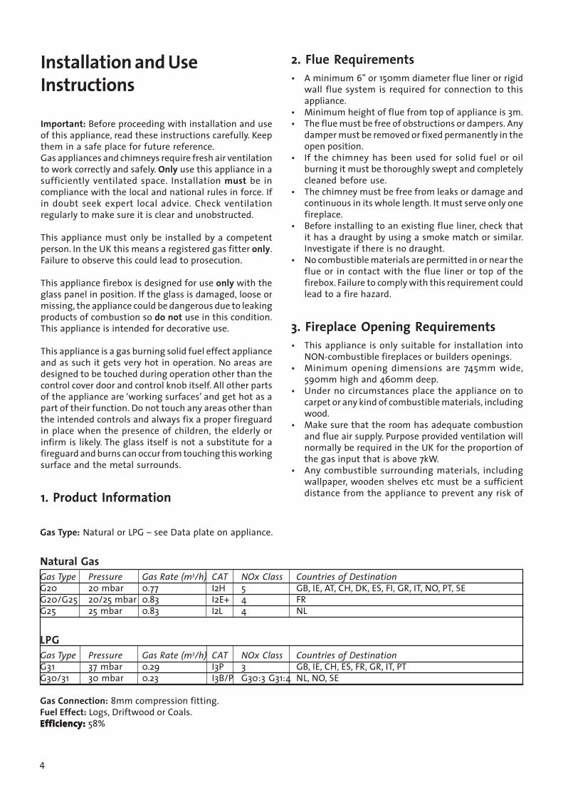
Gas Type: Natural or LPG – see Data plate on appliance.
Natural GasGas Type Pressure Gas Rate (m3/h) CAT NOx Class Countries of DestinationG20 20 mbar 0.77 I2H 5 GB, IE, AT, CH, DK, ES, FI, GR, IT, NO, PT, SEG20/G25 20/25 mbar 0.83 I2E+ 4 FRG25 25 mbar 0.83 I2L 4 NL
LPGGas Type Pressure Gas Rate (m3/h) CAT NOx Class Countries of DestinationG31 37 mbar 0.29 I3P 3 GB, IE, CH, ES, FR, GR, IT, PTG30/31 30 mbar 0.23 I3B/P G30:3 G31:4 NL, NO, SE
Gas Connection: 8mm compression fitting.Fuel Effect: Logs, Driftwood or Coals.Efficiency:Efficiency:Efficiency:Efficiency:Efficiency: 58%
5
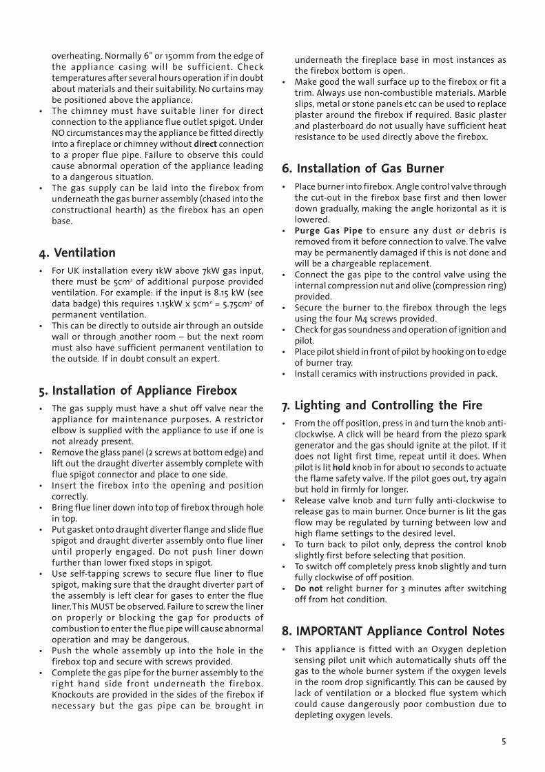
overheating. Normally 6" or 150mm from the edge ofthe appliance casing will be sufficient. Checktemperatures after several hours operation if in doubtabout materials and their suitability. No curtains maybe positioned above the appliance.
• The chimney must have suitable liner for directconnection to the appliance flue outlet spigot. UnderNO circumstances may the appliance be fitted directlyinto a fireplace or chimney without direct connectionto a proper flue pipe. Failure to observe this couldcause abnormal operation of the appliance leadingto a dangerous situation.
• The gas supply can be laid into the firebox fromunderneath the gas burner assembly (chased into theconstructional hearth) as the firebox has an openbase.
4. Ventilation• For UK installation every 1kW above 7kW gas input,
there must be 5cm2 of additional purpose providedventilation. For example: if the input is 8.15 kW (seedata badge) this requires 1.15kW x 5cm2 = 5.75cm2 ofpermanent ventilation.
• This can be directly to outside air through an outsidewall or through another room – but the next roommust also have sufficient permanent ventilation tothe outside. If in doubt consult an expert.
5. Installation of Appliance Firebox• The gas supply must have a shut off valve near the
appliance for maintenance purposes. A restrictorelbow is supplied with the appliance to use if one isnot already present.
• Remove the glass panel (2 screws at bottom edge) andlift out the draught diverter assembly complete withflue spigot connector and place to one side.
• Insert the firebox into the opening and positioncorrectly.
• Bring flue liner down into top of firebox through holein top.
• Put gasket onto draught diverter flange and slide fluespigot and draught diverter assembly onto flue lineruntil properly engaged. Do not push liner downfurther than lower fixed stops in spigot.
• Use self-tapping screws to secure flue liner to fluespigot, making sure that the draught diverter part ofthe assembly is left clear for gases to enter the flueliner. This MUST be observed. Failure to screw the lineron properly or blocking the gap for products ofcombustion to enter the flue pipe will cause abnormaloperation and may be dangerous.
• Push the whole assembly up into the hole in thefirebox top and secure with screws provided.
• Complete the gas pipe for the burner assembly to theright hand side front underneath the firebox.Knockouts are provided in the sides of the firebox ifnecessary but the gas pipe can be brought in
underneath the fireplace base in most instances asthe firebox bottom is open.
• Make good the wall surface up to the firebox or fit atrim. Always use non-combustible materials. Marbleslips, metal or stone panels etc can be used to replaceplaster around the firebox if required. Basic plasterand plasterboard do not usually have sufficient heatresistance to be used directly above the firebox.
6. Installation of Gas Burner• Place burner into firebox. Angle control valve through
the cut-out in the firebox base first and then lowerdown gradually, making the angle horizontal as it islowered.
• Purge Gas Pipe to ensure any dust or debris isremoved from it before connection to valve. The valvemay be permanently damaged if this is not done andwill be a chargeable replacement.
• Connect the gas pipe to the control valve using theinternal compression nut and olive (compression ring)provided.
• Secure the burner to the firebox through the legsusing the four M4 screws provided.
• Check for gas soundness and operation of ignition andpilot.
• Place pilot shield in front of pilot by hooking on to edgeof burner tray.
• Install ceramics with instructions provided in pack.
7. Lighting and Controlling the Fire• From the off position, press in and turn the knob anti-
clockwise. A click will be heard from the piezo sparkgenerator and the gas should ignite at the pilot. If itdoes not light first time, repeat until it does. Whenpilot is lit hold knob in for about 10 seconds to actuatethe flame safety valve. If the pilot goes out, try againbut hold in firmly for longer.
• Release valve knob and turn fully anti-clockwise torelease gas to main burner. Once burner is lit the gasflow may be regulated by turning between low andhigh flame settings to the desired level.
• To turn back to pilot only, depress the control knobslightly first before selecting that position.
• To switch off completely press knob slightly and turnfully clockwise of off position.
• Do not relight burner for 3 minutes after switchingoff from hot condition.
8. IMPORTANT Appliance Control Notes• This appliance is fitted with an Oxygen depletion
sensing pilot unit which automatically shuts off thegas to the whole burner system if the oxygen levelsin the room drop significantly. This can be caused bylack of ventilation or a blocked flue system whichcould cause dangerously poor combustion due todepleting oxygen levels.
6
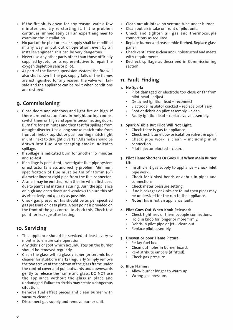
• If the fire shuts down for any reason, wait a fewminutes and try re-starting it. If the problemcontinues, immediately call an expert engineer toexamine the installation.
• No part of the pilot or its air supply shall be modifiedin any way, or put out of operation, even by aninstaller/engineer. This can be very dangerous.
• Never use any other parts other than those officiallysupplied by Jøtul or its representatives to repair theoxygen depletion sensor pilot.
• As part of the flame supervision system, the fire willalso shut down if the gas supply fails or the flamesare extinguished for any reason. The valve will fail-safe and the appliance can be re-lit when conditionsare restored.
9. Commissioning• Close doors and windows and light fire on high. If
there are extractor fans in neighbouring rooms,switch them on high and open interconnecting doors.Burn fire for 5 minutes and then test for spillage fromdraught diverter. Use a long smoke match tube fromfront of firebox top slot or push burning match rightin until next to draught diverter. All smoke should bedrawn into flue. Any escaping smoke indicatesspillage.
• If spillage is indicated burn for another 10 minutesand re-test.
• If spillage is persistent, investigate flue pipe systemor extractor fans etc and rectify problem. Minimumspecification of flue must be 3m of 150mm (6")diameter liner or rigid pipe from the flue connector.
• A smell may be emitted from the fire when first useddue to paint and materials curing. Burn the applianceon high and open doors and windows to burn this offas effectively and quickly as possible.
• Check gas pressure. This should be as per specifiedgas pressure on data plate. A test point is provided onthe front of the gas control to check this. Check testpoint for leakage after testing.
10. Servicing• This appliance should be serviced at least every 12
months to ensure safe operation.• Any debris or soot which accumulates on the burner
should be removed regularly.• Clean the glass with a glass cleaner (or ceramic hob
cleaner for stubborn marks) regularly. Simply removethe two screws at the bottom of the glass frame underthe control cover and pull outwards and downwardsgently to release the frame and glass. DO NOT usethe appliance without the glass in place andundamaged. Failure to do this may create a dangeroussituation.
• Remove fuel effect pieces and clean burner withvacuum cleaner.
• Disconnect gas supply and remove burner unit.
• Clean out air intake on venture tube under burner.• Clean out air intake on front of pilot unit.• Check and tighten all gas and thermocouple
connections as required.• Replace burner and reassemble firebed. Replace glass
panel.• Check ventilation is clear and unobstructed and meets
with requirements.• Recheck spillage as described in Commissioning
section.
11. Fault Finding1. No Spark:
• Pilot damaged or electrode too close or far frompilot head - adjust.
• Detached ignition lead – reconnect.• Electrode insulator cracked – replace pilot assy.• Soot or debris on pilot assembly – clean.• Faulty ignition lead – replace valve assembly.
2. Spark Visible But Pilot Will Not Light:• Check there is gas to appliance.• Check restrictor elbow or isolation valve are open.• Check pipe work is clean – including inlet
connection.• Pilot injector blocked – clean.
3. Pilot Flame Shortens Or Goes Out When Main BurnerLit:• Insufficient gas supply to appliance – check inlet
pipe work.• Check for kinked bends or debris in pipes and
connections.• Check meter pressure setting.• If no blockages or kinks are found then pipes may
be undersized for the run to the appliance.• Note: This is not an appliance fault.
4. Pilot Goes Out When Knob Released:• Check tightness of thermocouple connections.• Hold in knob for longer or more firmly.• Debris in pilot pipe or jet – clean out.• Replace pilot assembly.
5. Uneven or poor Flame Picture.• Re-lay fuel bed.• Clean out holes in burner board.• Re-distribute embers (if fitted).• Check gas pressure.
6. Blue Flames:• Allow burner longer to warm up.• Wrong gas pressure.
7
Instructions for Use
1. Important Notes
Before proceeding with use of this appliance, read theseinstructions carefully. Keep them in a safe place for futurereference. Make a note of your installers name, addressand registration number for future reference. Thisappliance is primarily intended for decorative purposesand not as a main heating unit.
Gas appliances and chimneys require fresh air ventilationto work correctly and safely. ONLY use this appliance in asufficiently ventilated space. Installation MUST be incompliance with the local and national rules in force. Ifin doubt seek expert local advice. Check ventilationregularly to make sure it is clear and unobstructed.
This appliance must only be installed by a competentperson. In the UK this means a registered gas fitter ONLY.Failure to observe this could lead to prosecution.
This appliance firebox is designed for use ONLY with theglass panel in position. If the glass is damaged, loose ormissing, the appliance could be dangerous due to leakingproducts of combustion so Do Not use in this condition.
This appliance is a gas burning solid fuel effect applianceand as such it gets very hot in operation. No areas aredesigned to be touched during operation other than thecontrol cover door and control knob itself. All other partsof the appliance are ‘working surfaces’ and get hot as apart of their function. Do not touch any areas other thanthe intended controls and always fix a proper fireguardin place when the presence of children, the elderly orinfirm is likely. The glass itself is not a substitute for afireguard and burns can occur from touching this workingsurface and the metal surrounds.
2. Important Appliance Control Notes• This appliance is fitted with an oxygen depletion
sensing pilot unit which automatically shuts off thegas to the whole burner system if the oxygen levelsin the room drop significantly. This can be caused bylack of ventilation or a blocked flue system whichcould cause dangerously poor combustion due todepleting oxygen levels.
• If you suspect flue gases are coming into the room,call out your installer to check the safety of theinstallation.
• If the fire shuts down for any reason, wait a fewminutes and try re-starting it. If the problemcontinues, immediately call an expert engineer toexamine the installation.
• As part of the flame supervision system, the fire willalso shut down if the gas supply fails or the flames
are extinguished for any reason. The valve will fail-safe and the appliance can be re-lit when conditionsare restored.
3. Lighting and Controlling the Fire• From the off position, press in and turn the knob anti-
clockwise. A click will be heard from the piezo sparkgenerator and the gas should ignite at the pilot. If itdoes not light first time, repeat until it does. Whenpilot is lit hold knob in for about 10 seconds to actuatethe flame safety valve. If the pilot goes out, try againbut hold in firmly for longer.
• Release valve knob and turn fully anti-clockwise torelease gas to main burner. Once burner is lit the gasflow may be regulated by turning between low andhigh flame settings to the desired level.
• To turn back to pilot only, depress the control knobslightly first before selecting that position.
• To switch off completely press knob slightly and turnfully clockwise of off position.
• DO NOT relight burner for 3 minutes after switchingoff from hot condition.
4. Servicing and Cleaning• The appliance must be serviced every 12 months
minimum.• Any debris or soot which accumulates on the burner
should be removed regularly (only when cold!).• If local regulations demand it, the flue liner should
be cleaned as required.• Clean the glass inside and out (only when cold!) with
a glass cleaner (or ceramic hob cleaner for stubbornmarks) regularly. Simply remove the two screws at thebottom of the glass frame under the control coverand pull outwards and downwards gently to releasethe frame and glass. Do Not use the appliance withoutthe glass in place and undamaged. Failure to do thismay create a dangerous situation.
• Remove fuel effect pieces (including embers whereprovided) and clean burner with vacuum cleaner.
• Re-lay fuel effect as shown in the diagrams. Do notre-lay in any other way as this can seriously affectoperation.
• Clean paintwork and trims with a damp cloth onlywhen cold! Do not use abrasive or chemical cleaners.
8
Jøtul arbeider kontinuerlig for om mulig å forbedre sine produkter, og vi forbeholder ossretten til å endre spesifikasjoner, farger og utstyr uten nærmere kunngjøring.
Jøtul bemüht sich ständig um die Verbesserung seiner Produkte, deshalb könnenSpezifikationen, Farben und Zubehör von den Abbildungen und den Beschreibungen in derBroschüre abweichen.
Jøtul pursue a policy of constant product development. Products supplied may thereforediffer in specification, colour and type of accessories from those illustrated and described inthe brochure.
Jøtul vise sans cesse à améliorer ses produits. C’est pourquoi, il se réserve le droit de modifierles specifications, couleurs et équipements sans avis prélable.
KvalitetJøtul AS arbeider etter et kvalitetssikringssystem basert på NS-EN ISO 9001 for utvikling,produksjon og salg av ildsteder. Vår kvalitetspolitikk skal gi kundene den trygghet ogkvalitetsopplevelse som Jøtul har stått for siden bedriftens historie startet i 1853.
QualitätJøtul AS hat ein Qualitätssicherungssystem, das sich bei Entwicklung, Produktion undVerkauf von Öfen und Kaminen nach NS-EN ISO 9001 richtet. Diese Qualitätspolitikvermittelt unseren Kunden ein Gefühl von Sicherheit und Qualität, für das Jøtul mit seinerlangjährigen Erfahrung seit der Firmengründung im Jahre 1853 steht.
QualityJøtul AS has a quality system that conforms to NS-EN ISO 9001 for product development,manufacturing, and distribution of stoves and fireplaces. This policy gives our customersquality and safety piece of mind as a result of Jøtul’s vast experience dating back to whenthe company first started in 1853.
QualitéLe système de contrôle de la qualité de Jøtul AS est conforme à la norme NS-EN ISO 9001relative à la conception, à la fabrication et à la distribution de poêles, foyers et inserts. Cettepolitique nous permet d’offrir à nos clients une qualité et une sécurité reposant sur la vasteexpérience accumulée par Jøtul depuis sa création en 1853.
Sistema di qualitàLa Società Jøtul AS è in possesso di una sistema di qualità in conformità con il sistema NS-ENISO 9001 per lo sviluppo e progettazione di nuovi prodotti, la loro fabbricazione e ladistribuzione di stufe e caminetti. Questa certificazione, che assicura ai nostri clienti qualitàe sicurezza, è il risultato della vasta esperienza che la Jøtul ha acquisito negli anni intercorsidalla sua fondazione nel 1853.
Dette ildstedet er kontrollert av:Dieses Produkt ist geprüft von:
This product has been controlled by:Ce produit a été contrôlé par :
Questo prodotto è stato controllato da:
________________________ ___________________Date: Sign:
Cat.no. 221234D
raw.no. 4-4319-P00
Aug. 2004
Jøtul AS,P.o. box 1411N-1602 Fredrikstad,Norway