
Manual Operare Delta Blower G5 En
56
ENGLISH AERZENER MASCHINENFABRIK GMBH G4-006 J EN 174 676 000 05-2010 Operating- and installation instructions Positive displacement blower unit
-
Upload
clius39coco -
Category
Documents
-
view
556 -
download
24
description
suflanta delta blower
Transcript of Manual Operare Delta Blower G5 En

ENG
LISH
G4-006 J ENTranslation of the original instructions
1
A E R Z E N E R M A S C H I N E N F A B R I K
G M B H
G4-006 J EN174 676 000 05-2010
Operating- and installation instructionsPositive displacement blower unit
ENG
LISH
G4-006 J ENTranslation of the original instructions
2
Die INFO-Seite ist vor der Inbetriebnahme durchzulesen. Dort evtl. vermerkte Hinweise und Änderungen sind durchzuführen.
Read the INFORMATION sheet prior to commissioning. Possible notes and changes indicated herein are to be effected.
La page INFO est à lire avant la mise en route. Y apporter éventuellement des annotations et modifications.
De INFO-Bladzijde moet voor de inbedrijfname worden doorgelezen. Daar eventueel opgeschreven aanwijzingen en modificaties moeten worden uitgevoerd.
Prima della messa in esercizio leggere la pagina INFO, ed eseguire eventuali istruzioni o modifiche indicate.
Antes de proceder a la puesta en marcha, leer detenidamente la página informativa y cumplir eventuales indicaciones y modificaciones indicadas en la misma.
A página de informações deve ser lida antes da colocação em funcionamento. As eventuais indicações e alterações aí mencionadas devem ser respeitadas.
INFO-siden skal læses igennem inden idriftsættelsen. Evt. anvisninger og ændringer der står dér skal gennemføres.
Les INFO-siden før igangsetting. Anvisninger og endringer som står oppført der, skal utføres.
Läs igenom INFO-sidan före idrifttagning. Eventuellt angivna anvisningar eller förändringar skall genomföras.
Pidätämme oikeuden painovirheisiin, erehdyksiin sekä teknisiin muutoksiin..
Druckfehler, Irrtümer sowie technische Änderungen sind vorbehalten.
We are not liable for misprints, errors, and we reserve the right to make technical changes.
Sous réserve de fautes d‘impression, d‘erreurs et de modifications techniques.
Drukfouten, vergissingen en technische wijzigingen voorbehouden.
Salvo error u omisión. Reservado el derecho a realizar modificaciones técnicas.
Salvo errori di stampa, incorrettezze e modifiche tecniche.
Reservamo-nos o direito a erros de impressão, enganos e alterações técnicas.
Der tages forbehold for trykfejl, fejl og tekniske ændringer.
Med forbehold om trykkfeil, feiltagelser og tekniske endringer.
Tryckfel, övriga fel samt tekniska förändringar förbehålles.
INFO-sivu on luettava ennen käyttöönottoa. Siellä ilmoitetut mahdolliset muutokset tai lisäykset on otettava huomioon
ENG
LISH
G4-006 J ENTranslation of the original instructions
3
ENGLISH 1 - 52Translation of the original instructions
VerschleißteilzeichnungenWe a r i n g p a r t s d r a w i n g sPlans des pièces d 'usureTekening waarop aangegevenDisegno parti soggette ad usuraDibujo de pieza de desgaste
Ersatzteil-Liste Spare parts list Pièces de rechange Reservedelen Repuestos para tamaños de soplantesParti di ricambi
Konformitäts-ErklärungDeclarat ion of ConformityC e r t i f i ca t d e co n fo rm i t éEG-Verklaring van over-een-s temming voor mach ines Declaración de conformidadDichiarazione di conformità
Leistungsdaten Performance data Performances Capaciteitsgegevens Datos de servicio Dati di esercizio
INFO - SeiteInformation sheetPage infosInfo bladzijdePagina Informa-tivaInformazioni
I n
h a
l t
/
C o
n t
e n
t s
A
erze
ner M
asch
inen
fabr
ikA
btei
lung
Tec
hnis
che
Dok
umen
tatio
nTe
chni
sche
Illu
stra
tion
& R
edak
tion
H.N
icke
l Tech
nisc
her A
utor
54 - 55
53
ENG
LISH
G4-006 J ENTranslation of the original instructions
4 (Herr Irtel) Die
se K
onfo
rmitä
tser
klär
ung
ist m
it de
m In
kraf
ttret
en d
er M
asch
inen
richt
linie
200
6/42
/EG
ab
dem
29-
12-2
009
gülti
g.Th
is d
ecla
ratio
n of
con
form
ity a
pplie
s w
hen
the
Mac
hine
Dire
ctiv
e 20
06/4
2/E
C c
omes
into
forc
e on
29-
12-2
009.
Cet
te d
écla
ratio
n de
con
form
ité e
st v
alab
le à
par
tir d
u 29
/12/
2009
ave
c l‘e
ntré
e en
vig
ueur
de
la d
irect
ive
Mac
hine
s 20
06/4
2/C
E.
A3-050 E XT1 von 2 08-2009
Die Konformitätserklärung für diese Drehkolbenmaschine wird von den technischen Angaben im Kapitel „Leistungsdaten“ ergänzt. Die dort erwähnten Angaben identifizieren das Produkt und sind in Verbindung mit dieser Konformitätserklärung zu verwenden.
The declaration of conformity for the rotary piston machine supplimented by the technical specification in the chapter „Performance data“. The data mentioned there identify the product and must be used in association with this declaration of conformity.
La déclaration de conformité de cette machine à pistons rotatifs est complétée par les indications techniques du chapitre « Caractéristiques de puissance ». Les indications qui y sont données identifient le produit et sont à mettre en relation avec la présente déclaration de conformité.
Konformitätserklärung für Maschinen gemäß Maschinenrichtlinie 2006/42/EGDeclaration of conformity for machines in accordance with Machine Directive 2006/42/EC
Déclaration de conformité pour machines selon la directive Machines 2006/42/CE
Unterschrift des HerstellersSignature of the manufacturerSignature du constructeur
Leiter Techn. AbteilungHead of the dept.Directeur technique
DEUTSCH Originalkonformitätserklärung Hiermit erklärt der Hersteller: Aerzener Maschinenfabrik GmbH, Reherweg 28, D-31855 Aerzendass die Maschine konform ist mit den Bestimmungen der folgenden Richtlinien:Maschinenrichtlinie 2006/42/EG Elektromagnetische Verträglichkeit 2004/108/EG.Druckgeräterichtlinie 97/23/EGDie Schutzziele der Niederspannungsrichtlinie wurden gemäß Anhang I, Nr. 1.5.1 der Maschinenrichtlinie eingehalten.Die zutreffenden harmonisierten Normen der Maschinenrichtlinie wurden angewandt.Die Konformitätserklärung bezieht sich auf den vom Hersteller in Verkehr gebrachten originalen Maschinen-zustand. Bei nachträglich durchgeführten Veränderungen und/oder nachträglich vorgenommenen Eingriffen erlischt diese Konformitätserklärung.Die zur Maschine gehörenden speziellen technischen Unterlagen nach Anhang VII Teil A wurden erstellt.Dokumentationsverantwortlicher: Herr Irtel Aerzen, 18-08-2009
ENGLISH Translation of the original declaration of conformityThe manufacturer: Aerzener Maschinenfabrik GmbH, Reherweg 28, D-31855 Aerzenhereby declares that the machine conforms to the provisions of the following directives:Machine Directive 2006/42/EC. Electromagnetic Compatibility 2004/108/EC.Pressure Equipment Directive 97/23 ECThe safety objectives of the Low Voltage Directive have been complied with according to Appendix I, No. 1.5.1 of the Machine Directive.The applicable harmonised standards of the Machine Directive have been applied.The declaration of conformity refers to the machine in its original state as marketed by the manufacturer. Any changes introduced subsequently and/or interventions carried out subsequently will void this declaration of conformity.The special technical documents for the machine in accordance with Appendix VII Part A have been cre-ated.Responsible for documentation: Herr Irtel Aerzen, 18-08-2009
FRANÇAIS Traduction de la déclaration de conformité d‘origineLe fabricant : Aerzener Maschinenfabrik GmbH, Reherweg 28, D-31855 Aerzendéclare par la présente que la machine est conforme aux dispositions des directives suivantes :Directive Machines 2006/42/CE Compatibilité électromagnétique 2004/108/CEDirective Équipements sous pression 97/23/CELes objectifs de protection de la directive Basse tension ont été respectés conformément à l‘annexe I, n° 1.5.1 de la directive Machines.Les normes harmonisées concernées de la directive Machines ont été appliquées.La présente déclaration de conformité se rapporte à l‘état d‘origine de la machine tel que mis en circulation par le fabricant. Cette déclaration de conformité est rendue caduque par toute modification et/ou intervention ultérieure.La documentation technique pertinente pour la quasi-machine a été constituée conformément à l‘annexe VII partie A.Responsable de la documentation : Monsieur Irtel Aerzen, 18-08-2009
ENG
LISH
G4-006 J ENTranslation of the original instructions
5Die
se K
onfo
rmitä
tser
klär
ung
ist m
it de
m In
kraf
ttret
en d
er M
asch
inen
richt
linie
200
6/42
/EG
ab
dem
29-
12-2
009
gülti
g.Th
is d
ecla
ratio
n of
con
form
ity a
pplie
s w
hen
the
Mac
hine
Dire
ctiv
e 20
06/4
2/E
C c
omes
into
forc
e on
29-
12-2
009.
Cet
te d
écla
ratio
n de
con
form
ité e
st v
alab
le à
par
tir d
u 29
/12/
2009
ave
c l‘e
ntré
e en
vig
ueur
de
la d
irect
ive
Mac
hine
s 20
06/4
2/C
E.
(Herr Irtel)
Dez
e co
nfor
mite
itsve
rkla
ring
is g
eldi
g bi
j de
inw
erki
ngtre
ding
van
de
mac
hine
richt
lijn
2006
/42/
EG
van
af 2
9-12
-200
9.
Est
a de
clar
ació
n de
con
form
idad
obt
endr
á va
lidez
con
la e
ntra
da e
n vi
gor d
e la
Dire
ctiv
a de
Máq
uina
s 20
06/4
2/C
E, a
par
tir d
el 2
9.12
.200
9.
Con
l‘en
trata
in v
igor
e de
lla D
iretti
va m
acch
ine
2006
/42/
CE
la p
rese
nte
Dic
hiar
azio
ne d
i con
form
ità è
val
ida
a pa
rtire
dal
29-
12-2
009.
A3-050 E XT2 von 2 08-2009
De conformiteitsverklaring voor deze roterende zuigercompressor wordt aangevuld door de technische informatie in het hoofdstuk „Specificaties“. Aan de hand van de daar vermelde informatie wordt het product geïdentificeerd en de informatie moet in combinatie met deze conformiteitsverklaring toegepast worden.La declaración de conformidad para esta máquina de émbolos giratorios es complementada por los datos técnicos que se encuentran en el capítulo “Datos de potencia”.
Los datos ahí indicados identifican al producto y se deberán utilizar conjuntamente con esta declaración de conformidad.La Dichiarazione di conformità per la presente macchina a pistoni rotanti è integrata dai dati tecnici riportati nel capitolo „Dati di prestazione“ Le informazioni incluse in quel capitolo identificano il prodotto e devono essere utilizzate insieme alla presente Dichiarazione di conformità.
Conformiteitsverklaring voor machines conform machinerichtlijn 2006/42/EG
Declaración de conformidad para máquinas, de conformidad con la Directiva de Máquinas 2006/42/CE
Dichiarazione di conformità per macchine secondo la Direttiva macchine 2006/42/CE
Handtekening van de fabrikantFirma del fabricanteFirma del fornitore
Hoofd technische afdelingDirector Dpto, TécnicoResponsabile reparto tecnico
NEDERLANDS Vertaling van de originele conformiteitsverklaringHierbij verklaart de fabrikant: Aerzener Maschinenfabrik GmbH, Reherweg 28, D-31855 Aerzendat de machine voldoet aan de bepalingen van de volgende richtlijnen:machinerichtlijn 2006/42/EG elektromagnetische compatibiliteit 2004/108/EG.richtlijn drukapparatuur 97/23/EGDe doelstellingen voor veiligheid van de laagspanningsrichtlijn zijn conform bijlage I, nr. 1.5.1 van de machi-nerichtlijn nageleefd.De betreffende geharmoniseerde normen van de machinerichtlijn zijn toegepast.De conformiteitsverklaring heeft betrekking op de originele machinetoestand die door de fabrikant in omloop is gebracht. Bij veranderingen en/of ingrepen die naderhand uitgevoerd zijn, komt deze conformiteitsverklaring te verval-len.De speciale, bij de machine horende, technische documentatie conform bijlage VII deel A is opgesteld.Verantwoordelijk voor de documentatie: de heer Irtel Aerzen, 18-08-2009
ESPAÑOL Traducción de la declaración de conformidad originalPor la presente, el fabricante: Aerzener Maschinenfabrik GmbH, Reherweg 28, D-31855 Aerzendeclara, que la máquina cumple con las disposiciones de las siguientes directivas:Directiva de Máquinas 2006/42/CE Compatibilidad Electromagnética 2004/108/CEDirectiva de Equipos a Presión 97/23/CELos objetivos en materia de seguridad establecidos en la Directiva de Bajo Voltaje se han aplicado según el anexo I, núm. 1.5.1 de la Directiva de Máquinas.También se han aplicado las normas armonizadas correspondientes de la Directiva de Máquinas.La declaración de conformidad se refiere al estado original de la máquina que el fabricante comercializa. En el caso de realizar modificaciones y/u operaciones posteriores, la declaración perderá toda validez.La documentación técnica correspondiente a la máquina, de conformidad con el anexo VII, parte A ha sido elaborada.Responsable de la documentación: Sr. Irtel Aerzen, 18.08.2009
ITALIANO Traduzione della dichiarazione di conformità originaleCon la presente dichiarazione il produttore: Aerzener Maschinenfabrik GmbH, Reherweg 28, D-31855 Aerzendichiara che la macchina è conforme alle disposizioni delle seguenti direttive:Direttiva macchine 2006/42/CE Compatibilità elettromagnetica 2004/108/CEDirettiva sulle attrezzature a pressione 97/23/CEGli obiettivi di sicurezza della Direttiva bassa tensione sono stati rispettati secondo l’allegato I, n. 1.5.1 della Direttiva macchine.Sono state applicate le relative norme armonizzate della Direttiva macchine.La dichiarazione di conformità si riferisce allo stato della macchina originale messa in circolazione dal pro-duttore. In caso di modifiche eseguite successivamente e/o di interventi eseguiti in un secondo momento, decade l’obbligo della dichiarazione.È stata predisposta la documentazione tecnica speciale relativa alla macchina secondo l’Allegato VII Parte A.Responsabile della documentazione: Sig. Irtel Aerzen, 18-08-2009
ENG
LISH
G4-006 J ENTranslation of the original instructions
6
Ersatzteile, spare parts, pièces dé tachée, onderdelen, repuestos, pezzi di ricambio
- AERZENER MASCHINENFABRIK -
Ersatz- und Zubehörteile Es wird darauf hingewiesen, dass nicht von uns gelieferte Originalteile und Zubehör auch nicht von uns geprüft und freigegeben sind. Der Einbau oder Anbau sowie die Verwendung solcher Produkte kann daher unter Umständen konstruktive vorgegebene Eigenschaften der Anlagen beeinflussen. Für Schäden, die durch Verwendung von nicht Originalteilen und Zubehör entstehen, ist jede Haftung des Herstellers ausge-schlossen.
Spare parts and accessoriesWe draw your attention to the fact that original parts and accessories not supplied by us are also not inspec-ted and released by us. Therefore, the installation and application of such products might influence under certain circumstances constructively stipulated properties of the plants. Consequential damages due to application of non-original parts and accessories release the manufacturer from any warranty and liability.
Accessoires et pièces de rechange Nous attirons votre attention sur le fait que les accessoires et pièces d’origine n’étant pas de notre fourniture ne peuvent être controlés et pris en considératoin lors d’une réclamation. L’intégration ou le montage ainsi que l’utilisation de telles pièces peut influencer sous certaines conditions les caractéristiques et performances de la machine. Pour tout dommage causé du fait de pièces n’étant pas d’origine ou de montage erroné, nous déclinons toute responsabilité.
Reservedelen en toebehorenEr wordt uitdrukkelijk op gewezen dat niet door ons geleverde originele delen en toebehoren ook niet door ons getest en vrijgegeven zijn. De in of aanbouw alsmede de toepassing van zulke producten kan der-halve onder zekere omstandigheden constructief gegeven eigenschappen van de installatie beïnvloeden. Voor schaden, die door gebruik van niet originele delen en accessoires ontstaan, is iedere aansprakelijkheid jegens de fabrikant uitgesloten.
Ricambi e accessoriFacciamo presente che i pezzi e ricambi originali non forniti da noi, non sono da noi controllati e accettati. Il montaggio o l’impiego di questi prodotti può in certe circostanze provocare influenze sul cattivo funziona-mento dell’impianto. Danni causati dall’impiego di parti e ricambi non originali esonerano il fornitore da ogni garanzia.
Piezas de repuesto y accesoriosIndicamos expresamente, que aquellos repuestos y/o accesorios no suministrados por nosotros no están comprobados ni homologados por Aerzen. Su montaje, así como su utilización pueden tener incidencia en las características prefijadas de la instalación. Por lo tanto no asumimos garantía ni responsabilidad alguna sobre éstas piezas y de los eventuales daños posteriores y/o alteraciones de las calidades y prestaciones de origen. Para daños originados por la utilización de piezas y accesorios no originales, se excluye cualquier responsabilidad por parte del fabricante.
ENG
LISH
G4-006 J ENTranslation of the original instructions
7
Leistungsdaten Performance data
Aerzener Maschinenfabrik

ENG
LISH
G4-006 J ENTranslation of the original instructions
8
Ersatzteilliste / spare parts list
Auftrags-Nr.order no.
Typtype
Fabrik-Nr.serial no.
Kundenbestell-Nr.Customer‘s order no.
LieferanschriftDispatch address
Rechnungsan-schriftInvoice address
Pos. Stückzahl / quantity
Pos. Stückzahl / quantity
10 150
20 160
30 170
40 180
50 190
60 200
70 210
80 220
90 230
100 240
110 250
120 260
130 270
140 280
Bitte richten Sie Ihre Bestellung, an die für Sie zuständige Aerzener Vertretung / -Gesellschaft. Abruf unter (++49) 0 51 54 81 192Please send your ordering to the Aerzen representation / -company responsible for your country.Fax polling ++49 (0) 515481192
Aerzener Maschinenfabrik
DN 50
Aer
zene
r Mas
chin
enfa
brik
Abt
eilu
ng T
echn
isch
e D
okum
enta
tion
/ TN
Tech
nisc
he Il
lust
ratio
n &
Red
aktio
nH
.Nic
kel T
echn
isch
er A
utor
ENG
LISH
G4-006 J ENTranslation of the original instructions
9
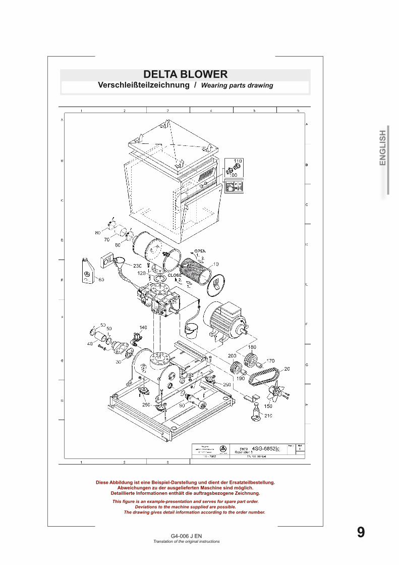
DELTA BLOWERVerschleißteilzeichnung / Wearing parts drawing
Diese Abbildung ist eine Beispiel-Darstellung und dient der Ersatzteilbestellung. Abweichungen zu der ausgelieferten Maschine sind möglich.
Detaillierte Informationen enthält die auftragsbezogene Zeichnung.
This figure is an example-presentation and serves for spare part order. Deviations to the machine supplied are possible.
The drawing gives detail information according to the order number.
ENG
LISH
G4-006 J ENTranslation of the original instructions
10
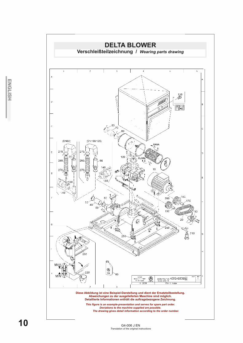
DELTA BLOWERVerschleißteilzeichnung / Wearing parts drawing
Diese Abbildung ist eine Beispiel-Darstellung und dient der Ersatzteilbestellung. Abweichungen zu der ausgelieferten Maschine sind möglich.
Detaillierte Informationen enthält die auftragsbezogene Zeichnung.
This figure is an example-presentation and serves for spare part order. Deviations to the machine supplied are possible.
The drawing gives detail information according to the order number.
ENG
LISH
G4-006 J ENTranslation of the original instructions
11
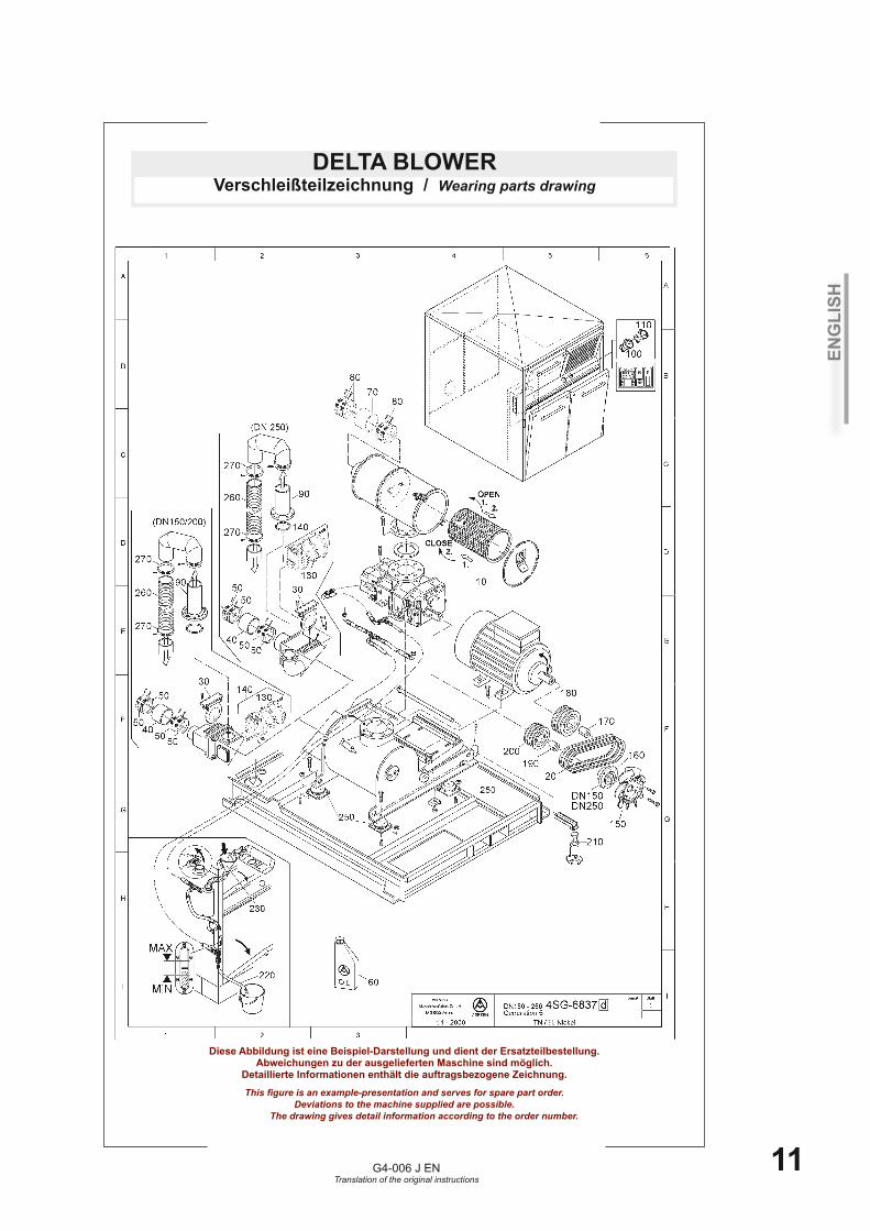
DELTA BLOWERVerschleißteilzeichnung / Wearing parts drawing
Diese Abbildung ist eine Beispiel-Darstellung und dient der Ersatzteilbestellung. Abweichungen zu der ausgelieferten Maschine sind möglich.
Detaillierte Informationen enthält die auftragsbezogene Zeichnung.
This figure is an example-presentation and serves for spare part order. Deviations to the machine supplied are possible.
The drawing gives detail information according to the order number.
ENG
LISH
G4-006 J ENTranslation of the original instructions
12
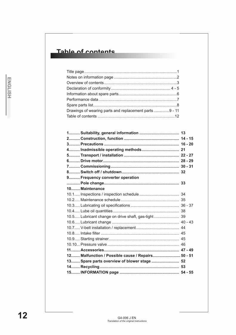
Title page ....................................................................................1Notes on information page .........................................................2Overview of contents ..................................................................3Declaration of conformity ...................................................... 4 - 5Information about spare parts.....................................................6Performance data .......................................................................7Spare parts list............................................................................8Drawings of wearing parts and replacement parts ..............9 - 11Table of contents ......................................................................12
1.......... Suitability, general information .................................... 132.......... Construction, function .................................................. 14 - 153.......... Precautions .................................................................... 16 - 204.......... Inadmissible operating methods .................................. 215.......... Transport / installation .................................................. 22 - 276.......... Drive motor ..................................................................... 28 - 297.......... Commissioning .............................................................. 30 - 318.......... Switch off / shutdown .................................................... 329.......... Frequency converter operation............ Pole change .................................................................... 3310........ Maintenance10.1..... Inspections / inspection schedule .................................... 3410.2..... Maintenance schedule ..................................................... 3510.3..... Lubricating oil specifications ............................................ 36 - 3710.4..... Lube oil quantities ............................................................ 3810.5..... Lubricant change on drive shaft, gas-tight ....................... 3910.6..... Lubricant change ............................................................. 40 - 4310.7..... V-belt installation / replacement ....................................... 4410.8..... Intake filter ....................................................................... 4510.9..... Starting strainer................................................................ 4510.10... Pressure valve ................................................................. 4611. ....... Accessories .................................................................... 47 - 4912........ Malfunction / Possible cause / Repairs......................... 50 - 5113........ Spare parts overview of blower stage ......................... 5214........ Recycling ........................................................................ 5315........ INFORMATION page ...................................................... 54 - 55
Table of contents
ENG
LISH
G4-006 J ENTranslation of the original instructions
13
Suitability/General information
The German version of these instructions is the “Original instructions”.Any version in a language other than German is a “Translation of the original instruc-tions”.
Aerzener rotary piston machines are suitable for the oil-free conveying and compression of air and, if specially modified versions are used, various other types of gas.
The technical performance limits must be observed if perfect operation of the equip-ment is to be ensured in the long term.The performance limits specified in the order confirmation apply.
The intake temperature t1 specified on the order confirmation serves as the installation site ambient temperature.
Non-observance of the technical performance limits or the safety information shall absolve Aerzener Maschinenfabrik of its warranty obligations and its liability to pay damages or compensation as a result of any consequential damage. The same shall apply to defects that can be traced back to recommended inspections not being per-formed correctly or on time.
The vibration behaviour of blowers and compressors with mounted belt pulleys or couplings is largely determined by the balance quality of the pistons/rotors as well as the balance of the driving elements.At Aerzener Maschinenfabrik, the piston/rotor driving shafts are balanced using the „half-key balancing“ technique.The belt pulleys/couplings must be used in accordance with the requirements of bal-ancing type „H“.
1

ENG
LISH
G4-006 J ENTranslation of the original instructions
14
2 Construction, functionUnit:The standard unit is delivered with mounted accessories, ready to operate.However, the following additional work must be carried out:
Connect the delivery pipes.•Check the oil level.•Adjust the level, if necessary.•Install the electrical connection.•Install special accessories which are supplied separately, if necessary.•
Service package:An Aerzen service package is available for the delta blower unit. It includes auxiliary equipment and material for filling with oil and lifting the hinged motor mounting plate, for example.
Generation 5/Initial quantity of operating oil: With few exceptions, „fifth generation“ series units are supplied with an initial quantity of operating oil. The lubricating oil is stored in suitable containers located inside the acoustic hood/on the unit. Please take note of the machine type specifications on the lubricating oil container. The initial oil supplied is the exact quantity required by the blower. This means that the oil container may not be completely full. Please observe the machine‘s oil filling quantity and check the level using the markings on the sight glasses found either on the blower and on the acoustic hood, as appropriate.Please retain the lubricating oil container until the first oil change so that it can be used for catching and collecting the waste oil.
Motor connection:Electrical installation has to be performed by an authorised electrical fitter. The terminal diagram for the motor can be found in the cover of the terminal box as well as in the accompanying documentation.Connect the motor and control circuit voltage to a common, stable network to ensure that the locking of the power contactor will be disabled if the power supply fails. Avoid voltage fluctuations and dips.Alternative: Install an electronic monitoring relay in parallel with the driving motor which will disable the locking of the power contactor if the power supply fails.A restart should only be possible after a complete machine standstill.
Prerequisites for operating rotary piston machines with asynchronous electric motors on a 3-phase AC supply network:The machine should only be used on stable three-phase supply networks. The voltage and frequency limits must be observed. These are specified in EN 60034-1.Voltage fluctuations/dips beyond the tolerance zone can seriously damage all elements that make up the drive system, e.g. couplings, V-belts, V-belt pulleys, shafts, etc... .If excessive voltage fluctuations arise in the system, Aerzener Maschinenfabrik recommends the following measures in order to prevent the blower, compressor or motor from sustaining damage:- Use suitable protective equipment that will shut down the motor and safeguard it against an automatic restart when inadmissible operating data are detected. Observe also EN 60034-1 and EN 60 204-1.
ENG
LISH
G4-006 J ENTranslation of the original instructions
15
2Base support:The base support is a torsion-stable, cylindrical container that serves as both an absorption-free discharge silencer and as a foundation for the installation of a blower with intake silencer, belt drive, belt guard, hinged motor mounting plate and connection housing. The base support rests on flexible machinery mountings and is to be placed on an even, non-sloping foundation.A pressure valve appropriate to the size of the blower is also mounted on the base sup-port to protect the blower against overload.
Filter silencer:This silencer is a combination of intake-side silencer and intake filter. The filter material is easy to access and, therefore, easy to replace.The degree of contamination/the specifications in the maintenance schedule determine when the filter material is to be replaced.
Connection housing:The connection housing contains a non-return valve that prevents the blower from run-ning in reverse after shut-down.Additionally, a device for no-load start can be mounted on the connection housing.A pressure valve appropriate to the size of the blower is also mounted on this housing to protect the blower against overload.Connect the discharge-side piping to the housing via a rubber sleeve or a compensa-tor.
Function: Aerzen positive displacement blowers are twin-shaft rotating piston machines whose pistons turn against each other uniformly. Timing gears guarantee contact-free running of the rotary pistons. The direction of rotation determines the blower‘s direction of flow, which means there is a discharge-side and an intake-side flange. During operation the conveying medium flows through the intake flange into the housing and is forced into the conveying chambers, which are formed by the pistons and the blower cylinder, towards the discharge side.
Pulsation is reduced by means of interference (patented). The conveying chamber (cylinder) is sealed from the oil chambers (housing cover and gear case) by piston ring labyrinth seals and the driving shaft is sealed by means of one or two radial seal rings.If the oil level is too high, oil can penetrate the conveying chamber in an uncontrolled manner. The compression process creates compression heat. The heat is partly released into the surrounding air via the outer surfaces of the blower and the delivery pipes. Outer surfaces and delivery pipes reach temperatures which can cause unprotected skin to burn.
ENG
LISH
G4-006 J ENTranslation of the original instructions
16
3 Due Care to Be Taken Before and During OperationCAUTION ! Identifies all hazardous situations WARNING ! Indicates direct risk to personnel
Upon arrival/receipt, the rotary piston machine must be checked against the delivery and order documentation to make sure it has not been damaged during transit and is complete.
Work safety regulations, safety information and operating instructions must all be complied with.
Read the INFORMATION SHEET prior to commissioning. Any notes or changes sta-ted on it must be observed.The tasks described below must only be carried out by qualified personnel who are fa-miliar with the operation of the machine and its components, and have been instructed in the relevant safety information.
This rotary piston machine conforms to European safety regulations. Nevertheless, residual technical risks, which could endanger persons and property, may remain. To prevent this, operators must take note of the following safety information:
Assembly of the unitKeep the flange connections sealed during installation.The ingress of dirt, burring, sputtering, liquids or similar must be avoided. Remove the seals and covers on the flanges just before the ducting connection.The rotary piston machine can otherwise be blocked or sustain serious damage.
Information about operating dataThe machine must be used appropriately and in compliance with the regulations, and within its performance limits.The sound pressure level may deviate from that stated in the operating data, depen-ding on the operating state. A sound pressure level in excess of 85 dB(A) may therefo-re occur for a short period of time.
Information about general operationThe general safety and industrial accident prevention regulations set down by law must be taken into account in addition to the information in the operating instructions.The user has an obligation to only operate the machine in perfect, original condition and when it is safe to operate.The rotary piston machine is equipped with electrical energy in order to avoid any hazards that may be caused by electricity. Only trained electrical technicians may work on current-carrying components.Any possibly dangerous electrostatic charging must be avoided and/or enable the discharge of electrical charges with the support of devices. A suitable earthing system must be equipped to protect against possible damage caused by lightning strikes.For operation, the unit must be equipped with one or more EMERGENCY BREAK control units. The EMERGENCY BREAK function must be available and ready for operation at all times, independent of the type of operation.It must be guaranteed that a stopped rotary piston machine can be moved from the
Erst lesen -dann bedienen!
Read first, then operate !
ENG
LISH
G4-006 J ENTranslation of the original instructions
17
3rest position without operating the start function, no matter what the cause. Damaged rotary piston machines or machines that are not in perfect working order must be replaced immediately.Any operation that impairs machine safety is prohibited.The supplier documentation provided with the accessories and the general safety regulations must also be observed.The unit contains rotating components. If their protective equipment, according to the version of the unit, e.g. the acoustic hood, belt guard, coupling guard etc., are not observed or are not used appropriately, there is a risk of injury !Protective equipment such as the belt guard/coupling guard, blower guard, hood elements, electrical safety elements, pressure valves, motor protection/EMERGENCY OFF etc., must not be removed or its operational safety restricted whilst the machine is in operation. Risk of injury !Do not operate when electrical, mechanical or hydraulic connections are defective missing or are not correctly connected.It is expressly prohibited to operate the rotary piston machine without the appropriate protective equipment or safety devices.It is expressly prohibited to remove or modify any protective equipment located on the rotary piston machine, divert it from its intended use, or attach third-party protective equipment.Do not operate the unit if protective equipment such as the belt or coupling guard, acoustic hood elements, pressure valve, etc., is defective or missing. When carrying out work on the unit, the drive motor must be securely disconnected from its power supply.Never look into or touch the discharge opening/side of the pressure valve!There is a risk of injury from decompressing gas escaping at a high speed when the pressure valve is drained. Residual pieces of contaminants, dust particles etc. may escape along with this.Screwed connections should only be retightened while the machine is in a depressuri-sed state or is shut down.The machine must only be used in stable three-phase supply networks. Voltage fluc-tuations/dips beyond the tolerance zone can seriously damage all elements that make up the drive system, e.g. couplings, V-belts, V-belt pulleys, shafts, etc. The operator must use oil of a suitable quality, conforming to the Aerzener lubricating oil specifica-tions. Observe the safety, operating and maintenance information of the drive motor manuf-acturer!
Safety instructions for commissioningThese operating instructions must be read and understand before commissioning the machine.Commissioning must only be carried out by persons with the relevant knowledge and skills.Before switching on the machine, ensure you are familiar with all protection, operation and monitoring elements by referring to these instructions.Before commissioning, the unit must be equipped with a command system with which the machine can be shut down according to the hazard potential in order to return the machine to a safe state.The energy supply to the drive motor must be disconnected as soon as the machine is shut down. If this is not possible, the operating state “Shut down” must be monitored and maintained.Check that the intake side is clean before commissioning. Any evidence of dirt, dust or foreign matter must be removed from the intake area.Compliance with the maintenance schedule is absolutely mandatory.
ENG
LISH
G4-006 J ENTranslation of the original instructions
18
Qualification of operatorsEach person dealing with the installation, operation, maintenance and repair of this unit must have read and understood the operating instructions.The unit must only be operated by trained and authorised personnel. Personnel must be trained according to the operating instructions.Responsibility for operation must be precisely defined in order to prevent any unclear designation of responsibilities.Operators must be proficient, instructed and appointed to the work.Only trained and authorised electrical technicians may work on current-carrying components. The unit must be disconnected from the power supply. Fuses must be disconnected.
Safety instructions in relation to prevailing residual risksThe warning and information signs on the machine must be observed. They provide important information about potential sources of danger.Check that the machine is not damaged in any way before commissioning.Do not operate the unit if electrical connections are damaged, defective or not properly connected.Do not operate the machine with exposed and accessible inlet or discharge sockets, for the following reasons: Rotary piston machines are positive displacement machines which present a risk of injury in the area around the conveying chamber.Only suitable tools that correspond to the respective standards and design of the bolts, nuts and screwed connections must be used.When using cleaning agents and sprays, there is a risk of poisoning from inhalation, and a risk of burning from coming into contact with them.Please refer to the material safety data sheets for the operating materials used. Avoid skin contact with or the swallowing of the lubricant. Risk of poisoning ! Wear protective gloves.Used lubricants are extremely harmful to the environment and can contain noxious materials.Lubricants must be stored and disposed of properly and in an environmentally-friendly manner. The appropriately fitted rotary piston machines must be used for conveying oxygen. A lubricant especially suited for operating with oxygen must be used. Disregarding these warnings is a risk of fire and explosion !Rotary piston machines with separate speed monitoring are equipped with a contact plate on the drive shaft.This contact plate rises above the diameter of the belt pulley and reaches operating speed. Disregarding the separating protective equipment is a risk of shearing !
Warning signs for hazardous operationsRepairs and modifications to the unit must only be carried out in a professional man-ner. If you have any problems, please contact Aerzener After-Sales Service for assi-stance. Before carrying out any retrofitting, servicing or maintenance work that requires the removal of protective equipmen, the power supply must be disconnected and the ma-chine secured to prevent it starting up.When replacing and cleaning the filter material (if present) dust particles and fibres may be released into the ambient air. Do not breathe in these materials. These materials must not reach the unprotected intake area of the rotary piston machine.Lubricating and control oil pipes should only be retightened or opened while the ma-chine is in a depressurised state.Depressurise conveying ducts before attempting to remove them.
3
ENG
LISH
G4-006 J ENTranslation of the original instructions
19
When conveying technical gases, conveying ducts must be rinsed with a neutral gas before disassembly.Note the oil temperature when changing the oil. The oil temperature must rise above 60°C. If it is above 60°C, there is arisk of burns !
Personal protective measuresConveying ducts or components on the discharge side must not be touched without adequate protection. The ducts and components can reach temperatures in excess of 70°C.Risk of burns !If the acoustic hood is open or missing, there is risk of burns when the housing sur-face becomes hot as a result of operation. Protective gloves and clothing must be worn.Close-fitting clothing is required due to the presence of rotating components.Risk of injury !Ear protection must be worn during machine operation.
Information about the installation siteIt is the operator‘s responsibility to use and operate the machine in accordance with its intended use taking into account the local conditions.The machine must only be operated in a suitable, well-ventilated installation site. The installation site must be free from excessive dust, acids, steam and explosive or flam-mable gases.The installation site must be arranged to avoid risks as a result of the ambient air, the medium to be convyed or oxygen deficiency.The installation site must be arranged so that the commissioning of the rotary piston machine does not impose a risk of overheating, fire and/or explosion.The protective equipment provides protection against injury and must not be modified or bypassed.When using diesel or petrol drive motors, there is a risk of poisoning if there is insuf-ficient room ventilation. The installation site must be sufficiently ventilated. The motor manufacturer’s operating instructions must also be observed
Information on operation with an acoustic hoodThe acoustic hood is a structural safety component.During operation with an acoustic hood, all hood elements are to be closed before starting operation and are only to be opened after the motor has been shut down and the fuses removed or switched off.The acoustic hood prevents the risk of injury from rotating and hot components.If the acoustic hood is opened while the machine is operating, there is a risk of injury.When installing and assembling the unit, no sparks or glowing objects caused by, e.g. welding or separating, are allowed to enter the foam in the acoustic hood. Risk of fire ! Risk of glowing embers !Fire regulations must be adhered to for all “hot work operations” close to the unit.
CAUTION ! When commissioning, sparks, glowing or other fire-causing objects could be taken in from the intake airflow and, fanned by the acoustic hood ventilator, set the foam alight. Risk of fire !No welding or separating is to be done on the acoustic hood as sparks or sputtering caused by the applied thermal energy could set the foam alight. Risk of fire ! Risk
3

ENG
LISH
G4-006 J ENTranslation of the original instructions
20
of glowing embers !Depending on the size and increased fire protection regulations, a flame retardant foam would be applied according to the order.
Information about the event of damageIf the unit produces an abnormal and/or unusual sound, the machine must be shut down immediately using the EMERGENCY BREAK function. The energy supply to the drive motor must be disconnected.If the unit is blocked, the energy supply to the drive motor must be immediately dis-connected.The cause of malfunction must be determined.Aerzener Service can be quickly at hand and provide expert troubleshooting for you.The unit must not be taken into operation until it is properly functioning.
3

ENG
LISH
G4-006 J ENTranslation of the original instructions
21
4Inadmissible operating methods
Installation on uneven and / slanting foundations.•Securing transport devices to the acoustic hood, e.g. using eye bolts in the accou-•stic hood element, winding ropes without expansion braces etc.Non-observance of operating data.•Non-observance of maintenance intervals.•Incorrect direction of rotation.•Switching on - during run-down.• - during reverse rotation.•Inadmissible increase in pressure.•Remaining under or exceeding maximum rotational speed.•Exceeding the maximum temperature.•Pole change to lower rotational speed before motor has come to a standstill.•Operating without a properly connected fault indicator / control is not permited. •Risk of total machine damage!Operation without assemblies or with damaged assemblies which serve for the •protection of persons and machine.Overfilling the maximum oil level.•Operation without oil.•
“Reasonably foreseeable misuse” that can result from easily forseeable human behaviour:Operating the machine without having filled the lubricant.•Operating the machine with too much lubricant.•Operating the machine with reduced intake performance, e.g. due to a soiled •intake filter, starting strainer etc.Assembly and commissioning of the rotary piston machine with intake-side and/or •discharge-side flange sealers, protection covers or similar.Insufficient ventilation at the installation site, no insulated lines.•Open fire or sparks created by welding, separating or similar in direct proximity to •the unit. Risk of fire!Operating the machine without an isolated protective device, open belt or coupling •drive. Risk of injury from rotating components!•Taking out the transport securing pin under the hinged motor support during ope-•ration.Only applicable for belt drive machines.•
ENG
LISH
G4-006 J ENTranslation of the original instructions
22
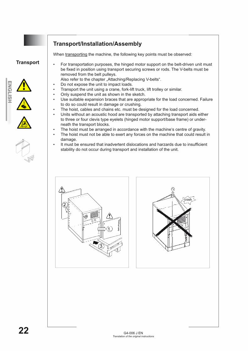
5 Transport/Installation/Assembly When transporting the machine, the following key points must be observed:
For transportation purposes, the hinged motor support on the belt-driven unit must •be fixed in position using transport securing screws or rods. The V-belts must be removed from the belt pulleys. Also refer to the chapter „Attaching/Replacing V-belts“.Do not expose the unit to impact loads.•Transport the unit using a crane, fork-lift truck, lift trolley or similar.•Only suspend the unit as shown in the sketch.•Use suitable expansion braces that are appropriate for the load concerned. Failure •to do so could result in damage or crushing.The hoist, cables and chains etc. must be designed for the load concerned.•Units without an acoustic hood are transported by attaching transport aids either •to three or four clevis type eyelets (hinged motor support/base frame) or under-neath the transport blocks.The hoist must be arranged in accordance with the machine‘s centre of gravity.•The hoist must not be able to exert any forces on the machine that could result in •damage.It must be ensured that inadvertent dislocations and harzards due to insufficient •stability do not occur during transport and installation of the unit.
Transport
ENG
LISH
G4-006 J ENTranslation of the original instructions
23
5Storage
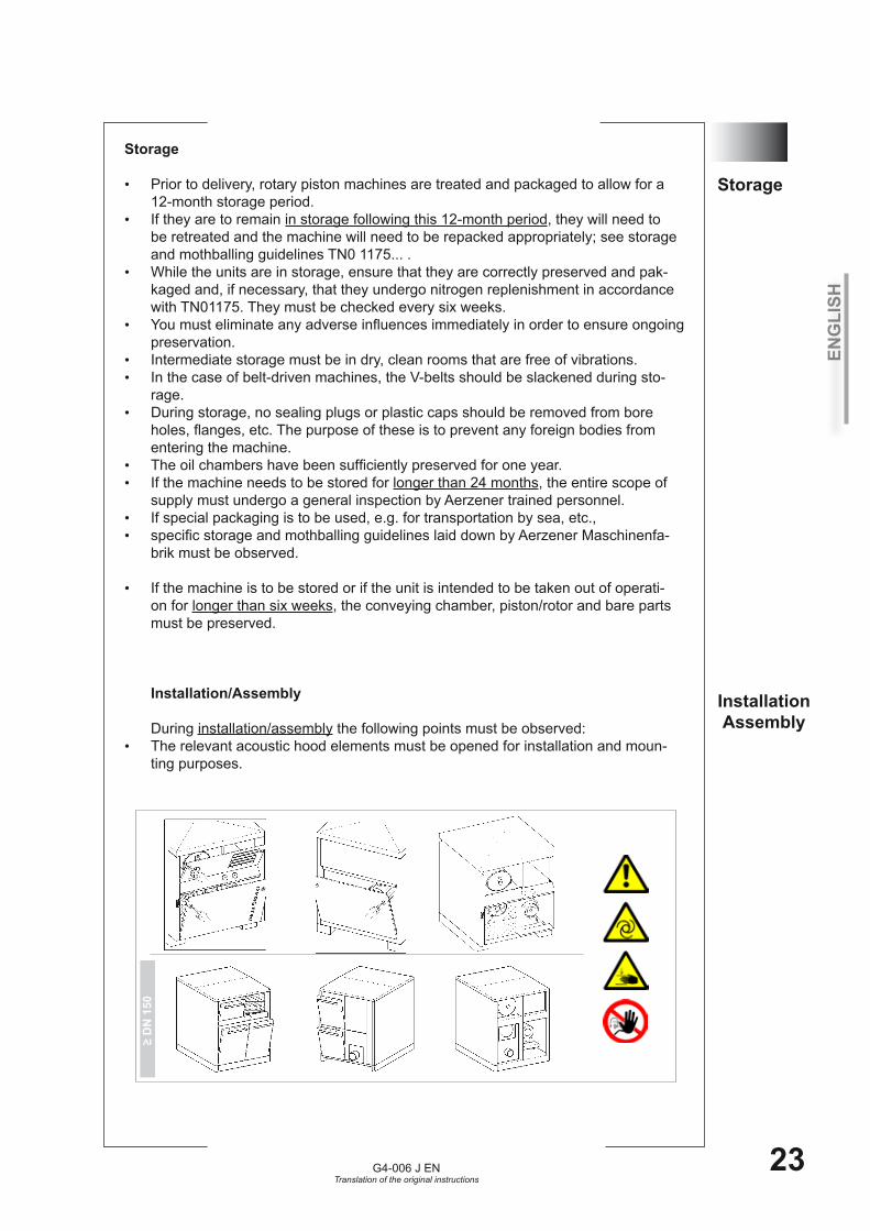
Prior to delivery, rotary piston machines are treated and packaged to allow for a •12-month storage period. If they are to remain • in storage following this 12-month period, they will need to be retreated and the machine will need to be repacked appropriately; see storage and mothballing guidelines TN0 1175... .While the units are in storage, ensure that they are correctly preserved and pak-•kaged and, if necessary, that they undergo nitrogen replenishment in accordance with TN01175. They must be checked every six weeks.You must eliminate any adverse influences immediately in order to ensure ongoing •preservation.Intermediate storage must be in dry, clean rooms that are free of vibrations. •In the case of belt-driven machines, the V-belts should be slackened during sto-•rage.During storage, no sealing plugs or plastic caps should be removed from bore •holes, flanges, etc. The purpose of these is to prevent any foreign bodies from entering the machine.The oil chambers have been sufficiently preserved for one year.•If the machine needs to be stored for • longer than 24 months, the entire scope of supply must undergo a general inspection by Aerzener trained personnel.If special packaging is to be used, e.g. for transportation by sea, etc., •specific storage and mothballing guidelines laid down by Aerzener Maschinenfa-•brik must be observed.
If the machine is to be stored or if the unit is intended to be taken out of operati-•on for longer than six weeks, the conveying chamber, piston/rotor and bare parts must be preserved. Installation/Assembly During installation/assembly the following points must be observed:The relevant acoustic hood elements must be opened for installation and moun-•ting purposes.
≥ D
N 1
50
Storage
InstallationAssembly
ENG
LISH
G4-006 J ENTranslation of the original instructions
24
5 Required ground propertiesThe unit must be installed on a stable, even foundation that does not vibrate or •incline. It is • not permitted to monitor the unit hollow or on lamellar foundations. Risk of deformation of the acoustic hood substructure!The foundation, e.g. cement floor, should have a recommended surface pressure •resistance of 30 - 40 N/mm2.
The following foundation tolerances must be observed: •
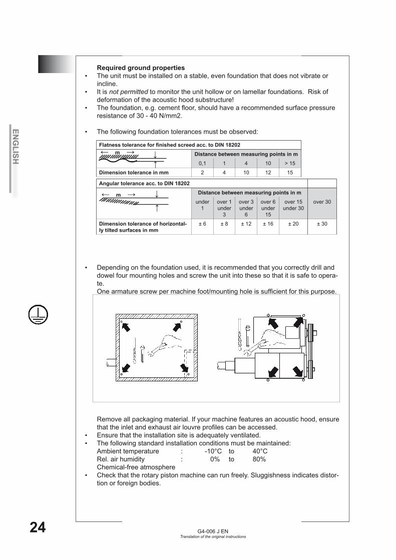
Depending on the foundation used, it is recommended that you correctly drill and •dowel four mounting holes and screw the unit into these so that it is safe to opera-te.One armature screw per machine foot/mounting hole is sufficient for this purpose. Remove all packaging material. If your machine features an acoustic hood, ensure that the inlet and exhaust air louvre profiles can be accessed.Ensure that the installation site is adequately ventilated.•The following standard installation conditions must be maintained: •Ambient temperature : -10°C to 40°C Rel. air humidity : 0% to 80% Chemical-free atmosphereCheck that the rotary piston machine can run freely. Sluggishness indicates distor-•tion or foreign bodies.
← m →Flatness tolerance for finished screed acc. to DIN 18202
Distance between measuring points in m0,1 1 4 10 > 15
Dimension tolerance in mm 2 4 10 12 15
↓
↓
Angular tolerance acc. to DIN 18202Distance between measuring points in m
under 1
over 1 under
3
over 3under
6
over 6under
15
over 15under 30
over 30
Dimension tolerance of horizontal-ly tilted surfaces in mm
± 6 ± 8 ± 12 ± 16 ± 20 ± 30
↓
↓
← m →
ENG
LISH
G4-006 J ENTranslation of the original instructions
25
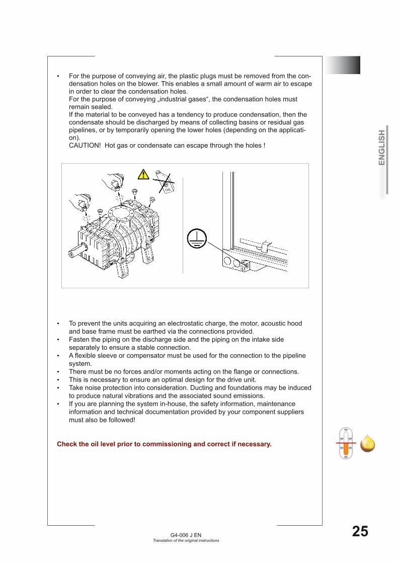
5For the purpose of conveying air, the plastic plugs must be removed from the con-•densation holes on the blower. This enables a small amount of warm air to escape in order to clear the condensation holes.For the purpose of conveying „industrial gases“, the condensation holes must remain sealed.If the material to be conveyed has a tendency to produce condensation, then the condensate should be discharged by means of collecting basins or residual gas pipelines, or by temporarily opening the lower holes (depending on the applicati-on).CAUTION! Hot gas or condensate can escape through the holes !
To prevent the units acquiring an electrostatic charge, the motor, acoustic hood •and base frame must be earthed via the connections provided.Fasten the piping on the discharge side and the piping on the intake side •separately to ensure a stable connection. A flexible sleeve or compensator must be used for the connection to the pipeline •system.There must be no forces and/or moments acting on the flange or connections.•This is necessary to ensure an optimal design for the drive unit.•Take noise protection into consideration. Ducting and foundations may be induced •to produce natural vibrations and the associated sound emissions.If you are planning the system in-house, the safety information, maintenance •information and technical documentation provided by your component suppliers must also be followed!
Check the oil level prior to commissioning and correct if necessary.
ENG
LISH
G4-006 J ENTranslation of the original instructions
26
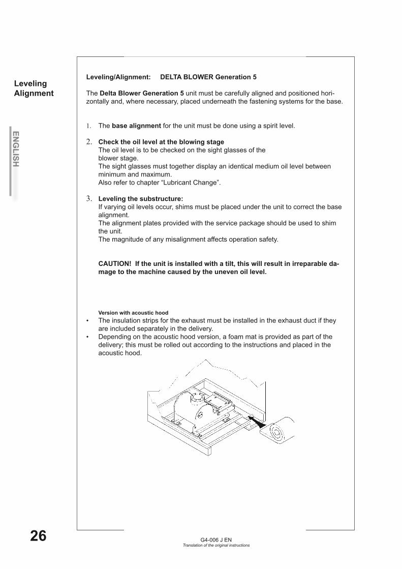
Leveling/Alignment: DELTA BLOWER Generation 5 The Delta Blower Generation 5 unit must be carefully aligned and positioned hori-zontally and, where necessary, placed underneath the fastening systems for the base.
The 1. base alignment for the unit must be done using a spirit level.
Check the oil level at the blowing stage 2.The oil level is to be checked on the sight glasses of the blower stage. The sight glasses must together display an identical medium oil level between minimum and maximum. Also refer to chapter “Lubricant Change”.
Leveling the substructure:3. If varying oil levels occur, shims must be placed under the unit to correct the base alignment. The alignment plates provided with the service package should be used to shim the unit.The magnitude of any misalignment affects operation safety. CAUTION! If the unit is installed with a tilt, this will result in irreparable da-mage to the machine caused by the uneven oil level. Version with acoustic hoodThe insulation strips for the exhaust must be installed in the exhaust duct if they •are included separately in the delivery.Depending on the acoustic hood version, a foam mat is provided as part of the •delivery; this must be rolled out according to the instructions and placed in the acoustic hood.
LevelingAlignment
ENG
LISH
G4-006 J ENTranslation of the original instructions
27
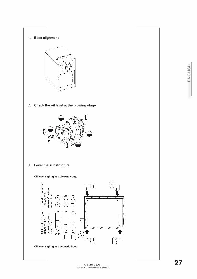
Base alignment1.
Check the oil level at the blowing stage 2.
Level the substructure 3. Oil level sight glass blowing stage Oil level sight glass acoustic hood
ENG
LISH
G4-006 J ENTranslation of the original instructions
28
6 Driving motor
Observe the Aerzen operating instructions when using driving motors with an Aerzen type plate.
Motor connection
Connect and operate the driving motor in accordance with the manufacturer‘s •operating and connection instructions. Electric motor connection: Refer to the type plate, the inside of the terminal box or •the information attached to the motor housing for technical data relating to the mo-tor. Observe the motor operating manual, supplied separately. You must ensure that the nominal electrical data is complied with during operation.•Only authorised electrical fitters may perform the connection. •Observe the tightening torques of the terminal screws.•Install connecting cables for the electric motor so that the cables cannot be •damaged. The small movements of the hinged motor support must be taken into account for the belt-driven version. The following instructions must be observed: Motor cable installation for belt-driven units. Generation 5: If your unit has an acoustic hood, it may be necessary to remove •the intake console and the acoustic hood cover to connect the motor, depending on the size and output of the unit.Electricians must observe all applicable regulations when connecting the motor.•EN 60204-1 must be observed.•Secure all connections against accidental loosening.•The connecting hardware must be suitable for the cross-section and type of the •connecting leads.Cables, leads and connections must not be subjected to excessive bending and •tensile forces.Install the connecting cables via a stayed cable bridge to prevent the terminal box •being subjected to forces or stress.Install cables and leads in such a way that they cannot sustain any external dam-•age. Avoid contact with the machine, excessive friction and excessive radiant heat.•The cable and lead sheathing must be resistant to normal wear which is to be •expected due to the movement of the hinged motor mounting plate and the effects of contaminants in the atmosphere.Fine-core cable is recommended for the connecting leads.•Connect the motor and control circuit voltage to a common, stable network to •ensure that the locking of the power contactor will be disabled if the power supply fails. Avoid voltage fluctuations and dips.Prerequisites for operating positive displacement machines with electric induction •motors in a three-phase AC supply system: Only use the machine in a stable three-phase supply system. Observe the voltage and frequency limits specified in EN 60034-1. Voltage fluctuations/dips beyond the accepted tolerances can lead to serious dam-age to all drive system elements, such as couplings, V-belts, V-belt pulleys, shafts, gear wheels, etc. If excessive voltage fluctuations arise in the system, Aerzener Maschinenfabrik recommends the following in order to prevent the blower, compressor or motor from sustaining damage: - Use suitable protective equipment that will shut the motor down and safeguard it against an automatic restart if impermissible operating data is detected. Observe also EN 60034-1 and EN 60 204-1.

ENG
LISH
G4-006 J ENTranslation of the original instructions
29
6
Motor assembly performed by the customer
If the motor is to be assembled by the customer, sufficient motor cooling must be •ensured.Observe the specifications and paperwork provided by the motor manufacturer.•Observe and comply with the centre distances and clearances to the positive dis-•placement machine specified by Aerzener Maschinenfabrik.Observe the maximum permissible motor weight.•Install and align the motor in line with the drive. •Place shims underneath the motor, if necessary. The magnitude of any misalign-ment affects the service life of the drive elements.
Permissible starting frequencies of the driving motors
Up to 160 kW = 6 starts per hour•From 200 kW = 3 cold starts or 2 warm starts per hour•Refer to the paperwork provided by the motor manufacturer for further specifica-•tions and information.
VDE 0298
Kabel Kunststoffkabelcable plastic-instulated cable
Uo = 0,6 kV Uo > 0,6 kV
einadrig 15 x d 15 x dsingle core
mehradrig 12 x d 15 x dmulti core
ENG
LISH
G4-006 J ENTranslation of the original instructions
30
7 Commissioning1. The blower unit is to be set up and installed in accordance with these instructions.
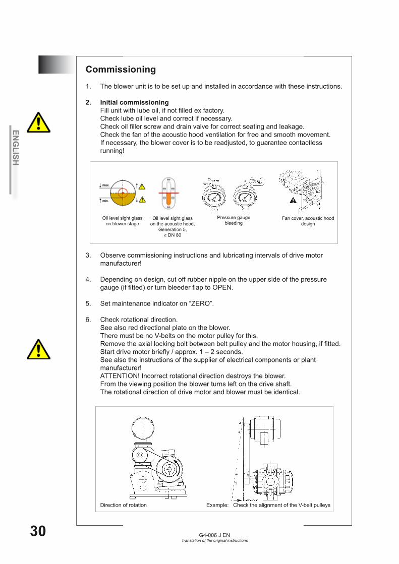
2. Initial commissioning Fill unit with lube oil, if not filled ex factory. Check lube oil level and correct if necessary. Check oil filler screw and drain valve for correct seating and leakage. Check the fan of the acoustic hood ventilation for free and smooth movement. If necessary, the blower cover is to be readjusted, to guarantee contactless running! 3. Observe commissioning instructions and lubricating intervals of drive motor manufacturer!
4. Depending on design, cut off rubber nipple on the upper side of the pressure gauge (if fitted) or turn bleeder flap to OPEN.
5. Set maintenance indicator on “ZERO”.
6. Check rotational direction. See also red directional plate on the blower. There must be no V-belts on the motor pulley for this. Remove the axial locking bolt between belt pulley and the motor housing, if fitted. Start drive motor briefly / approx. 1 – 2 seconds. See also the instructions of the supplier of electrical components or plant manufacturer! ATTENTION! Incorrect rotational direction destroys the blower. From the viewing position the blower turns left on the drive shaft. The rotational direction of drive motor and blower must be identical.
Direction of rotation Example: Check the alignment of the V-belt pulleys
Oil level sight glass on blower stage
Oil level sight glass on the acoustic hood,
Generation 5, ≥ DN 80
Fan cover, acoustic hood design
Pressure gauge bleeding
ENG
LISH
G4-006 J ENTranslation of the original instructions
31
77. When rotational direction is correct: Remove the transport securing bolt on the hinged motor support plate. Check the alignment of the belt pulleys. Lift the hinged motor support plate with the aid of a hydraulic lifter. Install the V-belts. Relieve the hinged motor support plate / remove the hydraulic lifter. The weight of the motor automatically tensions the V-belts. Close the openings on the motor drive shaft in the belt guard with the pre-i nstalled, adjustable protective covers. Push the protective covers up to a maximum of 10 mm toward the motor drive shaft and secure.
8. Connect the pipes to the operational unit.
9. Labels with safety instructions must be legible and safety devices tested.
10. Open valves on the system side. The machine can be started.
11. Switch on drive motor! Switch off after approx. 20 seconds and monitor blower for ease of run-down. If the pressure relief valve blows, shut the system down immediately and remove the cause.
12. Switch on again. Check EMERGENCY-OFF button!
13. The unit is now ready for operation.
ENG
LISH
G4-006 J ENTranslation of the original instructions
32
8 Switch off / shutdown
Switch off is effected via the power switch on the motor.•To shut the unit down completely the fuses must be removed after the blower has •come to a standstill. The valves on the conveying pipes must be closed. Avoid possible entry of condensate into the blower stage.In case of a shutdown for more than six weeks the conveying chamber is to be •preserved and the blower turned regularly by hand to avoid damage due to stand-still. Observe also the TN01175 regulations governing storage and preservation.
In case of danger:Press EMERGENCY - OFF button. For details refer to the instructions of the supplier of electrical components or the plant manufacturer.

ENG
LISH
G4-006 J ENTranslation of the original instructions
33
9Frequency converter operationIf the electric motor is driven by frequency converters, we strongly recommend •using an engine throttle and power choke. These are specifically designed for the frequency converter and filter dangerous harmonics from the drive current. Damage to the motor winding can be prevented by improving the electromagnetic compatability of the system and reducing reactions of the frequency converter in the current.The electrical and mechanical characteristics of the drive motor are to be taken •into account.The minimum frequency must always be fixed. This frequency must never fall •below the fixed minimum during operation. The maximum frequency is to be set by taking into account the maximum rotatio-•nal speed of the motor and the maximum speed of the blower / compressor. The run-up time of the drive motor from standstill up to minimum speed may be 3 •to 6 seconds. The frequency converter must be designed with a constant load moment for ope-•ration with a working machine.Rotational speeds must no fall below minimum nor exceed maximum. •The highest admissible voltage increase speed of the motor converter is 1200 V/•µs. When exceeding the value, e.g. due to excessively long cables, frequency conver-•ter type… etc. a motor throttle / motor filter coil to match the frequency converter is to be used. If these components are not used, this can lead to damage of the motor isolation •and to a motor breakdown. The maximum rotational changeover speed on positive displacement blowers / •screw compressors, after run-up to minimum speed, amounts to 1 Hz per second for upward and downward control time. Minimum frequency = 20 Hz // maximum frequency = 50 Hz results in a control •time of 30 seconds from minimum to maximum. The maximum current limit of the motor must not be exceeded. Observe the soeci-•ficationa on the motor name plate. To prevent operational faults the function “Interception circuit” must not be para-•meterised in the control of the frequency converter. When the frequency converter is switched off, a restart should only be possible after a complete standstill of the blower or compressor. Only applies to screw compressorsAt a speeds below 50% the oil pressure sinks to approximately 0.6 bar (ü). To •enable the machine to run at speeds up to 25% the ain oil pressure switch, setting value of 1.8 bar (ü), is bridged with a threshold switch. A further switch, setting value of 0.5 bar (ü), is installed for oil pressure safety.
Operation with pole-changing motorBetween a changeover of motor speed
from a high to a low speed, the motor must have reached zero rotational speed •each time. from a low to a high speed, changeover can take place instantaneously. •
ENG
LISH
G4-006 J ENTranslation of the original instructions
34
10 Maintenance
Maintenance is to ensure that all functions are maintained or that they can be restored after a breakdown.
Maintenance includes specifications about inspection, service and repairs.
Maintenance includes instructions for trained and qualified personnel.
If anything is unclear consult Aerzener customer service.
During inquiries please state: order and serial number•prevailing faults / malfunctions as accurately as possible•steps taken to rectify faults.•
Is the machine sent back to the supplier, the following measures are to be carried out: Completely drain oil, otherwise it is transport of hazardous goods.•Treat bare components with preservative.•Seal flange with blind cover.•Seal open connections.•Also observe instructions in chapter “Transport”.•
Inspections / inspection schedule
A general inspection should be carried out by a service technician from Aerzener after 3 years or 20,000 operating hours. This includes the preventive maintenance of wearing and replacement parts such as bearings, seal, etc.We recommend maintaining a stock of replacement and wearing parts to avoid or reduce waiting times and downtimes.
10.1

ENG
LISH
G4-006 J ENTranslation of the original instructions
35
10.2
Whenever carrying out work on the positive displacement machine, it must be switched off and disconnected from the supply net! This is to avoid the risk of injury and damage to the equipment! To guarantee long service life and optimum operating conditions, the maintenance work listed in the following table must be carried out at the specified intervals.
Maintenance intervals
We recommend carrying out maintenance on the blower at the intervals specified below. The ope-rating hours refer to normal operating conditions. Other intervals could apply depending on operating specifications and environmental conditions. In this case please consult Aerzener Maschinenfabrik. A
fter t
he fi
rst
3 O
h
Afte
r the
firs
t25
Oh
Wee
kly
Afte
r the
firs
t50
0 O
h
Afte
r eve
ry 1
000
Oh
Hal
f-yea
rly in
cle
an
envi
ronm
ent
-mon
thly
in d
usty
en
viro
nmen
t
Afte
r eve
ry 4
000
Oh
or h
alf-y
early
Afte
r eve
ry 8
000
Oh
Or y
early
Afte
r eve
ry 2
0,00
0 O
hO
r afte
r 3 y
ears
Retaining screws and fittingsretighten after machine has cooled• ●
Starting strainer, if installedcheck, if no more contaminant it can be removed• ●
Intake filtercheck filter for contamination, replace if necessary, •max. -45 barreplace filter insert•
●
●Air intake / air exhaust openings
of acoustic hood, check and clean• ●Condition of V-belt
check, replace if necessary• ● ● ● ●V-belt pulley alignment
check, correct if necessary• ● ● ● ● ●Pressure valve
check function• ● ●Oil level
check• ● ● ●Lubricating oil
exchange•* 5W-40, at end temperatures above 140°C•
●*●
●
Grease, only for gas-tight shaft sealexchange•*at end temperatures above 140°C, 5W-40•
●*●
●
Non-return valvecheck for wear and leakage• ●
Main inspection / maintenancecheck / replace wearing parts•overall check of machine• ●
Drive motorcarry out maintenance•observe grease replacement intervals•
Please observe maintenance intervals and specifications of motor manufacturer!In case of Aerzener motors observe Aezerner operating and maintenance instruc-
tions!
Have the positive displacement machine checked by Aerzener service at the specified intervals or yearly at the latest.Or: Take out a maintenance contract with Aerzener Maschinenfabrik.
Through regular and proper maintenance Aerzener Machinenfabrik guarantees maximum safety for your operation.
Maintenance schedule

ENG
LISH
G4-006 J ENTranslation of the original instructions
36
10.3 Lubricating oil specification for rotary piston blowersAdditives and viscosity class are the defining factors in selecting types of lubricating oil. The following oils, which are of the correct viscosity and contain appropriate additives, are to be used in accordance with the relevant operating conditions.
1. General requirements for lubricating oil propertiesKinematic viscosity at operating oil temperature : 10 - 13 cSt (mm2/s)Kinematic viscosity at -10°C : ≤ 3500 cSt (mm2/s)
Minimum oil additive properties EP wearing protection additives for use in roller bearing gearboxes•Oxidation stability up to 110°C oil sump temperature, •at continuous oil temperatures above 120°C = oxidation stability up to 220°C oil sump temperatureFoam suppressor•Detergents for solution of deposits•Neutrality compared with sealing materials made of fluoro-propylene-methyl (Vi-•ton).Neutrality compared with single-component resin primers•Adequate shear stability •
* Ambient temperature = Temperature in the immediate environment of the machine all year round.
2. Single or double-shift operation / intermittent operation Intake temperature stage : Up to 50°C Final compression temperature : Up to 140°C Ambient temperature* : No restriction Lubricant to be used : Aerzener special rotary piston oil, Order no.: 160 754 or 160 755This lubricating oil is used for the initial filling for standard application conditions.
3. Continuous operation / 24 hours per day Intake temperature stage : Up to 50°C Final compression temperature : Up to 140°C Ambient temperature* : No restriction Lubricant to be used : Aerzener special rotary piston oil, Order no.: 160 754 or 160 755 or ISO VG 150 Fully synthetic (PAO) poly-alpha-olefin, gearbox or compressor oil Example : MOBIL SHC 629
ENG
LISH
G4-006 J ENTranslation of the original instructions
37
10.34. Operation at final compression temperatures above 140°C Continuous oil temperature : 120°C to 140°C or Final compression temperature : Above 140°C Lubricant to be used : ISO VG 220 Synthetic lubricating oil with a polyglycol base oil. Example: ESSO Glycolube 220 ARAL Degol GS 220 Note : Oil change intervals are to be halved in case of significant, dark oil discolouration.
5. Lubricating oils in the foodstuffs and pharmaceutical industry For rotary piston blowers it is possible to use lubricating oils that have approval as per the specification USDA H1.Experience in operation is only available with the following lubricating oil. Aerzener Maschinenfabrik cannot approve any other oils. It is recommended to perform an oil analysis in agreement with the oil manufacturer after 1000 operating hours.
Final compression temperature : Up to 120°C Continuous oil temperature : Up to 100°C Lubricant to be used : ISO VG 100 Klüber oil 4UH1-100 N
Final compression temperature : Above 120°C Continuous oil temperature : Above 100°C Lubricant to be used : ISO VG 220 Klüber oil 4UH1-220 N
Changing to other oil typesThe Aerzener special rotary piston oil and PAO oils are completely consolute. •When switching from one type of oil to another, there are no special measures to be taken into account. However, in order to maintain the useful properties of the new oil type, the oil to be changed should be completely drained and a single intermediate oil change undertaken after an operating period of 100 hours. Only the same oil should be used for refilling.Polyglycol-based oils cannot be mixed with Aerzener special rotary piston oil or •PAO oils. In case of doubt, the oil chambers are to be opened and flushed.Oils based on perfluorinated polyethers, e.g. Fomblin, cannot be mixed with either •Aerzener special rotary piston oil or with PAO, or with polyglycol oils. To change the oil the machine must be completely dismantled and the entire oil system through cleaned of all residue. A flushing run prior to commissioning is recom-mended.
ENG
LISH
G4-006 J ENTranslation of the original instructions
38
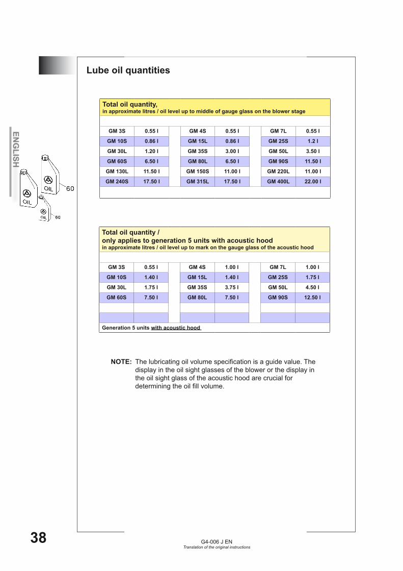
10.4 Lube oil quantities
Total oil quantity, in approximate litres / oil level up to middle of gauge glass on the blower stage
GM 3S 0.55 l GM 4S 0.55 l GM 7L 0.55 l
GM 10S 0.86 l GM 15L 0.86 l GM 25S 1.2 l
GM 30L 1.20 l GM 35S 3.00 l GM 50L 3.50 l
GM 60S 6.50 l GM 80L 6.50 l GM 90S 11.50 l
GM 130L 11.50 l GM 150S 11.00 l GM 220L 11.00 l
GM 240S 17.50 l GM 315L 17.50 l GM 400L 22.00 l
Total oil quantity / only applies to generation 5 units with acoustic hood in approximate litres / oil level up to mark on the gauge glass of the acoustic hood
GM 3S 0.55 l GM 4S 1.00 l GM 7L 1.00 l
GM 10S 1.40 l GM 15L 1.40 l GM 25S 1.75 l
GM 30L 1.75 l GM 35S 3.75 l GM 50L 4.50 l
GM 60S 7.50 l GM 80L 7.50 l GM 90S 12.50 l
Generation 5 units with acoustic hood
NOTE: The lubricating oil volume specification is a guide value. The display in the oil sight glasses of the blower or the display in the oil sight glass of the acoustic hood are crucial for determining the oil fill volume.
ENG
LISH
G4-006 J ENTranslation of the original instructions
39
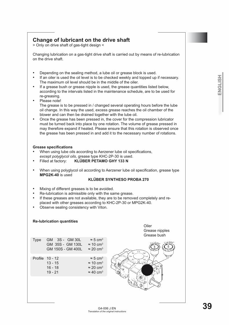
Change of lubricant on the drive shaft> Only on drive shaft of gas-tight design <
Changing lubrication on a gas-tight drive shaft is carried out by means of re-lubrication on the drive shaft.
Depending on the sealing method, a lube oil or grease block is used.•If an oiler is used the oil level is to be checked weekly and topped up if necessary.•The maximum oil level should be in the middle of the oiler.If a grease bush or grease nipple is used, the grease quantities listed below, •according to the intervals listed in the maintenance schedule, are to be used for re-greasing.Please note! •The grease is to be pressed in / changed several operating hours before the lube oil change. In this way the used, excess grease reaches the oil chamber of the blower and can then be drained together with the lube oil.Once the grease has been pressed in, the cover for the compression lubricator •must be turned back into place by one rotation. The volume of grease pressed in may therefore expand if heated. Please ensure that this rotation is observed once the grease has been pressed in and add it to the necessary number of rotations.
Grease specifications When using lube oils according to Aerzener lube oil specifications, •except polyglycol oils, grease type KHC-2P-30 is used. Filled at factory: • KLÜBER PETAMO GHY 133 N
When using polyglycol oil according to Aerzener lube oil specification, grease type •MPG2K-40 is used KLÜBER SYNTHESO PROBA 270
Mixing of different greases is to be avoided.•Re-lubrication is admissible only with the same grease.•If these greases are not available, they are to be removed completely and re-•placed with other greases according to KHC-2P-30 or MPG2K-40.Observe sealing consistency with Viton. •
Re-lubrication quantities Oiler Grease nipples Grease bushType GM 3S - GM 30L ≈ 5 cm3
GM 35S - GM 130L ≈ 10 cm3
GM 150S - GM 400L ≈ 20 cm3
Profile 10 - 12 ≈ 5 cm3
13 - 15 ≈ 10 cm3
16 - 18 ≈ 20 cm3
19 - 21 ≈ 40 cm3
10.5
ENG
LISH
G4-006 J ENTranslation of the original instructions
40
10.6 Changing lubricant
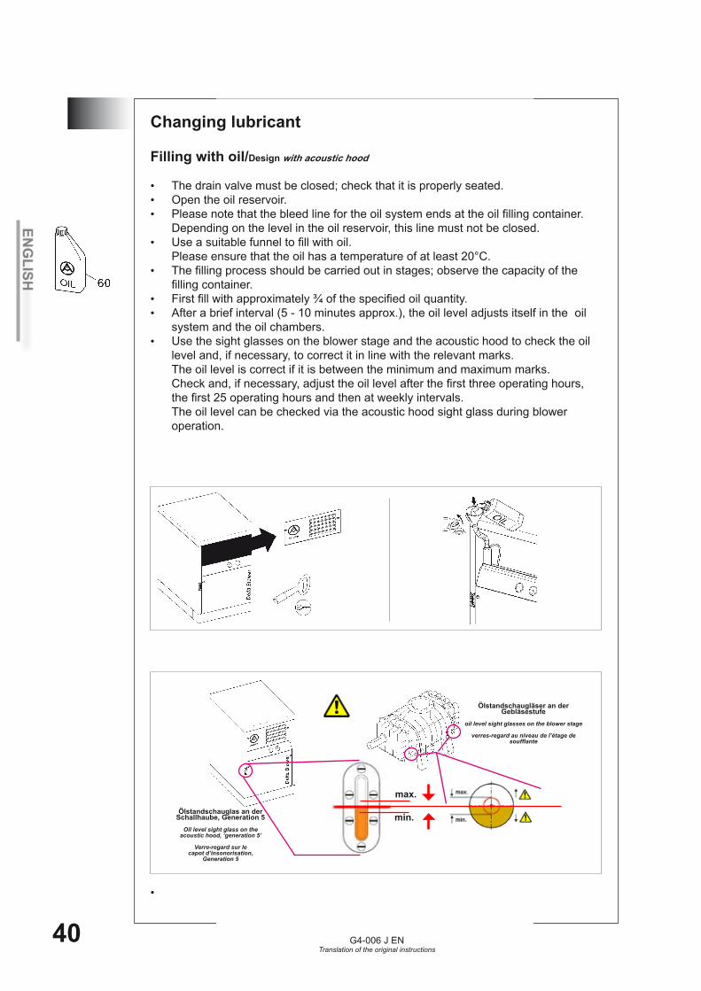
Filling with oil/Design with acoustic hood
The drain valve must be closed; check that it is properly seated.•Open the oil reservoir.•Please note that the bleed line for the oil system ends at the oil filling container. •Depending on the level in the oil reservoir, this line must not be closed.Use a suitable funnel to fill with oil. •Please ensure that the oil has a temperature of at least 20°C.The filling process should be carried out in stages; observe the capacity of the •filling container.First fill with approximately ¾ of the specified oil quantity. •After a brief interval (5 - 10 minutes approx.), the oil level adjusts itself in the oil •system and the oil chambers.Use the sight glasses on the blower stage and the acoustic hood to check the oil •level and, if necessary, to correct it in line with the relevant marks. The oil level is correct if it is between the minimum and maximum marks. Check and, if necessary, adjust the oil level after the first three operating hours, the first 25 operating hours and then at weekly intervals. The oil level can be checked via the acoustic hood sight glass during blower operation.
•
Ölstandschaugläser an der Gebläsestufe
oil level sight glasses on the blower stage
verres-regard au niveau de l’étage de soufflante
Ölstandschauglas an der Schallhaube, Generation 5
Oil level sight glass on the acoustic hood, ‘generation 5’
Verre-regard sur le capot d’insonorisation,
Generation 5
max.
min.
ENG
LISH
G4-006 J ENTranslation of the original instructions
41
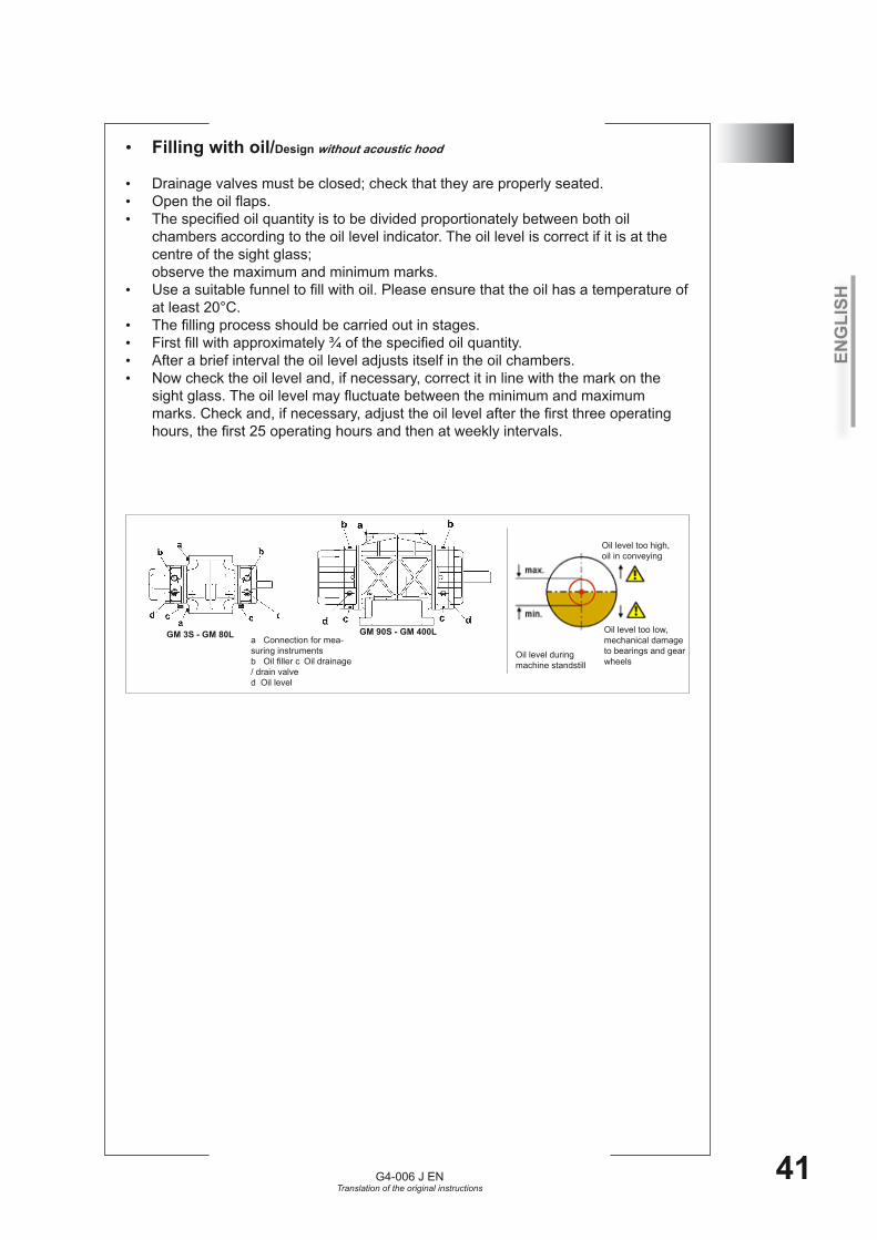
10.6Filling with oil• /Design without acoustic hood
Drainage valves must be closed; check that they are properly seated.•Open the oil flaps.•The specified oil quantity is to be divided proportionately between both oil •chambers according to the oil level indicator. The oil level is correct if it is at the centre of the sight glass; observe the maximum and minimum marks.Use a suitable funnel to fill with oil. Please ensure that the oil has a temperature of •at least 20°C.The filling process should be carried out in stages. •First fill with approximately ¾ of the specified oil quantity. •After a brief interval the oil level adjusts itself in the oil chambers.•Now check the oil level and, if necessary, correct it in line with the mark on the •sight glass. The oil level may fluctuate between the minimum and maximum marks. Check and, if necessary, adjust the oil level after the first three operating hours, the first 25 operating hours and then at weekly intervals.
GM 3S - GM 80L GM 90S - GM 400La Connection for mea-suring instrumentsb Oil filler c Oil drainage / drain valve d Oil level
Oil level during machine standstill
Oil level too high, oil in conveying
Oil level too low, mechanical damage to bearings and gear wheels
ENG
LISH
G4-006 J ENTranslation of the original instructions
42
10.6 Draining oil
The initial operating oil container can be used as a catch pan. The waste oil can be properly collected in this container and disposed of in an environmentally-friendly manner at an appropriate collecting station. Please observe the container‘s capacity.
a) b) Screw the cap (1) and threaded plug (1) off the drain valve. If the cap (1) and threaded plug (1) are too tight, hold the valve tightly with an open-jaw wrench and loosen position (1) with a second wrench.a) Screw on the hose supplied.a) The drain valve opens automatically.a) Position the end of the hose in a catch pan. b) Open the manual valve; drain the waste oil into a container.a) b) Dispose of waste oil properly.a) Remove the hose from the drain valve. b) Close the manual valve; screw the threaded plug (1) in whilst holding the valve tight.a) Screw the cap (1) onto the drain valve until it is hand-tight.a) b) If the entire drain valve becomes loose or detached from the thread, it must be replaced by a new valve and seal.
Please observe the oil temperature when changing the oil. The oil temperature must not exceed 60°C, due to the thermal load capacity of the „drain hose“. If the oil temperature is above 60°C, there is a risk of burns.

ENG
LISH
G4-006 J ENTranslation of the original instructions
43
10.6
Design with acoustic hood c - Oil drainage / drain valve
Beispiel / example a)
Design without acoustic hoodc - Oil drainage / drain valve
Beispiel / example a) b)

ENG
LISH
G4-006 J ENTranslation of the original instructions
44
10.7 V-belt installation / replacement For all work necessary on the belt drive, the machine is to be taken out of operati on and properly disconnected from the supply. Starting / operation of the machine must be excluded. Caution: On the belt drive and hinged motor plate there is the risk of shea ring and squashing!
Open belt protection housing and / or acoustic hood. •Disassemble protective cover on compressor or blower belt pulley, only in case of •design without acoustic hood.Disassemble protective cover / plastic plate on motor belt pulley, only in case of •design with acoustic hood.When installing the V-belts for the first time, remove the transport locking screws •or the transport locking bracket.Depending on machine size, the hinged motor plate is to be lifted by hand or by •means of the supplied hydraulic jack kit until the belts can be installed or ex-changed. When replacing the V-belt on units with acoustic hoods the cover plate for the fan •is to be removed.During lifting of the hinged motor plate it is to be supported stage by stage, in •order to avoid possible accidents.In the case of designs with a transportation safety rod, when lifting the hinged •motor support the rod must be placed in the groove on the base support. The rod acts as a limit stop for the hinged motor support. The hydraulic jack can therefore be placed underneath in order to raise the hinged support. The V-belts are to be replaced as a set.•The hinged motor plate is to be completely lowered.•The belt drive is automatically tensioned by the motor weight.•Belt guard, cover plate for the fan and the protective covers are to be properly •installed and / or the acoustic cover to be closed.In case of design with protective belt housing the distance between motor drive •shaft and plastic cover is maximum 10 mm.
Lifting of various hinged motor support plates ATTENTION! Chock hinged motor support plate during lifting.
Disassembly drawing of various transport brackets
Motor shaft cover Fan cover
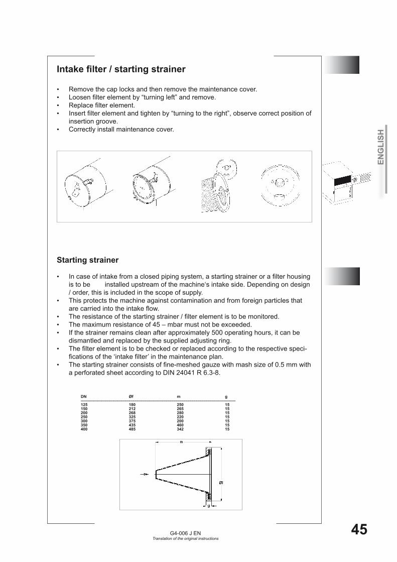
ENG
LISH
G4-006 J ENTranslation of the original instructions
45
10.8Intake filter / starting strainer
Remove the cap locks and then remove the maintenance cover.•Loosen filter element by “turning left” and remove.•Replace filter element.•Insert filter element and tighten by “turning to the right”, observe correct position of •insertion groove.Correctly install maintenance cover.•
10.9Starting strainer
In case of intake from a closed piping system, a starting strainer or a filter housing •is to be installed upstream of the machine‘s intake side. Depending on design / order, this is included in the scope of supply. This protects the machine against contamination and from foreign particles that •are carried into the intake flow. The resistance of the starting strainer / filter element is to be monitored.•The maximum resistance of 45 – mbar must not be exceeded.•If the strainer remains clean after approximately 500 operating hours, it can be •dismantled and replaced by the supplied adjusting ring. The filter element is to be checked or replaced according to the respective speci-•fications of the ‘intake filter’ in the maintenance plan.The starting strainer consists of fine-meshed gauze with mash size of 0.5 mm with •a perforated sheet according to DIN 24041 R 6.3-8. DN Øf m g
-------------------------------------------------------------------------------------------------------------------- 125 180 250 15 150 212 265 15 200 268 280 15 250 325 220 15 300 375 200 15 350 435 460 15 400 485 342 15

ENG
LISH
G4-006 J ENTranslation of the original instructions
46
Checking function of pressure valve
ATTENTION!
The valve is not a control component and is not to be used as such.•Observe operating instructions G4-002…for pressure valves!•The unit must be properly shut down for all work carried out on the valve.•
R2“ // DN 50 // R3“ // DN 80 // DN 125The mobility of the valve is to be checked during machine shutdown.•The valve bell is to be lifted with the aid of two screw drivers.•The valve must open correctly.•
DN 150 // DN 200 // DN 300
The mobility of the valve is to be checked during machine shutdown.•The valve is to be lifted by actuating the lever.•The valve must open correctly.• •The screwdriver is then to be removed or the aeration device is to be disengaged. •A properly functioning valve closes correctly.•The valve can be used with temperatures up to 150° C.•
10.10
DN 150 // DN 200 // DN 300R2" / R3" DN 50 // DN 80 // DN 125
ENG
LISH
G4-006 J ENTranslation of the original instructions
47
11Accessories 1. Acoustic hood for unit2. Start-up relief3. Maintenance indicator for monitoring filter contamination4. Aerzener „ASG 200“ control Please also refer to the ASG 200 operating manual.5. Thermometer for display of discharge temperature6. Pressure gauge for monitoring intake and discharge pressure7. Accessories (V-belts, intake filter, oil etc.)
In addition to the standard scope of delivery also the above-mentioned accessories can be requested from Aerzen after-sales service, where spare parts can also be ordered.The descriptions for special accessories printed in bold letters are listed as follows. The instructions of accessory manufacturers which are supplied separately are to be observed.
Accessory no. 1: acoustic hood The acoustic hood is made of powder-coated steel plate.•It is force ventilated by a fan mounted on the blower shaft.•Acoustic hoods for units up to a nominal width of 250 are generally delivered •completely assembled. For acoustic hoods in disassembled segmental design, an installation manual is available.For all work on the acoustic hood the unit is to be shut down and the drive discon-•nected from the power supply.The acoustic hood also serves as belt guard. When the unit is running the doors •are to be locked with the enclosed wrench. The locked door is then to be checked. The key is to be kept in a safe place. Only authorized persons are to have access.All maintenance work on the unit must only be carried out during machine stand-•still and after opening of the acoustic hood doors.The hinges, if installed, are to be lubricated at regular intervals in accordance with •the installation conditions.In order to protect the units from electrostatic charging, earthing cables are to be •connected at the ground straps of the base frame and the acoustic hood.Ensure that the safety labels fixed to the acoustic hood are clearly visible. •
Intake from piping Regarding the intake from piping the corresponding perforated sheets are to be •“cracked out” of the acoustic hood element, the foamed material in the diameter of the intake piping is to be cut out and removed. Feed the connection piping through the openings. Depending on design and size, adjusting plates are to be installed on the piping passage.Piping cross sections on acoustic hoods with a higher acoustic rating are to be •closed with adjusting plates.
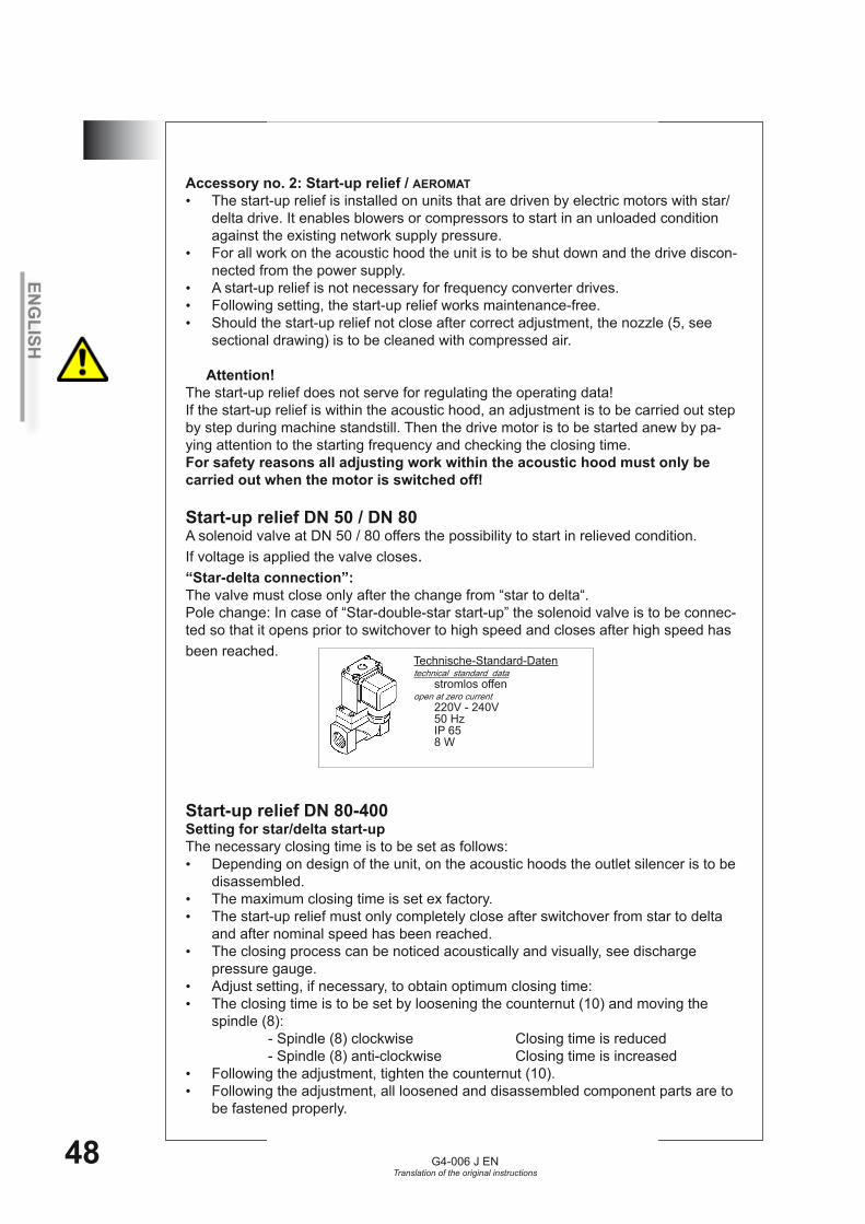
ENG
LISH
G4-006 J ENTranslation of the original instructions
48
11Accessory no. 2: Start-up relief / AEROMAT
The start-up relief is installed on units that are driven by electric motors with star/•delta drive. It enables blowers or compressors to start in an unloaded condition against the existing network supply pressure.For all work on the acoustic hood the unit is to be shut down and the drive discon-•nected from the power supply.A start-up relief is not necessary for frequency converter drives.•Following setting, the start-up relief works maintenance-free.•Should the start-up relief not close after correct adjustment, the nozzle (5, see •sectional drawing) is to be cleaned with compressed air.
Attention! The start-up relief does not serve for regulating the operating data! If the start-up relief is within the acoustic hood, an adjustment is to be carried out step by step during machine standstill. Then the drive motor is to be started anew by pa-ying attention to the starting frequency and checking the closing time.For safety reasons all adjusting work within the acoustic hood must only be carried out when the motor is switched off!
Start-up relief DN 50 / DN 80A solenoid valve at DN 50 / 80 offers the possibility to start in relieved condition.If voltage is applied the valve closes.“Star-delta connection”: The valve must close only after the change from “star to delta“.Pole change: In case of “Star-double-star start-up” the solenoid valve is to be connec-ted so that it opens prior to switchover to high speed and closes after high speed has been reached.
Start-up relief DN 80-400Setting for star/delta start-upThe necessary closing time is to be set as follows:
Depending on design of the unit, on the acoustic hoods the outlet silencer is to be •disassembled.The maximum closing time is set ex factory.•The start-up relief must only completely close after switchover from star to delta •and after nominal speed has been reached.The closing process can be noticed acoustically and visually, see discharge •pressure gauge. Adjust setting, if necessary, to obtain optimum closing time:•The closing time is to be set by loosening the counternut (10) and moving the •spindle (8): - Spindle (8) clockwise Closing time is reduced - Spindle (8) anti-clockwise Closing time is increasedFollowing the adjustment, tighten the counternut (10).•Following the adjustment, all loosened and disassembled component parts are to •be fastened properly.
Technische-Standard-Datentechnical standard data stromlos offen open at zero current 220V - 240V 50 Hz IP 65 8 W
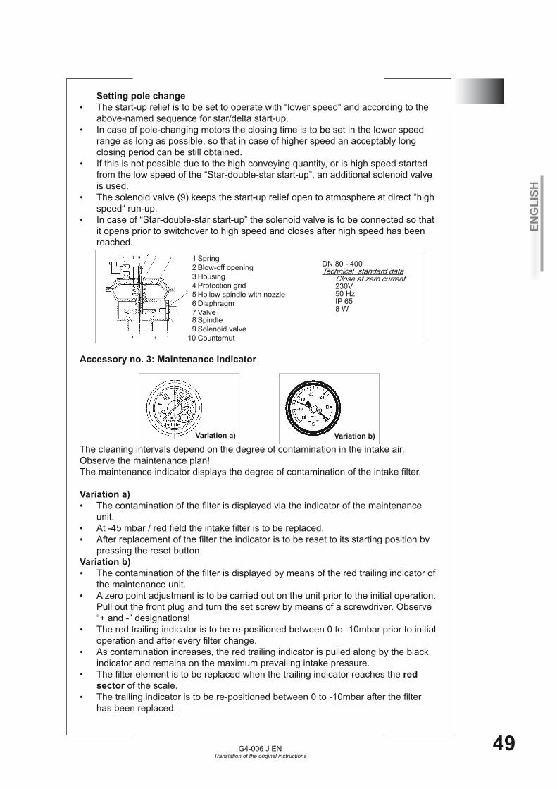
ENG
LISH
G4-006 J ENTranslation of the original instructions
49
11Setting pole change The start-up relief is to be set to operate with “lower speed“ and according to the •above-named sequence for star/delta start-up. In case of pole-changing motors the closing time is to be set in the lower speed •range as long as possible, so that in case of higher speed an acceptably long closing period can be still obtained.If this is not possible due to the high conveying quantity, or is high speed started •from the low speed of the “Star-double-star start-up”, an additional solenoid valve is used.The solenoid valve (9) keeps the start-up relief open to atmosphere at direct “high •speed“ run-up.In case of “Star-double-star start-up” the solenoid valve is to be connected so that •it opens prior to switchover to high speed and closes after high speed has been reached.
Accessory no. 3: Maintenance indicator
The cleaning intervals depend on the degree of contamination in the intake air. Observe the maintenance plan! The maintenance indicator displays the degree of contamination of the intake filter.
Variation a) The contamination of the filter is displayed via the indicator of the maintenance •unit. At -45 mbar / red field the intake filter is to be replaced.•After replacement of the filter the indicator is to be reset to its starting position by •pressing the reset button.
Variation b) The contamination of the filter is displayed by means of the red trailing indicator of •the maintenance unit.A zero point adjustment is to be carried out on the unit prior to the initial operation. •Pull out the front plug and turn the set screw by means of a screwdriver. Observe “+ and -” designations!The red trailing indicator is to be re-positioned between 0 to -10mbar prior to initial •operation and after every filter change.As contamination increases, the red trailing indicator is pulled along by the black •indicator and remains on the maximum prevailing intake pressure.The filter element is to be replaced when the trailing indicator reaches the • red sector of the scale. The trailing indicator is to be re-positioned between 0 to -10mbar after the filter •has been replaced.
Variation a)
DN 80 - 400Technical standard data Close at zero current 230V 50 Hz IP 65 8 W
1 Spring 2 Blow-off opening 3 Housing 4 Protection grid 5 Hollow spindle with nozzle 6 Diaphragm 7 Valve 8 Spindle 9 Solenoid valve 10 Counternut
Variation b)
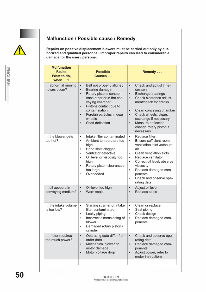
ENG
LISH
G4-006 J ENTranslation of the original instructions
50
12
MalfunctionFaults
What to do,when . . ?
Possible Causes . ..
Remedy . . .
... abnormal running noises occur?
Belt not properly aligned•Bearing damage•Rotary pistons contact •each other or in the con-veying chamberPistons contact due to •contaminationForeign particles in gear •wheels Shaft deflection•
Check and adjust if ne-•cessaryExchange bearings•Check clearance adjust-•ment/check for cracks
Clean conveying chamber•Check wheels, clean, •exchange if necessaryMeasure deflection, •change rotary piston if necessary
... the blower gets too hot?
Intake filter contaminated•Ambient temperature too •highHood slots clogged•Ventilator defective•Oil level or viscosity too •highRotary piston clearances •too largeOverloaded•
Replace filter•Ensure sufficient room •ventilation inlet-/exhaust airClean ventilation slots•Replace ventilator•Correct oil level, observe •viscosityReplace damaged com-•ponentsCheck and observe ope-•rating data
... oil appears in conveying medium?
Oil level too high•Worn seals•
Adjust oil level•Replace seals•
... the intake volume is too low?
Starting strainer or intake •filter contaminatedLeaky piping•Incorrect dimensioning of •blowerDamaged rotary piston / •cylinder
Clean or replace•Seal piping•Check design•Replace damaged com-•ponents
... motor requires too much power?
Operating data differ from •order dataMechanical blower or •motor damageMotor voltage drop•
Check and observe ope-•rating dataReplace damaged com-•ponentsAdjust power, refer to •motor instructions
Malfunction / Possible cause / Remedy
Repairs on positive displacement blowers must be carried out only by aut-horized and qualified personnel. Improper repairs can lead to considerable damage for the user / persons.

ENG
LISH
G4-006 J ENTranslation of the original instructions
51
12Malfunction
FaultsWhat to do,when . . ?
Possible Causes . ..
Remedy . . .
... the side of belt vibrates?
V-belt is worn•Belt not properly aligned•
Replace belt•Check and correct if •necessary
... the blower runs in reverse direction after shutdown?
Non-return valve defec-•tive or leaky
Replace valve •
... machine damage occurs due to faulty electrical connec-tion?
Motor and control system •are connected to two different networks
Connect motor and con-•trol voltage to one supply networkAlternative: Installation of •a power monitoring relay
After the correction of each malfunction, the following is to be checked:Freedom of movement of the machine•Non-contact turning•Lube oil level•Proper function and connection•Adherence to safety and warning instructions•

ENG
LISH
G4-006 J ENTranslation of the original instructions
52
Spare parts - overview
For effective and durable use of the rotary piston machine, there follows a list of com-ponents necessary for maintenance, an inspection or a repair.The components are grouped by expected life into three spare part versions.
1.) Maintenance Shaft sealing ring(s)•Inner ring, shaft sleeve, bush•Sealing rings and screw plugs, drain valves for oil drain•V-belt / wearing parts on coupling•Air filter element•Lubricating oil, oil filter element•
2.) Inspection Components from point 1.)•Bearing and sealing components•for compressor plus the adjustable bearing cover including the related minor items •
3.) RepairComponents from point 1.) and 2.)•Rotor pair / rotary piston pair•Timing gear wheels•for compressor plus the torsion shaft and the oil pump •
Spare parts and accessories It is specifically highlighted that original parts and accessories not supplied by us have also not been tested or approved by us. Therefore, installing or mounting and using any such products could, under certain circumstances, degrade the stipulated system characteristics. The manufacturer shall assume no liability whatsoever for damage caused by the use of non-genuine parts or accessories.
13
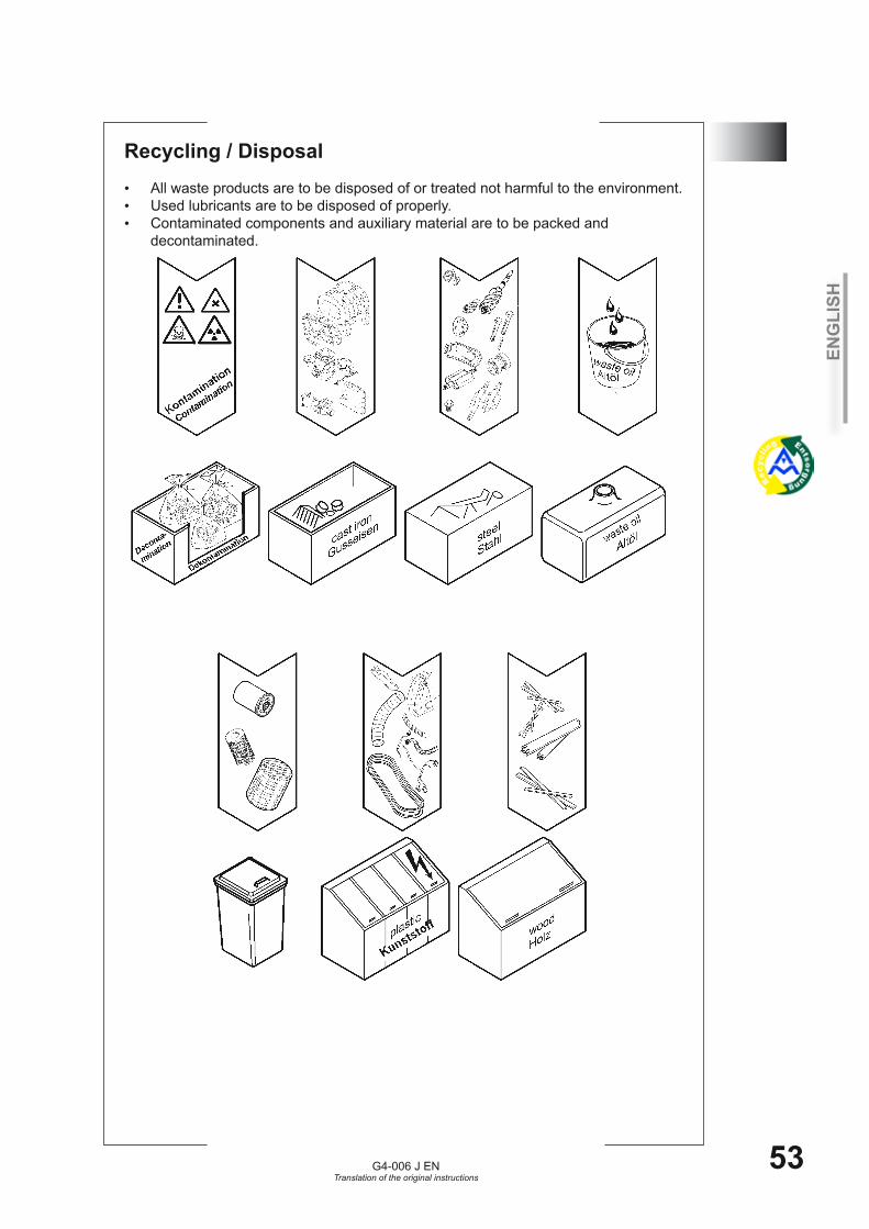
ENG
LISH
G4-006 J ENTranslation of the original instructions
53
14Recycling / DisposalAll waste products are to be disposed of or treated not harmful to the environment.•Used lubricants are to be disposed of properly.•Contaminated components and auxiliary material are to be packed and •decontaminated.
ENG
LISH
G4-006 J ENTranslation of the original instructions
54
ENG
LISH
G4-006 J ENTranslation of the original instructions
55
INFO - SEITE Information sheet Page infos Info - bladzijde PaginaInformativa
Gegenüber Darstellungen und Angaben dieser Betriebsanleitung sind technische Änderungen, die zur Verbesserung der Drehkolbenmaschinen notwendig werden, vorbehalten.
This operating- and installation manual is subject to engineering changes necessary for the compressor advancement.Nous nous réservons le droit dans les instructions de service procéder à toutes modifications techniques utiles visant à améliorer la qualité des compresseurs.
Wat de betrft de tekeningen en gegevens in deze bedienings- en opstellings-hanleiding verbetering van de schroefcompressor noodzakelijk worden, voorbehouden.Nos reservamos el derecho de efectuar, frente a las representaciones e indicaciones de esta
instrucciones de montage servicio modificaciones técnicas necesarias para perfeccionar.Rispetto all'illustrazione ed alle indicazioni di questa Istruzioni di Esercizio ci si riserva quelle modifiche tecniche che sono necessarie per migliorare i compressori.
15
06-2
009
ENG
LISH
G4-006 J ENTranslation of the original instructions
56
Aerzen im Internet
www.aerzener.com
Aerzener Maschinenfabrik GmbHReherweg 28 31855 Aerzen
Postfach 1163 31849 AerzenTelefax 0 51 54 / 81-191e-mail [email protected]
Kundenservice0 51 54 / 81-529
Aerzener International Rental B.V.www.airental.nlphone +31 (0) 26 44 64 723Telefax +31 (0) 26 44 63 570e-mail [email protected]