
MKS 647B Manual
54
Multi Channel Flow Ratio/Pressure Controller Type 647B Instruction Manual MKS Instruments Deutschland GmbH Ausgabe 11/99 Rev.11.96
-
Upload
jacob-melby -
Category
Documents
-
view
244 -
download
13
description
MKS 647B Operation and Programming Manual
Transcript of MKS 647B Manual
Multi Channel
Flow Ratio/Pressure Controller
Type 647B
Instruction Manual
MKS InstrumentsDeutschland GmbH
Ausgabe 11/99Rev.11.96
Copyright © 1999 by MKS Instrument Deutschland GmbH.
Alle Rechte vorbehalten. Es ist nicht gestattet, Teile des vorliegenden Dokuments zu vervielfältigen oder inirgendeiner Form bzw. mit irgendwelchen elektronischen oder mechanischen Mitteln, einschließlich desFotokopierens und der Aufzeichnung, bzw. mit Hilfe von Speicher- oder Informationswiedergewinnungs-systemen zu übertragen, sofern keine ausdrückliche schriftliche Genehmigung seitens der MKS InstrumentsDeutschland GmbH vorliegt.
Gedruckt in der Bundesrepublik Deutschland.
Cajon® und VCR® sind eingetragene Warenzeichen der Cajon Company, Macedonia, Ohio
Kalrez® und Viton® sind eingetragene Warenzeichen der E. I. DuPont de Nemours und Co. Inc., Wilmington,Delaware
Neoprene® ist eingetragenes Warenzeichen der Vibration, Mountings & Controls, Inc., Bloomingdale, NewJersey
Swagelok® ist eingetragenes Warenzeichen der Crawford Fitting Company, Solon, Ohio
647B Contents
iii
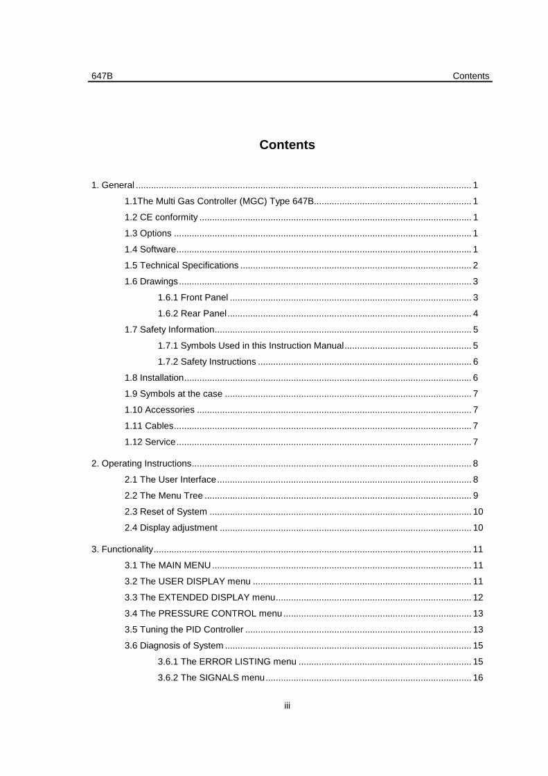
Contents
1. General .................................................................................................................................... 1
1.1The Multi Gas Controller (MGC) Type 647B.............................................................. 1
1.2 CE conformity ........................................................................................................... 1
1.3 Options ..................................................................................................................... 1
1.4 Software.................................................................................................................... 1
1.5 Technical Specifications ........................................................................................... 2
1.6 Drawings................................................................................................................... 3
1.6.1 Front Panel ............................................................................................... 3
1.6.2 Rear Panel................................................................................................ 4
1.7 Safety Information..................................................................................................... 5
1.7.1 Symbols Used in this Instruction Manual.................................................. 5
1.7.2 Safety Instructions .................................................................................... 6
1.8 Installation................................................................................................................. 6
1.9 Symbols at the case ................................................................................................. 7
1.10 Accessories ............................................................................................................ 7
1.11 Cables..................................................................................................................... 7
1.12 Service.................................................................................................................... 7
2. Operating Instructions.............................................................................................................. 8
2.1 The User Interface.................................................................................................... 8
2.2 The Menu Tree ......................................................................................................... 9
2.3 Reset of System ....................................................................................................... 10
2.4 Display adjustment ................................................................................................... 10
3. Functionality............................................................................................................................. 11
3.1 The MAIN MENU...................................................................................................... 11
3.2 The USER DISPLAY menu ...................................................................................... 11
3.3 The EXTENDED DISPLAY menu............................................................................. 12
3.4 The PRESSURE CONTROL menu .......................................................................... 13
3.5 Tuning the PID Controller ......................................................................................... 13
3.6 Diagnosis of System ................................................................................................. 15
3.6.1 The ERROR LISTING menu .................................................................... 15
3.6.2 The SIGNALS menu................................................................................. 16
647B
iv
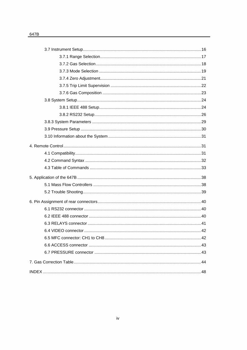
3.7 Instrument Setup.......................................................................................................16
3.7.1 Range Selection........................................................................................17
3.7.2 Gas Selection............................................................................................18
3.7.3 Mode Selection .........................................................................................19
3.7.4 Zero Adjustment........................................................................................21
3.7.5 Trip Limit Supervision ...............................................................................22
3.7.6 Gas Composition ......................................................................................23
3.8 System Setup............................................................................................................24
3.8.1 IEEE 488 Setup.........................................................................................24
3.8.2 RS232 Setup.............................................................................................26
3.8.3 System Parameters ...............................................................................................29
3.9 Pressure Setup .........................................................................................................30
3.10 Information about the System .................................................................................31
4. Remote Control........................................................................................................................31
4.1 Compatibility..............................................................................................................31
4.2 Command Syntax .....................................................................................................32
4.3 Table of Commands .................................................................................................33
5. Application of the 647B ............................................................................................................38
5.1 Mass Flow Controllers ..............................................................................................38
5.2 Trouble Shooting.......................................................................................................39
6. Pin Assignment of rear connectors ..........................................................................................40
6.1 RS232 connector ......................................................................................................40
6.2 IEEE 488 connector ..................................................................................................40
6.3 RELAYS connector ...................................................................................................41
6.4 VIDEO connector ......................................................................................................42
6.5 MFC connector: CH1 to CH8....................................................................................42
6.6 ACCESS connector ..................................................................................................43
6.7 PRESSURE connector .............................................................................................43
7. Gas Correction Table...............................................................................................................44
INDEX ..........................................................................................................................................48
647B
1
1. General
1.1The Multi Gas Controller (MGC) Type 647B
The 647B is designed to control Mass Flow Controllers (MFC) with complex requirements to theprocess. It allows different configuration.
Warning The safety instructions in this document must be kept. Please, takealso a special note of all highlighted text in this document.
- Various master/slave configurations within several groups of channels.
- External control of mass flow controllers.
- Regulation of the pressure with a constant gas flow ratio.
1.2 CE conformity
The device complies to the CE regulations and conformity is declared to the following standards:
- EN 55011 / 3.1991; Group 1; class B
- EN 50082-1 1992
- PrEN 50082-2 1992
- IEC 801-2, IEC 801-3, IEC 801-4
- EN 61010 ; 1993
1.3 Options
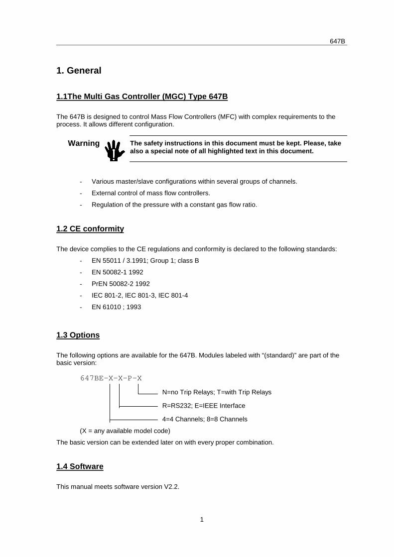
The following options are available for the 647B. Modules labeled with “(standard)” are part of thebasic version:
647BE-X-X-P-X
(X = any available model code)
The basic version can be extended later on with every proper combination.
1.4 Software
This manual meets software version V2.2.
N=no Trip Relays; T=with Trip Relays
R=RS232; E=IEEE Interface
4=4 Channels; 8=8 Channels
647B
2
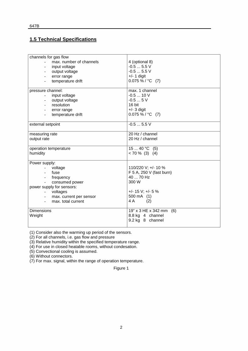
1.5 Technical Specifications
channels for gas flow- max. number of channels- input voltage- output voltage- error range- temperature drift
4 (optional 8)-0.5 ... 5.5 V-0.5 ... 5.5 V+/- 1 digit0.075 % / °C (7)
pressure channel:- input voltage- output voltage- resolution- error range- temperature drift
max. 1 channel-0.5 ... 10 V-0.5 ... 5 V16 bit+/- 3 digit0.075 % / °C (7)
external setpoint -0.5 ... 5.5 V
measuring rateoutput rate
20 Hz / channel20 Hz / channel
operation temperaturehumidity
15 ... 40 °C (5)< 70 % (3) (4)
Power supply:- voltage- fuse- frequency- consumed power
power supply for sensors:- voltages- max. current per sensor- max. total current
110/220 V; +/- 10 %F 5 A, 250 V (fast burn)40 ... 70 Hz300 W
+/- 15 V; +/- 5 %500 mA (1)4 A (2)
DimensionsWeight
19” x 3 HE x 342 mm (6)8.8 kg 4 channel9.2 kg 8 channel
(1) Consider also the warming up period of the sensors.(2) For all channels, i.e. gas flow and pressure(3) Relative humidity within the specified temperature range.(4) For use in closed heatable rooms, without condesation.(5) Convectional cooling is assumed.(6) Without connectors.(7) For max. signal, within the range of operation temperature.
Figure 1
647B
3
1.6 Drawings
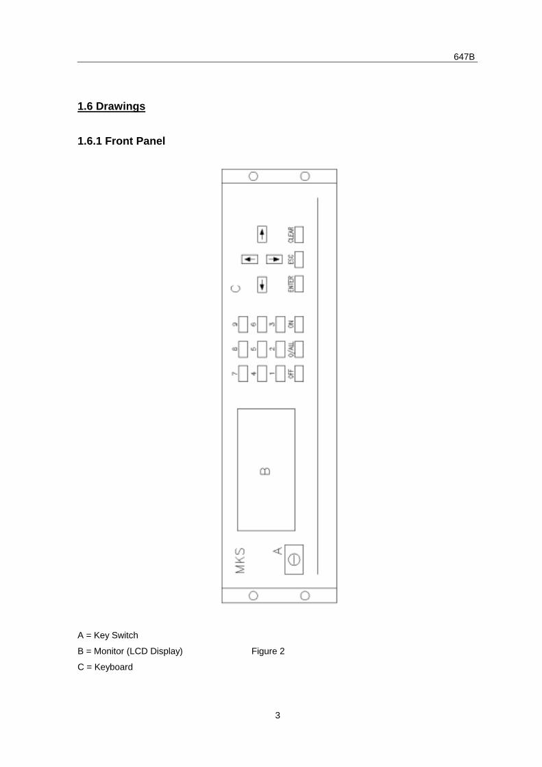
1.6.1 Front Panel
A = Key Switch
B = Monitor (LCD Display) Figure 2
C = Keyboard
647B
4
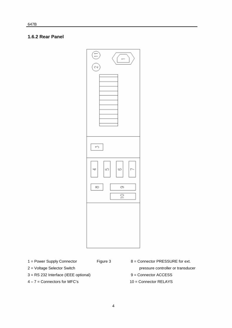
1.6.2 Rear Panel
1 = Power Supply Connector Figure 3 8 = Connector PRESSURE for ext.
2 = Voltage Selector Switch pressure controller or transducer
3 = RS 232 Interface (IEEE optional) 9 = Connector ACCESS
4 – 7 = Connectors for MFC’s 10 = Connector RELAYS
647B
5
1.7 Safety Information
1.7.1 Symbols Used in this Instruction Manual
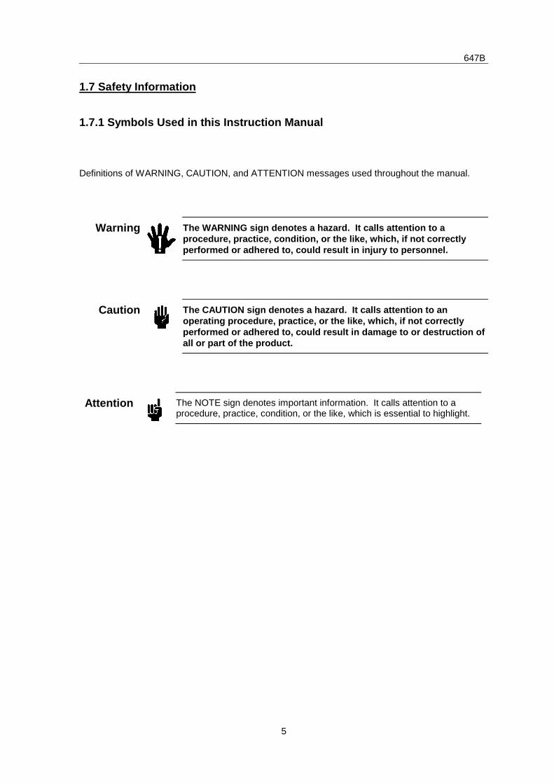
Definitions of WARNING, CAUTION, and ATTENTION messages used throughout the manual.
Warning The WARNING sign denotes a hazard. It calls attention to aprocedure, practice, condition, or the like, which, if not correctlyperformed or adhered to, could result in injury to personnel.
Caution The CAUTION sign denotes a hazard. It calls attention to anoperating procedure, practice, or the like, which, if not correctlyperformed or adhered to, could result in damage to or destruction ofall or part of the product.
Attention The NOTE sign denotes important information. It calls attention to aprocedure, practice, condition, or the like, which is essential to highlight.
647B
6
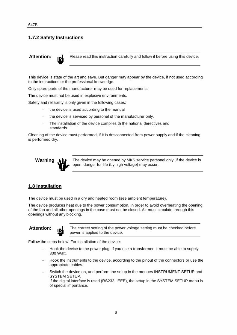
1.7.2 Safety Instructions
Attention: Please read this instruction carefully and follow it before using this device.
This device is state of the art and save. But danger may appear by the device, if not used accordingto the instructions or the professional knowledge.
Only spare parts of the manufacturer may be used for replacements.
The device must not be used in explosive environments.
Safety and reliability is only given in the following cases:
- the device is used according to the manual
- the device is serviced by personel of the manufacturer only.
- The installation of the device complies th the national derectives andstandards.
Cleaning of the device must performed, if it is desconnected from power supply and if the cleaningis performed dry.
Warning The device may be opened by MKS service personel only. If the device isopen, danger for life (by high voltage) may occur.
1.8 Installation
The device must be used in a dry and heated room (see ambient temperature).
The device produces heat due to the power consumption. In order to avoid overheating the openingof the fan and all other openings in the case must not be closed. Air must circulate through thisopenings without any blocking.
Attention: The correct setting of the power voltage setting must be checked beforepower is applied to the device.
Follow the steps below. For installation of the device:
- Hook the device to the power plug. If you use a transformer, it must be able to supply300 Watt.
- Hook the instruments to the device, according to the pinout of the connectors or use theappropirate cables.
- Switch the device on, and perform the setup in the menues INSTRUMENT SETUP andSYSTEM SETUP.If the digital interface is used (RS232, IEEE), the setup in the SYSTEM SETUP menu isof special importance.
647B
7
- If you have problems booting the system, you should read the chapter “Reset ofSystem” and “Applications of the 647B”.
1.9 Symbols at the case
The device shows some symbols, which are explained here:
- The “!” ( ) says to watch the documentation/manual.
- The type label gives information about the device type, the serial number and sometechnical date.
- The label close to the fuse holder tells the specification of spare fuses: F 5A, 250V.
1.10 Accessories
The 647B comes with the following accessories:
- Sub-D connector sets for the instruments:
4 channel device: ZB-198 channel deivce: ZB-20
- Power cable: Y-0984492
- Manual: Y-1957647
- 2*handles for the case: Y-5150011
- 4*screws for the handles: Y-1600005
1.11 Cables
Refer to the instruction manuals of the respective mass flow meters, mass flow controllers andpressure transducers for cable information.
1.12 Service
In case of problems or failure of the device, please contact your local MKS representative. The lastpage of this manual contains a list of service and calibration centers.
647B
8
2. Operating Instructions
2.1 The User Interface
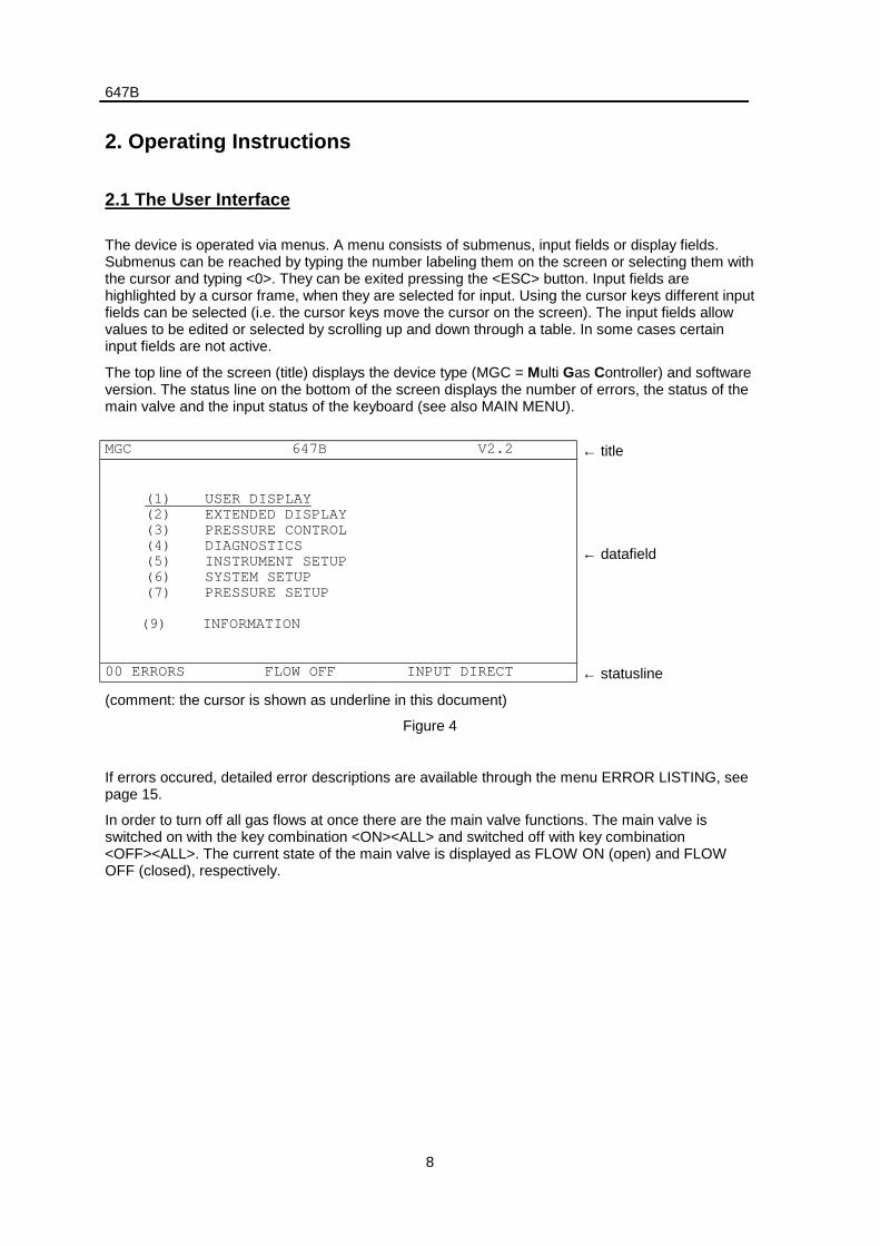
The device is operated via menus. A menu consists of submenus, input fields or display fields.Submenus can be reached by typing the number labeling them on the screen or selecting them withthe cursor and typing <0>. They can be exited pressing the <ESC> button. Input fields arehighlighted by a cursor frame, when they are selected for input. Using the cursor keys different inputfields can be selected (i.e. the cursor keys move the cursor on the screen). The input fields allowvalues to be edited or selected by scrolling up and down through a table. In some cases certaininput fields are not active.
The top line of the screen (title) displays the device type (MGC = Multi Gas Controller) and softwareversion. The status line on the bottom of the screen displays the number of errors, the status of themain valve and the input status of the keyboard (see also MAIN MENU).
MGC 647B V2.2 ← title
(1) USER DISPLAY(2) EXTENDED DISPLAY(3) PRESSURE CONTROL(4) DIAGNOSTICS(5) INSTRUMENT SETUP(6) SYSTEM SETUP(7) PRESSURE SETUP
(9) INFORMATION
← datafield
00 ERRORS FLOW OFF INPUT DIRECT ← statusline
(comment: the cursor is shown as underline in this document)
Figure 4
If errors occured, detailed error descriptions are available through the menu ERROR LISTING, seepage 15.
In order to turn off all gas flows at once there are the main valve functions. The main valve isswitched on with the key combination <ON><ALL> and switched off with key combination<OFF><ALL>. The current state of the main valve is displayed as FLOW ON (open) and FLOWOFF (closed), respectively.
647B
9
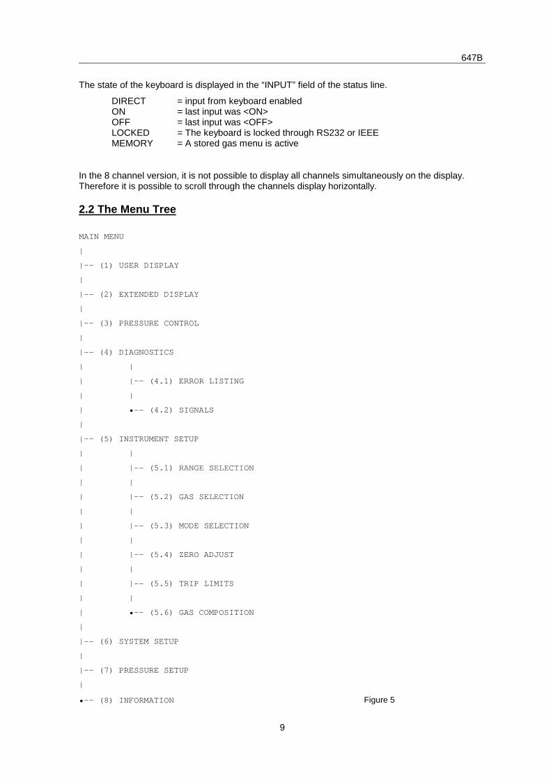
The state of the keyboard is displayed in the “INPUT” field of the status line.
DIRECT = input from keyboard enabledON = last input was <ON>OFF = last input was <OFF>LOCKED = The keyboard is locked through RS232 or IEEEMEMORY = A stored gas menu is active
In the 8 channel version, it is not possible to display all channels simultaneously on the display.Therefore it is possible to scroll through the channels display horizontally.
2.2 The Menu Tree
MAIN MENU
|
|-- (1) USER DISPLAY
|
|-- (2) EXTENDED DISPLAY
|
|-- (3) PRESSURE CONTROL
|
|-- (4) DIAGNOSTICS
| |
| |-- (4.1) ERROR LISTING
| |
| •-- (4.2) SIGNALS
|
|-- (5) INSTRUMENT SETUP
| |
| |-- (5.1) RANGE SELECTION
| |
| |-- (5.2) GAS SELECTION
| |
| |-- (5.3) MODE SELECTION
| |
| |-- (5.4) ZERO ADJUST
| |
| |-- (5.5) TRIP LIMITS
| |
| •-- (5.6) GAS COMPOSITION
|
|-- (6) SYSTEM SETUP
|
|-- (7) PRESSURE SETUP
|
•-- (8) INFORMATION Figure 5
647B
10
2.3 Reset of System
There are four types of Reset:
- First Start Reset
- Power Up Reset
- Hardware Reset
- Reset to Default
Attention: All of the above resets will switch off all gas flow controllers.
First Start Reset will appear if the system is started for the first time or if the RAM has beenreplaced. This has usually already taken place at the factory. All data in the RAM are initialized withthis reset. A quick tap on keys <7> and <9> will force the system to First Start Reset.
If the device refuses to come up on power on, press button <8> while switching thedevice on in order to perform a total reset (equal to First Start Reset). This problem canhave 2 reasons:
- Data in memory was destroyed through a transient. The described procedure will fixthis problem.
- There is an error in the hardware. If the Start Up problem occurs more than oncecontact your local MKS service center.
Power Up Reset is performed everytime the system is switched on. It resets all data which areneeded for system administration. Data of process parameters are notaffected.
Hardware Reset is similar to Power Up Reset. It is triggered by the keys <OFF> and <cursor right>pressed at the same time. In any case Power Up or Hardware Reset leads to the MAIN MENU.
Reset to Default sets all process parameters to their default value. This reset istriggered in SYSTEM SETUP menu.
After the device has been turned off, one should wait for ca. 15 seconds before turning it on again.
2.4 Display adjustment
The viewing angle of the LCD display and the timeout setting of its back light saver, may be set inSYSTEM BACKUP menu.
647B
11
3. Functionality
3.1 The MAIN MENU
After turning on the power switch (1) the MAIN MENU is displayed. From this menu the differentsubmenus are accessible. (See also figure 4).
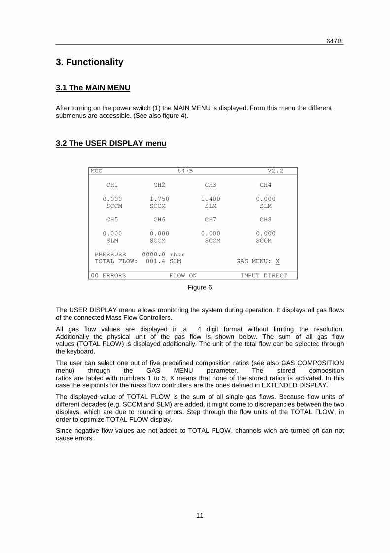
3.2 The USER DISPLAY menu
MGC 647B V2.2
CH1 CH2 CH3 CH4
0.000 1.750 1.400 0.000 SCCM SCCM SLM SLM
CH5 CH6 CH7 CH8
0.000 0.000 0.000 0.000 SLM SCCM SCCM SCCM
PRESSURE 0000.0 mbar TOTAL FLOW: 001.4 SLM GAS MENU: X
00 ERRORS FLOW ON INPUT DIRECT
Figure 6
The USER DISPLAY menu allows monitoring the system during operation. It displays all gas flowsof the connected Mass Flow Controllers.
All gas flow values are displayed in a 4 digit format without limiting the resolution.Additionally the physical unit of the gas flow is shown below. The sum of all gas flowvalues (TOTAL FLOW) is displayed additionally. The unit of the total flow can be selected throughthe keyboard.
The user can select one out of five predefined composition ratios (see also GAS COMPOSITIONmenu) through the GAS MENU parameter. The stored compositionratios are labled with numbers 1 to 5. X means that none of the stored ratios is activated. In thiscase the setpoints for the mass flow controllers are the ones defined in EXTENDED DISPLAY.
The displayed value of TOTAL FLOW is the sum of all single gas flows. Because flow units ofdifferent decades (e.g. SCCM and SLM) are added, it might come to discrepancies between the twodisplays, which are due to rounding errors. Step through the flow units of the TOTAL FLOW, inorder to optimize TOTAL FLOW display.
Since negative flow values are not added to TOTAL FLOW, channels wich are turned off can notcause errors.
647B
12
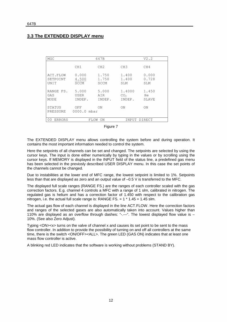
3.3 The EXTENDED DISPLAY menu
MGC 647B V2.2
CH1 CH2 CH3 CH4
ACT.FLOW 0.000 1.750 1.400 0.000SETPOINT 4.500 1.750 1.400 0.728UNIT SCCM SCCM SLM SLM
RANGE FS. 5.000 5.000 1.4000 1.450GAS USER AIR CO2 HeMODE INDEP. INDEP. INDEP. SLAVE
STATUS OFF ON ON ONPRESSURE 0000.0 mbar
00 ERRORS FLOW ON INPUT DIRECT
Figure 7
The EXTENDED DISPLAY menu allows controlling the system before and during operation. Itcontains the most important information needed to control the system.
Here the setpoints of all channels can be set and changed. The setpoints are selected by using thecursor keys. The input is done either numerically by typing in the values or by scrolling using thecursor keys. If MEMORY is displayed in the INPUT field of the status line, a predefined gas menuhas been selected in the previosly described USER DISPLAY menu. In this case the set points ofthe channels cannot be changed.
Due to instabilities at the lower end of MFC range, the lowest setpoint is limited to 1%. Setpointsless than that are displayed as zero and an output value of –0.5 V is transferred to the MFC.
The displayed full scale ranges (RANGE FS.) are the ranges of each controller scaled with the gascorrection factors. E.g. channel 4 controls a MFC with a range of 1 slm, calibrated in nitrogen. Theregulated gas is helium and has a correction factor of 1.450 with respect to the calibration gasnitrogen, i.e. the actual full scale range is: RANGE FS. = 1 * 1.45 = 1.45 slm.
The actual gas flow of each channel is displayed in the line ACT.FLOW. Here the correction factorsand ranges of the selected gases are also automatically taken into account. Values higher than110% are displayed as an overflow through dashes: “-.---“. The lowest displayed flow value is –10%. (See also Zero Adjust).
Typing <ON><x> turns on the valve of channel x and causes its set point to be sent to the massflow controller. In addition to provide the possibility of turning on and off all controllers at the sametime, there is the switch <ON/OFF><ALL>. The green LED (GAS ON) indicates that at least onemass flow controller is active.
A blinking red LED indicates that the software is working without problems (STAND BY).
647B
13
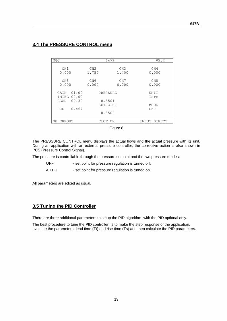
3.4 The PRESSURE CONTROL menu
MGC 647B V2.2
CH1 CH2 CH3 CH4 0.000 1.750 1.400 0.000
CH5 CH6 CH7 CH8 0.000 0.000 0.000 0.000
GAIN 01.00 PRESSURE UNIT INTEG 02.00 Torr LEAD 00.30 0.3501 SETPOINT MODE PCS 0.467 OFF 0.3500
00 ERRORS FLOW ON INPUT DIRECT
Figure 8
The PRESSURE CONTROL menu displays the actual flows and the actual pressure with its unit.During an application with an external pressure controller, the corrective action is also shown inPCS (Pressure Control Signal).
The pressure is controllable through the pressure setpoint and the two pressure modes:
OFF - set point for pressure regulation is turned off.
AUTO - set point for pressure regulation is turned on.
All parameters are edited as usual.
3.5 Tuning the PID Controller
There are three additional parameters to setup the PID algorithm, with the PID optional only.
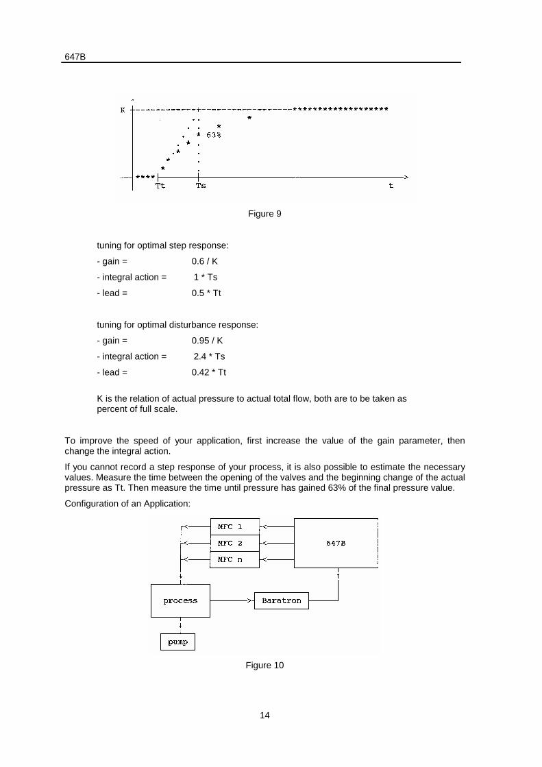
The best procedure to tune the PID controller, is to make the step response of the application,evaluate the parameters dead time (Tt) and rise time (Ts) and then calculate the PID parameters.
647B
14
Figure 9
tuning for optimal step response:
- gain = 0.6 / K
- integral action = 1 * Ts
- lead = 0.5 * Tt
tuning for optimal disturbance response:
- gain = 0.95 / K
- integral action = 2.4 * Ts
- lead = 0.42 * Tt
K is the relation of actual pressure to actual total flow, both are to be taken aspercent of full scale.
To improve the speed of your application, first increase the value of the gain parameter, thenchange the integral action.
If you cannot record a step response of your process, it is also possible to estimate the necessaryvalues. Measure the time between the opening of the valves and the beginning change of the actualpressure as Tt. Then measure the time until pressure has gained 63% of the final pressure value.
Configuration of an Application:
Figure 10
647B
15
3.6 Diagnosis of System
3.6.1 The ERROR LISTING menu
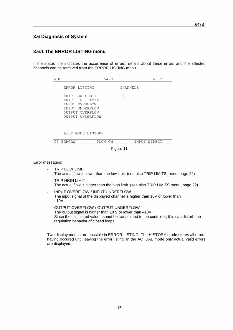
If the status line indicates the occurrence of errors, details about these errors and the affectedchannels can be retrieved from the ERROR LISTING menu.
MGC 647B V2.2
ERROR LISTING CHANNELS
TRIP LOW LIMIT 12 TRIP HIGH LIMIT 2 INPUT OVERFLOW INPUT UNDERFLOW OUTPUT OVERFLOW OUTPUT UNDERFLOW
LIST MODE HISTORY
03 ERRORS FLOW ON INPUT DIRECT
Figure 11
Error messages:
- TRIP LOW LIMITThe actual flow is lower than the low limit. (see also TRIP LIMITS menu, page 22)
- TRIP HIGH LIMITThe actual flow is higher than the high limit. (see also TRIP LIMITS menu, page 22)
- INPUT OVERFLOW / INPUT UNDERFLOWThe input signal of the displayed channel is higher than 10V or lower than–10V.
- OUTPUT OVERFLOW / OUTPUT UNDERFLOWThe output signal is higher than 10 V or lower than –10V.Since the calculated value cannot be transmitted to the controller, this can disturb theregulation behavior of closed loops.
Two display modes are possible in ERROR LISTING. The HISTORY mode stores all errorshaving occured until leaving the error listing. In the ACTUAL mode only actual valid errorsare displayed.
647B
16
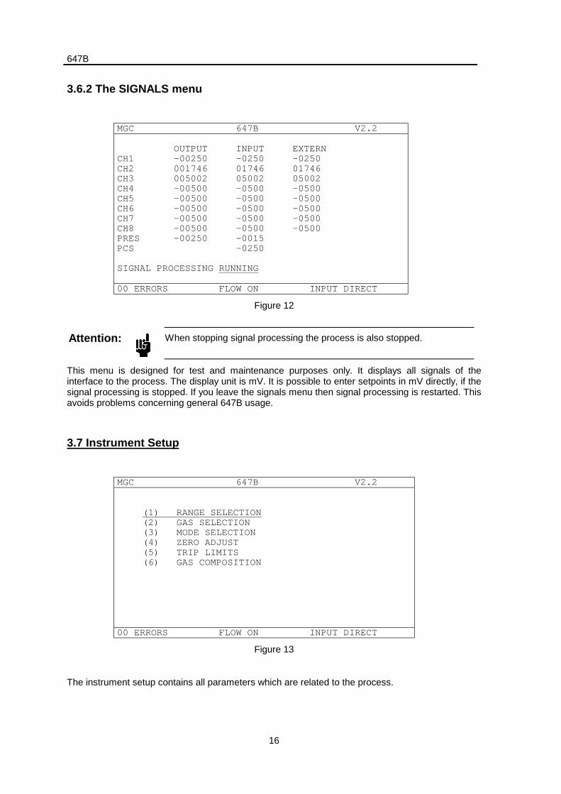
3.6.2 The SIGNALS menu
MGC 647B V2.2
OUTPUT INPUT EXTERNCH1 -00250 -0250 -0250CH2 001746 01746 01746CH3 005002 05002 05002CH4 -00500 -0500 -0500CH5 -00500 -0500 -0500CH6 -00500 -0500 -0500CH7 -00500 -0500 -0500CH8 -00500 -0500 -0500PRES -00250 -0015PCS -0250
SIGNAL PROCESSING RUNNING
00 ERRORS FLOW ON INPUT DIRECT
Figure 12
Attention: When stopping signal processing the process is also stopped.
This menu is designed for test and maintenance purposes only. It displays all signals of theinterface to the process. The display unit is mV. It is possible to enter setpoints in mV directly, if thesignal processing is stopped. If you leave the signals menu then signal processing is restarted. Thisavoids problems concerning general 647B usage.
3.7 Instrument Setup
MGC 647B V2.2
(1) RANGE SELECTION(2) GAS SELECTION(3) MODE SELECTION(4) ZERO ADJUST(5) TRIP LIMITS(6) GAS COMPOSITION
00 ERRORS FLOW ON INPUT DIRECT
Figure 13
The instrument setup contains all parameters which are related to the process.

647B
17
3.7.1 Range Selection
MGC 647B V2.2
CH1 CH2 CH3 CH4
ACT.FLOW 0.000 1.750 1.400 0.000UNIT SCCM SCCM SLM SLM
RANGE FS. 5.000 5.000 2.000 1.000
STATUS OFF ON ON ON
00 ERRORS FLOW ON INPUT DIRECT
Figure 14
The following ranges are available:
1 sccm,10 sccm,
100 sccm,1 slm,
10 slm,100 slm,1 scmm,
1 scfh,10 scfh,
100 scfh,1 scfm,
10 scfm,100 scfm,
2 sccm,20 sccm,
200 sccm,2 slm,
20 slm,200 slm,
2 scfh,20 scfh,
200 scfh,2 scfm,
20 scfm,200 scfm,
5 sccm,50 sccm,
500 sccm,5 slm,
30 slm,300 slm,
5 scfh,50 scfh,
500 scfh,5 scfm,
50 scfm,500 scfm,
50 slm,400 slm, 500slm,
sccm = standard cubic centimeter per minuteslm = standard cubic liter per minutescmm = standard cubic meter per minutescfh = standard cubic feet per hourscfm = standard cubic feet per minute
647B
18
3.7.2 Gas Selection
MGC 647B V2.2
CH1 CH2 CH3 CH4
ACT.FLOW 0.000 1.750 1.400 0.000UNIT SCCM SCCM SLM SLM
GAS USER AIR CO2 HeFACTOR 1.000 1.000 0.700 1.450
STATUS OFF ON ON ON
00 ERRORS FLOW ON INPUT DIRECT
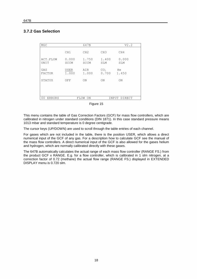
Figure 15
This menu contains the table of Gas Correction Factors (GCF) for mass flow controllers, which arecalibrated in nitrogen under standard conditions (DIN 1871). In this case standard pressure means1013 mbar and standard temperature is 0 degree centigrade.
The cursor keys (UP/DOWN) are used to scroll through the table entries of each channel.
For gases which are not included in the table, there is the position USER, which allows a directnumerical input of the GCF of any gas. For a description how to calculate GCF see the manual ofthe mass flow controllers. A direct numerical input of the GCF is also allowed for the gases heliumand hydrogen, which are normally calibrated directly with these gases.
The 647B automatically calculates the actual range of each mass flow controller (RANGE FS.) fromthe product GCF x RANGE. E.g. for a flow controller, which is calibrated in 1 slm nitrogen, at acorrection factor of 0.72 (methane) the actual flow range (RANGE FS.) displayed in EXTENDEDDISPLAY menu is 0.720 slm.
647B
19
3.7.3 Mode Selection
MGC 647B V2.2
CH1 CH2 CH3 CH4
ACT.FLOW 0.000 1.750 1.400 0.000UNIT SCCM SCCM SLM SLM
MODE INDEP. INDEP. INDEP. SLAVEINDEX 1
STATUS OFF ON ON ON
00 ERRORS FLOW ON INPUT DIRECT
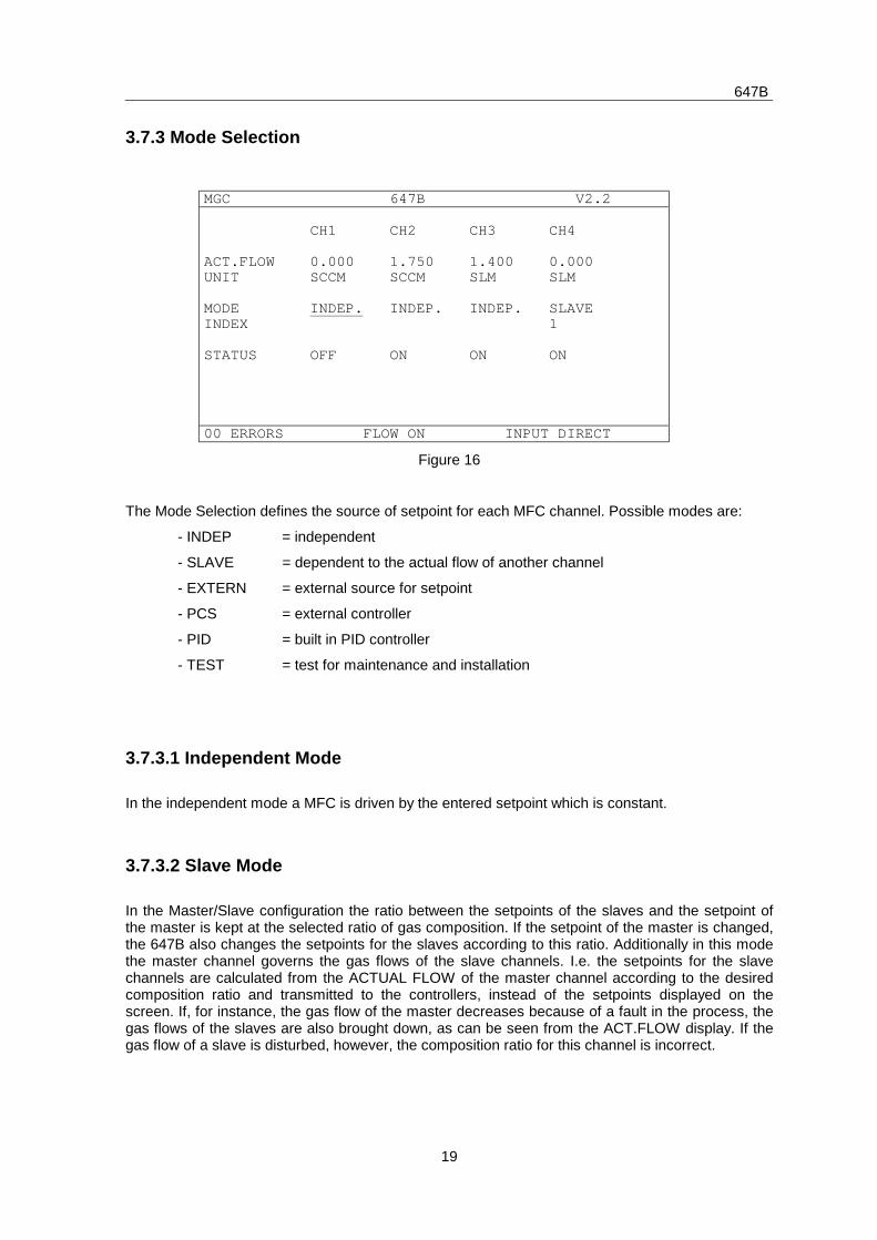
Figure 16
The Mode Selection defines the source of setpoint for each MFC channel. Possible modes are:
- INDEP = independent
- SLAVE = dependent to the actual flow of another channel
- EXTERN = external source for setpoint
- PCS = external controller
- PID = built in PID controller
- TEST = test for maintenance and installation
3.7.3.1 Independent Mode
In the independent mode a MFC is driven by the entered setpoint which is constant.
3.7.3.2 Slave Mode
In the Master/Slave configuration the ratio between the setpoints of the slaves and the setpoint ofthe master is kept at the selected ratio of gas composition. If the setpoint of the master is changed,the 647B also changes the setpoints for the slaves according to this ratio. Additionally in this modethe master channel governs the gas flows of the slave channels. I.e. the setpoints for the slavechannels are calculated from the ACTUAL FLOW of the master channel according to the desiredcomposition ratio and transmitted to the controllers, instead of the setpoints displayed on thescreen. If, for instance, the gas flow of the master decreases because of a fault in the process, thegas flows of the slaves are also brought down, as can be seen from the ACT.FLOW display. If thegas flow of a slave is disturbed, however, the composition ratio for this channel is incorrect.
647B
20
E.g. a ratio of 5:1 (master:slave) means:
Setpoint of slave = act. flow of master * 0.2
The master channel is determined by the index which is associated with the slave channel. Theadvantages hereby are that the master remains free for declaration in other modes and more thanone master is possible. With this declaration technique, however, useless circular reference chains,which might even be dangerous for the application, could appear. In order ro avoid this, thesoftware checks out each input and rejects it if necessary. Therefore, this solution offers fulladvantages without risks.
Example 1: (menu extract)
CH1 CH2 CH3 CH4
MODE INDEP. SLAVE SLAVE INDEP.
INDEX 1 2
In this example channel 1 is master of channel 2, which is master of channel 3. This is an openreference chain. The index number of a slave indicates its master channel. This declarationtechnique applicated to channel 2 as master has the advantage, that this channel may be declaredas slave while being a master. Channel 4 is independent.
Example 2: (menu extract)
CH1 CH2 CH3 CH4
MODE SLAVE SLAVE SLAVE INDEP.
INDEX 3 1 2
This example shows a circular reference chain, which will never appear on 647B screen. Thesoftware prevents its appearance by consequently rejecting wrong input. This is the reason whysome of the user’s input might be rejected.
3.7.3.3 External Mode
This mode enables external control of the MFCs through the auxiliary connector. The MFC’ssetpoint is caculated as the product of setpoint in menu EXTENDED MENU and the signal at theauxiliary input. E.g.
Setpoint of MFC = setpoint in EXTENDED MENU * auxiliary input / 5 V
3.7.3.4 PCS Mode
In the PRESSURE CONTROL mode (PCS) the 647B serves as the regulating unit for a pressurecontroller (e.g. type 250). All gas flow channels which are configured in the PCS mode areregulated through the pressure control signal (PCS) according to the ratio of their set points.
647B
21
3.7.3.5 PID Mode
In this mode MFCs are driven by a PID algorithm (see also menu: PRESSURE CONTROL). Thismode is only available with the PID option.
3.7.3.6 Test Mode
In this mode the 647B generates a test signal, which may be useful for installation procedures. Thetest signal is a saw tooth beetween zero and 100% with a period of 4 sec.
3.7.4 Zero Adjustment
MGC 647B V2.2
CH1 CH2 CH3 CH4
ACT.FLOW 0.000 1.750 1.400 0.000UNIT SCCM SCCM SLM SLM
ZERO VALUE 0.005 -.004 0.002 -.002ZERO ADJUST EXEC EXEC EXEC EXEC
STATUS OFF ON ON ON
00 ERRORS FLOW ON INPUT DIRECT
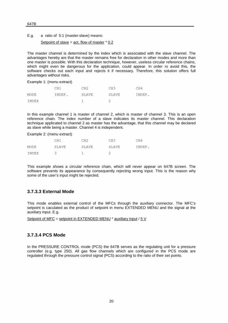
Figure 17
To trigger the Auto Zero function, the status needs to be changed from EXEC (executable) to ACT(active) through the cursor keys. The status DONE or FAIL displays the completition of the function.The status FAIL indicates that the offset was too large and a new zero value was not generated.FAIL status may also appear if the channel is switched on. The status ACT appears on the screenfor a very short time, so that it is usually not noticed.
The measured value (the zero offset of the sensor of the mass flow controller) is displayed in thefield ZERO VALUE. In order to correct the zero offset, this value is subtracted from actual flow andadded to the setpoint output. This way the controller gets a corrected setpoint and thus equalizingthe sensor signal’s error.
If necessary, one can enter the zero offset directly.
647B
22
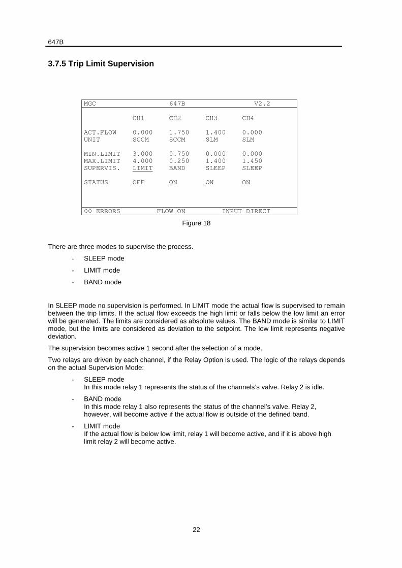
3.7.5 Trip Limit Supervision
MGC 647B V2.2
CH1 CH2 CH3 CH4
ACT.FLOW 0.000 1.750 1.400 0.000UNIT SCCM SCCM SLM SLM
MIN.LIMIT 3.000 0.750 0.000 0.000MAX.LIMIT 4.000 0.250 1.400 1.450SUPERVIS. LIMIT BAND SLEEP SLEEP
STATUS OFF ON ON ON
00 ERRORS FLOW ON INPUT DIRECT
Figure 18
There are three modes to supervise the process.
- SLEEP mode
- LIMIT mode
- BAND mode
In SLEEP mode no supervision is performed. In LIMIT mode the actual flow is supervised to remainbetween the trip limits. If the actual flow exceeds the high limit or falls below the low limit an errorwill be generated. The limits are considered as absolute values. The BAND mode is similar to LIMITmode, but the limits are considered as deviation to the setpoint. The low limit represents negativedeviation.
The supervision becomes active 1 second after the selection of a mode.
Two relays are driven by each channel, if the Relay Option is used. The logic of the relays dependson the actual Supervision Mode:
- SLEEP modeIn this mode relay 1 represents the status of the channels’s valve. Relay 2 is idle.
- BAND modeIn this mode relay 1 also represents the status of the channel’s valve. Relay 2,however, will become active if the actual flow is outside of the defined band.
- LIMIT modeIf the actual flow is below low limit, relay 1 will become active, and if it is above highlimit relay 2 will become active.
647B
23
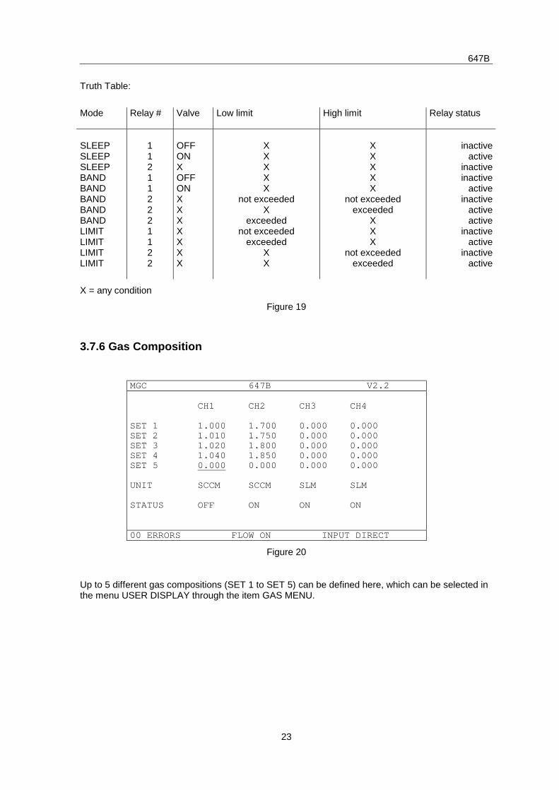
Truth Table:
Mode Relay # Valve Low limit High limit Relay status
SLEEPSLEEPSLEEPBANDBANDBANDBANDBANDLIMITLIMITLIMITLIMIT
112112221122
OFFONXOFFONXXXXXXX
XXXXX
not exceededX
exceedednot exceeded
exceededXX
XXXXX
not exceededexceeded
XXX
not exceededexceeded
inactiveactive
inactiveinactive
activeinactive
activeactive
inactiveactive
inactiveactive
X = any condition
Figure 19
3.7.6 Gas Composition
MGC 647B V2.2
CH1 CH2 CH3 CH4
SET 1 1.000 1.700 0.000 0.000SET 2 1.010 1.750 0.000 0.000SET 3 1.020 1.800 0.000 0.000SET 4 1.040 1.850 0.000 0.000SET 5 0.000 0.000 0.000 0.000
UNIT SCCM SCCM SLM SLM
STATUS OFF ON ON ON
00 ERRORS FLOW ON INPUT DIRECT
Figure 20
Up to 5 different gas compositions (SET 1 to SET 5) can be defined here, which can be selected inthe menu USER DISPLAY through the item GAS MENU.
647B
24
3.8 System Setup
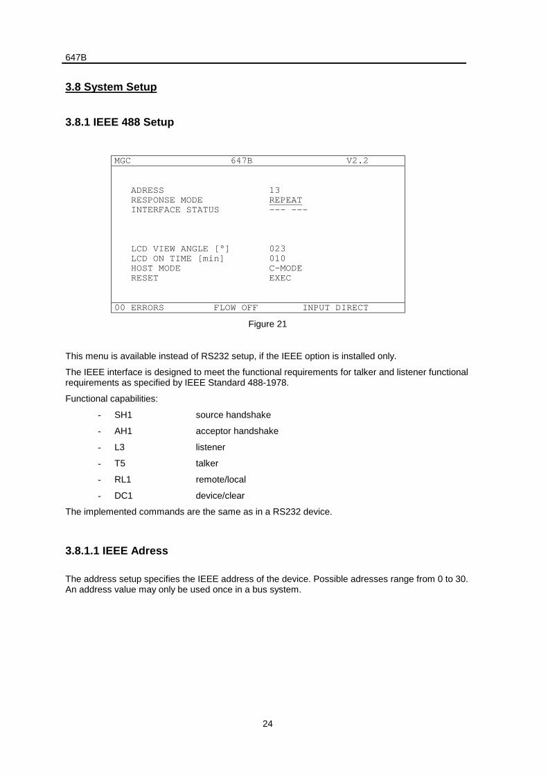
3.8.1 IEEE 488 Setup
MGC 647B V2.2
ADRESS 13 RESPONSE MODE REPEAT INTERFACE STATUS --- ---
LCD VIEW ANGLE [°] 023 LCD ON TIME [min] 010 HOST MODE C-MODE RESET EXEC
00 ERRORS FLOW OFF INPUT DIRECT
Figure 21
This menu is available instead of RS232 setup, if the IEEE option is installed only.
The IEEE interface is designed to meet the functional requirements for talker and listener functionalrequirements as specified by IEEE Standard 488-1978.
Functional capabilities:
- SH1 source handshake
- AH1 acceptor handshake
- L3 listener
- T5 talker
- RL1 remote/local
- DC1 device/clear
The implemented commands are the same as in a RS232 device.
3.8.1.1 IEEE Adress
The address setup specifies the IEEE address of the device. Possible adresses range from 0 to 30.An address value may only be used once in a bus system.
647B
25
3.8.1.2 Response Modes
There are three modes, that specify the 647B’s reaction to a data request of the bus controller.
- QUIET
- POLLING
- REPEAT
In the QUIET mode, the 647B only responds to a command if data are pending. There is noresponse if errors occur or if a command results in no data at all.
In the POLLING mode each command results an a response. Either data, an error string or anempty acknowledge (i.e. <CR><LF>) is sent back to the controller.
Both modes QUIET and POLLING do not respond if there has been no request through a previouscommand.
The REPEAT mode is similar to POLLING, but it responds to each data request of the buscontroller. If the controller has not sent a command before the request, the 647B repeats the lastgiven command. If there has been no last command e.g. after power up, the command “ID” isperformed.
3.8.1.3 Interface Status
The interface status displays two flags, the adress status and the communication status.
- adress status: ---, TLK, LSN
- communication status: ---, RMT, LLO
TLK means that the device is adressed as talker, LSN means an adressing as listener. Threedashes (---) are displayed if any other device is adressed.
The bus controller is able to set the device to remote (RMT) or local (---) status. If the device is inremote status it is not possible to operate it through the keyboard, but it can be switched back tolocal by the <ESC> key until the next command appears. If the device is set to local lockout (LLO)status by the controller there is no reset to local status through the keyboard possible.
Regardless of the IEEE status, the keyboard is also disabled by the command “KD” and enabled by“KE”. In order to work with the keyboard it must be enabled from command level (i.e. “KE”) and buslevel (i.e. local).
The status is updated 5 times a second, but as the communication could be faster than that, it ispossible that not all changes of status will be visible.
3.8.1.4 Examples
The following examples show the usage of a 647B through the IEEE interface. The examples aregiven in HP85 basic.
647B
26
Program to display the act. flow of channel 1 using QUIET mode:
10 LOCAL 7 ! keyboard remains enabled20 OUTPUT 713; “ID” ! request for the advice ID30 ENTER 713; A$ ! bus request for ID data40 DISP A$ ! display ID on the HP85 screen50 OUTPUT 713; “FS 1 0500” ! set setpoint to 50%60 OUTPUT 713; “ON 1” ! switch channel on70 OUTPUT 713; “ON 0” ! ditto80 OUTPUT 713; “FL 1” ! request of 1st channels act.flow90 ENTER 713; A$ ! bus request100 DISP A$ ! display of act.flow110 GOTO 80 ! repeat act flow request
Same program but with REPEAT mode and keyboard disabled:
10 REMOTE 7 ! keyboard remains enabled20 OUTPUT 713; “ID” ! request for the advice ID30 OUTPUT 713; “FS 1 0500” ! bus request for ID data40 OUTPUT 713; “ON 1” ! switch channel on50 OUTPUT 713; “ON 0” ! ditto60 OUTPUT 713; “FL 1” ! request of 1st channels act.flow70 WAIT 1000 ! wait until commands are accepted80 ENTER 713; A$ ! bus request90 DISP A$ ! display of act.flow100 GOTO 80 ! repeat act flow request
For interface language see chapter Remote Control
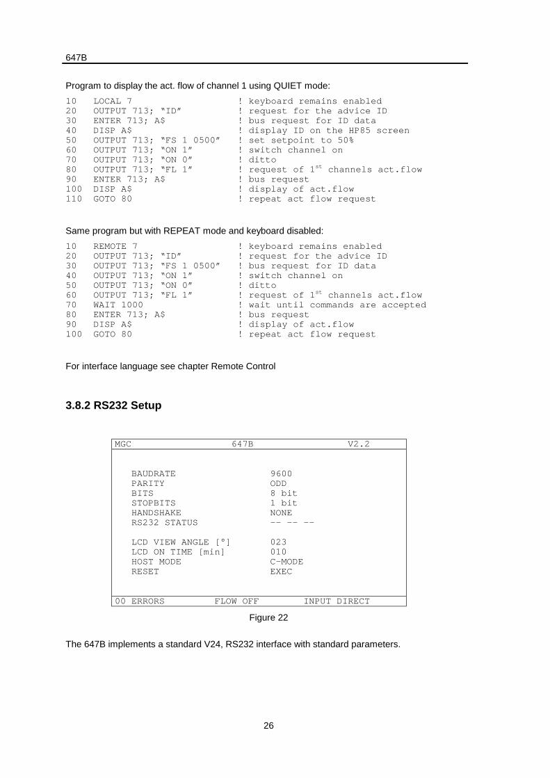
3.8.2 RS232 Setup
MGC 647B V2.2
BAUDRATE 9600 PARITY ODD BITS 8 bit STOPBITS 1 bit HANDSHAKE NONE RS232 STATUS -- -- --
LCD VIEW ANGLE [°] 023 LCD ON TIME [min] 010 HOST MODE C-MODE RESET EXEC
00 ERRORS FLOW OFF INPUT DIRECT
Figure 22
The 647B implements a standard V24, RS232 interface with standard parameters.
647B
27
3.8.2.1 Baudrate
The baudrate defines the transfer speed of characters on the line. The transfer rate of commandsand data is determined by this baudrate and by the processing speed of 647B. The first 30commands will be directed to a buffer at maximum speed, while the transfer of further commands iscontrolled by a handshake protocol. The baudrate must fit to the baudrate of the host computer.
- supported baud rates:50, 75, 110, 150, 300, 600, 1200,1800, 2000, 2400, 3600, 4800, 7200, 9600 Baud
3.8.2.2 Data Link Parameters
The data link parameters must fit to setup of the host computer. Change it according to the setup ofthe host.
- word length7 bit8 bit
- parityNONEEVENODD
- stop bits1 bit2 bit
3.8.2.3 Handshake Protocol
The handshake protocol synchronizes different processing speeds of 647B and host computer. Ifthe receiving device is busy with calculating and therefore not ready to accept more date it stops thetransfer through a handshake protocol. The 647B can accept 30 commands at maximum speeduntil it stops the transfer.
There are three kinds of handshake modes for the communication with the host computer:
- no handshake
- software handshake (XON, XOFF)
- hardware handshake (RTS, CTS)
The usage of one of the above modes depens on the connection to the computer. If thecommunication is run without handshake and the calculating speed do not match, loss of data mayappear.
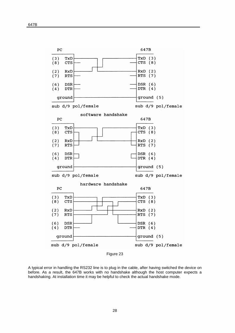
3.8.2.4 Interface Connections
When the 647B software is booting (e.g. at power on or hardware reset) it detects the handshakemode through the cable type on the RS232 line. This mode is displayed in the menu.
647B
28
Figure 23
A typical error in handling the RS232 line is to plug in the cable, after having switched the device onbefore. As a result, the 647B works with no handshake although the host computer expects ahandshaking. At installation time it may be helpful to check the actual handshake mode.
647B
29
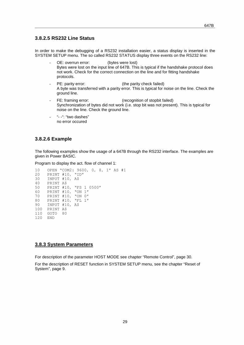
3.8.2.5 RS232 Line Status
In order to make the debugging of a RS232 installation easier, a status display is inserted in theSYSTEM SETUP menu. The so called RS232 STATUS display three events on the RS232 line:
- OE: overrun error: (bytes were lost)Bytes were lost on the input line of 647B. This is typical if the handshake protocol doesnot work. Check for the correct connection on the line and for fitting handshakeprotocols.
- PE: parity error: (the parity check failed)A byte was transferred with a parity error. This is typical for noise on the line. Check theground line.
- FE: framing error: (recognition of stopbit failed)Synchronization of bytes did not work (i.e. stop bit was not present). This is typical fornoise on the line. Check the ground line.
- “- -“: “two dashes”no error occured
3.8.2.6 Example
The following examples show the usage of a 647B through the RS232 interface. The examples aregiven in Power BASIC.
Program to display the act. flow of channel 1:
10 OPEN “COM2: 9600, 0, 8, 1” AS #120 PRINT #10, “ID”30 INPUT #10, A$40 PRINT A$50 PRINT #10, “FS 1 0500”60 PRINT #10, “ON 1”70 PRINT #10, “ON 0”80 PRINT #10, “FL 1”90 INPUT #10, A$100 PRINT A$110 GOTO 80120 END
3.8.3 System Parameters
For description of the parameter HOST MODE see chapter “Remote Control”, page 30.
For the description of RESET function in SYSTEM SETUP menu, see the chapter “Reset ofSystem”, page 9.
647B
30
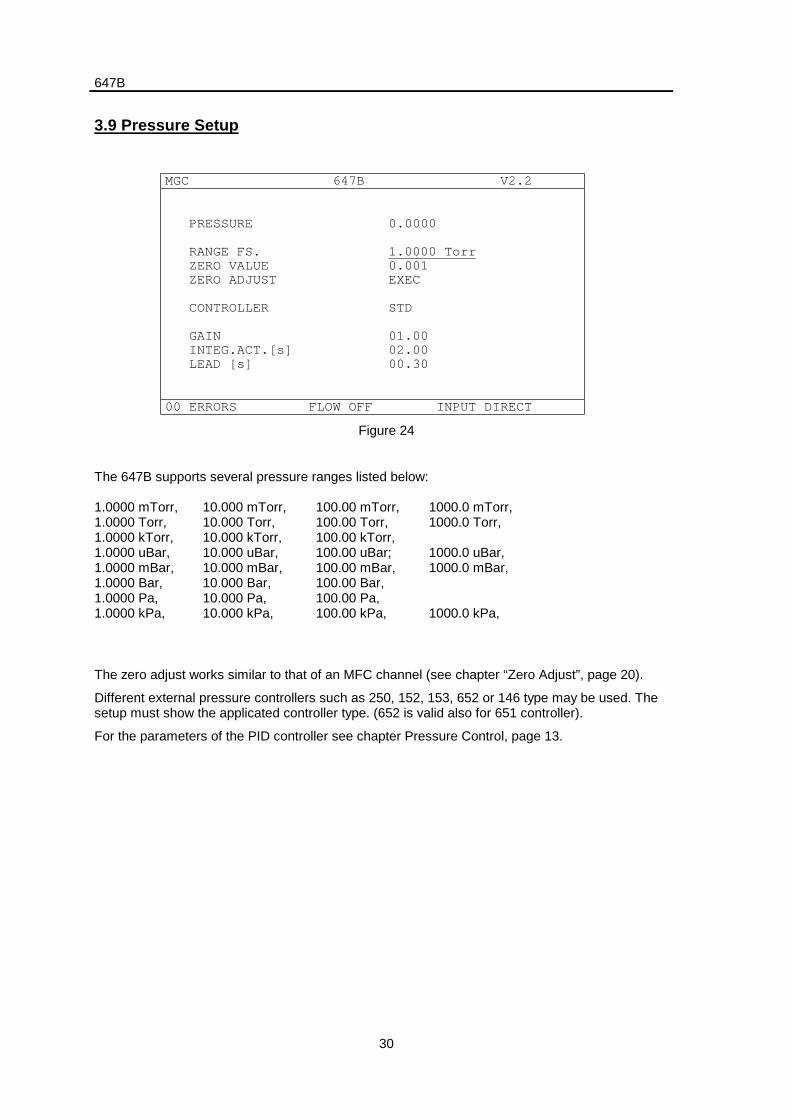
3.9 Pressure Setup
MGC 647B V2.2
PRESSURE 0.0000
RANGE FS. 1.0000 Torr ZERO VALUE 0.001 ZERO ADJUST EXEC
CONTROLLER STD
GAIN 01.00 INTEG.ACT.[s] 02.00 LEAD [s] 00.30
00 ERRORS FLOW OFF INPUT DIRECT
Figure 24
The 647B supports several pressure ranges listed below:
1.0000 mTorr,1.0000 Torr,1.0000 kTorr,1.0000 uBar,1.0000 mBar,1.0000 Bar,1.0000 Pa,1.0000 kPa,
10.000 mTorr,10.000 Torr,10.000 kTorr,10.000 uBar,10.000 mBar,10.000 Bar,10.000 Pa,10.000 kPa,
100.00 mTorr,100.00 Torr,100.00 kTorr,100.00 uBar;100.00 mBar,100.00 Bar,100.00 Pa,100.00 kPa,
1000.0 mTorr,1000.0 Torr,
1000.0 uBar,1000.0 mBar,
1000.0 kPa,
The zero adjust works similar to that of an MFC channel (see chapter “Zero Adjust”, page 20).
Different external pressure controllers such as 250, 152, 153, 652 or 146 type may be used. Thesetup must show the applicated controller type. (652 is valid also for 651 controller).
For the parameters of the PID controller see chapter Pressure Control, page 13.
647B
31
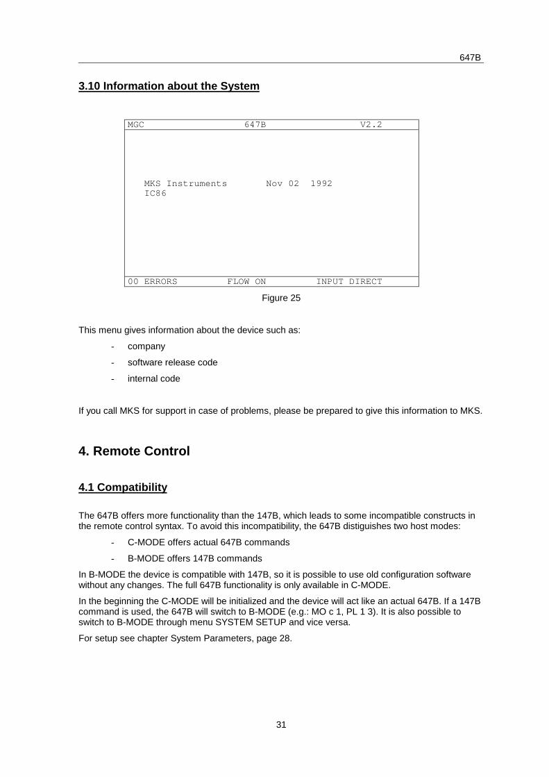
3.10 Information about the System
MGC 647B V2.2
MKS Instruments Nov 02 1992 IC86
00 ERRORS FLOW ON INPUT DIRECT
Figure 25
This menu gives information about the device such as:
- company
- software release code
- internal code
If you call MKS for support in case of problems, please be prepared to give this information to MKS.
4. Remote Control
4.1 Compatibility
The 647B offers more functionality than the 147B, which leads to some incompatible constructs inthe remote control syntax. To avoid this incompatibility, the 647B distiguishes two host modes:
- C-MODE offers actual 647B commands
- B-MODE offers 147B commands
In B-MODE the device is compatible with 147B, so it is possible to use old configuration softwarewithout any changes. The full 647B functionality is only available in C-MODE.
In the beginning the C-MODE will be initialized and the device will act like an actual 647B. If a 147Bcommand is used, the 647B will switch to B-MODE (e.g.: MO c 1, PL 1 3). It is also possible toswitch to B-MODE through menu SYSTEM SETUP and vice versa.
For setup see chapter System Parameters, page 28.
647B
32
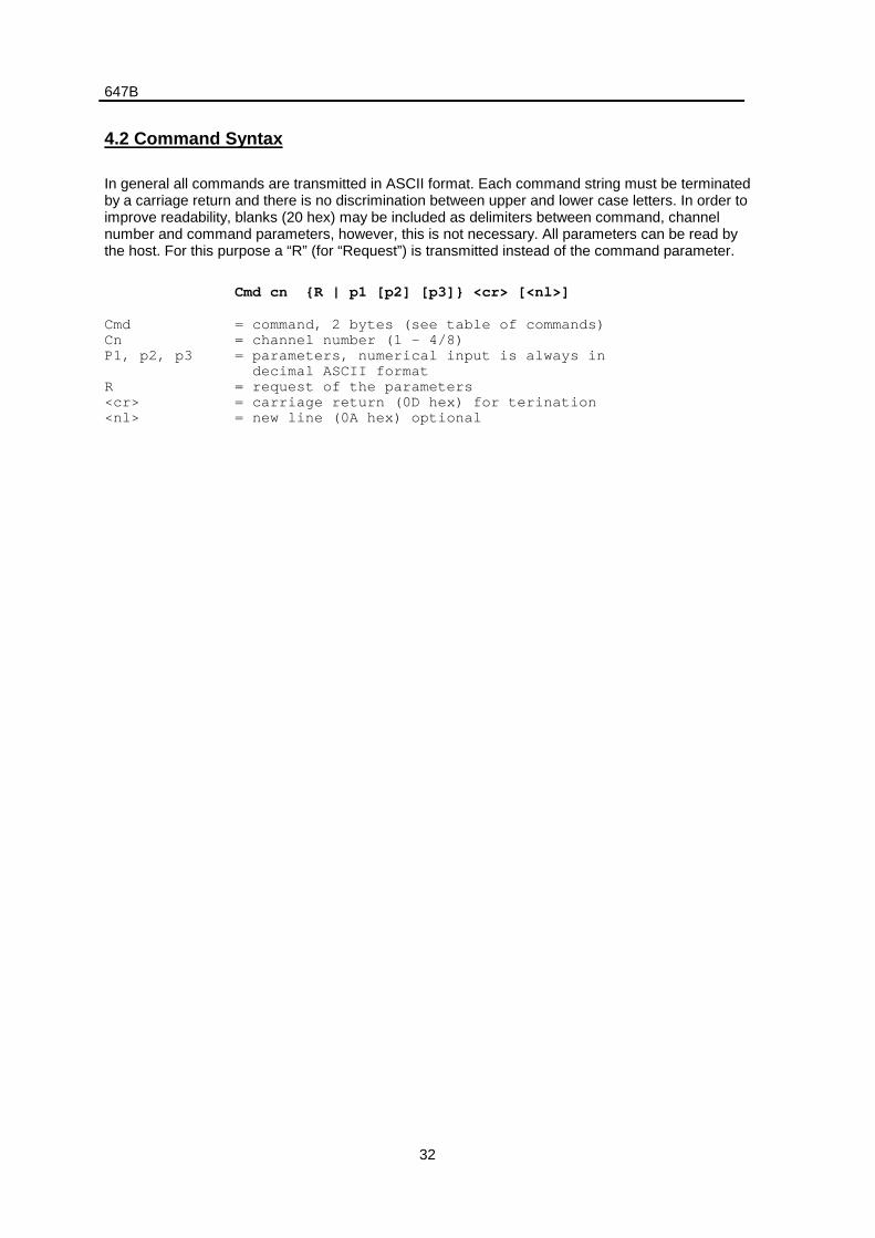
4.2 Command Syntax
In general all commands are transmitted in ASCII format. Each command string must be terminatedby a carriage return and there is no discrimination between upper and lower case letters. In order toimprove readability, blanks (20 hex) may be included as delimiters between command, channelnumber and command parameters, however, this is not necessary. All parameters can be read bythe host. For this purpose a “R” (for “Request”) is transmitted instead of the command parameter.
Cmd cn {R | p1 [p2] [p3]} <cr> [<nl>]
CmdCnP1, p2, p3
R<cr><nl>
= command, 2 bytes (see table of commands)= channel number (1 – 4/8)= parameters, numerical input is always in decimal ASCII format= request of the parameters= carriage return (0D hex) for terination= new line (0A hex) optional
647B
33
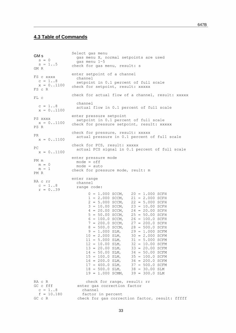
4.3 Table of Commands
GM s s = 0 s = 1..5GM R
FS c xxxx c = 1..8 x = 0..1100FS c R
FL c
c = 1..8 x = 0..1100
PS xxxx x = 0..1100PS R
PR x = 0..1100
PC x = 0..1100
PM m m = 0 m = 1PM R
RA c rr c = 1..8 r = 0..39
Select gas menu gas menu X, normal setpoints are used gas menu 1-5check for gas menu, result: s
enter setpoint of a channel channel setpoint in 0.1 percent of full scalecheck for setpoint, result: xxxxx
check for actual flow of a channel, result: xxxxx
channel actual flow in 0.1 percent of full scale
enter pressure setpoint setpoint in 0.1 percent of full scalecheck for pressure setpoint, result: xxxxx
check for pressure, result: xxxxx actual pressure in 0.1 percent of full scale
check for PCS, result: xxxxx actual PCS signal in 0.1 percent of full scale
enter pressure mode mode = off mode = autocheck for pressure mode, reult: m
enter range channel range code:
RA c R
0 = 1.000 SCCM, 20 = 1.000 SCFH 1 = 2.000 SCCM, 21 = 2.000 SCFH 2 = 5.000 SCCM, 22 = 5.000 SCFH 3 = 10.00 SCCM, 23 = 10.00 SCFH 4 = 20.00 SCCM, 24 = 20.00 SCFH 5 = 50.00 SCCM, 25 = 50.00 SCFH 6 = 100.0 SCCM, 26 = 100.0 SCFH 7 = 200.0 SCCM, 27 = 200.0 SCFH 8 = 500.0 SCCM, 28 = 500.0 SCFH 9 = 1.000 SLM, 29 = 1.000 SCFM10 = 2.000 SLM, 30 = 2.000 SCFM11 = 5.000 SLM, 31 = 5.000 SCFM12 = 10.00 SLM, 32 = 10.00 SCFM13 = 20.00 SLM, 33 = 20.00 SCFM14 = 50.00 SLM, 34 = 50.00 SCFM15 = 100.0 SLM, 35 = 100.0 SCFM16 = 200.0 SLM, 36 = 200.0 SCFM17 = 400.0 SLM, 37 = 500.0 SCFM18 = 500.0 SLM, 38 = 30.00 SLM19 = 1.000 SCMM, 39 = 300.0 SLM
check for range, result: rrGC c fff c = 1..8 f = 10.180GC c R
enter gas correction factor channel factor in percentcheck for gas correction factor, result: fffff
647B
34
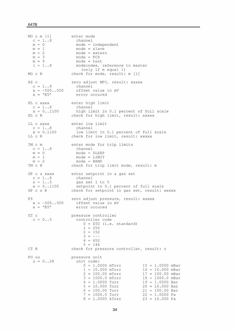
MO c m [i] c = 1..8 m = 0 m = 1 m = 2 m = 3 m = 9 i = 1..8
MO c R
AZ c c = 1..8 x = -500..500 x = “E5”
HL c xxxx c = 1..8 x = 0..1100HL c R
LL c xxxx c = 1..8 x = 0.1100LL c R
TM c m c = 1..8 m = 0 m = 1 m = 2TM c R
GP c s xxxx c = 1..8 s = 1..5 x = 0..1100GP c s R
PZ x = -500..500 x = “E5”
GT c c = 0..5
CT R
enter mode channel mode = independent mode = slave mode = extern mode = PCS mode = test modeindex, reference to master (only if m equal 1)check for mode, result: m [i]
zero adjust MFC, result: xxxxx channel offset value in mV error occured
enter high limit channel high limit in 0.1 percent of full scalecheck for high limit, result: xxxxx
enter low limit channel low limit in 0.1 percent of full scalecheck for low limit, result: xxxxx
enter mode for trip limits channel mode = SLEEP mode = LIMIT mode = BANDcheck for trip limit mode, result: m
enter setpoint in a gas set channel gas set 1 to 5 setpoint in 0.1 percent of full scalecheck for setpoint in gas set, result: xxxxx
zero adjust pressure, result: xxxxx offset value in mV error occured
pressure controller controller code 0 = STD (i.e. standard) 1 = 250 2 = 152 3 = --- 4 = 652 5 = 146check for pressure controller, result: c
PU uu u = 0..28
pressure unit unit code: 0 = 1.0000 mTorr 15 = 1.0000 mBar 1 = 10.000 mTorr 16 = 10.000 mBar 2 = 100.00 mTorr 17 = 100.00 mBar 3 = 1000.0 mTorr 18 = 1000.0 mBar 4 = 1.0000 Torr 19 = 1.0000 Bar 5 = 10.000 Torr 20 = 10.000 Bar 6 = 100.00 Torr 21 = 100.00 Bar 7 = 1000.0 Torr 22 = 1.0000 Pa 8 = 1.0000 kTorr 23 = 10.000 Pa
647B
35
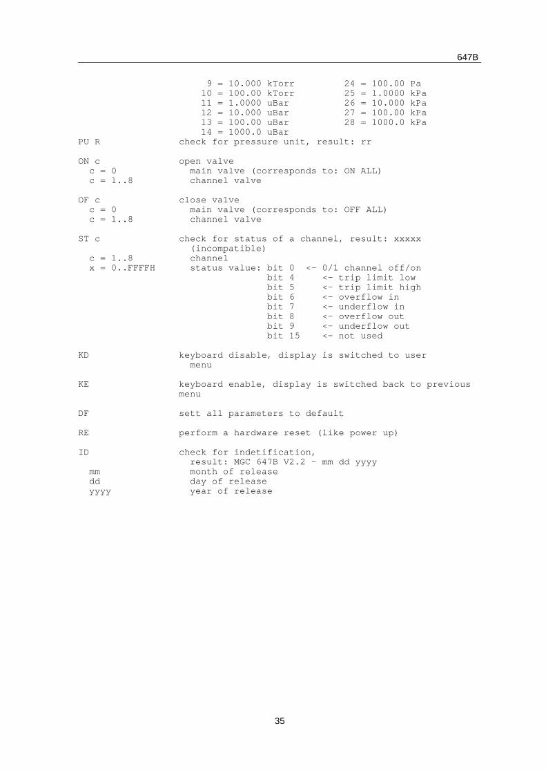
PU R
ON c c = 0 c = 1..8
OF c c = 0 c = 1..8
ST c
c = 1..8 x = 0..FFFFH
KD
KE
DF
RE
ID
mm dd yyyy
9 = 10.000 kTorr 24 = 100.00 Pa 10 = 100.00 kTorr 25 = 1.0000 kPa 11 = 1.0000 uBar 26 = 10.000 kPa 12 = 10.000 uBar 27 = 100.00 kPa 13 = 100.00 uBar 28 = 1000.0 kPa 14 = 1000.0 uBarcheck for pressure unit, result: rr
open valve main valve (corresponds to: ON ALL) channel valve
close valve main valve (corresponds to: OFF ALL) channel valve
check for status of a channel, result: xxxxx (incompatible) channel status value: bit 0 <- 0/1 channel off/on bit 4 <- trip limit low bit 5 <- trip limit high bit 6 <- overflow in bit 7 <- underflow in bit 8 <- overflow out bit 9 <- underflow out bit 15 <- not used
keyboard disable, display is switched to user menu
keyboard enable, display is switched back to previousmenu
sett all parameters to default
perform a hardware reset (like power up)
check for indetification, result: MGC 647B V2.2 – mm dd yyyy month of release day of release year of release
647B
36
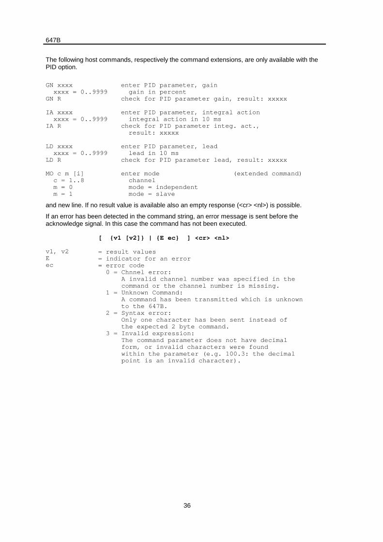
The following host commands, respectively the command extensions, are only available with thePID option.
GN xxxx xxxx = 0..9999GN R
IA xxxx xxxx = 0..9999IA R
LD xxxx xxxx = 0..9999LD R
MO c m [i] c = 1..8 m = 0 m = 1
enter PID parameter, gain gain in percentcheck for PID parameter gain, result: xxxxx
enter PID parameter, integral action integral action in 10 mscheck for PID parameter integ. act., result: xxxxx
enter PID parameter, lead lead in 10 mscheck for PID parameter lead, result: xxxxx
enter mode (extended command) channel mode = independent mode = slave
and new line. If no result value is available also an empty response (<cr> <nl>) is possible.
If an error has been detected in the command string, an error message is sent before theacknowledge signal. In this case the command has not been executed.
v1, v2Eec
[ {v1 [v2]} | {E ec} ] <cr> <nl>
= result values= indicator for an error= error code 0 = Chnnel error: A invalid channel number was specified in the command or the channel number is missing. 1 = Unknown Command: A command has been transmitted which is unknown to the 647B. 2 = Syntax error: Only one character has been sent instead of the expected 2 byte command. 3 = Invalid expression: The command parameter does not have decimal form, or invalid characters were found within the parameter (e.g. 100.3: the decimal point is an invalid character).

647B
37
<cr><nl>
4 = Invalid value: The transmitted parameter is outside the parameter range (e.g. 1200 is outside the range of a set point) 5 = Autozero error: There was a trial to set the zero offset of an active channel. Before setting the zero offset, either the channel (OF #) or the gas (OF 0) has to be switched off.
= carriage return (0D hex) for termination= new line (0A hex)
647B
38
5. Application of the 647B
5.1 Mass Flow Controllers
The mass flow controllers must have a linear DC voltage output of 0 – 5 V. The input impedancemust not be lower than 1 MOhms. Some mass flow controllers of other manufacturers can bedamaged by a constant set point < 0 V. Other possible symptoms are undesired oscillations, whenthe setpoint is varied, or disturbances of the regulation loop.
To operate mass flow controllers it is important, that the allowed maximum of input signals are notexceeded. The mass flow controllers must have a linear DC voltage input and output of 0 – 5 V.MKS mass flow controllers types 0258A/B/C, 0358B/C , 179A can be operated with the connectorcables for MKS mass flow controllers types 259, 1259, 2259, 1159, 1179A, 2179A, 1479A, 1359,1559 and 2159.
647B
39
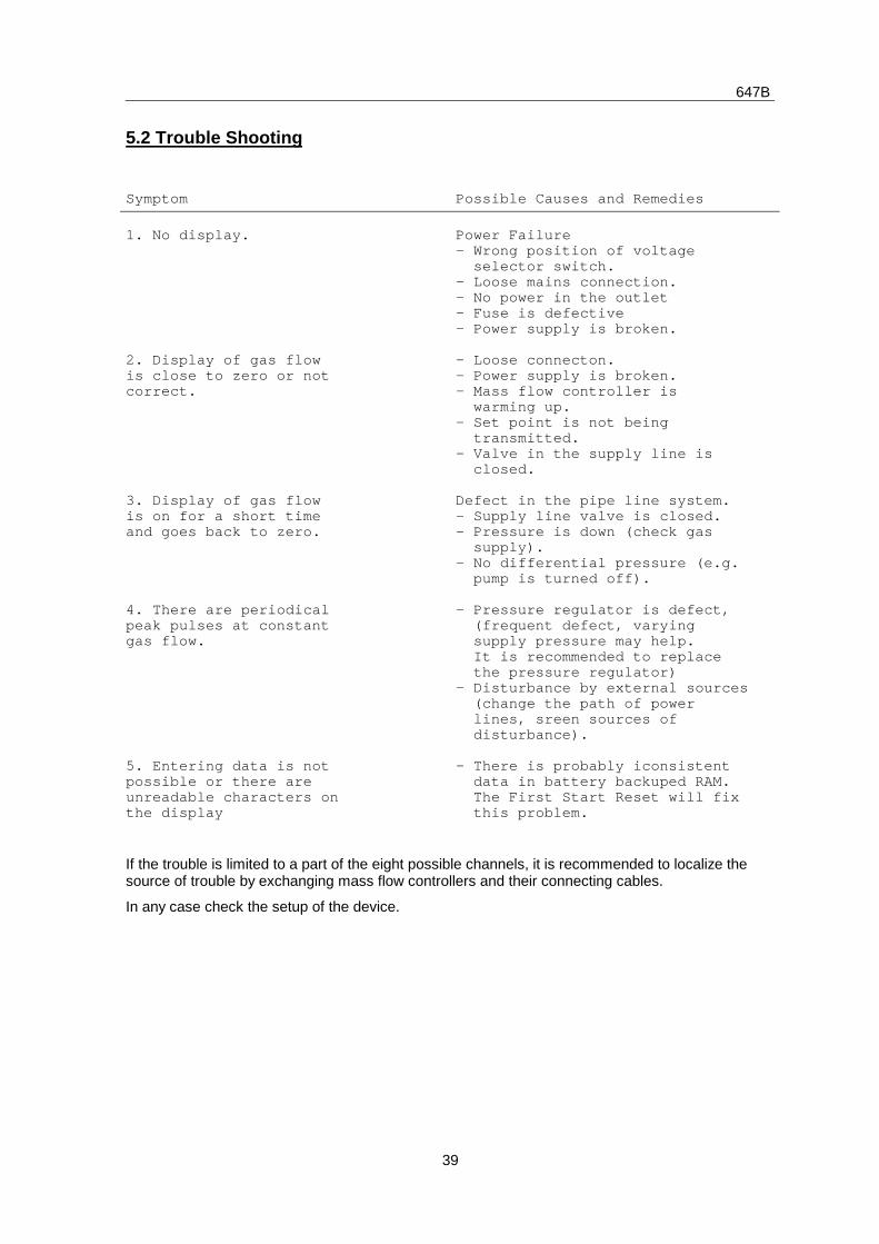
5.2 Trouble Shooting
Symptom Possible Causes and Remedies
1. No display.
2. Display of gas flowis close to zero or notcorrect.
3. Display of gas flowis on for a short timeand goes back to zero.
4. There are periodicalpeak pulses at constantgas flow.
5. Entering data is notpossible or there areunreadable characters onthe display
Power Failure- Wrong position of voltage selector switch.- Loose mains connection.- No power in the outlet– Fuse is defective– Power supply is broken.
- Loose connecton.– Power supply is broken.– Mass flow controller is warming up.– Set point is not being transmitted.– Valve in the supply line is closed.
Defect in the pipe line system.– Supply line valve is closed.– Pressure is down (check gas supply).– No differential pressure (e.g. pump is turned off).
- Pressure regulator is defect, (frequent defect, varying supply pressure may help. It is recommended to replace the pressure regulator)– Disturbance by external sources (change the path of power lines, sreen sources of disturbance).
– There is probably iconsistent data in battery backuped RAM. The First Start Reset will fix this problem.
If the trouble is limited to a part of the eight possible channels, it is recommended to localize thesource of trouble by exchanging mass flow controllers and their connecting cables.
In any case check the setup of the device.
647B
40
6. Pin Assignment of rear connectors
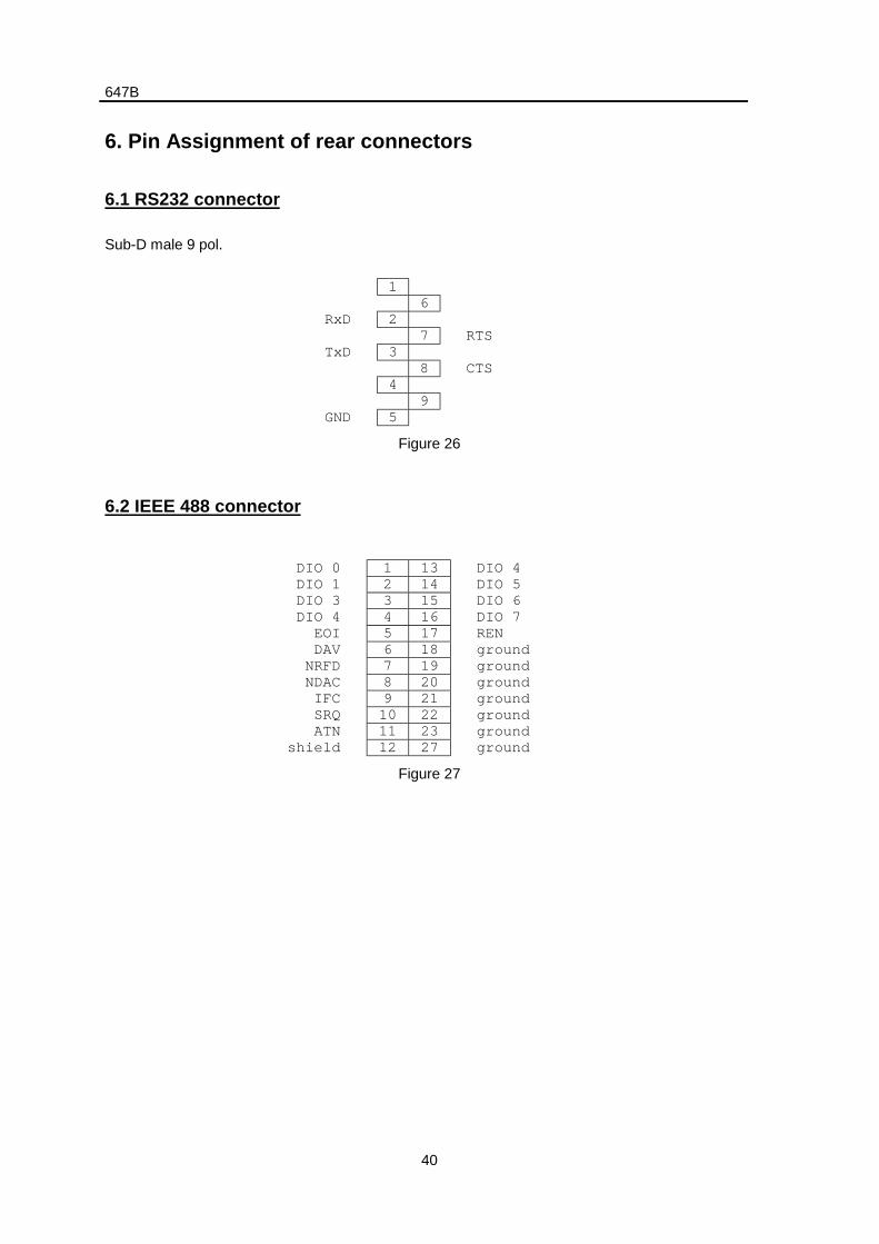
6.1 RS232 connector
Sub-D male 9 pol.
16
RxD 27 RTS
TxD 38 CTS
49
GND 5
Figure 26
6.2 IEEE 488 connector
DIO 0 1 13 DIO 4DIO 1 2 14 DIO 5DIO 3 3 15 DIO 6DIO 4 4 16 DIO 7
EOI 5 17 RENDAV 6 18 ground
NRFD 7 19 groundNDAC 8 20 groundIFC 9 21 groundSRQ 10 22 groundATN 11 23 ground
shield 12 27 ground
Figure 27
647B
41
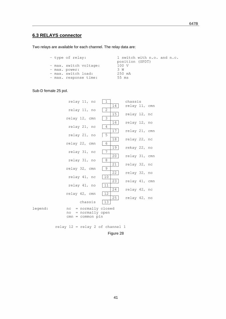
6.3 RELAYS connector
Two relays are available for each channel. The relay data are:
- type of relay:
- max. switch voltage:- max. power:– max. switch load:- max. response time:
1 switch with n.o. and n.c.position (SPDT)100 V3 W250 mA55 ms
Sub-D female 25 pol.
relay 11, nc 1 chassis14 relay 11, cmn
relay 11, no 215 relay 12, nc
relay 12, cmn 316 relay 12, no
relay 21, nc 417 relay 21, cmn
relay 21, no 518 relay 22, nc
relay 22, cmn 619 rekay 22, no
relay 31, nc 720 relay 31, cmn
relay 31, no 821 relay 32, nc
relay 32, cmn 922 relay 32, no
relay 41, nc 1023 relay 41, cmn
relay 41, no 1124 relay 42, nc
relay 42, cmn 1225 relay 42, no
chassis 13
legend: nc = normally closed no = normally open cmn = common pin
relay 12 = relay 2 of channel 1
Figure 28
647B
42
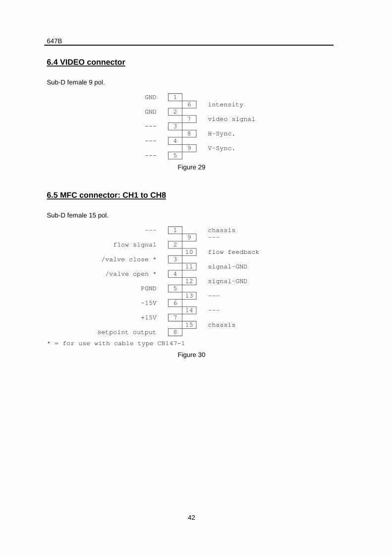
6.4 VIDEO connector
Sub-D female 9 pol.
GND 16 intensity
GND 27 video signal
--- 38 H-Sync.
--- 49 V-Sync.
--- 5
Figure 29
6.5 MFC connector: CH1 to CH8
Sub-D female 15 pol.
--- 1 chassis9 ---
flow signal 210 flow feedback
/valve close * 311 signal-GND
/valve open * 412 signal-GND
PGND 513 ---
-15V 614 ---
+15V 715 chassis
setpoint output 8
* = for use with cable type CB147-1
Figure 30
647B
43
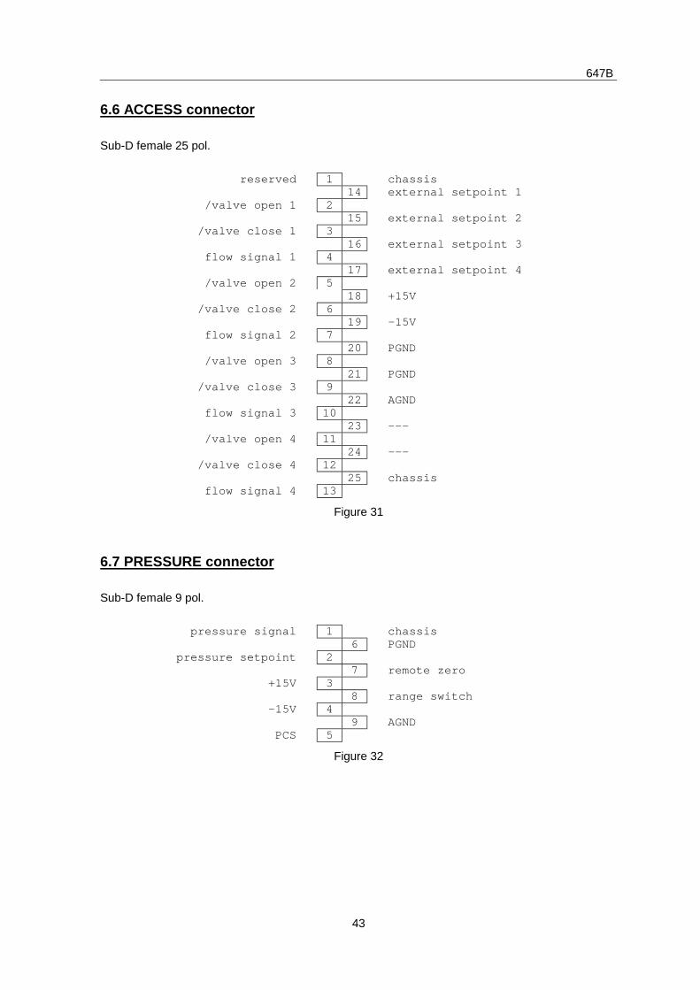
6.6 ACCESS connector
Sub-D female 25 pol.
reserved 1 chassis14 external setpoint 1
/valve open 1 215 external setpoint 2
/valve close 1 316 external setpoint 3
flow signal 1 417 external setpoint 4
/valve open 2 518 +15V
/valve close 2 619 -15V
flow signal 2 720 PGND
/valve open 3 821 PGND
/valve close 3 922 AGND
flow signal 3 1023 ---
/valve open 4 1124 ---
/valve close 4 1225 chassis
flow signal 4 13
Figure 31
6.7 PRESSURE connector
Sub-D female 9 pol.
pressure signal 1 chassis6 PGND
pressure setpoint 27 remote zero
+15V 38 range switch
-15V 49 AGND
PCS 5
Figure 32
647B
44
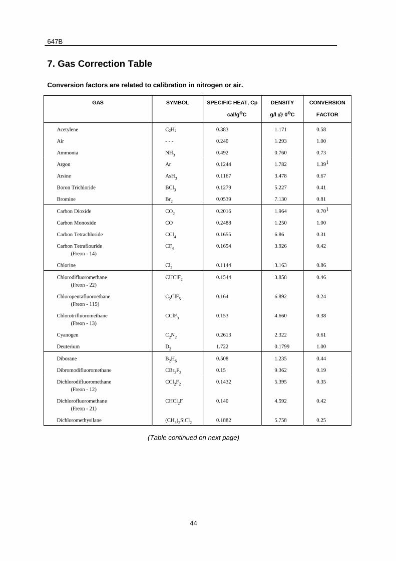
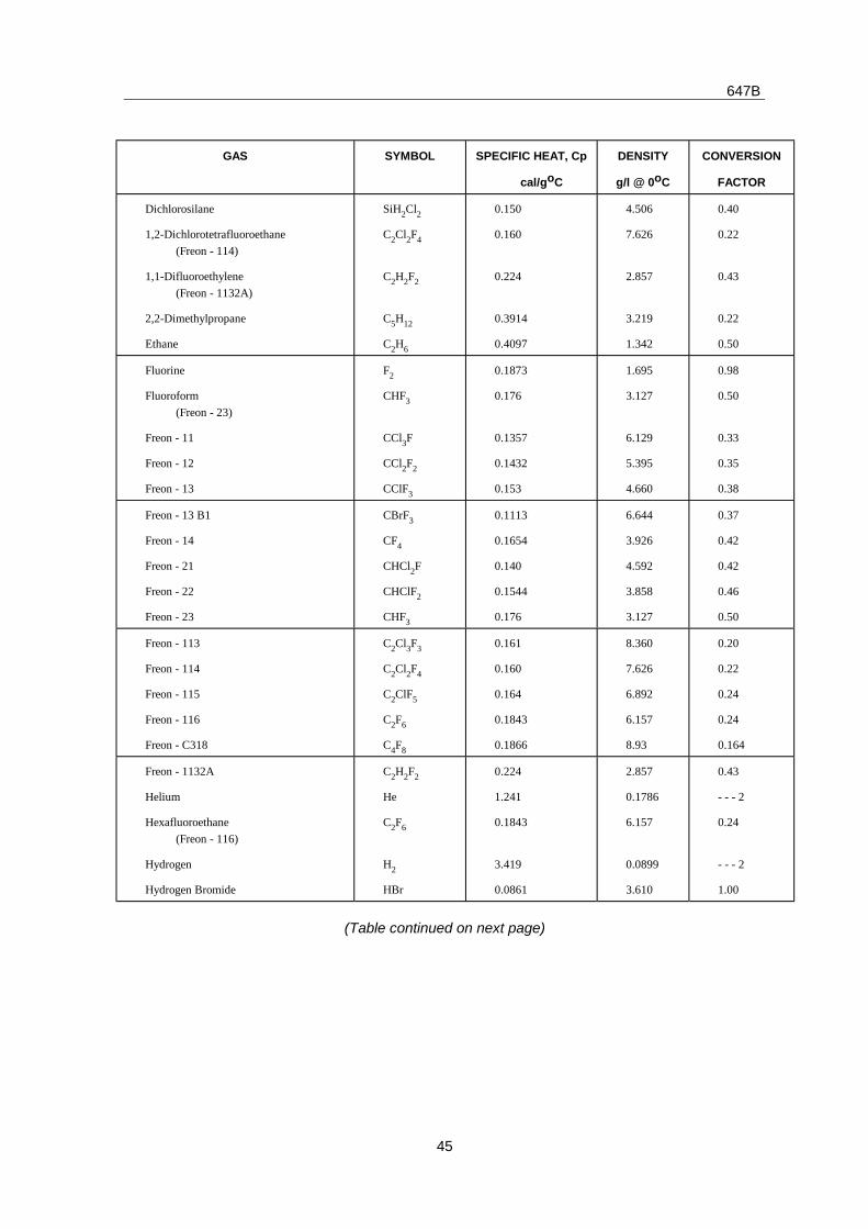
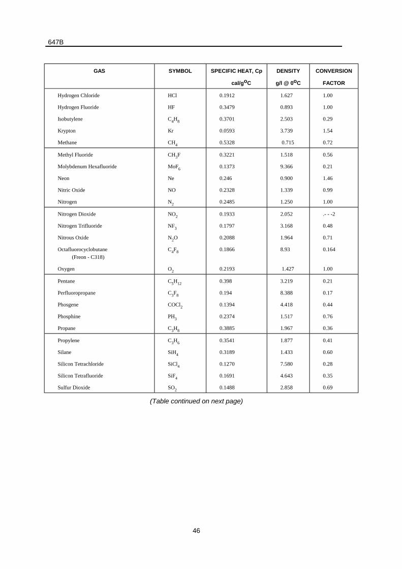
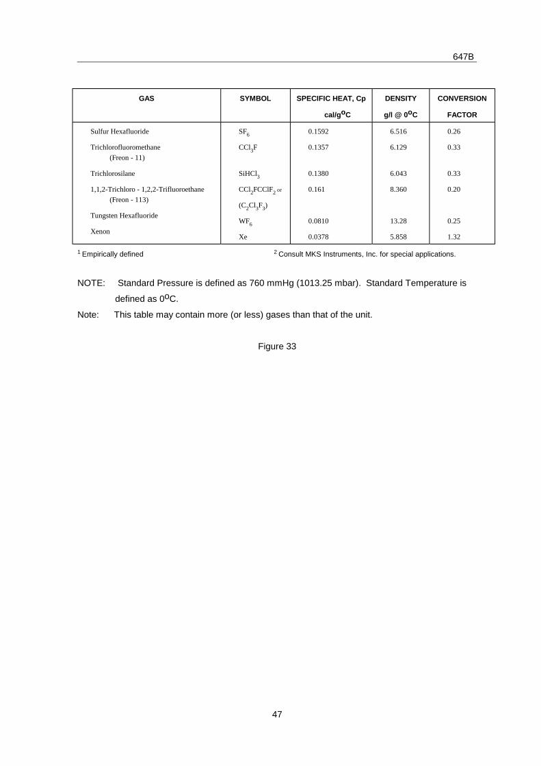
7. Gas Correction Table
Conversion factors are related to calibration in nitrogen or air.
GAS SYMBOL SPECIFIC HEAT, Cp
cal/goC
DENSITY
g/l @ 0oC
CONVERSION
FACTOR
Acetylene
Air
Ammonia
C2H2
- - -
NH3
0.383
0.240
0.492
1.171
1.293
0.760
0.58
1.00
0.73
Argon
Arsine
Boron Trichloride
Bromine
Ar
AsH3
BCl3
Br2
0.1244
0.1167
0.1279
0.0539
1.782
3.478
5.227
7.130
1.391
0.67
0.41
0.81
Carbon Dioxide
Carbon Monoxide
Carbon Tetrachloride
Carbon Tetraflouride
(Freon - 14)
Chlorine
CO2
CO
CCl4
CF4
Cl2
0.2016
0.2488
0.1655
0.1654
0.1144
1.964
1.250
6.86
3.926
3.163
0.701
1.00
0.31
0.42
0.86
Chlorodifluoromethane
(Freon - 22)
Chloropentafluoroethane
(Freon - 115)
Chlorotrifluoromethane
(Freon - 13)
Cyanogen
Deuterium
CHClF2
C2ClF5
CClF3
C2N2
D2
0.1544
0.164
0.153
0.2613
1.722
3.858
6.892
4.660
2.322
0.1799
0.46
0.24
0.38
0.61
1.00
Diborane
Dibromodifluoromethane
B2H6
CBr2F2
0.508
0.15
1.235
9.362
0.44
0.19
Dichlorodifluoromethane
(Freon - 12)
Dichlorofluoromethane
(Freon - 21)
Dichloromethysilane
CCl2F2
CHCl2F
(CH3)2SiCl2
0.1432
0.140
0.1882
5.395
4.592
5.758
0.35
0.42
0.25
(Table continued on next page)
647B
45
GAS SYMBOL SPECIFIC HEAT, Cp
cal/goC
DENSITY
g/l @ 0oC
CONVERSION
FACTOR
Dichlorosilane
1,2-Dichlorotetrafluoroethane
(Freon - 114)
1,1-Difluoroethylene
(Freon - 1132A)
2,2-Dimethylpropane
Ethane
SiH2Cl2
C2Cl2F4
C2H2F2
C5H12
C2H6
0.150
0.160
0.224
0.3914
0.4097
4.506
7.626
2.857
3.219
1.342
0.40
0.22
0.43
0.22
0.50
Fluorine
Fluoroform
(Freon - 23)
Freon - 11
Freon - 12
Freon - 13
F2
CHF3
CCl3F
CCl2F2
CClF3
0.1873
0.176
0.1357
0.1432
0.153
1.695
3.127
6.129
5.395
4.660
0.98
0.50
0.33
0.35
0.38
Freon - 13 B1
Freon - 14
Freon - 21
Freon - 22
Freon - 23
CBrF3
CF4
CHCl2F
CHClF2
CHF3
0.1113
0.1654
0.140
0.1544
0.176
6.644
3.926
4.592
3.858
3.127
0.37
0.42
0.42
0.46
0.50
Freon - 113
Freon - 114
Freon - 115
Freon - 116
Freon - C318
C2Cl3F3
C2Cl2F4
C2ClF5
C2F6
C4F8
0.161
0.160
0.164
0.1843
0.1866
8.360
7.626
6.892
6.157
8.93
0.20
0.22
0.24
0.24
0.164
Freon - 1132A
Helium
Hexafluoroethane
(Freon - 116)
Hydrogen
Hydrogen Bromide
C2H2F2
He
C2F6
H2
HBr
0.224
1.241
0.1843
3.419
0.0861
2.857
0.1786
6.157
0.0899
3.610
0.43
- - - 2
0.24
- - - 2
1.00
(Table continued on next page)
647B
46
GAS SYMBOL SPECIFIC HEAT, Cp
cal/goC
DENSITY
g/l @ 0oC
CONVERSION
FACTOR
Hydrogen Chloride
Hydrogen Fluoride
Isobutylene
Krypton
Methane
HCl
HF
C4H8
Kr
CH4
0.1912
0.3479
0.3701
0.0593
0.5328
1.627
0.893
2.503
3.739
0.715
1.00
1.00
0.29
1.54
0.72
Methyl Fluoride
Molybdenum Hexafluoride
Neon
Nitric Oxide
Nitrogen
CH3F
MoF6
Ne
NO
N2
0.3221
0.1373
0.246
0.2328
0.2485
1.518
9.366
0.900
1.339
1.250
0.56
0.21
1.46
0.99
1.00
Nitrogen Dioxide
Nitrogen Trifluoride
Nitrous Oxide
Octafluorocyclobutane
(Freon - C318)
Oxygen
NO2
NF3
N2O
C4F8
O2
0.1933
0.1797
0.2088
0.1866
0.2193
2.052
3.168
1.964
8.93
1.427
.- - -2
0.48
0.71
0.164
1.00
Pentane
Perfluoropropane
Phosgene
Phosphine
Propane
C5H12
C3F8
COCl2
PH3
C3H8
0.398
0.194
0.1394
0.2374
0.3885
3.219
8.388
4.418
1.517
1.967
0.21
0.17
0.44
0.76
0.36
Propylene
Silane
Silicon Tetrachloride
Silicon Tetrafluoride
Sulfur Dioxide
C3H6
SiH4
SiCl4
SiF4
SO2
0.3541
0.3189
0.1270
0.1691
0.1488
1.877
1.433
7.580
4.643
2.858
0.41
0.60
0.28
0.35
0.69
(Table continued on next page)
647B
47
GAS SYMBOL SPECIFIC HEAT, Cp
cal/goC
DENSITY
g/l @ 0oC
CONVERSION
FACTOR
Sulfur Hexafluoride
Trichlorofluoromethane
(Freon - 11)
Trichlorosilane
1,1,2-Trichloro - 1,2,2-Trifluoroethane
(Freon - 113)
Tungsten Hexafluoride
Xenon
SF6
CCl3F
SiHCl3
CCl2FCClF2 or
(C2Cl3F3)
WF6
Xe
0.1592
0.1357
0.1380
0.161
0.0810
0.0378
6.516
6.129
6.043
8.360
13.28
5.858
0.26
0.33
0.33
0.20
0.25
1.32
1 Empirically defined 2 Consult MKS Instruments, Inc. for special applications.
NOTE: Standard Pressure is defined as 760 mmHg (1013.25 mbar). Standard Temperature is
defined as 0oC.
Note: This table may contain more (or less) gases than that of the unit.
Figure 33
647B
48
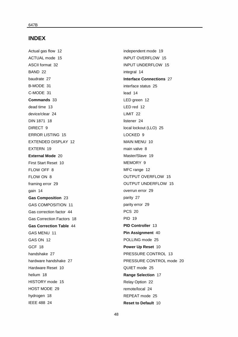
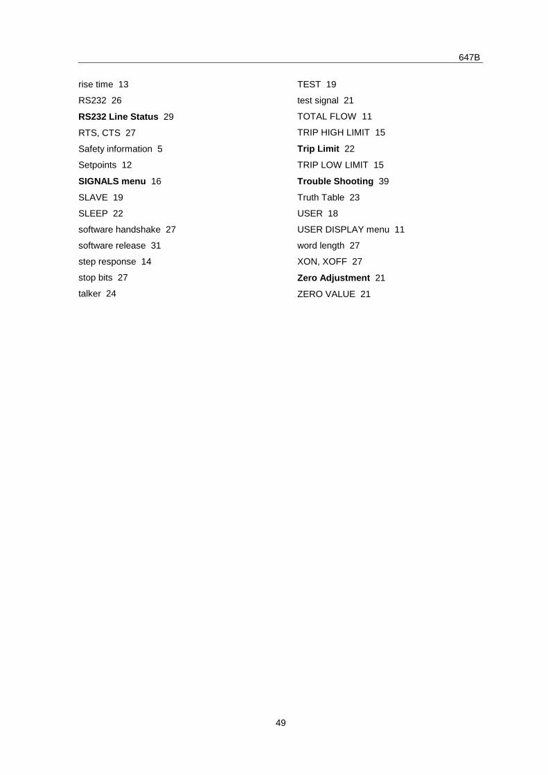
INDEX
Actual gas flow 12
ACTUAL mode 15
ASCII format 32
BAND 22
baudrate 27
B-MODE 31
C-MODE 31
Commands 33
dead time 13
device/clear 24
DIN 1871 18
DIRECT 9
ERROR LISTING 15
EXTENDED DISPLAY 12
EXTERN 19
External Mode 20
First Start Reset 10
FLOW OFF 8
FLOW ON 8
framing error 29
gain 14
Gas Composition 23
GAS COMPOSITION 11
Gas correction factor 44
Gas Correction Factors 18
Gas Correction Table 44
GAS MENU 11
GAS ON 12
GCF 18
handshake 27
hardware handshake 27
Hardware Reset 10
helium 18
HISTORY mode 15
HOST MODE 29
hydrogen 18
IEEE 488 24
independent mode 19
INPUT OVERFLOW 15
INPUT UNDERFLOW 15
integral 14
Interface Connections 27
interface status 25
lead 14
LED green 12
LED red 12
LIMIT 22
listener 24
local lockout (LLO) 25
LOCKED 9
MAIN MENU 10
main valve 8
Master/Slave 19
MEMORY 9
MFC range 12
OUTPUT OVERFLOW 15
OUTPUT UNDERFLOW 15
overrun error 29
parity 27
parity error 29
PCS 20
PID 19
PID Controller 13
Pin Assignment 40
POLLING mode 25
Power Up Reset 10
PRESSURE CONTROL 13
PRESSURE CONTROL mode 20
QUIET mode 25
Range Selection 17
Relay Option 22
remote/local 24
REPEAT mode 25
Reset to Default 10
647B
49
rise time 13
RS232 26
RS232 Line Status 29
RTS, CTS 27
Safety information 5
Setpoints 12
SIGNALS menu 16
SLAVE 19
SLEEP 22
software handshake 27
software release 31
step response 14
stop bits 27
talker 24
TEST 19
test signal 21
TOTAL FLOW 11
TRIP HIGH LIMIT 15
Trip Limit 22
TRIP LOW LIMIT 15
Trouble Shooting 39
Truth Table 23
USER 18
USER DISPLAY menu 11
word length 27
XON, XOFF 27
Zero Adjustment 21
ZERO VALUE 21
647B
50
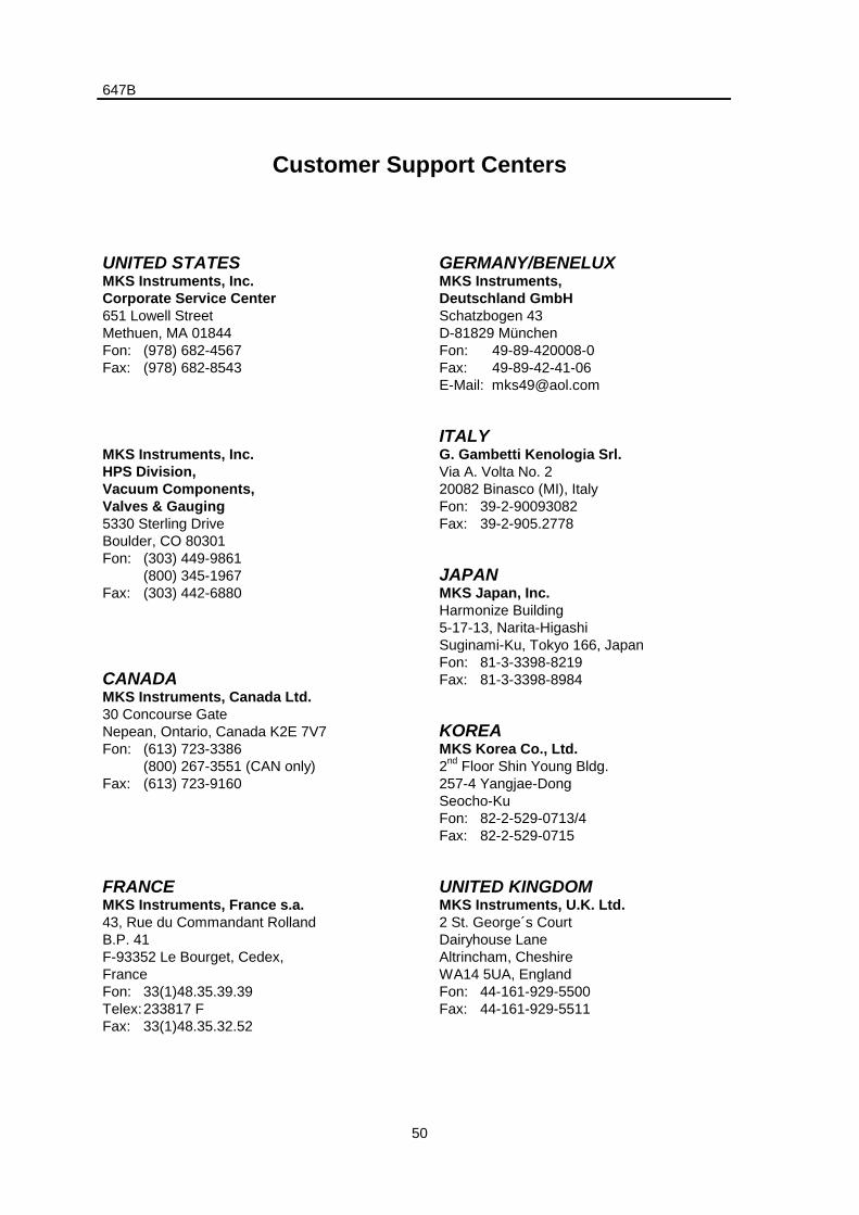
Customer Support Centers
UNITED STATESMKS Instruments, Inc.Corporate Service Center651 Lowell StreetMethuen, MA 01844Fon: (978) 682-4567Fax: (978) 682-8543
MKS Instruments, Inc.HPS Division,Vacuum Components,Valves & Gauging5330 Sterling DriveBoulder, CO 80301Fon: (303) 449-9861
(800) 345-1967Fax: (303) 442-6880
CANADAMKS Instruments, Canada Ltd.30 Concourse GateNepean, Ontario, Canada K2E 7V7Fon: (613) 723-3386
(800) 267-3551 (CAN only)Fax: (613) 723-9160
FRANCEMKS Instruments, France s.a.43, Rue du Commandant RollandB.P. 41F-93352 Le Bourget, Cedex,FranceFon: 33(1)48.35.39.39Telex:233817 FFax: 33(1)48.35.32.52
GERMANY/BENELUXMKS Instruments,Deutschland GmbHSchatzbogen 43D-81829 MünchenFon: 49-89-420008-0Fax: 49-89-42-41-06E-Mail: [email protected]
ITALYG. Gambetti Kenologia Srl.Via A. Volta No. 220082 Binasco (MI), ItalyFon: 39-2-90093082Fax: 39-2-905.2778
JAPANMKS Japan, Inc.Harmonize Building5-17-13, Narita-HigashiSuginami-Ku, Tokyo 166, JapanFon: 81-3-3398-8219Fax: 81-3-3398-8984
KOREAMKS Korea Co., Ltd.2nd Floor Shin Young Bldg.257-4 Yangjae-DongSeocho-KuFon: 82-2-529-0713/4Fax: 82-2-529-0715
UNITED KINGDOMMKS Instruments, U.K. Ltd.2 St. George´s CourtDairyhouse LaneAltrincham, CheshireWA14 5UA, EnglandFon: 44-161-929-5500Fax: 44-161-929-5511