Modell: HTW-SWP-O-160LIO
64
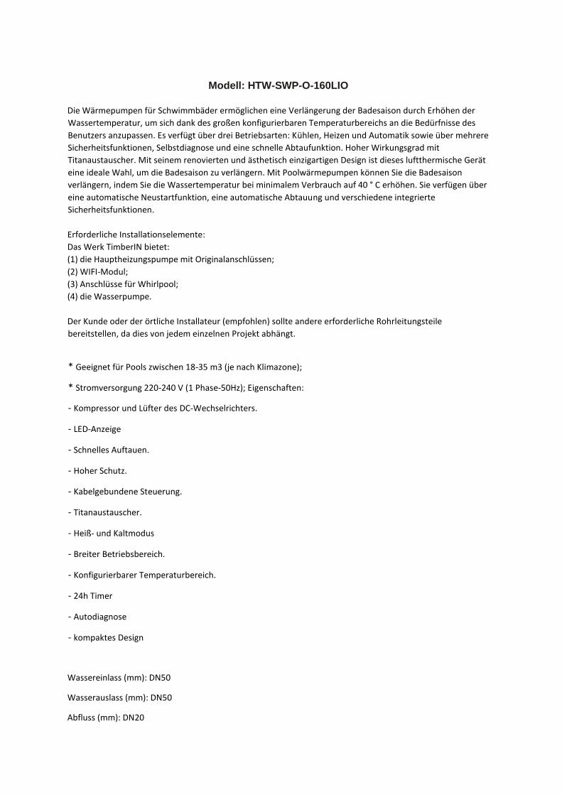
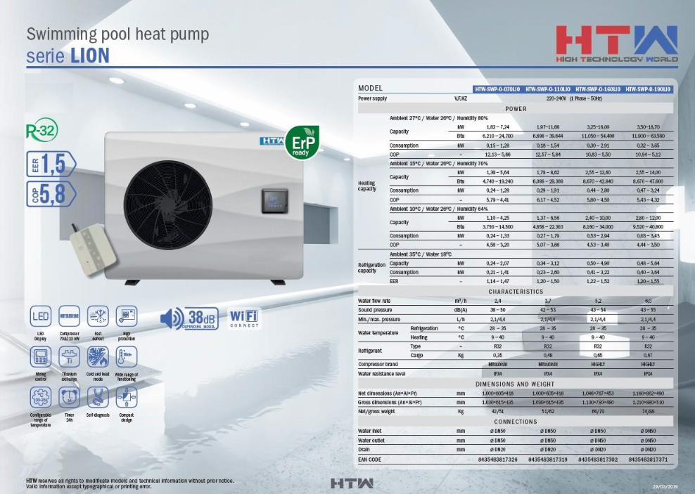
Modell: HTW-SWP-O-160LIO Die Wärmepumpen für Schwimmbäder ermöglichen eine Verlängerung der Badesaison durch Erhöhen der Wassertemperatur, um sich dank des großen konfigurierbaren Temperaturbereichs an die Bedürfnisse des Benutzers anzupassen. Es verfügt über drei Betriebsarten: Kühlen, Heizen und Automatik sowie über mehrere Sicherheitsfunktionen, Selbstdiagnose und eine schnelle Abtaufunktion. Hoher Wirkungsgrad mit Titanaustauscher. Mit seinem renovierten und ästhetisch einzigartigen Design ist dieses luftthermische Gerät eine ideale Wahl, um die Badesaison zu verlängern. Mit Poolwärmepumpen können Sie die Badesaison verlängern, indem Sie die Wassertemperatur bei minimalem Verbrauch auf 40 ° C erhöhen. Sie verfügen über eine automatische Neustartfunktion, eine automatische Abtauung und verschiedene integrierte Sicherheitsfunktionen. Erforderliche Installationselemente: Das Werk TimberIN bietet: (1) die Hauptheizungspumpe mit Originalanschlüssen; (2) WIFI-Modul; (3) Anschlüsse für Whirlpool; (4) die Wasserpumpe. Der Kunde oder der örtliche Installateur (empfohlen) sollte andere erforderliche Rohrleitungsteile bereitstellen, da dies von jedem einzelnen Projekt abhängt. * Geeignet für Pools zwischen 18-35 m3 (je nach Klimazone); * Stromversorgung 220-240 V (1 Phase-50Hz); Eigenschaften: - Kompressor und Lüfter des DC-Wechselrichters. - LED-Anzeige - Schnelles Auftauen. - Hoher Schutz. - Kabelgebundene Steuerung. - Titanaustauscher. - Heiß- und Kaltmodus - Breiter Betriebsbereich. - Konfigurierbarer Temperaturbereich. - 24h Timer - Autodiagnose - kompaktes Design Wassereinlass (mm): DN50 Wasserauslass (mm): DN50 Abfluss (mm): DN20
Transcript of Modell: HTW-SWP-O-160LIO
Modell: HTW-SWP-O-160LIO
Die Wärmepumpen für Schwimmbäder ermöglichen eine Verlängerung der Badesaison durch Erhöhen der
Wassertemperatur, um sich dank des großen konfigurierbaren Temperaturbereichs an die Bedürfnisse des
Benutzers anzupassen. Es verfügt über drei Betriebsarten: Kühlen, Heizen und Automatik sowie über mehrere
Sicherheitsfunktionen, Selbstdiagnose und eine schnelle Abtaufunktion. Hoher Wirkungsgrad mit
Titanaustauscher. Mit seinem renovierten und ästhetisch einzigartigen Design ist dieses luftthermische Gerät
eine ideale Wahl, um die Badesaison zu verlängern. Mit Poolwärmepumpen können Sie die Badesaison
verlängern, indem Sie die Wassertemperatur bei minimalem Verbrauch auf 40 ° C erhöhen. Sie verfügen über
eine automatische Neustartfunktion, eine automatische Abtauung und verschiedene integrierte
Sicherheitsfunktionen.
Erforderliche Installationselemente:
Das Werk TimberIN bietet:
(1) die Hauptheizungspumpe mit Originalanschlüssen;
(2) WIFI-Modul;
(3) Anschlüsse für Whirlpool;
(4) die Wasserpumpe.
Der Kunde oder der örtliche Installateur (empfohlen) sollte andere erforderliche Rohrleitungsteile
bereitstellen, da dies von jedem einzelnen Projekt abhängt.
* Geeignet für Pools zwischen 18-35 m3 (je nach Klimazone);
* Stromversorgung 220-240 V (1 Phase-50Hz); Eigenschaften:
- Kompressor und Lüfter des DC-Wechselrichters.
- LED-Anzeige
- Schnelles Auftauen.
- Hoher Schutz.
- Kabelgebundene Steuerung.
- Titanaustauscher.
- Heiß- und Kaltmodus
- Breiter Betriebsbereich.
- Konfigurierbarer Temperaturbereich.
- 24h Timer
- Autodiagnose
- kompaktes Design
Wassereinlass (mm): DN50
Wasserauslass (mm): DN50
Abfluss (mm): DN20
OWNER’S AND
TALLATION INS MAN UAL
SWIMMING POOL HEAT PUMP
Thanks for choosing our product.
Please, read carefully this manual
before using the product.
LION
HTW - SWP - O - 070 LIO | HTW - SWP - O - 110 LIO
HTW - SWP - O - 160 LIO | HTW - SWP - O - 190 LIO

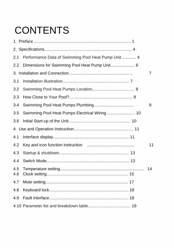
CONTENTS 1. Preface .................................................................................... 1
2. Specifications............................................................................ 4
2.1 Performance Data of Swimming Pool Heat Pump Unit............. 4
2.2 Dimensions for Swimming Pool Heat Pump Unit..................... 6
3. Installation and Connection........................................................ 7
3.1 Installation illustration.......................................................... 7
3.2 Swimming Pool Heat Pumps Location..................................... 8
3.3 How Close to Your Pool?....................................................... 8
3.4 Swimming Pool Heat Pumps Plumbing................................... 9
3.5 Swimming Pool Heat Pumps Electrical Wiring ........................ 10
3.6 Initial Start-up of the Unit...................................................... 10
4. Use and Operation Instruction.................................................... 11
4.1 Interface display.................................................................. 11
4.2 Key and icon function instruction ......................................... 11
4.3 Startup & shutdown............................................................. 13
4.4 Switch Mode........................................................................ 13
4.5 Temperature setting......................................................................... 14 4.6 Clock setting....................................................................... 15
4.7 Mute setting........................................................................ 17
4.8 Keyboard lock..................................................................... 18
4.9 Fault interface..................................................................... 18
4.10 Parameter list and breakdown table..................................... 19
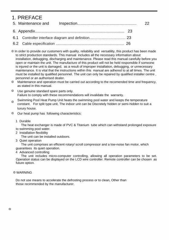
1. PREFACE
5. Maintenance and Inspection..................................................... 22
6. Appendix................................................................................ 23
6.1 Controller interface diagram and definition.................................... 23
6.2 Cable especification .................................................................... 26
In order to provide our customers with quality, reliability and versatility, this product has been made
to strict production standards. This manual includes all the necessary information about
installation, debugging, discharging and maintenance. Please read this manual carefully before you
open or maintain the unit. The manufacture of this product will not be held responsible if someone
is injured or the unit is damaged, as a result of improper installation, debugging, or unnecessary
maintenance. It is vital that the instructions within this manual are adhered to at all times. The unit
must be installed by qualified personnel. The unit can only be repaired by qualified installer centre ,
personnel or an authorised dealer. Maintenance and operation must be carried out according to the recomended time and frequency,
as stated in this manual. Use genuine standard spare parts only. Failure to comply with these recommendations will invalidate the warranty. Swimming Pool Heat Pump Unit heats the swimming pool water and keeps the temperature
constant. For split type unit, The indoor unit can be Discretely hidden or semi-hidden to suit a luxury house. Our heat pump has following characteristics:
1 Durable The heat exchanger is made of PVC & Titanium tube which can withstand prolonged exposure
to swimming pool water. 2 Installation flexibility The unit can be installed outdoors. 3 Quiet operation The unit comprises an efficient rotary/ scroll compressor and a low-noise fan motor, which
guarantees its quiet operation. 4 Advanced controlling The unit includes micro-computer controlling, allowing all operation parameters to be set. Operation status can be displayed on the LCD wire controller. Remote controller can be chosen as future option.
WARNING
Do not use means to accelerate the defrosting process or to clean, Other than
those recimmended by the manufacturer.
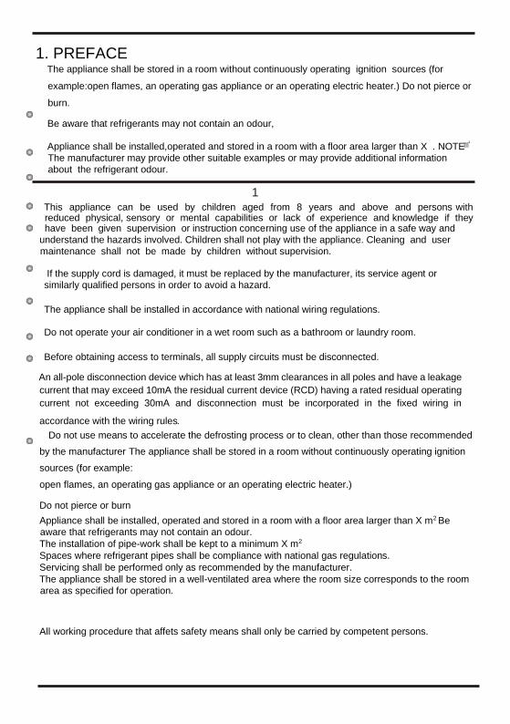
1. PREFACE
The appliance shall be stored in a room without continuously operating ignition sources (for
example:open flames, an operating gas appliance or an operating electric heater.) Do not pierce or
burn.
Be aware that refrigerants may not contain an odour,
Appliance shall be installed,operated and stored in a room with a floor area larger than X . NOTE
The manufacturer may provide other suitable examples or may provide additional information
about the refrigerant odour.
1 This appliance can be used by children aged from 8 years and above and persons with reduced physical, sensory or mental capabilities or lack of experience and knowledge if they have been given supervision or instruction concerning use of the appliance in a safe way and
understand the hazards involved. Children shall not play with the appliance. Cleaning and user
maintenance shall not be made by children without supervision.
If the supply cord is damaged, it must be replaced by the manufacturer, its service agent or
similarly qualified persons in order to avoid a hazard.
The appliance shall be installed in accordance with national wiring regulations.
Do not operate your air conditioner in a wet room such as a bathroom or laundry room.
Before obtaining access to terminals, all supply circuits must be disconnected.
An all-pole disconnection device which has at least 3mm clearances in all poles and have a leakage
current that may exceed 10mA the residual current device (RCD) having a rated residual operating
current not exceeding 30mA and disconnection must be incorporated in the fixed wiring in
accordance with the wiring rules Do not use means to accelerate the defrosting process or to clean, other than those recommended
by the manufacturer The appliance shall be stored in a room without continuously operating ignition
sources (for example: open flames, an operating gas appliance or an operating electric heater.)
Do not pierce or burn Appliance shall be installed, operated and stored in a room with a floor area larger than X m2 Be
aware that refrigerants may not contain an odour. The installation of pipe-work shall be kept to a minimum X m2 Spaces where refrigerant pipes shall be compliance with national gas regulations. Servicing shall be performed only as recommended by the manufacturer. The appliance shall be stored in a well-ventilated area where the room size corresponds to the room
area as specified for operation.
All working procedure that affets safety means shall only be carried by competent persons.

1. PREFACE
Transport of equipment containing flammable refrigerants Compliance with the transport regulations Marking of equipment using signs Compliance with local regulations Disposal of equipment using flammable refrigerants Compliance with national
regulations Storage of equipment/appliances The storage of equipment should be in accordance with the manufacturer's instructions. Storage of
packed (unsold) equipment Storage package protection should be constructed such that mechanical damage to the equipment
inside the package will not cause a leak of the refrigerant charge. The maximum number of pieces
of equipment permitted to be stored together will be determined by local regulations.
2
1. PREFACE
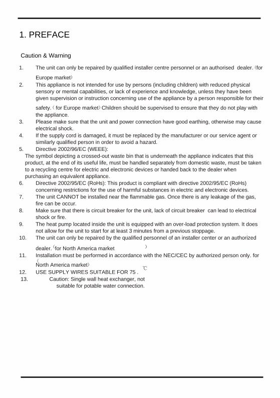
Caution & Warning
1. The unit can only be repaired by qualified installer centre personnel or an authorised dealer. for
Europe market 2. This appliance is not intended for use by persons (including children) with reduced physical
sensory or mental capabilities, or lack of experience and knowledge, unless they have been
given supervision or instruction concerning use of the appliance by a person responsible for their
safety. for Europe market Children should be supervised to ensure that they do not play with
the appliance. 3. Please make sure that the unit and power connection have good earthing, otherwise may cause
electrical shock. 4. If the supply cord is damaged, it must be replaced by the manufacturer or our service agent or
similarly qualified person in order to avoid a hazard. 5. Directive 2002/96/EC (WEEE):
The symbol depicting a crossed-out waste bin that is underneath the appliance indicates that this
product, at the end of its useful life, must be handled separately from domestic waste, must be taken
to a recycling centre for electric and electronic devices or handed back to the dealer when
purchasing an equivalent appliance. 6. Directive 2002/95/EC (RoHs): This product is compliant with directive 2002/95/EC (RoHs)
concerning restrictions for the use of harmful substances in electric and electronic devices. 7. The unit CANNOT be installed near the flammable gas. Once there is any leakage of the gas,
fire can be occur. 8. Make sure that there is circuit breaker for the unit, lack of circuit breaker can lead to electrical
shock or fire. 9. The heat pump located inside the unit is equipped with an over-load protection system. It does
not allow for the unit to start for at least 3 minutes from a previous stoppage. 10. The unit can only be repaired by the qualified personnel of an installer center or an authorized
dealer. for North America market 11. Installation must be performed in accordance with the NEC/CEC by authorized person only. for
North America market 12. USE SUPPLY WIRES SUITABLE FOR 75 . 13. Caution: Single wall heat exchanger, not
suitable for potable water connection.

4
2.SPECIFICATION
2.1 Performance data of Swimming Pool Heat Pump Unit *** REFRIGERANT : R32
UNIT HTW-SWP-O-160LIO
*Rated Heating Capacity(90Hz) kW 16.00
Btu/h 54400
*Range kW 3.25~16.00
Btu/h 11050~5440
*Rated Heating Power Input(90Hz) kW 2.91
*Range kW 0.30~2.91
*Rated Running Current Input(90Hz) A 12.60
*Range A 1.30~12.60
**Rated Heating Capacity(90Hz) kW 12.60
Btu/h 42840
**Range kW 2.55~12.60
Btu/h 8670~42840
**Rated Heating Power Input(90Hz) kW 2.80
**Range kW 0.44~2.80
**Rated Running Current Input(90Hz) A 12.17
**Range A 1.91~12.17
Power Supply 220-240V~/50Hz
Compressor Quantity 1
Compressor Rotary(HIGHLY)
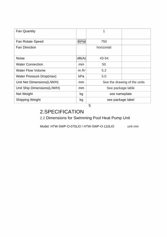
Fan Quantity 1
Fan Rotate Speed RPM 750 Fan Direction horizontal
Noise dB(A) 43-54 Water Connection mm 50 Water Flow Volume m /h3 5.2 Water Pressure Drop(max) kPa 5.0 Unit Net Dimensions(L/W/H) mm See the drawing of the units
Unit Ship Dimensions(L/W/H) mm See package lable
Net Weight kg see nameplate
Shipping Weight kg see package label
5
2.SPECIFICATION 2.2 Dimensions for Swimming Pool Heat Pump Unit
Model: HTW-SWP-O-070LIO / HTW-SWP-O-110LIO unit mm
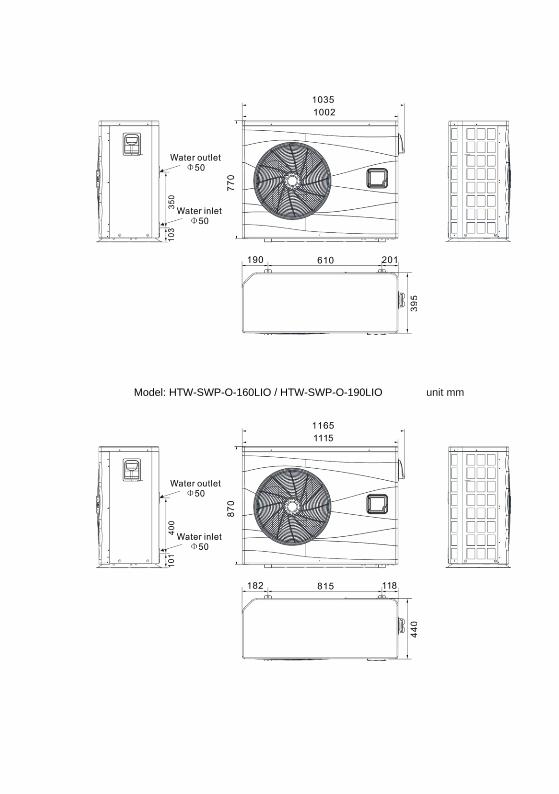
Model: HTW-SWP-O-160LIO / HTW-SWP-O-190LIO unit mm
6 .INSTALLATION AND
CONNECTION
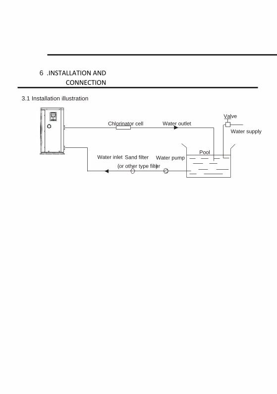
Installation illustration 3.1
Chlorinator cell Water outlet
Pool
Valve
Water supply
Water inlet Water pump Sand filter ( or other type filter )
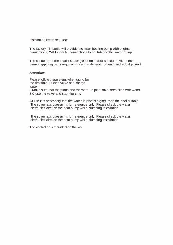
Installation items required:
The factory TimberIN will provide the main heating pump with original connections; WIFI module; connections to hot tub and the water pump.
The customer or the local installer (recommended) should provide other plumbing-piping parts required since that depends on each individual project.
Attention:
Please follow these steps when using for the first time 1.Open valve and charge water. 2.Make sure that the pump and the water-in pipe have been filled with water. 3.Close the valve and start the unit.
ATTN: It is necessary that the water-in pipe is higher than the pool surface. The schematic diagram is for reference only. Please check the water inlet/outlet label on the heat pump while plumbing installation.
The schematic diagram is for reference only. Please check the water inlet/outlet label on the heat pump while plumbing installation.
The controller is mounted on the wall

8
3.INSTALLATION AND CONNECTION
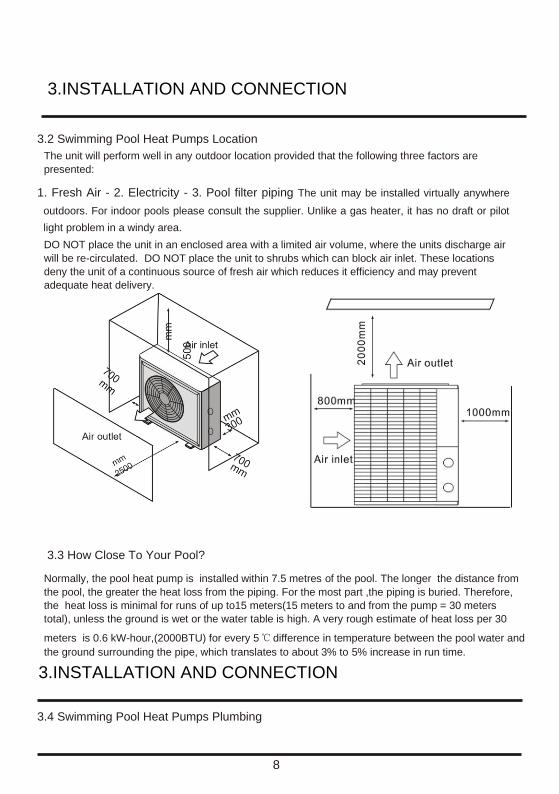
3.2 Swimming Pool Heat Pumps Location The unit will perform well in any outdoor location provided that the following three factors are
presented:
1. Fresh Air - 2. Electricity - 3. Pool filter piping The unit may be installed virtually anywhere
outdoors. For indoor pools please consult the supplier. Unlike a gas heater, it has no draft or pilot
light problem in a windy area. DO NOT place the unit in an enclosed area with a limited air volume, where the units discharge air
will be re-circulated. DO NOT place the unit to shrubs which can block air inlet. These locations
deny the unit of a continuous source of fresh air which reduces it efficiency and may prevent
adequate heat delivery.
3.3 How Close To Your Pool?
Normally, the pool heat pump is installed within 7.5 metres of the pool. The longer the distance from
the pool, the greater the heat loss from the piping. For the most part ,the piping is buried. Therefore,
the heat loss is minimal for runs of up to15 meters(15 meters to and from the pump = 30 meters
total), unless the ground is wet or the water table is high. A very rough estimate of heat loss per 30
meters is 0.6 kW-hour,(2000BTU) for every 5 difference in temperature between the pool water and
the ground surrounding the pipe, which translates to about 3% to 5% increase in run time.
3.INSTALLATION AND CONNECTION
3.4 Swimming Pool Heat Pumps Plumbing
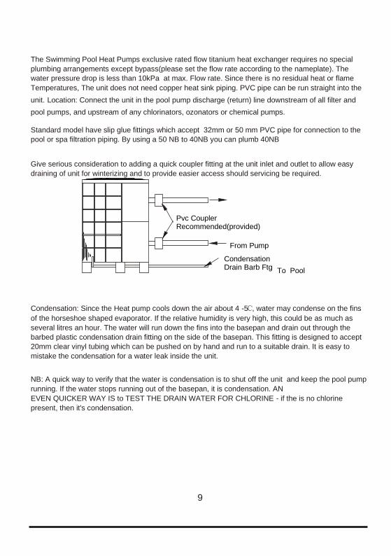
The Swimming Pool Heat Pumps exclusive rated flow titanium heat exchanger requires no special
plumbing arrangements except bypass(please set the flow rate according to the nameplate). The
water pressure drop is less than 10kPa at max. Flow rate. Since there is no residual heat or flame Temperatures, The unit does not need copper heat sink piping. PVC pipe can be run straight into the
unit. Location: Connect the unit in the pool pump discharge (return) line downstream of all filter and
pool pumps, and upstream of any chlorinators, ozonators or chemical pumps.
Standard model have slip glue fittings which accept 32mm or 50 mm PVC pipe for connection to the
pool or spa filtration piping. By using a 50 NB to 40NB you can plumb 40NB
Give serious consideration to adding a quick coupler fitting at the unit inlet and outlet to allow easy
draining of unit for winterizing and to provide easier access should servicing be required.
Condensation: Since the Heat pump cools down the air about 4 -5 , water may condense on the fins
of the horseshoe shaped evaporator. If the relative humidity is very high, this could be as much as
several litres an hour. The water will run down the fins into the basepan and drain out through the
barbed plastic condensation drain fitting on the side of the basepan. This fitting is designed to accept
20mm clear vinyl tubing which can be pushed on by hand and run to a suitable drain. It is easy to
mistake the condensation for a water leak inside the unit.
NB: A quick way to verify that the water is condensation is to shut off the unit and keep the pool pump
running. If the water stops running out of the basepan, it is condensation. AN EVEN QUICKER WAY IS to TEST THE DRAIN WATER FOR CHLORINE - if the is no chlorine
present, then it's condensation.
9
To Pool
From Pump
Pvc Coupler Recommended(provided)
Condensation Drain Barb Ftg
10
3.INSTALLATION AND CONNECTION
3.5 Swimming Pool Heat Pumps Electrical Wiring NOTE: Although the unit heat exchanger is electrically isolated from the rest of the unit, it simply
prevents the flow of electricity to or from the pool water. Grounding the unit is still required to protect
you against short circuits inside the unit. Bonding is also required. The unit has a separate molded-in junction box with a standard electrical conduit nipple already in
place. Just remove the screws and the front panel, feed your supply lines in through the conduit nipple
and wire-nut the electric supply wires to the three connections already in the junction box (four
connections if three phase). To complete electrical hookup, connect Heat Pump by electrical conduit,
UF cable or other suitable means as specified (as permitted by local electrical authorities) to a
dedicated AC power supply branch circuit equipped with the proper circuit breaker, disconnect or time
delay fuse protection.
Disconnect - A disconnect means (circuit breaker , fused or un-fused switch) should be located within
sight of and readily accessible from the unit, This is common practice on commercial and residential
air conditioners and heat pumps. It prevents remotely-energizing unattended equipment and permits
turning off power at the unit while the unit is being serviced.
3.6 Initial startup of the Unit NOTE- In order for the unit to heat the pool or spa, the filter pump must
be running to circulate water through the heat exchanger.
Start up Procedure - After installation is completed, you should follow these steps: 1. Turn on your filter pump. Check for water leaks and verify flow to and from the pool. 2. Turn
on the electrical power supply to the unit, then press the key ON/OFF of wire controller, It should
start in several seconds. 3. After running a few minutes make sure the air leaving the top(side) of the unit
iscooler(Between 5-10 ) 4. With the unit operating turn the filter pump off. The unit should also turn off automatically,5.
Allow the unit and pool pump to run 24 hours per day until desired pool water temperature is reached.
When the water-in temperature reaches this setting, the unit will slow down for a period of time, if the
temperature is maintained for 45 minutes the unit will turn off. The unit will now automatically restart
(as long as your pool pump is running)when the pool temperature drops more than 0.2 below set
temperature.
Time Delay- The unit is equipped with a 3 minute built-in solid state restart delay included to protect
control circuit components and to eliminate restart cycling and contactor chatter. This time delay will
automatically restart the unit approximately 3 minutes after each control circuit interruption. Even a
brief power interruption will activate the solid state 3 minute restart delay and prevent the unit from
starting until the 5 minute countdown is completed. Power interruptions during the delay period will
have no effect on the 3 minute countdown.

4.Use and Operation Instruction
11
4.1.Interface display
4.2.Key and icon function instruction
4.2.1 Key function instruction
Key symbols Designation
Function
Mute key
Under the heating mode or heating mode under the automatic mode, the mute key operation is effective and used to enter and exit the mute mode with one click.
Mode key It is used to switch the unit mode, temperature setting, and parameter setting.
On-off key It is used to carry out startup & shutdown, cancel current operation,and return to the last level of operation.
Up key It is used to page up, and increase variable value.
Down key It is used to page down, and decrease variable value.
Clock key It is used as user clock, and to carry out timing setting.
12
4.Use and Operation Instruction
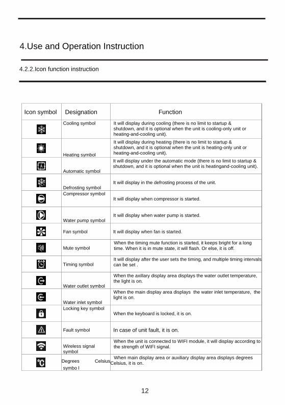
4.2.2.Icon function instruction
Icon symbol Designation Function
Cooling symbol It will display during cooling (there is no limit to startup & shutdown, and it is optional when the unit is cooling-only unit or heating-and-cooling unit).
Heating symbol
It will display during heating (there is no limit to startup & shutdown, and it is optional when the unit is heating-only unit or heating-and-cooling unit).
Automatic symbol
It will display under the automatic mode (there is no limit to startup & shutdown, and it is optional when the unit is heatingand-cooling unit).
Defrosting symbol It will display in the defrosting process of the unit.
Compressor symbol
It will display when compressor is started.
Water pump symbol It will display when water pump is started.
Fan symbol It will display when fan is started.
Mute symbol When the timing mute function is started, it keeps bright for a long time. When it is in mute state, it will flash. Or else, it is off.
Timing symbol It will display after the user sets the timing, and multiple timing intervals can be set .
Water outlet symbol
When the axillary display area displays the water outlet temperature, the light is on.
Water inlet symbol
When the main display area displays the water inlet temperature, the light is on.
Locking key symbol
When the keyboard is locked, it is on.
Fault symbol In case of unit fault, it is on.
Wireless signal symbol
When the unit is connected to WIFI module, it will display according to the strength of WIFI signal.
Degrees Celsius symbo l
When main display area or auxiliary display area displays degrees
Celsius, it is on.
4.Use and Operation Instruction
13
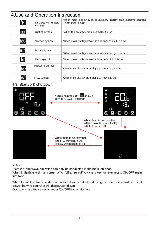
Degrees Fahrenheit symbol
When main display area or auxiliary display area displays degrees Fahrenheit, it is on.
Setting symbol When the parameter is adjustable, it is on
Second symbol When main display area displays second digit, it is on.
Minute symbol When main display area displays minute digit, it is on.
Hour symbol When main display area displays hour digit, it is on.
Pressure symbol
When main display area displays pressure, it is on.
Flow symbol When main display area displays flow, it is on.
4.3. Startup & shutdown
Notes: Startup & shutdown operation can only be conducted in the main interface. When it displays with half screen off or full screen off, click any key for returning to ON/OFF main
interface.
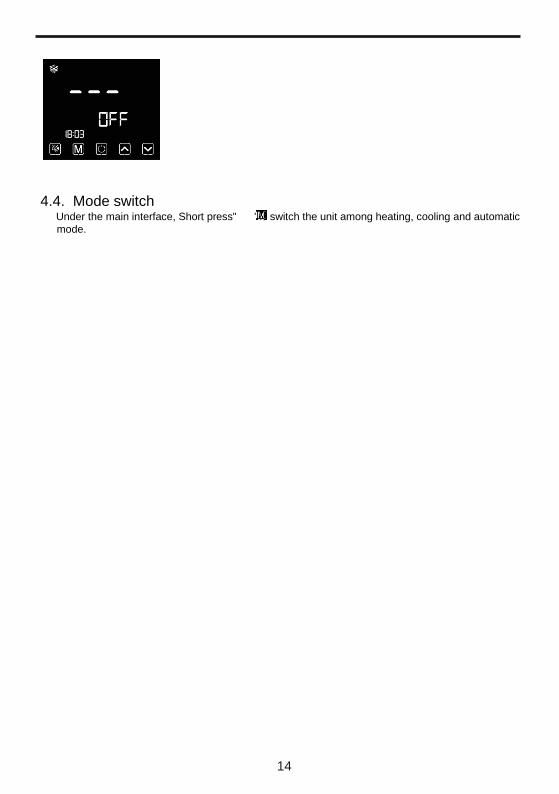
When the unit is started under the control of wire controller, if using the emergency switch to shut
down, the wire controller will display as follows: Operations are the same as under ON/OFF main interface.
Keep long press of " "for 0.5 s to enter ON/OFF interface
When there is no operation within 15 minutes, it will display with full screen off
When there is no operation within 1 minute, it will display with half screen off
14
4.4. Mode switch Under the main interface, Short press" "to switch the unit among heating, cooling and automatic
mode.
4.Use and Operation Instruction
15
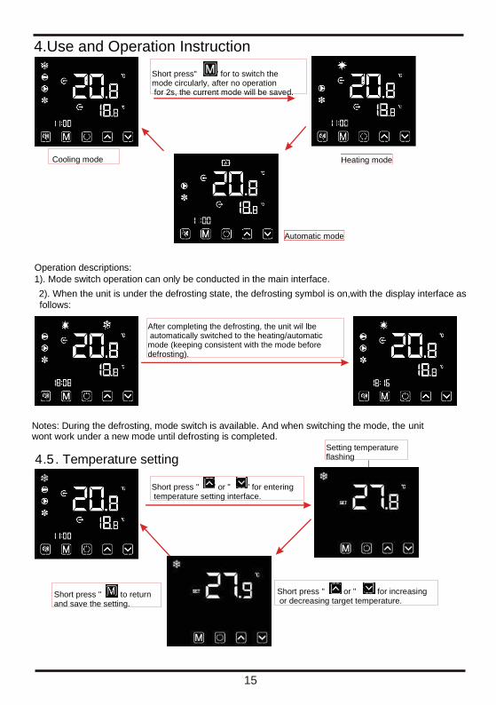
Operation descriptions: 1). Mode switch operation can only be conducted in the main interface. 2). When the unit is under the defrosting state, the defrosting symbol is on,with the display interface as
follows:
Short press" " for to switch the mode circularly, after no operation for 2s, the current mode will be saved.
Cooling mode
Automatic mode
Heating mode
After completing the defrosting, the unit wil lbe automatically switched to the heating/automatic mode (keeping consistent with the mode before defrosting).
Notes: During the defrosting, mode switch is available. And when switching the mode, the unit wont work under a new mode until defrosting is completed.
4 . Temperature setting .5
Short press " " or " " for increasing or decreasing target temperature.
Short press " " to return and save the setting.
Setting temperature flashing
Short press " " or " " for entering temperature setting interface.
4.Use and Operation Instruction
16
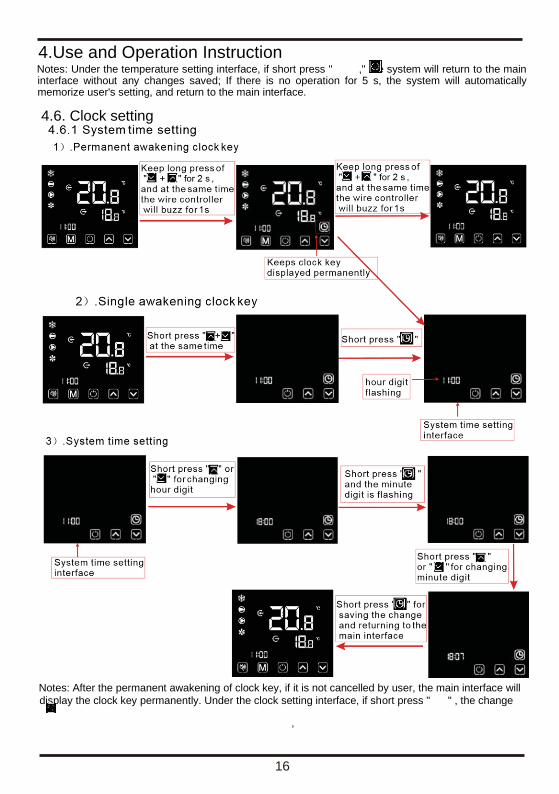
Notes: Under the temperature setting interface, if short press " ," the system will return to the main interface without any changes saved; If there is no operation for 5 s, the system will automatically memorize user's setting, and return to the main interface.
4.6. Clock setting
Notes: After the permanent awakening of clock key, if it is not cancelled by user, the main interface will
display the clock key permanently. Under the clock setting interface, if short press " " , the change
4.Use and Operation Instruction
17
will not be saved and return to the main interface; if there is no operation for 20s, the system will
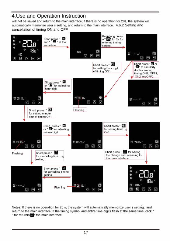
automatically memorize user s setting, and return to the main interface. 4.6.2 Setting and
cancellation of timing ON and OFF
Notes: If there is no operation for 20 s, the system will automatically memorize user s setting, and
return to the main interface; If the timing symbol and entire time digits flash at the same time, click "
" for returning to the main interface.
18
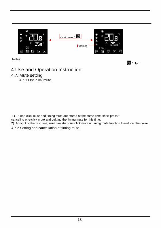
4.Use and Operation Instruction 4.7. Mute setting
4.7.1 One-click mute
1) . If one-click mute and timing mute are stared at the same time, short press " canceling one-click mute and quitting the timing mute for this time. 2). At night or the rest time, user can start one-click mute or timing mute function to reduce the noise. 4.7.2 Setting and cancellation of timing mute
short press " "
Notes: " for
Flashing

19
Notes:
4.Use and Operation Instruction 1). When the mute icon" " is lighten:The timing mute has been set, but it's not under mute status. 2). When the mute icon" " flash:It's under the mute status. 3). When the mute icon" "disappear: The timing mute is not set.
4.8.Keyboard lock To avoid others' misoperation, please lock the wire controller after completing the
setting.
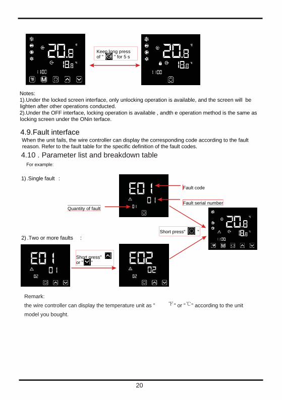
20
Notes: 1).Under the locked screen interface, only unlocking operation is available, and the screen will be
lighten after other operations conducted. 2).Under the OFF interface, locking operation is available , andth e operation method is the same as
locking screen under the ONin terface.
4.9.Fault interface When the unit fails, the wire controller can display the corresponding code according to the fault
reason. Refer to the fault table for the specific definition of the fault codes.
4.10 . Parameter list and breakdown table
Keep long press of " " for 5 s
2) .Two or more faults :
.Single fault : 1)
Short press" " or " "
Fault code
Fault serial
number Quantity
of fault
Short press" "
For example:
Remark: the wire controller can display the temperature unit as " " or " " according to the unit model you bought.
21
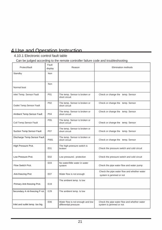
4.Use and Operation Instruction 4.10.1 Electronic control fault table Can be judged according to the remote controller failure code and troubleshooting
Protect/fault Fault
display Reason Elimination methods
Standby Non
Normal boot Non
Inlet Temp. Sensor Fault P01 The temp. Sensor is broken or short circuit
Check or change the temp. Sensor
Outlet Temp.Sensor Fault P02 The temp. Sensor is broken or
short circuit Check or change the temp. Sensor
Amibent Temp.Sensor Fault P04 The temp. Sensor is broken or short circuit
Check or change the temp. Sensor
Coil Temp.Sensor Fault P05 The temp. Sensor is broken or
short circuit Check or change the temp. Sensor
Suction Temp.Sensor Fault P07 The temp. Sensor is broken or short circuit Check or change the temp. Sensor
Discharge Temp.Sensor Fault P081
The temp. Sensor is broken or short circuit Check or change the temp. Sensor
High Pressure Prot. E01
The high-preesure switch is broken Check the pressure switch and cold circuit
Low Pressure Prot. E02 Low pressure1 protection Check the pressure switch and cold circuit
Flow Switch Prot. E03 No water/little water in water
system Check the pipe water flow and water pump
Anti-freezing Prot E07 Water flow is not enough Check the pipe water flow and whether water system is jammed or not
Primary Anti-freezing Prot. E19 The ambient temp. Is low
Secondary A nti-freezing P rot. E29 The ambient temp. Is low
Inlet and outlet temp. too big E06 Water flow is not enough and low
differential pressure Check the pipe water flow and whether water system is jammed or not
22
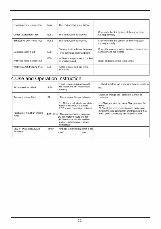
Low temperature protection Non The environment temp. is low
Comp. Overcurrent Prot. E051 The compressor is overload Check whether the system of the compressor running normally
Exhaust Air over Temp Prot. P082 The compressor is overload Check whether the system of the compressor running normally
Communication Fault E08 Communicat ion failure between wire controller and mainboard
Check the wire connection between remote wire controller and main board
Antifreeze Temp. Sensor Fault P09 antifreeze temp sensor is broken
or short circuited check and replace this temp sensor
Waterway Anti-freezing Prot. E05 water temp.or ambient temp. is too low
4.Use and Operation Instruction
EC fan feedback Fault F051 There is something wrong with fan motor and fan motor stops running
Check whether fan motor is broken or locked or not
Pressure sensor Fault PP The pressure Sensor is broken Check or change the pressure Sensor or pressure
Fan Motor1 FaultFan Motor1 Fault F031F031
11. Motor is in locked-rotor state. Motor is in locked-rotor state 22.The wire connection between
.The wire connection between DC-fan motor module and fan DC-fan motor module and fan motor is in badmotor is in bad contacttact
1.1.Change a new fan motorChange a new fan motor 22.Check the wire connection and make sure .Check the wire connection and make sure they are in good contactthey are in g od contact
Low AT ProtectionLow AT Protection
TPTP Ambient tempAmbient temp is too low t low
23
4.Use and Operation Instruction
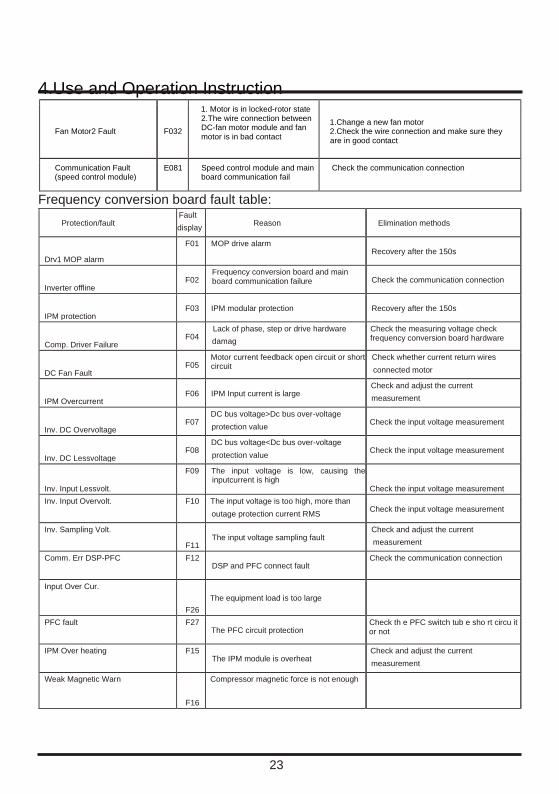
Fan Motor2 Fault F032
1. Motor is in locked-rotor state 2.The wire connection between DC-fan motor module and fan motor is in bad contact
1.Change a new fan motor 2.Check the wire connection and make sure they are in good contact
Communication Fault (speed control module)
E081 Speed control module and main board communication fail
Check the communication connection
Frequency conversion board fault table:
Protection/fault Fault display Reason Elimination methods
Drv1 MOP alarm F01 MOP drive alarm
Recovery after the 150s
Inverter offline F02
Frequency conversion board and main board communication failure Check the communication connection
IPM protection F03 IPM modular protection Recovery after the 150s
Comp. Driver Failure F04
Lack of phase, step or drive hardware damag
Check the measuring voltage check frequency conversion board hardware
DC Fan Fault F05
Motor current feedback open circuit or short circuit
Check whether current return wires connected motor
IPM Overcurrent F06 IPM Input current is large
Check and adjust the current measurement
Inv. DC Overvoltage F07
DC bus voltage>Dc bus over-voltage protection value Check the input voltage measurement
Inv. DC Lessvoltage F08
DC bus voltage<Dc bus over-voltage protection value Check the input voltage measurement
Inv. Input Lessvolt. F09 The input voltage is low, causing the
inputcurrent is high Check the input voltage measurement
Inv. Input Overvolt. F10 The input voltage is too high, more than outage protection current RMS Check the input voltage measurement
Inv. Sampling Volt. F11
The input voltage sampling fault Check and adjust the current measurement
Comm. Err DSP-PFC F12 DSP and PFC connect fault
Check the communication connection
Input Over Cur.
F26 The equipment load is too large
PFC fault F27 The PFC circuit protection
Check th e PFC switch tub e sho rt circu it or not
IPM Over heating F15 The IPM module is overheat
Check and adjust the current measurement
Weak Magnetic Warn
F16
Compressor magnetic force is not enough
24
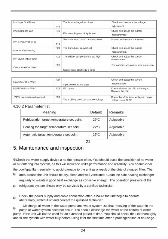
Inv. Input Out Phase F17
The input voltage lost phase Check and measure the voltage adjustment
IPM Sampling Cur. F18 IPM sampling electricity is fault
Check and adjust the current measurement
Inv. Temp. Probe Fail F19
Sensor is short circuit or open circuit Inspect and replace the sensor
Inverter Overheating F20 The transducer is overheat Check and adjust the current
measurement
Inv. Overheating Warn F22 Transducer temperature is too high Check and adjust the current
measurement
Comp. OverCur. Warn F23
Compressor electricity is large The compressor over-current protection
Input Over Cur. Warn F24
Input current is too large Check and adjust the current measurement
EEPROM Error Warn F25 MCU error Check whether the chip is damaged Replace the chip
V15V over/undervoltage fault F28 The V15V is overload or undervoltage
Check the V15V input voltage in range 13.5v~16.5v or not
4.10.2 Parameter list
Meaning Default Remarks
Refrigeration target temperature set point 27ºC Adjustable
Heating the target temperature set point 27ºC Adjustable
Automatic target temperature set point 27ºC Adjustable
21
5. Maintenance and inspection
Check the water supply device a nd the release often. You should avoid the condition of no water or air entering into system, as this will influence unit's performance and reliability. You should clear
the pool/spa filter regularly to avoid damage to the unit as a result of the dirty of clogged filter. The
area around the unit should be dry, clean and well ventilated. Clean the side heating exchanger
regularly to maintain good heat exchange as conserve energy . The operation pressure of the
refrigerant system should only be serviced by a certified technician . Check the power supply and cable connection often,.Should the unit begin to operate
abnormally, switch it off and contact the qualified technician.
Discharge all water in the water pump and water system ,so that freezing of the water in the
pump or water system does not occur. You should discharge the water at the bottom of water
pump if the unit will not be used for an extended period of time. You should check the unit thoroughly
and fill the system with water fully before using it for the first time after a prolonged time of no usage.

25
Checks to the area Prior to beginning work on systems containing flammable refrigerants, safety checks are necessary
to ensure that the risk of ignition is minimised. For repair to the refrigerating system, the following
precautions shall be complied with prior to conducting work on the system prolonged period of no
usage.
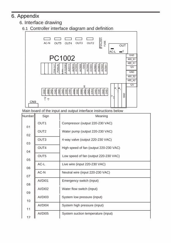
6. Appendix
6. Interface drawing 6.1 Controller interface diagram and definition
Main board of the input and output interface instructions below Number Sign Meaning
OUT1 Compressor (output 220-230 VAC)
OUT2 Water pump (output 220-230 VAC)
OUT3 4-way valve (output 220-230 VAC)
OUT4 High speed of fan (output 220-230 VAC)
OUT5 Low speed of fan (output 220-230 VAC)
AC-L Live wire (input 220-230 VAC)
AC-N Neutral wire (input 220-230 VAC)
AI/DI01 Emergency switch (input)
AI/DI02 Water flow switch (input)
AI/DI03 System low pressure (input)
AI/DI04 System high pressure (input)
AI/DI05 System suction temperature (input)
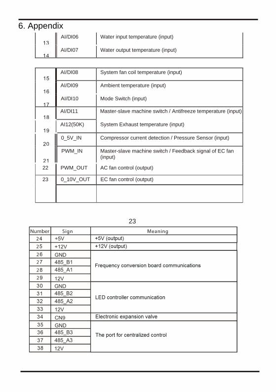
6. Appendix
AI/DI06 Water input temperature (input)
AI/DI07 Water output temperature (input)
AI/DI08 System fan coil temperature (input)
AI/DI09 Ambient temperature (input)
AI/DI10 Mode Switch (input)
AI/DI11 Master-slave machine switch / Antifreeze temperature (input)
AI12(50K) System Exhaust temperature (input)
0_5V_IN Compressor current detection / Pressure Sensor (input)
PWM_IN Master-slave machine switch / Feedback signal of EC fan (input)
22 PWM_OUT AC fan control (output)
23
0_10V_OUT EC fan control (output)
23

6. Appendix
Notes: When the unit uses EC fan, PWM-IN port is used for feedback input of EC fan by default, and
AI/DI11 port is used as master-slave switch by default; when the unit uses non-EC fan, PWM-IN
port is used as master-slave switch by default, and AI/DI11 port is used as anti-freezing protection
switch by default.
24

6. Appendix
6. Appendix
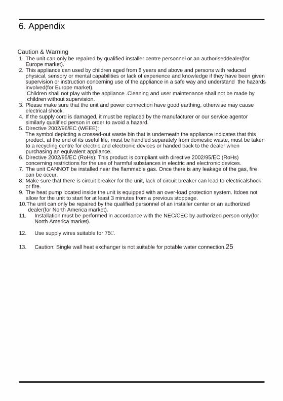
Caution & Warning 1. The unit can only be repaired by qualified installer centre personnel or an authoriseddealer(for
Europe market). 2. This appliance can used by children aged from 8 years and above and persons with reduced
physical, sensory or mental capabilities or lack of experience and knowledge if they have been given supervision or instruction concerning use of the appliance in a safe way and understand the hazards involved(for Europe market). Children shall not play with the appliance .Cleaning and user maintenance shall not be made by children without supervision.
3. Please make sure that the unit and power connection have good earthing, otherwise may cause electrical shock.
4. If the supply cord is damaged, it must be replaced by the manufacturer or our service agentor similarly qualified person in order to avoid a hazard.
5. Directive 2002/96/EC (WEEE): The symbol depicting a crossed-out waste bin that is underneath the appliance indicates that this product, at the end of its useful life, must be handled separately from domestic waste, must be taken to a recycling centre for electric and electronic devices or handed back to the dealer when purchasing an equivalent appliance.
6. Directive 2002/95/EC (RoHs): This product is compliant with directive 2002/95/EC (RoHs) concerning restrictions for the use of harmful substances in electric and electronic devices.
7. The unit CANNOT be installed near the flammable gas. Once there is any leakage of the gas, fire can be occur.
8. Make sure that there is circuit breaker for the unit, lack of circuit breaker can lead to electricalshock or fire.
9. The heat pump located inside the unit is equipped with an over-load protection system. Itdoes not allow for the unit to start for at least 3 minutes from a previous stoppage.
10.The unit can only be repaired by the qualified personnel of an installer center or an authorized dealer(for North America market).
11. Installation must be performed in accordance with the NEC/CEC by authorized person only(for North America market).
12. Use supply wires suitable for 75 .
13. Caution: Single wall heat exchanger is not suitable for potable water connection.25
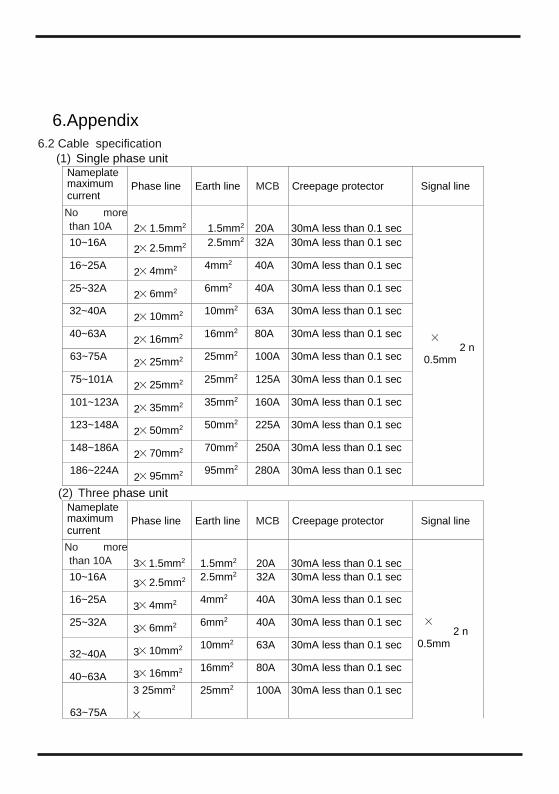
6.Appendix
6.2 Cable specification (1) Single phase unit
Nameplate maximum current
Phase line Earth line MCB Creepage protector Signal line
No more than 10A 2 1.5mm2 1.5mm2 20A 30mA less than 0.1 sec
2 n 0.5mm
10~16A 2 2.5mm2 2.5mm2 32A 30mA less than 0.1 sec
16~25A 2 4mm2 4mm2 40A 30mA less than 0.1 sec
25~32A 2 6mm2 6mm2 40A 30mA less than 0.1 sec
32~40A 2 10mm2 10mm2 63A 30mA less than 0.1 sec
40~63A 2 16mm2 16mm2 80A 30mA less than 0.1 sec
63~75A 2 25mm2 25mm2 100A 30mA less than 0.1 sec
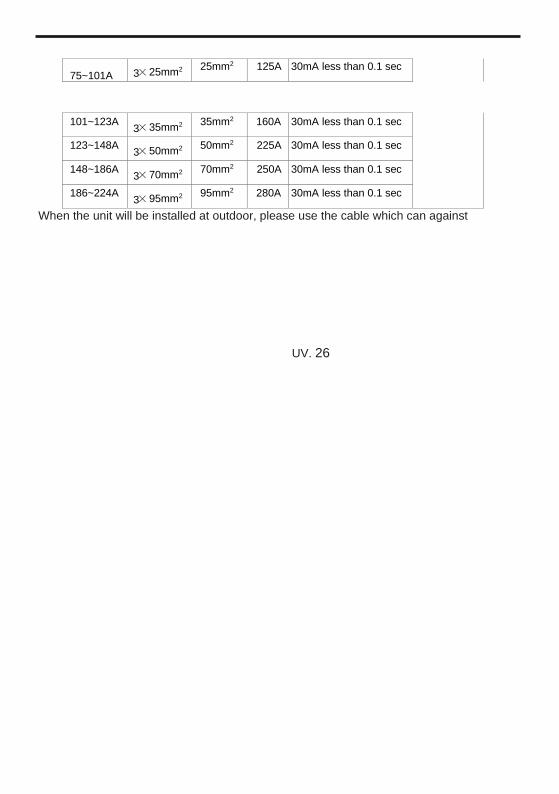
75~101A 2 25mm2 25mm2 125A 30mA less than 0.1 sec
101~123A 2 35mm2 35mm2 160A 30mA less than 0.1 sec
123~148A 2 50mm2 50mm2 225A 30mA less than 0.1 sec
148~186A 2 70mm2 70mm2 250A 30mA less than 0.1 sec
186~224A 2 95mm2 95mm2 280A 30mA less than 0.1 sec
(2) Three phase unit Nameplate maximum current
Phase line Earth line MCB Creepage protector Signal line
No more than 10A 3 1.5mm2 1.5mm2 20A 30mA less than 0.1 sec
2 n 0.5mm
10~16A 3 2.5mm2 2.5mm2 32A 30mA less than 0.1 sec
16~25A 3 4mm2 4mm2 40A 30mA less than 0.1 sec
25~32A 3 6mm2 6mm2 40A 30mA less than 0.1 sec
32~40A 3 10mm2 10mm2 63A 30mA less than 0.1 sec
40~63A 3 16mm2 16mm2 80A 30mA less than 0.1 sec
63~75A
3 25mm2
25mm2 100A 30mA less than 0.1 sec
75~101A 3 25mm2 25mm2 125A 30mA less than 0.1 sec
101~123A 3 35mm2 35mm2 160A 30mA less than 0.1 sec
123~148A 3 50mm2 50mm2 225A 30mA less than 0.1 sec
148~186A 3 70mm2 70mm2 250A 30mA less than 0.1 sec
186~224A 3 95mm2 95mm2 280A 30mA less than 0.1 sec
When the unit will be installed at outdoor, please use the cable which can against
UV. 26


Thanks for choosing our product.
Please, read carefully this manual
before using the product.
WIFI LION
WIFILION
OWNER’S MANUAL
WIFI MODULE FOR
SWIMMING POOL HEAT PUMP
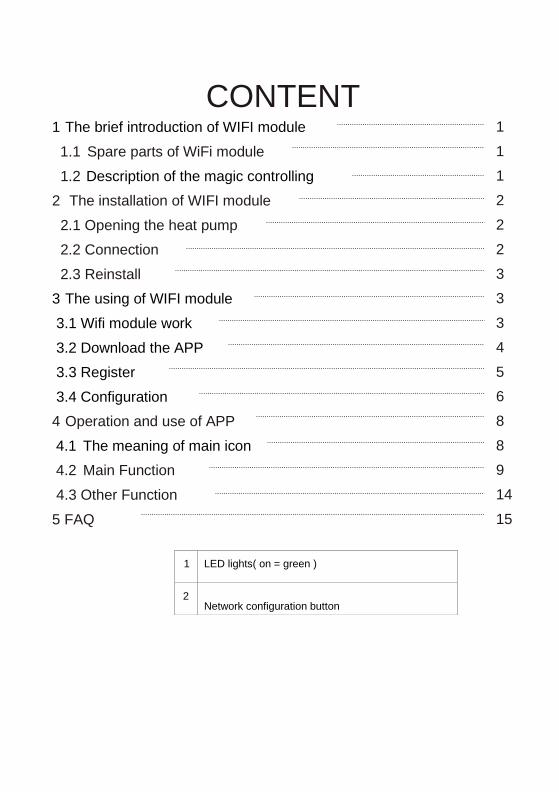
CONTENT
1 LED lights( on = green )
2 Network configuration button
1 The brief introduction of WIFI module
Description of the magic controlling
The using of WIFI module 3
3.1 Wifi module work
3.2 Download the APP
3.3 Register
3.4 Configuration
The meaning of main icon 4.1
1.1 Spare parts of WiFi module
1.2
2 The installation of WIFI module
2.1 Opening the heat pump
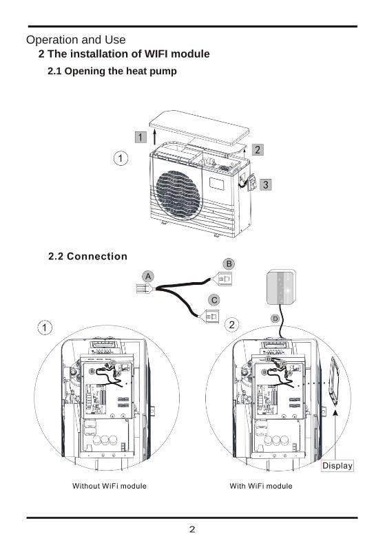
2.2 Connection
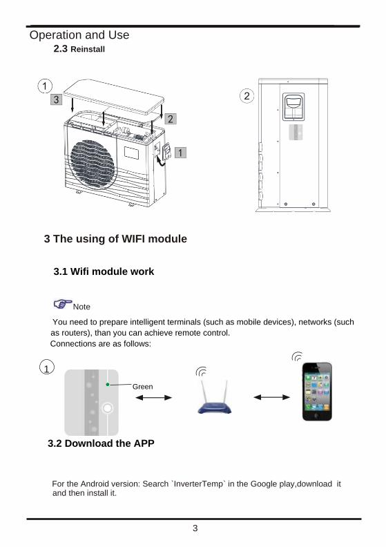
2.3 Reinstall
Operation and use of APP 4
4.2 Main Function
4.3 Other Function
5 FAQ
1
1
1
2
2
2
3
3
3
4
5
6
8
8
9
14
15
Operation and Use
1
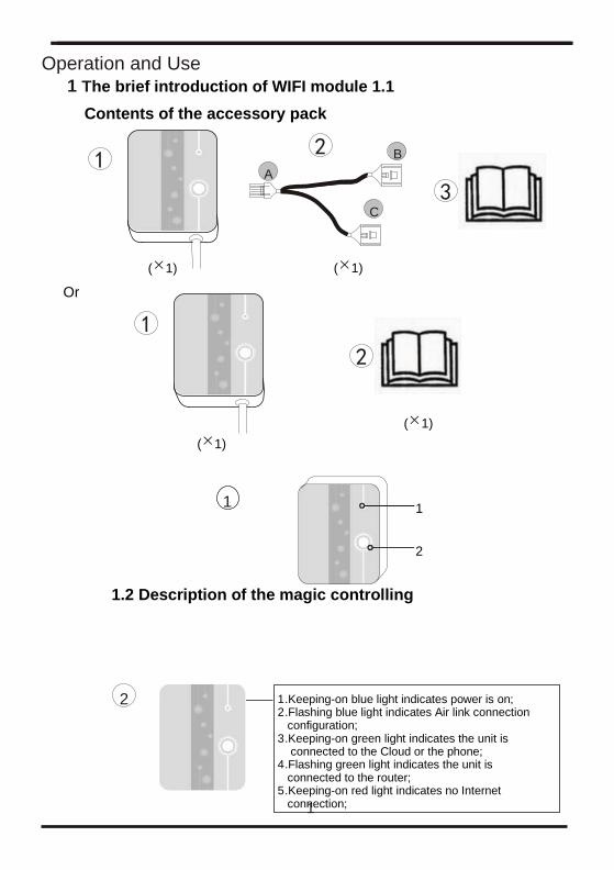
1 The brief introduction of WIFI module 1.1
Contents of the accessory pack
1.2 Description of the magic controlling
( 1) 1) (
1) (
1) (
Or
A B
C
1 .Keeping-on blue light indicates power is on; 2 .Flashing blue light indicates Air link connection configuration; 3 .Keeping-on green light indicates the unit is connected to the Cloud or the phone; 4 .Flashing green light indicates the unit is connected to the router; 5 .Keeping-on red light indicates no Internet connection;
2
1 1
2
Operation and Use
2 The installation of WIFI module
2.1 Opening the heat pump
Operation and Use
3
2.3 Reinstall
3 The using of WIFI module
3.1 Wifi module work
Note
You need to prepare intelligent terminals (such as mobile devices), networks (such
as routers), than you can achieve remote control. Connections are as follows:
3.2 Download the APP
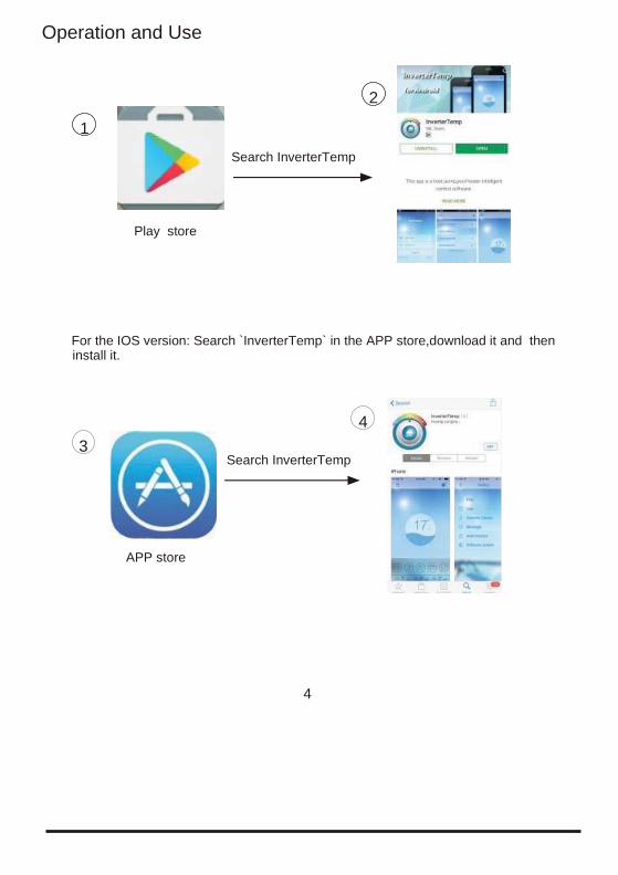
For the Android version: Search `InverterTemp` in the Google play,download it and then install it.
Green
1
Operation and Use
For the IOS version: Search `InverterTemp` in the APP store,download it and then install it.
4
Play store
Search InverterTemp
1
2
APP store
Search InverterTemp 3
4
Operation and Use
5
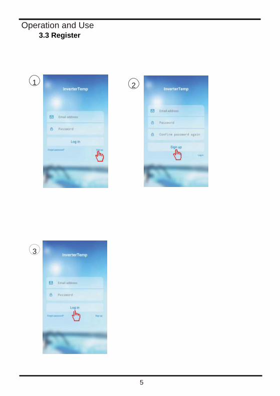
3.3 Register
1 2
3
Operation and Use
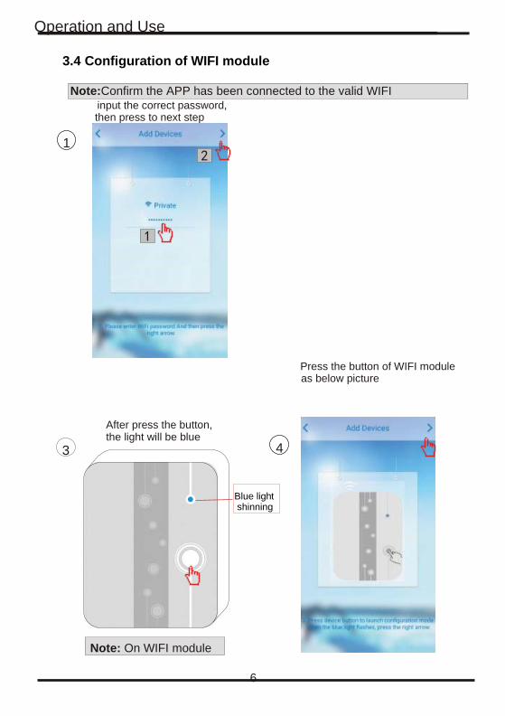
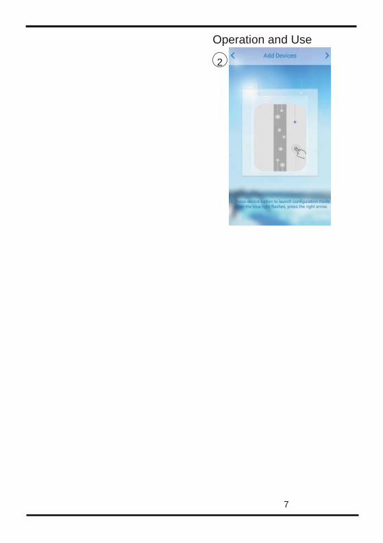
3.4 Configuration of WIFI module
Note:Confirm the APP has been connected to the valid WIFI input the correct password, then press to next step
Press the button of WIFI module as below picture
1
6
After press the button, the light will be blue
3 4
Note: On WIFI module
Blue light shinning
Operation and Use
7
2
Operation and Use
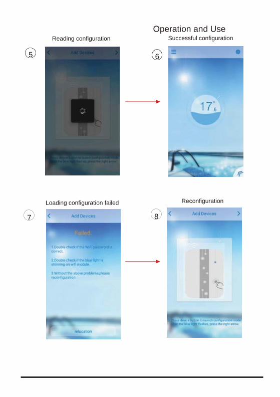
Reconfiguration Loading configuration failed
7 8
Reading configuration Successful configuration
5 6
9
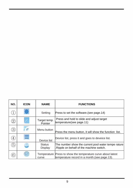
NO. ICON NAME FUNCTIONS
Setting Press to set the software.(see page.14)
Target temp.
Pointer
Press and hold to slide and adjust target temperature(see page.11)
Menu button Press the menu button, it will show the function list.
Device list
Device list, press it and goes to deveice list.
Status Display
The number show the current pool water tempe rature .Ripple on behalf of the machine switch.
Temperature curve
Press to show the temperature curve about latest temperature record in a month.(see page.13).
Operation and Use
10
Operation and Use
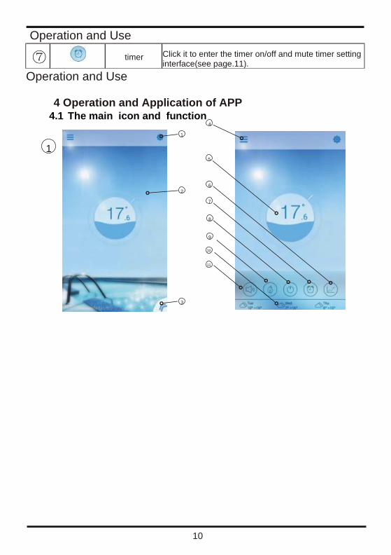
4 Operation and Application of APP
timer Click it to enter the timer on/off and mute timer setting interface(see page.11).
4.1 The main icon and function
1
9
8
3
4
5
6
7
1
10
11
2
Operation and Use
11
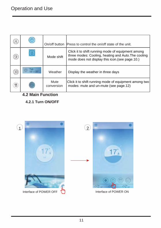
On/off button Press to control the on/off state of the unit.
Mode shift
Click it to shift running mode of equipment among three modes: Cooling, heating and Auto.The cooling mode does not display this icon.(see page.10.)
Weather Display the weather in three days
Mute conversion
Click it to shift running mode of equipment among two modes: mute and un-mute (see page.12)
4.2 Main Function
4.2.1 Turn ON/OFF
2 1
Interface of POWER OFF Interface of POWER ON

Operation and Use
12
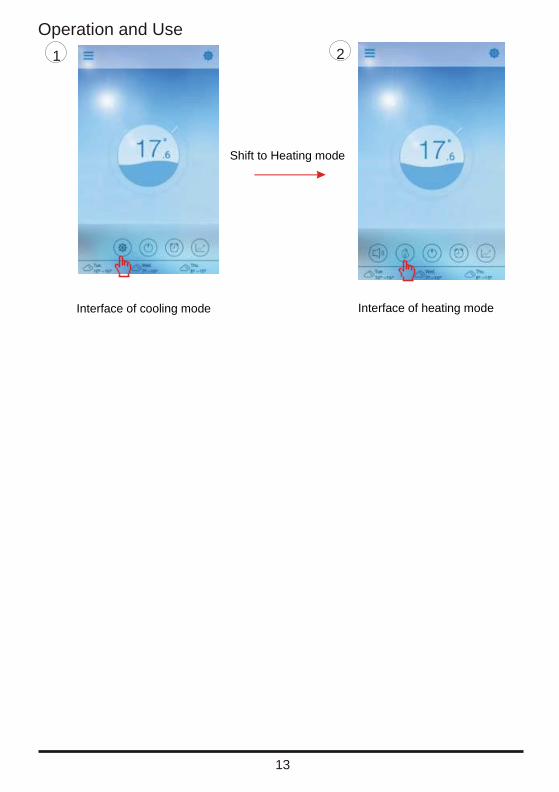
4.2.2 Mode s shifting
Cick theMode shifticon to shift running mode of equipment.
The sequence of shifting is Cooling Heating Auto and that cycle repeats.
Auto mode
3 Shift to Cooling mode Shift to Auto mode
Operation and Use
13
1 2
Shift to Heating mode
Interface of cooling mode Interface of heating mode
Operation and Use
14
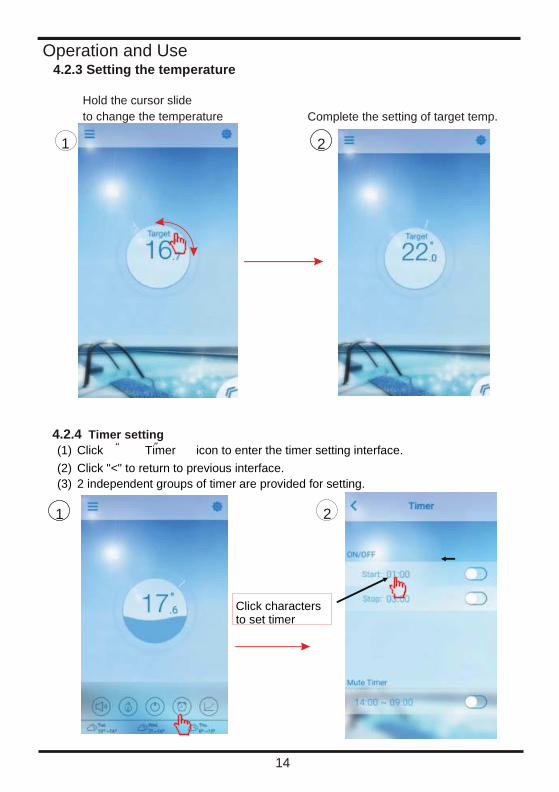
4.2.3 Setting the temperature
4.2.4 Timer setting
(1) Click Timer icon to enter the timer setting interface. (2) Click "<" to return to previous interface. (3) 2 independent groups of timer are provided for setting.
2 1
Complete the setting of target temp. Hold the cursor slide to change the temperature
1 2
Click characters to set timer
Operation and Use
15
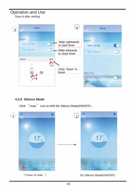
Save it after setting
3 4
Slide rightwards to start timer
Slide leftwards to close timer
Click "Save" to finish
1 2
On Silence Mode(ON/OFF)
Silence Mode 4.2.5
Power on state
Click mute icon to shift the Silence Mode(ON/OFF) .
Operation and Use
16
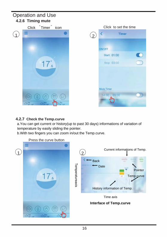
4.2.6 Timing mute
4.2.7 Check the Temp.curve
a.You can get current or history(up to past 30 days) informations of variation of
temperature by easily sliding the pointer. b.With two fingers you can zoom in/out the Temp.curve.
Press the curve button
Click to set the time Click Timer icon
1 2
1 2
Time axis
Interface of Temp.curve
History information of Temp.
Back
Pointer Date
Current informations of Temp.
Temp.curve

Operation and Use
17
4.3 Other Function
icon to enter the interface
of settings.
Back
Get answers of
problems you might
meet with
Set display Temp.unit
Rename your
equipment
Display error
information of
equipment
Authorise your After-
sale supplier to get
access to equipment
for 48 hours
FAQ ANSWER
Internet Acess successful: Green light
Click Settings
Operation and Use
18
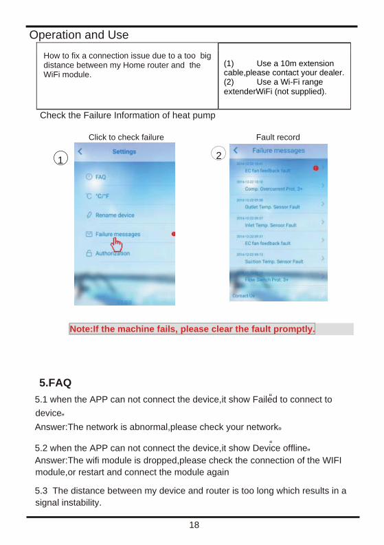
How to fix a connection issue due to a too big distance between my Home router and the WiFi module.
(1) Use a 10m extension cable,please contact your dealer. (2) Use a Wi-Fi range extenderWiFi (not supplied).
Check the Failure Information of heat pump
Click to check failure Fault record
Note:If the machine fails, please clear the fault promptly.
5.FAQ
5.1 when the APP can not connect the device,it show Failed to connect to
device
Answer:The network is abnormal,please check your network
5.2 when the APP can not connect the device,it show Device offline Answer:The wifi module is dropped,please check the connection of the WIFI
module,or restart and connect the module again
5.3 The distance between my device and router is too long which results in a
signal instability.
1 2
Operation and Use
19
Try to add another router between the original router and the equipment in order to relay Signal.
5.4 Something goes wrong with my equipment, what should I do? (1) Check error message in Setting(see page.20) or displayed in wire controller. (2) Look up corresponding error code in the instruction of your equipment to find out the
problem. (3) Contact your supplier for after-sales maintenance if necessary.