SMP und SCP dt / engl - pimmedia.schmalz.com · Bedienungsanleitung Ejektor SCP / SMP Operating...
16
Bedienungsanleitung Ejektor SCP / SMP Operating Instructions for Ejectors SCP / SMP 30.30.01.00248-DE-EN Status 06.2017 / Index 01 Seite / Page 1/16 J. Schmalz GmbH Johannes-Schmalz-Str. 1 D - 72293 Glatten Tel +49 +7443 / 2403 - 0 Fax +49 +7443 / 2403 - 259 http://www.schmalz.de e-mail: [email protected] Mitgeltende Dokumente / Applicable Documents Bedienungsanleitung / Operating instruction VS-V-PM 30.30.01.00047 Bedienungsanleitung / Operating instruction VS-V-A-EM 30.30.01.00036 Bedienungsanleitung / Operating instruction VS-V / VS-P / VS-P1 30.30.01.00033 Bedienungsanleitung / Operating instruction VS-Series 30.30.01.00031 Bedienungsanleitung / Operating instruction VS-D-Series 30.30.01.00011 Wartungsanleitung / Maintenance instruction SCP / SMP 30.30.01.00076 1. Technische Daten Funktionsprinzip: Vakuumerzeugung mittels gesteuerter Druckluft nach dem Venturiprinzip. Verwendung: Das Gerät dient zur Vakuumerzeugung das heißt zum Evakuieren von z. B. Sauggreifern zwecks Festhalten von Nutzlasten oder zum Evakuieren anderer Volumina. Als zu evakuierendes Medium sind Luft oder andere neutrale Gase gemäss EN 983 zugelassen. Das Gerät dient nicht zum Transport (Durchsaugen) von Flüssigkeiten und oder Granulaten. Medium: gefilterte (SCP 10/15: max. 20 μm, SCP 20-30 und SMP 15-30: max. 40 μm) und geölte oder nicht geölte Druckluft oder neutrale Gase gemäss EN 983. Ölempfehlung: Öl der Klasse H, (HM 32/HG 32) - ISO 3498 Viskositätenklasse: VG 32 - ISO 3448 zum Beispiel HYSPIN SP 32, MAGNAGLIDE D 32 (Castrol) zulässiger Betriebsdruck: 4 ... 6 bar (opt. Betriebsdruck am Ejektoreingang: 5 ... 6 bar ) Einbaulage Beliebig. Unter bestimmten Bedingungen (Staub; Öl o. a. Flüssigkeiten saugseitig) kann eine Einbaulage mit senkrecht nach unten gerichtetem Filter empfehlenswert sein. Versorgungsspannung (Schutzkleinspannung PELV) Magnetventile: +24 V DC -5% / +10% Vakuumschalter: +10.8 ... 30 V DC Zul. Temperaturbereich Umgebung: 0°C ... +45°C zu evakuierendes Medium: 0°C ... +60°C 1. Technical Data Principle of operation: vacuum generation by means of controlled compressed air (Venturi principle). Application: the unit is intended for vacuum generation, i.e. for evacuation of suction pads in order to secure loads, or for evacuation of other containers. It may be used for removal of air or other neutral gases in accordance with EN 983. The unit is not intended for the transport (pumping) of liquids or granulates. Medium: filtered (SCP 10/15: max. 20 μm, SCP 20-30 and SMP 15-30: max. 40 μm), oily or oil-free compressed air or neutral gases in accordance with EN 983. Recommended oil: oil of class H, (HM 32/HG 32) - ISO 3498 Viscosity class: VG 32 - ISO 3448, such as HYSPIN SP 32, MAGNAGLIDE D 32 (Castrol) Permissible operating pressure: 4.....6 bar (optimum pressure at ejector inlet: 5 ... 6 bar ) Installation orientation Any. Under certain conditions (dust; oil or similar liquids on the inlet side) it may be advisable to install with the filter pointing vertically downwards. Supply voltage (Protected extra-low voltage PELV) Solenoid valves: +24 V DC -5% / +10% Vacuum switches: +10.8 ... 30 V DC Permissible temperature range Ambient temperature: 0°C ... +45°C Medium to be evacuated: 0°C ... +60°C Verwendete Werkstoffe Materials Grundkörper Aluminiumlegierung eloxiert Body Aluminium alloy, anodised Filtergehäuse PC Filter casing PC Filtereinsatz Poroplast (PE-porös); Porenweite 50 μm Filter insert Poroplast (porous PE); pore size 50 μm Schalldämpfer Poroplast (PE-porös) Silencer Poroplast (porous PE) Deckel Schalldämpfer POM Silencer cover POM Schrauben Stahl schwarz chromatiert / verzinkt Screws Steel, black-chromated / galvanized Innenteile Messing; POM; Edelstahl; Al Internal parts Brass; POM; stainless steel; aluminium Dichtungen NBR Gaskets NBR Schmierung Silikonfrei Lubrication Silicone-free Magnetventile Gerät Spannung / Toleranz Leistung ED Schaltzeit E/A Handbetätigung Schutzbeschaltung Schaltzustand Schutzart SCP 10-15 24 V DC -5/+10% 1.3 W 100 % 8 ms / 10 ms tastend Z-Diode (im Ventil) LED - rot IP 40 (m. Stecker) SMP / SCP 20-30 24 V DC -5/+10% 2.5 W 100 % 10 ms / 12 ms tastend Varistor (im Stecker) LED - rot IP 65 (m. Stecker) Solenoid Valves Unit Voltage / Tolerance Power Duty cycle Switching time on/off Manual actuation Protective circuit Status indicator Enclosure type SCP 10-15 24 V DC -5/+10% 1.3 W 100 % 8 ms / 10 ms Push button Z diode (in valve) LED – red IP 40 (with plug) SMP / SCP 20-30 24 V DC -5/+10% 2.5 W 100 % 10 ms / 12 ms Push button Varistor (in plug) LED - red IP 65 (with plug) Typbezeichnungen Type Designations SCP Schmalz Compact Pump SCP Schmalz Compact Pump SMP Schmalz Mega Pump SMP Schmalz Mega Pump 10 ... 30 Düsendurchmesser=1.0 .... 3.0 mm 10 ... 30 Nozzle diameter = 1.0 ... 3.0 mm NO / NC Ruhestellung Saugventil (Magnetventil), NO = Stromlos offen , NC= stromlos geschlossen NO / NC Idle position of suction valve (solenoid valve), NO = normally open, NC = normally closed FS ohne Magnetventile, geeignet für Fremdsteuerung FS without solenoid valves, suitable for external control AS mit Abblasventil und Sicherheitsrückschlagventil AS with blow-off valve and non-return valve V ... mit Vakuumschalter V ... with vacuum switch R ... mit interner Regelung (Luftsparautomatik) R ... with internal regulation (automatic air-saving)
Transcript of SMP und SCP dt / engl - pimmedia.schmalz.com · Bedienungsanleitung Ejektor SCP / SMP Operating...
Bedienungsanleitung Ejektor SCP / SMP
Operating Instructions for Ejectors SCP / SMP 30.30.01.00248-DE-EN Status 06.2017 / Index 01 Seite / Page 1/16
J. Schmalz GmbH Johannes-Schmalz-Str. 1 D - 72293 Glatten Tel +49 +7443 / 2403 - 0 Fax +49 +7443 / 2403 - 259 http://www.schmalz.de e-mail: [email protected]
Mitgeltende Dokumente / Applicable Documents Bedienungsanleitung / Operating instruction VS-V-PM 30.30.01.00047
Bedienungsanleitung / Operating instruction VS-V-A-EM 30.30.01.00036
Bedienungsanleitung / Operating instruction VS-V / VS-P / VS-P1 30.30.01.00033
Bedienungsanleitung / Operating instruction VS-Series 30.30.01.00031
Bedienungsanleitung / Operating instruction VS-D-Series 30.30.01.00011
Wartungsanleitung / Maintenance instruction SCP / SMP 30.30.01.00076
1. Technische Daten Funktionsprinzip: Vakuumerzeugung mittels gesteuerter Druckluft nach dem Venturiprinzip.
Verwendung: Das Gerät dient zur Vakuumerzeugung das heißt zum Evakuieren von z. B. Sauggreifern zwecks Festhalten von Nutzlasten oder zum Evakuieren anderer Volumina. Als zu evakuierendes Medium sind Luft oder andere neutrale Gase gemäss EN 983 zugelassen.
Das Gerät dient nicht zum Transport (Durchsaugen) von Flüssigkeiten und oder Granulaten.
Medium: gefilterte (SCP 10/15: max. 20 µm, SCP 20-30 und
SMP 15-30: max. 40 µm) und geölte oder nicht geölte Druckluft oder neutrale Gase gemäss EN 983. Ölempfehlung: Öl der Klasse H, (HM 32/HG 32) - ISO 3498 Viskositätenklasse: VG 32 - ISO 3448 zum Beispiel HYSPIN SP 32, MAGNAGLIDE D 32 (Castrol)
zulässiger Betriebsdruck: 4 ... 6 bar (opt. Betriebsdruck am Ejektoreingang: 5 ... 6 bar )
Einbaulage
Beliebig. Unter bestimmten Bedingungen (Staub; Öl o. a. Flüssigkeiten saugseitig) kann eine Einbaulage mit senkrecht nach unten gerichtetem Filter empfehlenswert sein.
Versorgungsspannung
(Schutzkleinspannung PELV) Magnetventile: +24 V DC -5% / +10% Vakuumschalter: +10.8 ... 30 V DC
Zul. Temperaturbereich
Umgebung: 0°C ... +45°C zu evakuierendes Medium: 0°C ... +60°C
1. Technical Data Principle of operation: vacuum generation by means of controlled compressed air (Venturi principle).
Application: the unit is intended for vacuum generation, i.e. for evacuation of suction pads in order to secure loads, or for evacuation of other containers. It may be used for removal of air or other neutral gases in accordance with EN 983.
The unit is not intended for the transport (pumping) of liquids or granulates.
Medium: filtered (SCP 10/15: max. 20 µm, SCP 20-30 and
SMP 15-30: max. 40 µm), oily or oil-free compressed air or neutral gases in accordance with EN 983. Recommended oil: oil of class H, (HM 32/HG 32) - ISO 3498 Viscosity class: VG 32 - ISO 3448, such as HYSPIN SP 32, MAGNAGLIDE D 32 (Castrol)
Permissible operating pressure: 4.....6 bar (optimum pressure at ejector inlet: 5 ... 6 bar )
Installation orientation
Any. Under certain conditions (dust; oil or similar liquids on the inlet side) it may be advisable to install with the filter pointing vertically downwards.
Supply voltage
(Protected extra-low voltage PELV) Solenoid valves: +24 V DC -5% / +10% Vacuum switches: +10.8 ... 30 V DC
Permissible temperature range
Ambient temperature: 0°C ... +45°C Medium to be evacuated: 0°C ... +60°C
Verwendete Werkstoffe Materials
Grundkörper Aluminiumlegierung eloxiert Body Aluminium alloy, anodised
Filtergehäuse PC Filter casing PC
Filtereinsatz Poroplast (PE-porös); Porenweite 50 µm Filter insert Poroplast (porous PE); pore size 50 µm
Schalldämpfer Poroplast (PE-porös) Silencer Poroplast (porous PE)
Deckel Schalldämpfer POM Silencer cover POM
Schrauben Stahl schwarz chromatiert / verzinkt Screws Steel, black-chromated / galvanized
Innenteile Messing; POM; Edelstahl; Al Internal parts Brass; POM; stainless steel; aluminium
Dichtungen NBR Gaskets NBR
Schmierung Silikonfrei Lubrication Silicone-free
Magnetventile
Gerät Spannung / Toleranz Leistung ED Schaltzeit E/A Handbetätigung Schutzbeschaltung Schaltzustand Schutzart
SCP 10-15 24 V DC -5/+10% 1.3 W 100 % 8 ms / 10 ms tastend Z-Diode (im Ventil) LED - rot IP 40 (m. Stecker)
SMP / SCP 20-30 24 V DC -5/+10% 2.5 W 100 % 10 ms / 12 ms tastend Varistor (im Stecker) LED - rot IP 65 (m. Stecker)
Solenoid Valves
Unit Voltage / Tolerance Power Duty cycle Switching time on/off Manual actuation Protective circuit Status indicator Enclosure type
SCP 10-15 24 V DC -5/+10% 1.3 W 100 % 8 ms / 10 ms Push button Z diode (in valve) LED – red IP 40 (with plug)
SMP / SCP 20-30 24 V DC -5/+10% 2.5 W 100 % 10 ms / 12 ms Push button Varistor (in plug) LED - red IP 65 (with plug)
Typbezeichnungen Type Designations
SCP Schmalz Compact Pump SCP Schmalz Compact Pump
SMP Schmalz Mega Pump SMP Schmalz Mega Pump
10 ... 30 Düsendurchmesser=1.0 .... 3.0 mm 10 ... 30 Nozzle diameter = 1.0 ... 3.0 mm
NO / NC Ruhestellung Saugventil (Magnetventil), NO = Stromlos offen , NC= stromlos geschlossen
NO / NC Idle position of suction valve (solenoid valve), NO = normally open, NC = normally closed
FS ohne Magnetventile, geeignet für Fremdsteuerung FS without solenoid valves, suitable for external control
AS mit Abblasventil und Sicherheitsrückschlagventil AS with blow-off valve and non-return valve
V ... mit Vakuumschalter V ... with vacuum switch
R ... mit interner Regelung (Luftsparautomatik) R ... with internal regulation (automatic air-saving)
30.30.01.00248-DE-EN Status 06.2017 / Index 01 Seite / Page 2/16
Ejector SCP 10 - 15
(auch geregelte Version ...RD/RE / also regulated version ...RD/RE)
Ejectors SMP 15 - 30 and SCP 20 – 30
(auch geregelte Version ...RD/RE / also regulated version ...RD/RE)
Ejectors SCP 10 – 15 ...FS
(mit Fremdsteuerung / with external control)
Ejectors SMP 15 - 30 ... / SCP 20 – 30
(mit Fremdsteuerung / with external control)
Ejectors SCP 10 – 15 ...FS-RP (mit Fremdsteuerung, pneumatisch
geregelt / with external control, pneumatically regulated)
Ejectors SMP 15 - 30 ... / SCP 20 – 30 ... FS-RP (mit Fremdsteuerung,
pneumatisch geregelt / with external control, pneumatically regulated)
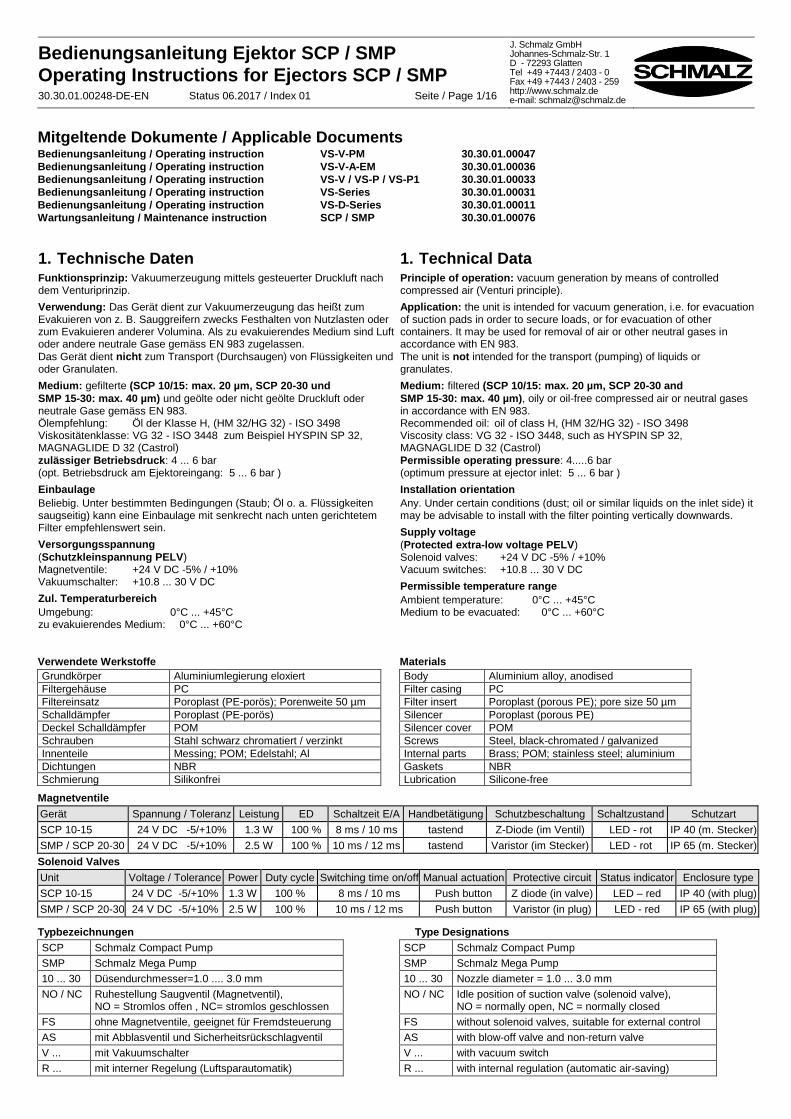
1 Befestigungsbohrungen des Ejektors SCP 10-15: Durchmesser 4,5 mm SMP / SCP 20-30: Durchmesser 5,5 mm
2 Vakuumanschluss SCP 10-15: Anschlussgewinde G1/8“ SMP / SCP 20-30: Anschlussgewinde G3/8“
3 Druckluftanschluss SCP 10-15: Anschlussgewinde G1/8“ SMP / SCP 20-30: Anschlussgewinde G1/4“
4 Filtergehäuse
5 Filterelement
6 Schalldämpfer
7 Vakuumschalter
8 Elektrischer Anschluss Vakuumschalter (außer ... VPM) Bei allen Geräten: M8 x 1
9 Elektrischer Anschluss Pilotventil „Saugen“ SCP 10-15: formschlüssig rastend; nicht genormt SMP / SCP 20-30: Steckanschluss nach DIN 43650 Form C
10 Handhilfsbetätigung (tastend) Pilotventil „Saugen“
11 Elektrischer Anschluss Pilotventil „Abblasen“
12 Handhilfsbetätigung (tastend) Pilotventil „Abblasen“
13 Drosselschraube Abwurfimpuls (nur bei SMP...)
14 Steuerluftanschluss „Saugen“ Anschlussgewinde M5
15 Steuerluftanschluss „Abblasen“ Anschlussgewinde M5
16 Druckluftversorgung pneumatischer Vakuumschalter (nur bei Version ... FS-RP)
17 Steuerleitung „Saugen“ (nur bei Version ... FS-RP)
1 Mounting holes for ejector SCP 10-15: Diameter 4.5 mm SMP / SCP 20-30: Diameter 5.5 mm
2 Vacuum connector SCP 10-15: Thread G1/8“ SMP / SCP 20-30: Thread G3/8“
3 Compressed-air connector SCP 10-15: Thread G1/8“ SMP / SCP 20-30: Thread G1/4“
4 Filter housing
5 Filter element
6 Silencer
7 Vacuum switch
8 Electrical connector for vacuum switch (except ... VPM) On all versions: M8 x 1
9 Electrical connector for pilot valve "Suction" SCP 10-15: positive locking, not standardised SMP / SCP 20-30: connector to DIN 43650, shape C
10 Auxiliary manual actuation (push button) for pilot valve "Suction"
11 Electrical connector for pilot valve "Blow off"
12 Auxiliary manual actuation (push button) for pilot valve "Blow off"
13 Throttle screw for blow-off pulse (SMP... only)
14 Control air connection „Suction“ Thread M5
15 Control air connection „Blow off“ Thread M5
16 Compressed air for pneumatic vacuum switch (only on version ... FS-RP)
17 Control line "Suction" (only on version ... FS-RP)
30.30.01.00248-DE-EN Status 06.2017 / Index 01 Seite / Page 3/16
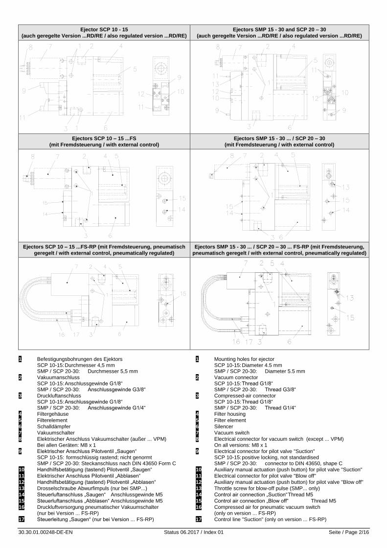
1.1 Ejektor SMP
Saugvermögen / Suction capacity Vakuum / Vacuum Luftverbrauch / Air consumption
Technische Daten / Technical Data
Typ / Type
Düsen- /
Nozzle
Max. Vakuum Max. vacuum
Max. Saugvermögen Max. suction capacity
Betriebsdruck Operating pressure
Gesamtgewicht / Total weight
SMP 15 1.5 mm 85 % 65 l/min 5 ... 6 bar 0,465 kg
SMP 20 2 mm 85 % 116 l/min 5 ... 6 bar 0,465 kg
SMP 25 2.5 mm 85 % 161 l/min 5 ... 6 bar 0,485 kg
SMP 30 3 mm 85 % 200 l/min 5 ... 6 bar 0,485 kg
Saugvermögen bei verschiedenen Evakuierungsgraden in l/min / Suction capacity at various degrees of evacuation in l/min
Typ -50 -100 -200 -300 -400 -500 -600 -700 -800
SMP 15 62 58 50 41 32 21 16 9 4
SMP 20 108 101 90 78 63 48 36 18 5
SMP 25 149 136 123 107 86 66 49 25 7
SMP 30 184 168 153 132 107 82 61 31 9
Luftverbrauch und Schallpegel / Air consumption and noise level
Luftverbrauch in Nl/min bei 5 bar Speisedruck / Air consumption in Nl/min at a supply pressure of 5 bar
Schallpegel bei Saugen / Noise level during suction
Typ / Type Saugen / Evacuating
Abblasen min. / Blowing off, min.
Abblasen max. / Blowing off, max.
frei / Without load
angesaugt / With load attached
SMP 15 117 170 250 74 74
SMP 20 190 170 250 78 76
SMP 25 310 170 250 82 72
SMP 30 420 170 250 82 82
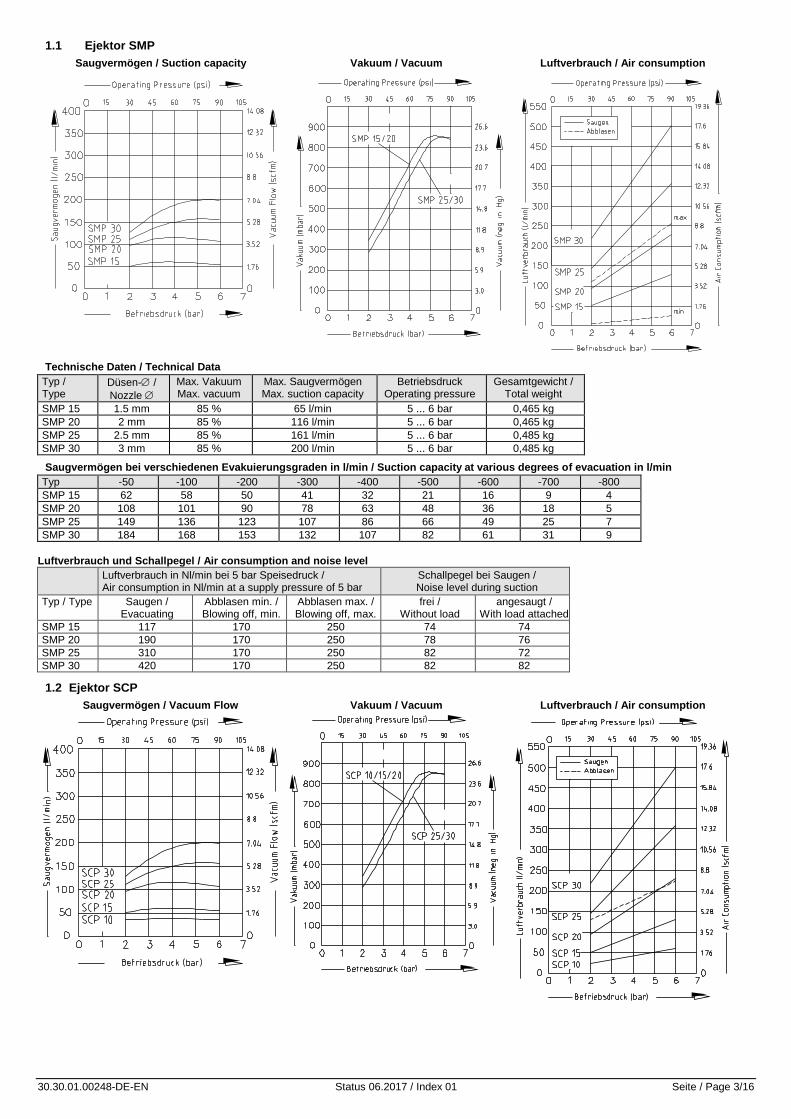
1.2 Ejektor SCP
Saugvermögen / Vacuum Flow Vakuum / Vacuum Luftverbrauch / Air consumption
30.30.01.00248-DE-EN Status 06.2017 / Index 01 Seite / Page 4/16
Technische Daten / Technical Data
Typ / Type Düsen- /
Nozzle
Max. Vakuum Max. vacuum
Max. Saugvermögen Max. Suction capacity
Betriebsdruck Operating pressure
Gesamtgewicht / Total weight
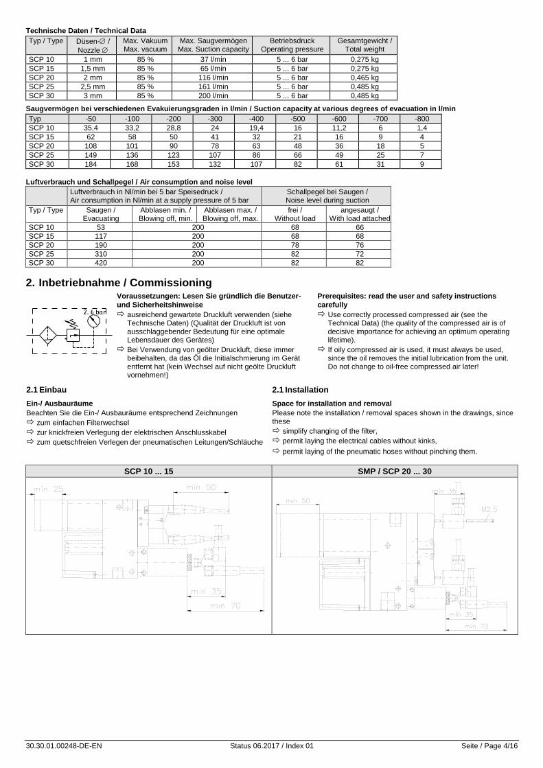
SCP 10 1 mm 85 % 37 l/min 5 ... 6 bar 0,275 kg
SCP 15 1,5 mm 85 % 65 l/min 5 ... 6 bar 0,275 kg
SCP 20 2 mm 85 % 116 l/min 5 ... 6 bar 0,465 kg
SCP 25 2,5 mm 85 % 161 l/min 5 ... 6 bar 0,485 kg
SCP 30 3 mm 85 % 200 l/min 5 ... 6 bar 0,485 kg
Saugvermögen bei verschiedenen Evakuierungsgraden in l/min / Suction capacity at various degrees of evacuation in l/min
Typ -50 -100 -200 -300 -400 -500 -600 -700 -800
SCP 10 35,4 33,2 28,8 24 19,4 16 11,2 6 1,4
SCP 15 62 58 50 41 32 21 16 9 4
SCP 20 108 101 90 78 63 48 36 18 5
SCP 25 149 136 123 107 86 66 49 25 7
SCP 30 184 168 153 132 107 82 61 31 9
Luftverbrauch und Schallpegel / Air consumption and noise level
Luftverbrauch in Nl/min bei 5 bar Speisedruck / Air consumption in Nl/min at a supply pressure of 5 bar
Schallpegel bei Saugen / Noise level during suction
Typ / Type Saugen / Evacuating
Abblasen min. / Blowing off, min.
Abblasen max. / Blowing off, max.
frei / Without load
angesaugt / With load attached
SCP 10 53 200 68 66
SCP 15 117 200 68 68
SCP 20 190 200 78 76
SCP 25 310 200 82 72
SCP 30 420 200 82 82
2. Inbetriebnahme / Commissioning
Voraussetzungen: Lesen Sie gründlich die Benutzer-
und Sicherheitshinweise
ausreichend gewartete Druckluft verwenden (siehe Technische Daten) (Qualität der Druckluft ist von ausschlaggebender Bedeutung für eine optimale Lebensdauer des Gerätes)
Bei Verwendung von geölter Druckluft, diese immer beibehalten, da das Öl die Initialschmierung im Gerät entfernt hat (kein Wechsel auf nicht geölte Druckluft vornehmen!)
Prerequisites: read the user and safety instructions
carefully
Use correctly processed compressed air (see the Technical Data) (the quality of the compressed air is of decisive importance for achieving an optimum operating lifetime).
If oily compressed air is used, it must always be used, since the oil removes the initial lubrication from the unit. Do not change to oil-free compressed air later!
2.1 Einbau
Ein-/ Ausbauräume
Beachten Sie die Ein-/ Ausbauräume entsprechend Zeichnungen
zum einfachen Filterwechsel
zur knickfreien Verlegung der elektrischen Anschlusskabel
zum quetschfreien Verlegen der pneumatischen Leitungen/Schläuche
2.1 Installation
Space for installation and removal
Please note the installation / removal spaces shown in the drawings, since these
simplify changing of the filter,
permit laying the electrical cables without kinks,
permit laying of the pneumatic hoses without pinching them.
SCP 10 ... 15 SMP / SCP 20 ... 30
30.30.01.00248-DE-EN Status 06.2017 / Index 01 Seite / Page 5/16
2.2 Elektrischer Anschluss
Befestigen Sie die zugehörigen Stecker bzw. Kabel an den Magnetventilen und dem Vakuumschalter (sofern vorhanden).
Die zum jeweiligen Gerät passenden Stecker bzw. Kabel entnehmen Sie bitte der nachfolgenden Zubehörtabelle (Pkt.5)
2.2 Electrical Connections
Connect the related plugs and/or cables to the solenoid valves and the vacuum switch (if fitted).
See the table of accessories in Section 5 for the correct plug and/or cable for each unit:
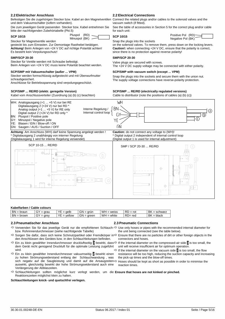
SCP 10/15
Stecker für Magnetventile werden gesteckt bis zum Einrasten. Zur Demontage Rasthebel betätigen.
Achtung! Beim Anlegen von +24 V DC auf richtige Polarität achten! Es besteht kein Verpolungsschutz!
SCP 10/15
Snap the plugs into the sockets on the solenoid valves. To remove them, press down on the locking levers.
Caution!: when connecting +24 V DC, ensure that the polarity is correct, since there is no protection against reverse polarity!
SMP/SCP 20-30
Stecker für Ventile werden mit Schraube befestigt. Beim Anlegen von +24 V DC muss keine Polarität beachtet werden.
SMP/SCP 20-30
Valve plugs are secured with screws. The +24 V DC supply voltage may be connected with either polarity.
SCP/SMP mit Vakuumschalter (außer ... VPM)
Stecker werden formschlüssig aufgesteckt und mit Überwurfmutter schraubgesichert. Anschlüsse für Betriebsspannung sind verpolungsgeschützt.
SCP/SMP with vacuum switch (except ... VPM)
Snap the plugs into the sockets and secure them with the union nut. The supply voltage connections have reverse-polarity protection.
SCP/SMP ... RE/RD (elektr. geregelte Version)
Kabel vom Anschlussverteiler (Zuordnung (a) (b) (c) beachten)
SCP/SMP ... RE/RD (electrically regulated versions)
Cable to distributor (note the positions of cables (a) (b) (c))
WH: Analogausgang (+1 ... +5 V) nur bei RE Digitalausgang 2 (+24 V) nur bei RD * Analog output (+1 ... +5 V) for RE only Digital output 2 (+24 V) for RD only * BN: Pluspol / Positive pole GY: Minuspol / Negative pole YE: Blasen / EIN / Blow-off / ON GN: Saugen / AUS / Suction / OFF
Achtung: Am Anschluss (WH) darf keine Spannung angelegt werden ! Caution: do not connect any voltage to (WH)! * Digitalausgang 2 unabhängig von interner Regelung * Digital output 2 independent of internal control loop (Digitalausgang 1 wird für interne Regelung verwendet) (Digital output 1 is used for internal adjustment)
Kabelfarben / Cable colours
BN = braun GY = grau YE = gelb GN = grün WH = weiss RD = rot BK = schwarz
BN = brown GY = grey YE = yellow GN = green WH = white RD= red BK = black
2.3 Pneumatischer Anschluss
Verwenden Sie für das jeweilige Gerät nur die empfohlenen Schlauch- bzw. Rohrinnendurchmesser (siehe nachfolgende Tabelle)
Sorgen Sie dafür, dass sich keine Schmutzpartikel oder Fremdkörper in den Anschlüssen des Gerätes bzw. in den Schlauchleitungen befinden.
Ein zu klein gewählter Innendurchmesser druckluftseitig 3 bewirkt, dass dem Gerät nicht genügend Druckluft für die optimale Leistung zugeführt wird.
Ein zu klein gewählter Innendurchmesser vakuumseitig 2 bewirkt einen zu hohen Strömungswiderstand entlang der Schlauchwandung , was sich negativ auf die Saugleistung und damit auf die Ansaugzeiten auswirkt, gleichzeitig bewirkt der hohe Strömungswiderstand auch eine Verlängerung der Abblaszeiten.
Schlauchleitungen sollten möglichst kurz verlegt werden, um die Reaktionszeiten möglichst klein zu halten.
Schlauchleitungen knick- und quetschfrei verlegen.
2.3 Pneumatic Connections
Use only hoses or pipes with the recommended internal diameter for the unit being connected (see the table below).
Ensure that there are no particles of dirt or other foreign objects in the connectors and hoses.
If the internal diameter on the compressed-air side 3 is too small, the unit will receive insufficient air for optimum operation.
If the internal diameter on the vacuum side 2 is too small, the flow resistance will be too high, reducing the suction capacity and increasing the pick-up times and the blow-off times.
Hoses should be kept as short as possible in order to minimise the reaction times.
Ensure that hoses are not kinked or pinched.
SMP / SCP 20-30 ... RE/RD SCP 10-15 ... RE/RD
Pluspol (RD) Minuspol (BK)
Interne Regelung / Internal control loop
Positive Pol (RD) Negative Pol (BK)
30.30.01.00248-DE-EN Status 06.2017 / Index 01 Seite / Page 6/16
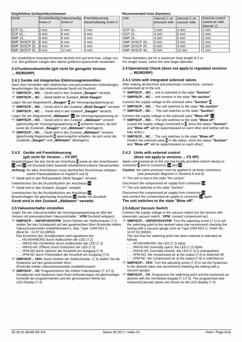
Empfohlene Schlauchdurchmesser Recommended hose diameters
Gerät Druckluftseitig
Innen-
Vakuumseitig
Innen-
Fremdsteuerung
steuerluftseitig Innen-
Unit Internal on pressure side
Internal on vacuum side
External control control air side
internal -
SCP 10... 2 mm 4 mm 2 mm SCP 10... 2 mm 4 mm 2 mm
SCP 15... 4 mm 6 mm 2 mm SCP 15... 4 mm 6 mm 2 mm
SMP 15... 4 mm 6 mm 2 mm SMP 15... 4 mm 6 mm 2 mm
SMP 20/SCP 20... 6 mm 9 mm 2 mm SMP 20/SCP 20... 6 mm 9 mm 2 mm
SMP 25/SCP 25... 9 mm 9 mm 2 mm SMP 25/SCP 25... 9 mm 9 mm 2 mm
SMP 30/SCP 30... 9 mm 12 mm 2 mm SMP 30/SCP 30... 9 mm 12 mm 2 mm
Der empfohlene Innendurchmesser bezieht sich auf eine max. Länge von 2 m. Bei größeren Längen den nächst größeren Querschnitt verwenden
2.4 Funktionskontrolle (gilt nicht für geregelte Version
... RE/RD/RP)
2.4.1 Geräte mit integrierten Elektromagnetventilen
Nach dem Herstellen aller elektrischen und pneumatischen Verbindungen beaufschlagen Sie das entsprechende Gerät mit Druckluft.
SMP/SCP... NO...: Gerät wird in den Zustand „Saugen“ versetzt.
SMP/SCP... NC...: Gerät bleibt im Zustand „Nicht Saugen“.
Legen Sie am Magnetventil „Saugen“ 9 die Versorgungsspannung an.
SMP/SCP... NO...: Gerät wird in den Zustand „Nicht Saugen“ versetzt
SMP/SCP... NC...: Gerät wird in den Zustand „Saugen“ versetzt.
Legen Sie am Magnetventil „Abblasen“ 11 die Versorgungsspannung an.
SMP/SCP... NO...: Gerät wird in den Zustand „Abblasen“ versetzt
(gleichzeitig die Versorgungsspannung an 9 anstehen lassen, da sich
sonst die Zustände „Saugen“ und „Abblasen“ überlagern).
SMP/SCP... NC...: Gerät wird in den Zustand „Abblasen“ versetzt.
(gleichzeitig Magnetventil 9 spannungsfrei schalten, da sich sonst die
Zustände „Saugen“ und „Abblasen“ überlagern).
These diameters are for a maximum hose length of 2 m. For longer hoses, select the next larger diameter.
2.4 Operational Check (does not apply to regulated versions
... RE/RD/RP)
2.4.1 Units with integrated solenoid valves
After making all electrical and pneumatic connections, connect compressed air to the unit.
SMP/SCP... NO...: unit is switched to the state "Suction".
SMP/SCP... NC...: unit remains in the state "No suction".
Connect the supply voltage to the solenoid valve "Suction" 9.
SMP/SCP... NO...: The unit switches to the state "No suction".
SMP/SCP... NC...: The unit switches to the state "Suction".
Connect the supply voltage to the solenoid valve "Blow off" 11.
SMP/SCP... NO...: The unit switches to the state "Blow off".
(Leave the supply voltage connected to 9, since the states "Suction"
and "Blow off" will be superimposed on each other and neither will be
fully active.)
SMP/SCP... NC...: The unit switches to the state "Blow off".
(Switch the solenoid valve 9 in idle status, since the states "Suction"
and "Blow off" will be superimposed on each other)
2.4.2 Geräte mit Fremdsteuerung
(gilt nicht für Version ... FS RP)
Beaufschlagen Sie das Gerät am Anschluss 3 sowie an den Anschlüssen
14 und 15 mit Druckluft (über bauseits erforderliche externe Steuerventile).
Achtung: An allen Anschlüssen muss identisches Druckniveau anliegen (siehe Pneumatikpläne im Kapitel 8 und 9)
Gerät wird in den Ruhezustand „Nicht Saugen“ versetzt.
Unterbrechen Sie die Druckluftzufuhr am Anschluss 14
Gerät wird in den Zustand „Saugen“ versetzt.
Unterbrechen Sie die Druckluftzufuhr am Anschluss 15.
Beaufschlagen Sie gleichzeitig Anschluss 14 wieder mit Druckluft.
Gerät wird in den Zustand „Abblasen“ versetzt.
2.4.2 Units with external control
(does not apply to versions ... FS RP)
Apply compressed air to the unit (via locally provided control valves) to
connector 3 and to connectors 14 and 15.
Caution: the same pressure must be applied to all three connectors (see pneumatic diagrams in Sections 8 and 9).
The unit is now in the state "No suction".
Disconnect the compressed air supply from connector 14.
The unit switches to the state "Suction".
Disconnect the compressed air supply from connector 15
and connect the compressed air supply to connector 14 again.
The unit switches to the state "Blow off".
2.5 Vakuumschalter einstellen
Legen Sie am Vakuumschalter die Versorgungsspannung an (Bei der
Version mit pneumatischem Vakuumschalter ..VPM Druckluft anlegen).
SMP/SCP... VM/VE/VEH/VPM: Durch Drehen der Stellschraube (7.1) stellen Sie den Schaltpunkt auf den gewünschten Wert (Kontrolle mittels Vakuummanometer empfehlenswert z. Bsp. Type: VAM 63/1 U (Best-Nr.: 10.07.02.00004) Das Erreichen des Schaltpunktes wird signalisiert bei: - ... VE/VEH/RE/RD durch Aufleuchten der LED (7.2) - ... VM/VD-NO (Schließer) durch Aufleuchten der LED (7.2) - ... VM/VD-NC (Öffner) durch Erlöschen der LED (7.2) - ... VPM-NO durch Sperren der Druckluft am Ausgang (7.6) - ... VPM-NC durch Freischalten der Druckluft am Ausgang (7.6)
SMP/SCP... VEH: Durch Drehen der Stellschraube (7.3) stellen Sie die Hysterese auf den gewünschten Wert. (Kontrolle mittels Vakuummanometer empfehlenswert)
SMP/SCP... VD: Programmieren Sie mittels Folientastatur (7.1/7.3) Schaltpunkt und Hysterese nach Ihren Anforderungen mit gleichzeitiger Kontrolle der programmierten und der gemessenen Werte am LED-Display (7.4)
2.5 Adjust Vacuum Switch
Connect the supply voltage to the vacuum switch (on the version with
pneumatic vacuum switch ..VPM, connect compressed air).
SMP/SCP... VM/VE/VEH/VPM: Turn the adjusting screw (7.1) to set the switching point to the desired value (we recommend checking the setting with a vacuum gauge such as Type VAM 63/1 U, Order No.: 10.07.02.00004). The fact that the switching point has been reached is indicated as follows: - ... VE/VEH/RE/RD: the LED (7.2) lights - ... VM/VD-NO (normally open): the LED (7.2) lights - ... VM/VD-NC (normally closed): the LED (7.2) is extinguished - ... VPM-NO: the compressed air at the output (7.6) is switched off - ... VPM-NC: the compressed air at the output (7.6) is switched on
SMP/SCP... VEH: Turn the adjusting screw (7.3) to set the hysteresis to the desired value (we recommend checking the setting with a vacuum gauge).
SMP/SCP... VD: Programme the switching point and the hysteresis as desired with the membrane keypad (7.1/7.3). The programmed and measured (actual) values are shown on the LED display (7.4)
30.30.01.00248-DE-EN Status 06.2017 / Index 01 Seite / Page 7/16
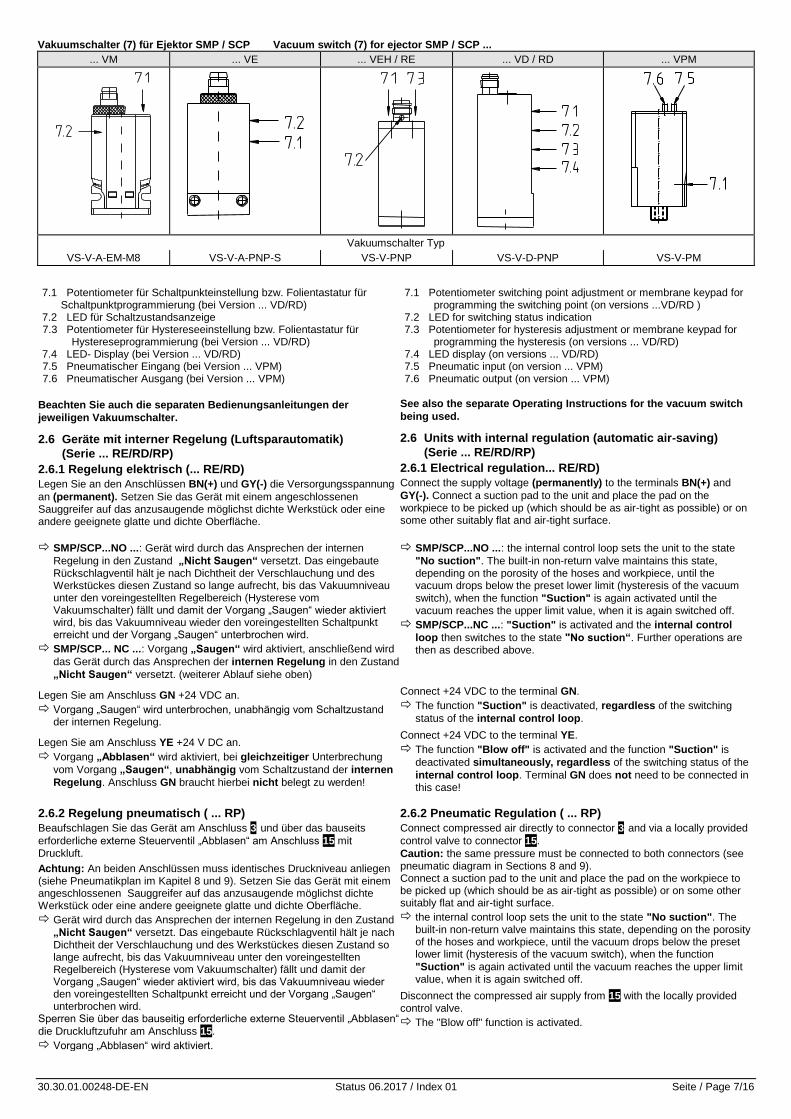
Vakuumschalter (7) für Ejektor SMP / SCP Vacuum switch (7) for ejector SMP / SCP ...
... VM ... VE ... VEH / RE ... VD / RD ... VPM
Vakuumschalter Typ
VS-V-A-EM-M8 VS-V-A-PNP-S VS-V-PNP VS-V-D-PNP VS-V-PM
7.1 Potentiometer für Schaltpunkteinstellung bzw. Folientastatur für Schaltpunktprogrammierung (bei Version ... VD/RD)
7.2 LED für Schaltzustandsanzeige 7.3 Potentiometer für Hystereseeinstellung bzw. Folientastatur für
Hystereseprogrammierung (bei Version ... VD/RD) 7.4 LED- Display (bei Version ... VD/RD) 7.5 Pneumatischer Eingang (bei Version ... VPM) 7.6 Pneumatischer Ausgang (bei Version ... VPM)
Beachten Sie auch die separaten Bedienungsanleitungen der
jeweiligen Vakuumschalter.
2.6 Geräte mit interner Regelung (Luftsparautomatik)
(Serie ... RE/RD/RP)
2.6.1 Regelung elektrisch (... RE/RD)
Legen Sie an den Anschlüssen BN(+) und GY(-) die Versorgungsspannung
an (permanent). Setzen Sie das Gerät mit einem angeschlossenen Sauggreifer auf das anzusaugende möglichst dichte Werkstück oder eine andere geeignete glatte und dichte Oberfläche.
7.1 Potentiometer switching point adjustment or membrane keypad for programming the switching point (on versions ...VD/RD )
7.2 LED for switching status indication 7.3 Potentiometer for hysteresis adjustment or membrane keypad for
programming the hysteresis (on versions ... VD/RD) 7.4 LED display (on versions ... VD/RD) 7.5 Pneumatic input (on version ... VPM) 7.6 Pneumatic output (on version ... VPM)
See also the separate Operating Instructions for the vacuum switch
being used.
2.6 Units with internal regulation (automatic air-saving)
(Serie ... RE/RD/RP)
2.6.1 Electrical regulation... RE/RD)
Connect the supply voltage (permanently) to the terminals BN(+) and
GY(-). Connect a suction pad to the unit and place the pad on the workpiece to be picked up (which should be as air-tight as possible) or on some other suitably flat and air-tight surface.
SMP/SCP...NO ...: Gerät wird durch das Ansprechen der internen
Regelung in den Zustand „Nicht Saugen“ versetzt. Das eingebaute Rückschlagventil hält je nach Dichtheit der Verschlauchung und des Werkstückes diesen Zustand so lange aufrecht, bis das Vakuumniveau unter den voreingestellten Regelbereich (Hysterese vom Vakuumschalter) fällt und damit der Vorgang „Saugen“ wieder aktiviert wird, bis das Vakuumniveau wieder den voreingestellten Schaltpunkt erreicht und der Vorgang „Saugen“ unterbrochen wird.
SMP/SCP... NC ...: Vorgang „Saugen“ wird aktiviert, anschließend wird
das Gerät durch das Ansprechen der internen Regelung in den Zustand
„Nicht Saugen“ versetzt. (weiterer Ablauf siehe oben)
SMP/SCP...NO ...: the internal control loop sets the unit to the state
"No suction". The built-in non-return valve maintains this state, depending on the porosity of the hoses and workpiece, until the vacuum drops below the preset lower limit (hysteresis of the vacuum
switch), when the function "Suction" is again activated until the vacuum reaches the upper limit value, when it is again switched off.
SMP/SCP...NC ...: "Suction" is activated and the internal control
loop then switches to the state "No suction“. Further operations are then as described above.
Legen Sie am Anschluss GN +24 VDC an.
Vorgang „Saugen“ wird unterbrochen, unabhängig vom Schaltzustand der internen Regelung.
Legen Sie am Anschluss YE +24 V DC an.
Vorgang „Abblasen“ wird aktiviert, bei gleichzeitiger Unterbrechung
vom Vorgang „Saugen“, unabhängig vom Schaltzustand der internen
Regelung. Anschluss GN braucht hierbei nicht belegt zu werden!
Connect +24 VDC to the terminal GN.
The function "Suction" is deactivated, regardless of the switching
status of the internal control loop.
Connect +24 VDC to the terminal YE.
The function "Blow off" is activated and the function "Suction" is
deactivated simultaneously, regardless of the switching status of the
internal control loop. Terminal GN does not need to be connected in this case!
2.6.2 Regelung pneumatisch ( ... RP)
Beaufschlagen Sie das Gerät am Anschluss 3 und über das bauseits
erforderliche externe Steuerventil „Abblasen“ am Anschluss 15 mit Druckluft.
Achtung: An beiden Anschlüssen muss identisches Druckniveau anliegen (siehe Pneumatikplan im Kapitel 8 und 9). Setzen Sie das Gerät mit einem angeschlossenen Sauggreifer auf das anzusaugende möglichst dichte Werkstück oder eine andere geeignete glatte und dichte Oberfläche.
Gerät wird durch das Ansprechen der internen Regelung in den Zustand
„Nicht Saugen“ versetzt. Das eingebaute Rückschlagventil hält je nach Dichtheit der Verschlauchung und des Werkstückes diesen Zustand so lange aufrecht, bis das Vakuumniveau unter den voreingestellten Regelbereich (Hysterese vom Vakuumschalter) fällt und damit der Vorgang „Saugen“ wieder aktiviert wird, bis das Vakuumniveau wieder den voreingestellten Schaltpunkt erreicht und der Vorgang „Saugen“ unterbrochen wird.
Sperren Sie über das bauseitig erforderliche externe Steuerventil „Abblasen“
die Druckluftzufuhr am Anschluss 15.
Vorgang „Abblasen“ wird aktiviert.
2.6.2 Pneumatic Regulation ( ... RP)
Connect compressed air directly to connector 3 and via a locally provided
control valve to connector 15.
Caution: the same pressure must be connected to both connectors (see pneumatic diagram in Sections 8 and 9). Connect a suction pad to the unit and place the pad on the workpiece to be picked up (which should be as air-tight as possible) or on some other suitably flat and air-tight surface.
the internal control loop sets the unit to the state "No suction". The built-in non-return valve maintains this state, depending on the porosity of the hoses and workpiece, until the vacuum drops below the preset lower limit (hysteresis of the vacuum switch), when the function
"Suction" is again activated until the vacuum reaches the upper limit value, when it is again switched off.
Disconnect the compressed air supply from 15 with the locally provided control valve.
The "Blow off" function is activated.
30.30.01.00248-DE-EN Status 06.2017 / Index 01 Seite / Page 8/16
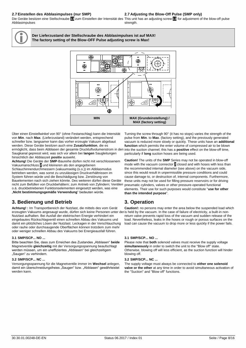
2.7 Einstellen des Abblasimpulses (nur SMP)
Die Geräte besitzen eine Stellschraube 13 zum Einstellen der Intensität des Abblasimpulses
2.7 Adjusting the Blow-Off Pulse (SMP only)
This unit has an adjusting screw 13 for adjustment of the blow-off pulse strength.
Der Lieferzustand der Stellschraube des Abblasimpulses ist auf MAX!
The factory setting of the Blow-OFF Pulse adjusting screw is Max!
MIN MAX (Grundeinstellung) /
MAX (factory setting)
Über einen Einstellwinkel von 90° (ohne Festanschlag) kann die Intensität
von Min. nach Max. (Lieferzustand) verändert werden, entsprechend schneller bzw. langsamer kann das vorher erzeugte Vakuum abgebaut
werden. Diese Geräte besitzen auch eine Zusatzfunktion, die es ermöglicht, dass beim Abblasen der gesamte Druckluftvolumenstrom in den
Saugkanal gepresst wird, was sich vor allem bei langen Saugleitungen
hinsichtlich der Abblaszeit positiv auswirkt.
Achtung! Die Geräte der SMP-Baureihe dürfen nicht mit verschlossenem
Vakuumanschluss 2 und kleineren als den angegebenen Schlauchinnendurchmessern (vakuumseitig (s.o.)) im Abblasmodus betrieben werden, was sonst zu unzulässigen Druckverhältnissen im System führen würde und die Beschädigung bzw. Zerstörung von Bauelementen nach sich ziehen könnte. Des weiteren dürfen diese Geräte nicht zum Befüllen von Druckbehältern; zum Antrieb von Zylindern; Ventilen o.ä. druckbetriebenen Funktionselementen eingesetzt werden, was eine
„Nicht bestimmungsgemäße Verwendung“ bedeuten würde.
Turning the screw through 90° (it has no stops) varies the strength of the
pulse from Min. to Max. (factory setting), and the previously generated
vacuum is reduced more slowly or quickly. These units have an additional
function which permits the enter volume of compressed air to be blown
into the suction channel; this has a positive effect on the blow-off time,
particularly if long suction hoses are being used.
Caution! The units of the SMP Series may not be operated in blow-off
mode with the vacuum connector 2 closed and with hoses with less than
the recommended internal diameter (see above) on the vacuum side,
since this would result in unpermissible pressure conditions and could
cause damage to, or destruction of, internal components. Furthermore,
these units may not be used for filling pressure reservoirs or for driving
pneumatic cylinders, valves or other pressure-operated functional
elements. Their use for such purposes would constitute "use for other
than the intended purpose".
3. Bedienung und Betrieb Achtung! : Im Transportbereich der Nutzlast, die mittels des vom Gerät erzeugten Vakuums angesaugt wurde, dürfen sich keine Personen unter der Nutzlast aufhalten. Bei Ausfall der elektrischen Energie verhindert ein eingebautes Rückschlagventil einen schnellen Abbau des Vakuums und damit ein plötzliches Lösen der Nutzlast. Leckagen in der Verschlauchung oder rauhe oder durchsaugende Oberflächen können trotzdem zum mehr oder weniger schnellen Abbau des Vakuums bei Energieausfall führen.
3. Operation Caution!: no persons may enter the area below the suspended load which is held by the vacuum. In the case of failure of electricity, a built-in non-return valve prevents rapid loss of the vacuum and sudden release of the load. Nevertheless, leaks in the hoses or rough or porous surfaces on the load can cause the vacuum to drop more or less quickly if the power fails.
3.1 SMP/SCP... NO ...
Bitte beachten Sie, dass zum Erreichen des Zustandes „Abblasen“ beide
Magnetventile gleichzeitig mit der Versorgungsspannung beaufschlagt werden müssen, um ein uneffizientes „Abblasen“ bei gleichzeitigem „Saugen“ zu verhindern.
3.1 SMP/SCP... NO ...
Please note that both solenoid valves must receive the supply voltage
simultaneously in order to switch the unit to the "Blow off" state. Otherwise, blowing off will less efficient, as the suction function will hinder blowing off.
3.2 SMP/SCP... NC ...
Versorgungsspannung für die Magnetventile immer im Wechsel anlegen, damit ein überschneidungsfreies „Saugen“ bzw. „Abblasen“ gewährleistet werden kann.
3.2 SMP/SCP... NC ...
The supply voltage must always be connected to either one solenoid
valve or the other at any time in order to avoid simultaneous activation of the "Suction" and "Blow off" functions.
30.30.01.00248-DE-EN Status 06.2017 / Index 01 Seite / Page 9/16
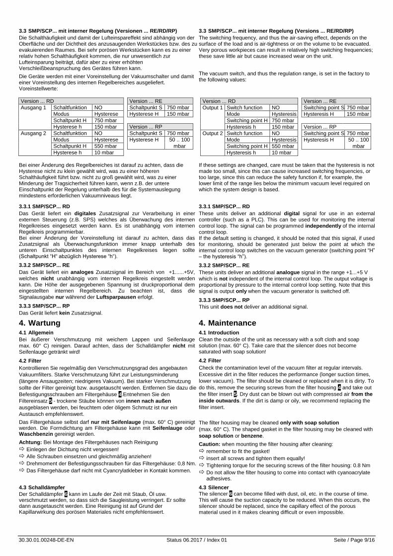
3.3 SMP/SCP... mit interner Regelung (Versionen ... RE/RD/RP)
Die Schalthäufigkeit und damit der Lufteinspareffekt sind abhängig von der Oberfläche und der Dichtheit des anzusaugenden Werkstückes bzw. des zu evakuierenden Raumes. Bei sehr porösen Werkstücken kann es zu einer relativ hohen Schalthäufigkeit kommen, die nur unwesentlich zur Lufteinsparung beiträgt, dafür aber zu einer erhöhten Verschleißbeanspruchung des Gerätes führen kann.
Die Geräte werden mit einer Voreinstellung der Vakuumschalter und damit einer Voreinstellung des internen Regelbereiches ausgeliefert. Voreinstellwerte:
3.3 SMP/SCP... mit interner Regelung (Versions ... RE/RD/RP)
The switching frequency, and thus the air-saving effect, depends on the surface of the load and is air-tightness or on the volume to be evacuated. Very porous workpieces can result in relatively high switching frequencies; these save little air but cause increased wear on the unit.
The vacuum switch, and thus the regulation range, is set in the factory to the following values:
Version ... RD Version ... RE
Ausgang 1 Schaltfunktion NO Schaltpunkt S 750 mbar
Modus Hysterese Hysterese H 150 mbar
Schaltpunkt H 750 mbar
Hysterese h 150 mbar Version ... RP
Ausgang 2 Schaltfunktion NO Schaltpunkt S 750 mbar
Modus Hysterese Hysterese H 50 .. 100
Schaltpunkt H 550 mbar mbar
Hysterese h 10 mbar
Bei einer Änderung des Regelbereiches ist darauf zu achten, dass die Hysterese nicht zu klein gewählt wird, was zu einer höheren Schalthäufigkeit führt bzw. nicht zu groß gewählt wird, was zu einer Minderung der Tragsicherheit führen kann, wenn z.B. der untere Einschaltpunkt der Regelung unterhalb des für die Systemauslegung mindestens erforderlichen Vakuumniveaus liegt.
If these settings are changed, care must be taken that the hysteresis is not made too small, since this can cause increased switching frequencies, or too large, since this can reduce the safety function if, for example, the lower limit of the range lies below the minimum vacuum level required on which the system design is based.
3.3.1 SMP/SCP... RD
Das Gerät liefert ein digitales Zusatzsignal zur Verarbeitung in einer externen Steuerung (z.B. SPS) welches als Überwachung des internen Regelkreises eingesetzt werden kann. Es ist unabhängig vom internen Regelkreis programmierbar. Bei einer Änderung der Voreinstellung ist darauf zu achten, dass das Zusatzsignal als Überwachungsfunktion immer knapp unterhalb des unteren Einschaltpunktes des internen Regelkreises liegen sollte (Schaltpunkt “H“ abzüglich Hysterese “h“).
3.3.2 SMP/SCP... RE
Das Gerät liefert ein analoges Zusatzsignal im Bereich von +1......+5V,
welches nicht unabhängig vom internen Regelkreis eingestellt werden kann. Die Höhe der ausgegebenen Spannung ist druckproportional dem eingestellten internen Regelbereich. Zu beachten ist, dass die
Signalausgabe nur während der Luftsparpausen erfolgt.
3.3.3 SMP/SCP... RP
Das Gerät liefert kein Zusatzsignal.
3.3.1 SMP/SCP... RD
These units deliver an additional digital signal for use in an external controller (such as a PLC). This can be used for monitoring the internal
control loop. The signal can be programmed independently of the internal control loop. If the default setting is changed, it should be noted that this signal, if used for monitoring, should be generated just below the point at which the internal control loop switches on the vacuum generator (switching point “H” – the hysteresis “h”).
3.3.2 SMP/SCP... RE
These units deliver an additional analogue signal in the range +1...+5 V
which is not independent of the internal control loop. The output voltage is proportional by pressure to the internal control loop setting. Note that this
signal is output only when the vacuum generator is switched off.
3.3.3 SMP/SCP... RP
This unit does not deliver an additional signal.
4. Wartung 4.1 Allgemein
Bei äußerer Verschmutzung mit weichem Lappen und Seifenlauge
max. 60° C) reinigen. Darauf achten, dass der Schalldämpfer nicht mit Seifenlauge getränkt wird!
4.2 Filter
Kontrollieren Sie regelmäßig den Verschmutzungsgrad des angebauten
Vakuumfilters. Starke Verschmutzung führt zur Leistungsminderung
(längere Ansaugzeiten; niedrigeres Vakuum). Bei starker Verschmutzung
sollte der Filter gereinigt bzw. ausgetauscht werden. Entfernen Sie dazu die
Befestigungsschrauben am Filtergehäuse 4.Entnehmen Sie den
Filtereinsatz 5 - trockene Stäube können von innen nach außen
ausgeblasen werden, bei feuchtem oder öligem Schmutz ist nur ein
Austausch empfehlenswert.
4. Maintenance 4.1 Introduction
Clean the outside of the unit as necessary with a soft cloth and soap solution (max. 60° C). Take care that the silencer does not become saturated with soap solution!
4.2 Filter
Check the contamination level of the vacuum filter at regular intervals.
Excessive dirt in the filter reduces the performance (longer suction times,
lower vacuum). The filter should be cleaned or replaced when it is dirty. To
do this, remove the securing screws from the filter housing 4 and take out
the filter insert 5. Dry dust can be blown out with compressed air from the
inside outwards. If the dirt is damp or oily, we recommend replacing the
filter insert.
Das Filtergehäuse selbst darf nur mit Seifenlauge (max. 60° C) gereinigt werden. Die Formdichtung am Filtergehäuse kann mit Seifenlauge oder Waschbenzin gereinigt werden.
Achtung: Bei Montage des Filtergehäuses nach Reinigung
Einlegen der Dichtung nicht vergessen!
Alle Schrauben einsetzen und gleichmäßig anziehen!
Drehmoment der Befestigungsschrauben für das Filtergehäuse: 0,8 Nm.
Das Filtergehäuse darf nicht mit Cyancrylatkleber in Kontakt kommen.
The filter housing may be cleaned only with soap solution
(max. 60° C). The shaped gasket in the filter housing may be cleaned with
soap solution or benzene.
Caution: when mounting the filter housing after cleaning:
remember to fit the gasket!
insert all screws and tighten them equally!
Tightening torque for the securing screws of the filter housing: 0.8 Nm
Do not allow the filter housing to come into contact with cyanoacrylate adhesives.
4.3 Schalldämpfer
Der Schalldämpfer 6 kann im Laufe der Zeit mit Staub, Öl usw. verschmutzt werden, so dass sich die Saugleistung verringert. Er sollte dann ausgetauscht werden. Eine Reinigung ist auf Grund der Kapillarwirkung des porösen Materiales nicht empfehlenswert.
4.3 Silencer
The silencer 6 can become filled with dust, oil, etc. in the course of time. This will cause the suction capacity to be reduced. When this occurs, the silencer should be replaced, since the capillary effect of the porous material used in it makes cleaning difficult or even impossible.
Version ... RD Version ... RE
Output 1 Switch function NO Switching point S 750 mbar
Mode Hysteresis Hysteresis H 150 mbar
Switching point H 750 mbar
Hysteresis h 150 mbar Version ... RP
Output 2 Switch function NO Switching point S 750 mbar
Mode Hysteresis Hysteresis H 50 .. 100
Switching point H 550 mbar mbar
Hysteresis h 10 mbar
30.30.01.00248-DE-EN Status 06.2017 / Index 01 Seite / Page 10/16
5. Zubehör 5. Accessories Stecker für Magnetventile Plugs for solenoid valves
Steckertyp Für SCP 10 / 15 Plug type for SCP 10 / 15
Stecker mit 3 m Kabel 21.04.06.00086 Plug with 3 m cable 21.04.06.00086
Steckertyp für SMP / SCP 20...30 Plug type for SMP / SCP 20...30
Stecker mit Schutzbeschaltung und 5 m Kabel 21.04.06.00084 Plug with protective circuit and 5 m cable 21.04.06.00084
Stecker mit Schutzbeschaltung ohne Kabel 21.04.06.00085 Plug with protective circuit, without cable 21.04.06.00085
Stecker für Vakuumschalter Plugs for vacuum switches Steckertyp Art.No. Plug type Article No.
Stecker; gerade mit 5 m Kabel 10.06.02.00031 Plug, straight, with 5 m cable
10.06.02.00031
Stecker; 90° mit 5 m Kabel 10.06.02.00032 Plug; 90° with 5 m cable
10.06.02.00032
Staubfilter Bei starkem Schmutzanfall saugseitig oder feinem Staub <50 µm ist ein separater Staubfilter dem Gerät vorzuschalten
Dust filters In very dusty operating conditions, or in the case of fine dust <50 µm, a separate dust filter must be fitted on the inlet side.
Filtertyp Art.No. Geeignet für Ejektor Filter type Article No. Suitable for ejector
F 1/4 10.07.01.00003 SMP / SCP 10-15 ... F 1/4 10.07.01.00003 SMP / SCP 10-15 ...
F3/8 10.07.01.00004 SMP / SCP 20 ... F3/8 10.07.01.00004 SMP / SCP 20 ...
STF 3/4 10.07.01.00007 SMP / SCP 25-30 ... STF 3/4 10.07.01.00007 SMP / SCP 25-30 ...
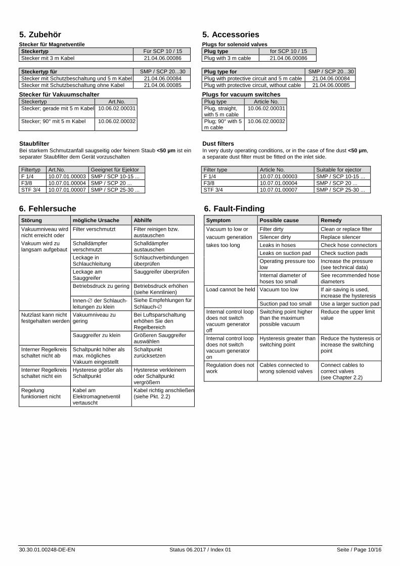
6. Fehlersuche
Störung mögliche Ursache Abhilfe
Vakuumniveau wird nicht erreicht oder
Filter verschmutzt Filter reinigen bzw. austauschen
Vakuum wird zu langsam aufgebaut
Schalldämpfer verschmutzt
Schalldämpfer austauschen
Leckage in Schlauchleitung
Schlauchverbindungen überprüfen
Leckage am Sauggreifer
Sauggreifer überprüfen
Betriebsdruck zu gering Betriebsdruck erhöhen (siehe Kennlinien)
Innen- der Schlauch-leitungen zu klein
Siehe Empfehlungen für
Schlauch-
Nutzlast kann nicht festgehalten werden
Vakuumniveau zu gering
Bei Luftsparschaltung erhöhen Sie den Regelbereich
Sauggreifer zu klein Größeren Sauggreifer auswählen
Interner Regelkreis schaltet nicht ab
Schaltpunkt höher als max. mögliches Vakuum eingestellt
Schaltpunkt zurücksetzen
Interner Regelkreis schaltet nicht ein
Hysterese größer als Schaltpunkt
Hysterese verkleinern oder Schaltpunkt vergrößern
Regelung funktioniert nicht
Kabel am Elektromagnetventil vertauscht
Kabel richtig anschließen (siehe Pkt. 2.2)
6. Fault-Finding
Symptom Possible cause Remedy
Vacuum to low or Filter dirty Clean or replace filter
vacuum generation Silencer dirty Replace silencer
takes too long Leaks in hoses Check hose connectors
Leaks on suction pad Check suction pads
Operating pressure too low
Increase the pressure (see technical data)
Internal diameter of hoses too small
See recommended hose diameters
Load cannot be held Vacuum too low If air-saving is used, increase the hysteresis
Suction pad too small Use a larger suction pad
Internal control loop does not switch vacuum generator off
Switching point higher than the maximum possible vacuum
Reduce the upper limit value
Internal control loop does not switch vacuum generator on
Hysteresis greater than switching point
Reduce the hysteresis or increase the switching point
Regulation does not work
Cables connected to wrong solenoid valves
Connect cables to correct valves (see Chapter 2.2)
30.30.01.00248-DE-EN Status 06.2017 / Index 01 Seite / Page 11/16
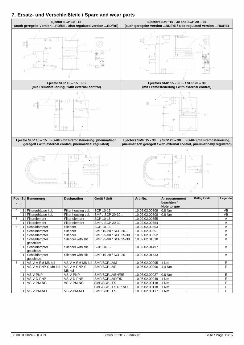
7. Ersatz- und Verschleißteile / Spare and wear parts
Ejector SCP 10 - 15
(auch geregelte Version ...RD/RE / also regulated version ...RD/RE)
Ejectors SMP 15 - 30 and SCP 20 – 30
(auch geregelte Version ...RD/RE / also regulated version ...RD/RE)
Ejector SCP 10 – 15 ...FS
(mit Fremdsteuerung / with external control)
Ejectors SMP 15 - 30 ... / SCP 20 – 30
(mit Fremdsteuerung / with external control)
Ejector SCP 10 – 15 ...FS-RP (mit Fremdsteuerung, pneumatisch
geregelt / with external control, pneumatical regulated)
Ejectors SMP 15 - 30 ... / SCP 20 – 30 ... FS-RP (mit Fremdsteuerung,
pneumatisch geregelt / with external control, pneumatically regulated)
Pos
.
St
.
Benennung Designation Gerät / Unit Art.-No. Anzugsmoment
beachten /
Note torque
Gültig / Valid Legende
4 1 Filtergehäuse kpl. Filter housing cpl. SCP 10-15 10.02.02.00809 0,8 Nm VB
1 Filtergehäuse kpl. Filter housing cpl. SMP / SCP 20-30... 10.02.02.00808 0,8 Nm VB
5 1 Filterelement Filter element SCP 10-15 10.02.02.00655 V
1 Filterelement Filter element SMP / SCP 20-30 10.02.02.00654 V
6 1 Schalldämpfer Silencer SCP 10-15 10.02.02.00653 V
1 Schalldämpfer Silencer SMP 15-20 / SCP 20... 10.02.02.00651 V
1 Schalldämpfer Silencer SMP 25-30 / SCP 25-30... 10.02.02.00652 V
1 Schalldämpfer geschlitzt
Silencer with slit SMP 25-30 / SCP 25-30... 10.02.02.01318 V
1 Schalldämpfer geschlitzt
Silencer with slit SCP 10-15 10.02.02.01497 V
1 Schalldämpfer geschlitzt
Silencer with slit SMP 15-20 / SCP 20 10.02.02.01533 V
7 1 VS-V-A-EM-M8-kpl VS-V-A-EM-M8-kpl SMP/SCP...VM 10.06.02.00095 1 Nm E
1 VS-V-A-PNP-S-M8-kpl VS-V-A-PNP-S-M8-kpl
SMP/SCP...VE 10.06.02.00096 1,4 Nm E
1 VS-V-PNP VS-V-PNP SMP/SCP...VEH/RE 10.06.02.00027 0,8 Nm E
1 VS-V-D-PNP VS-V-D-PNP SMP/SCP...VD/RD 10.06.02.00049 1 Nm E
1 VS-V-PM-NC VS-V-PM-NC SMP/SCP...FS 10.06.02.00118 1 Nm E
SMP/SCP...FS RP-NO 10.06.02.00118 1 Nm E
1 VS-V-PM-NO VS-V-PM-NO SMP/SCP...FS 10.06.02.00117 1 Nm E
30.30.01.00248-DE-EN Status 06.2017 / Index 01 Seite / Page 12/16
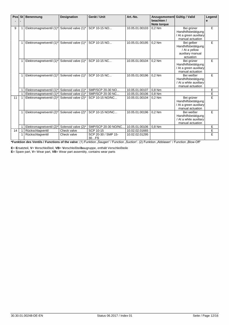
Pos
.
St
.
Benennung Designation Gerät / Unit Art.-No. Anzugsmoment
beachten /
Note torque
Gültig / Valid Legend
e
9 1 Elektromagnetventil (1)* Solenoid valve (1)* SCP 10-15 NO... 10.05.01.00103 0,2 Nm Bei grüner Handhilfsbetätigung / At a green auxiliary
manual actuation
E
1 Elektromagnetventil (1)* Solenoid valve (1)* SCP 10-15 NO... 10.05.01.00195 0,2 Nm Bei gelber Handhilfsbetätigung
/ At a yellow auxiliary manual
actuation
E
1 Elektromagnetventil (1)* Solenoid valve (1)* SCP 10-15 NC... 10.05.01.00104 0,2 Nm Bei grüner Handhilfsbetätigung / At a green auxiliary
manual actuation
E
1 Elektromagnetventil (1)* Solenoid valve (1)* SCP 10-15 NC... 10.05.01.00196 0,2 Nm Bei weißer Handhilfsbetätigung / At a white auxiliary
manual actuation
E
1 Elektromagnetventil (1)* Solenoid valve (1)* SMP/SCP 20-30 NO... 10.05.01.00107 0,8 Nm E
1 Elektromagnetventil (1)* Solenoid valve (1)* SMP/SCP 20-30 NC... 10.05.01.00106 0,8 Nm E
11 1 Elektromagnetventil (2)* Solenoid valve (2)* SCP 10-15 NO/NC... 10.05.01.00104 0,2 Nm Bei grüner Handhilfsbetätigung / At a green auxiliary
manual actuation
E
1 Elektromagnetventil (2)* Solenoid valve (2)* SCP 10-15 NO/NC... 10.05.01.00196 0,2 Nm Bei weißer Handhilfsbetätigung / At a white auxiliary
manual actuation
E
1 Elektromagnetventil (2)* Solenoid valve (2)* SMP/SCP 20-30 NO/NC... 10.05.01.00106 0,8 Nm E
14 1 Rückschlagventil Check valve SCP 10-15 10.02.02.01665 E
1 Rückschlagventil Check valve SCP 20-30 / SMP 15-30…FS
10.02.02.01295 E
*Funktion des Ventils / Functions of the valve: (1) Funktion „Saugen“ / Function „Suction“. (2) Funktion „Abblasen“ / Function „Blow-Off“
E= Ersatzteil, V= Verschleißteil, VB= Verschleißteilbaugruppe, enthält Verschleißteile
E= Spare part, V= Wear part, VB= Wear part assembly, contains wear parts
30.30.01.00248-DE-EN Status 06.2017 / Index 01 Seite / Page 13/16
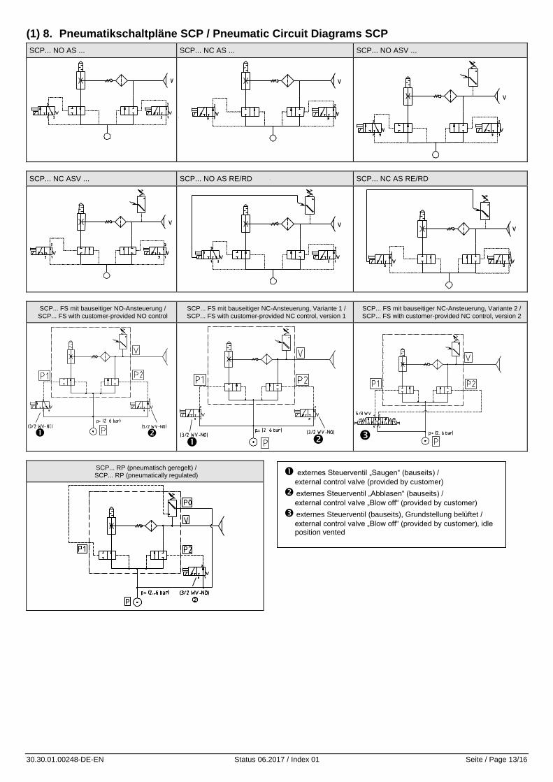
(1) 8. Pneumatikschaltpläne SCP / Pneumatic Circuit Diagrams SCP
SCP... NO AS ... SCP... NC AS ... SCP... NO ASV ...
SCP... NC ASV ... SCP... NO AS RE/RD SCP... NC AS RE/RD
SCP... FS mit bauseitiger NO-Ansteuerung / SCP... FS with customer-provided NO control
SCP... FS mit bauseitiger NC-Ansteuerung, Variante 1 / SCP... FS with customer-provided NC control, version 1
SCP... FS mit bauseitiger NC-Ansteuerung, Variante 2 / SCP... FS with customer-provided NC control, version 2
SCP... RP (pneumatisch geregelt) / SCP... RP (pneumatically regulated)
externes Steuerventil „Saugen“ (bauseits) /
external control valve (provided by customer)
externes Steuerventil „Abblasen“ (bauseits) /
external control valve „Blow off“ (provided by customer)
externes Steuerventil (bauseits), Grundstellung belüftet /
external control valve „Blow off“ (provided by customer), idle position vented
30.30.01.00248-DE-EN Status 06.2017 / Index 01 Seite / Page 14/16
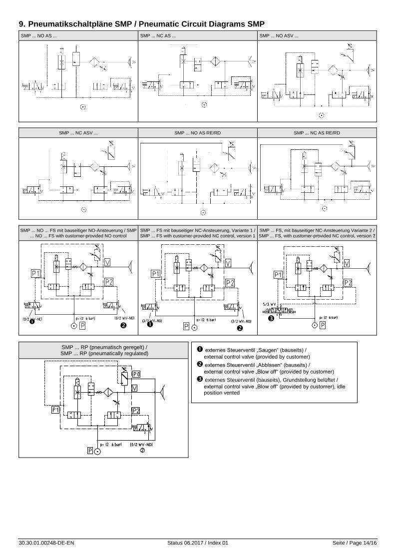
9. Pneumatikschaltpläne SMP / Pneumatic Circuit Diagrams SMP
SMP ... NO AS ... SMP ... NC AS ... SMP ... NO ASV ...
SMP ... NC ASV ... SMP ... NO AS RE/RD SMP ... NC AS RE/RD
SMP ... NO ... FS mit bauseitiger NO-Ansteuerung / SMP ... NO ... FS with customer-provided NO control
SMP ... FS mit bauseitiger NC-Ansteuerung, Variante 1 / SMP ... FS with customer-provided NC control, version 1
SMP ... FS, mit bauseitiger NC-Ansteuerung Variante 2 / SMP ... FS, with customer-provided NC control, version 2
SMP ... RP (pneumatisch geregelt) / SMP ... RP (pneumatically regulated)
externes Steuerventil „Saugen“ (bauseits) /
external control valve (provided by customer)
externes Steuerventil „Abblasen“ (bauseits) /
external control valve „Blow off“ (provided by customer)
externes Steuerventil (bauseits), Grundstellung belüftet /
external control valve „Blow off“ (provided by customer), idle position vented
30.30.01.00248-DE-EN Status 06.2017 / Index 01 Seite / Page 15/16
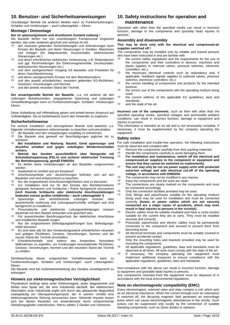
10. Benutzer- und Sicherheitsanweisungen Unzulässiger Betrieb mit anderen Medien kann zu Funktionsstörungen, Schäden und Verletzungen – auch Lebensgefahr – führen.
Montage / Demontage Nur im spannungslosem und drucklosem Zustand zulässig ! Die Bauteile dürfen nur von zuverlässigem Fachpersonal eingesetzt werden, das unter anderem geschult und vertraut ist mit: den neuesten geltenden Sicherheitsregeln und Anforderungen beim
Einsatz der Bauteile und deren Steuerungen in Geräten, Maschinen und Anlagen (für Magnetventile, Druckschalter, elektronischen Steuerungen etc.)
und deren erforderlicher elektrischer Ansteuerung, z.B. Redundanzen und ggf. Rückmeldungen (für Elektromagnetventile, Druckschalter, elektronischen Steuerungen etc.)
und dem sachgerechtem Umgang mit Bauteilen und Produkten für deren Zweckbestimmung
und deren sachgerechtem Einsatz mit dem Betriebsmedium und den jeweils erforderlichen, neuesten geltenden EG-Richtlinien,
Gesetzen, Verordnungen und Normen und den jeweils neuesten Stand der Technik.
Der unsachgemäße Betrieb der Bauteile, u.a. mit anderen als den zulässigen Betriebsmedien, angegebenen Spannung und zulässigen Umweltbedingungen kann zu Funktionsstörungen, Schäden, Verletzungen führen. Diese Aufstellung soll Hilfestellung geben und erhebt keinen Anspruch auf Vollständigkeit. Sie ist bedarfsweise durch den Anwender zu ergänzen.
Sicherheitshinweise Für sichere Installation und störungsfreien Betrieb sind weiterhin u.a. folgende Verhaltensweisen nebeneinander zu beachten und einzuhalten: die Bauteile sind den Verpackungen sorgfältig zu entnehmen. Die Bauteile sind generell vor Beschädigungen jeglicher Art zu
schützen Bei Installation und Wartung: Bauteil, Gerät spannungs- und
druckfrei schalten und gegen unbefugtes Wiedereinschalten sichern.
Betrieb des Gerätes ausschließlich über Netzgeräte mit Schutzkleinspannung (PELV) und sicherer elektrischer Trennung der Betriebsspannung, gemäß EN60204.
Es dürfen keine Veränderungen an den Bauteilen vorgenommen werden.
Sauberkeit im Umfeld und am Einsatzort Anschlusssymbole und –bezeichnungen befinden sich auf den
Bauteilen und sind entsprechend zu beachten Nur die vorgesehenen Anschlussmöglichkeiten sind zu benutzen. Zur Installation sind nur für den Einsatz des Betriebsmediums
geeignete Armaturen und Schläuche / Rohre fachgerecht einzusetzen (sich lösende Schläuche oder elektrische Anschlussleitungen bedeuten extrem großes Unfallrisiko – auch Lebensgefahr !)
Spannungs- und stromführende Leitungen müssen über ausreichende Isolierung und Leitungsquerschnitte verfügen und sind fachgerecht zu installieren
Pneumatische und elektrische Leitungsverbindungen müssen dauerhaft mit dem Bauteil verbunden und gesichert sein.
Für ausreichenden Berührungsschutz der elektrischen Anschlüsse und installierten Bauteile sorgen.
Nur die vorgesehenen Befestigungsbohrungen bzw. Befestigungs-mittel benutzen
Es sind stets alle für den Verwendungszweck erforderlichen neuesten und gültigen Richtlinien, Gesetze, Verordnungen, Normen und der neuste Stand der Technik einzuhalten.
Erforderlichenfalls sind seitens des Anwenders besondere Maßnahmen zu ergreifen, um Forderungen einzuhaltender Richtlinien, Gesetze, Verordnungen, Normen und den neuesten Stand der Technik zu erfüllen.
Nichtbeachtung dieser vorgenannten Verhaltensweisen kann zu Funktionsstörungen, Schäden und Verletzungen –auch Lebensgefahr- führen. Die Bauteile sind bei Außerbetriebstellung des Gerätes umweltgerecht zu entsorgen!
Hinweis zur elektromagnetischen Verträglichkeit Physikalisch bedingt weist jeder Elektromagnet, jedes Magnetventil und Relais eine Spule auf, die eine Induktivität darstellt. Bei elektrischem Abschalten einer Induktivität ergibt sich durch das abbauende Magnetfeld zwangsläufig ein Überspannungsimpuls, der in seinem Umfeld eine elektromagnetische Störung verursachen kann. Störende Impulse lassen sich bei diesen Bauteilen nur anwenderseits durch entsprechende Dämpfungsglieder unterdrücken. Hierzu zählen Z-Dioden und Varistoren.
10. Safety instructions for operation and
maintenance Operation with other than the specified media can result in incorrect function, damage to the components and (possibly fatal) injuries to persons.
Assembly and disassembly This may be done only with the electrical and compressed-air
supplies switched off ! The components may be installed only by reliable and trained persons who have been instructed in and are familiar with: the current safety regulations and the requirements for the use of
the components and their controllers in devices, machines and plants (applies to solenoid valves, pressure switches, electronic controllers, etc.);
the necessary electrical controls such as redundancy and, if applicable, feedback signals (applies to solenoid valves, pressure switches, electronic controllers, etc.);
the correct handling of components and products for the intended purpose;
the correct use of the components with the operating medium being used;
the current editions of the applicable EU guidelines, laws and standards;
and the state of the art.
Incorrect use of the components, such as their with other than the specified operating media, specified voltages and permissible ambient conditions, can result in incorrect function, damage to equipment and injuries to persons. This information is intended as an aid and is not necessarily complete. If necessary, it must be supplemented by the company operating the equipment.
Safety notes For safe installation and trouble-free operation, the following instructions must be observed and complied with: Remove the components carefully from their packing materials. Handle the components carefully to avoid damaging them. For installation and maintenance, switch off the electrical and
compressed-air supplies to the component or equipment and ensure that they cannot be switched on inadvertently.
The unit may only be run via power supply units with protected extra-low voltage and safe electrical cut-off of the operating voltage, in accordance with EN60204.
The components may not be modified in any manner. Keep the components and the work are clean. The connections are clearly marked on the components and must
be connected accordingly. Only the connection facilities provided may be used. Only fittings and pipes/hoses suitable for the operating medium
being used may be used for installation and must be connected correctly (hoses or power cables which are not securely connected are a major cause of accidents, which may even result in fatal injuries to persons in the vicinity!).
Electric cables must be suitably insulated and have a cross-section suitable for the current they are to carry. They must be installed securely and correctly.
Pneumatic pipes/hoses and electric cables must be permanently connected to the component and secured to prevent them from becoming loose.
All electrical terminals and components must be suitably covered to prevent accidental contact.
Only the mounting holes and brackets provided may be used for mounting the components.
All applicable regulations, guidelines, laws and standards must be observed at all times. All work must comply with the state of the art.
If necessary, the company operating the equipment must implement additional measures to ensure compliance with the applicable regulations, guidelines, laws and standards.
Non-compliance with the above can result in incorrect function, damage to equipment and (possible fatal) injuries to persons. Any components removed from the equipment must be disposed of in accordance with the local environmental regulations.
Note on electromagnetic compatibility (EMC) Every electromagnet, solenoid valve and relay contains a coil, which acts as an electrical inductance. When the current through such an inductance is switched off, the decaying magnetic field generates an overvoltage pulse which can cause electromagnetic disturbances in the vicinity. Such pulses can be suppressed only locally by the connection of suitable damping components, such as Zener diodes or varistors.