
Volume flow controller
10
Subject to alterations without advance notice Update status 01.2015 Aerotechnik E. Siegwart GmbH Untere Hofwiesen – D-66299 Friedrichsthal + 49 (0) 6897/859-0 – +49 (0) 6897/859-150 www.aerotechnik.de [email protected] – Constant volume flow controller, model VRK - circular, self-regulating with tight push-fit ends or screwless flange-system spigot ends according to DIN 12237 laser-welded housing Considerably lowers the costs of assembly and installation. With lip sealing system Volume flow controller Ref. no.: 233
Transcript of Volume flow controller
Subject to alterations without advance notice Update status 01.2015
Aerotechnik E. Siegwart GmbH Untere Hofwiesen – D-66299 Friedrichsthal + 49 (0) 6897/859-0 – +49 (0) 6897/859-150 www.aerotechnik.de [email protected]–
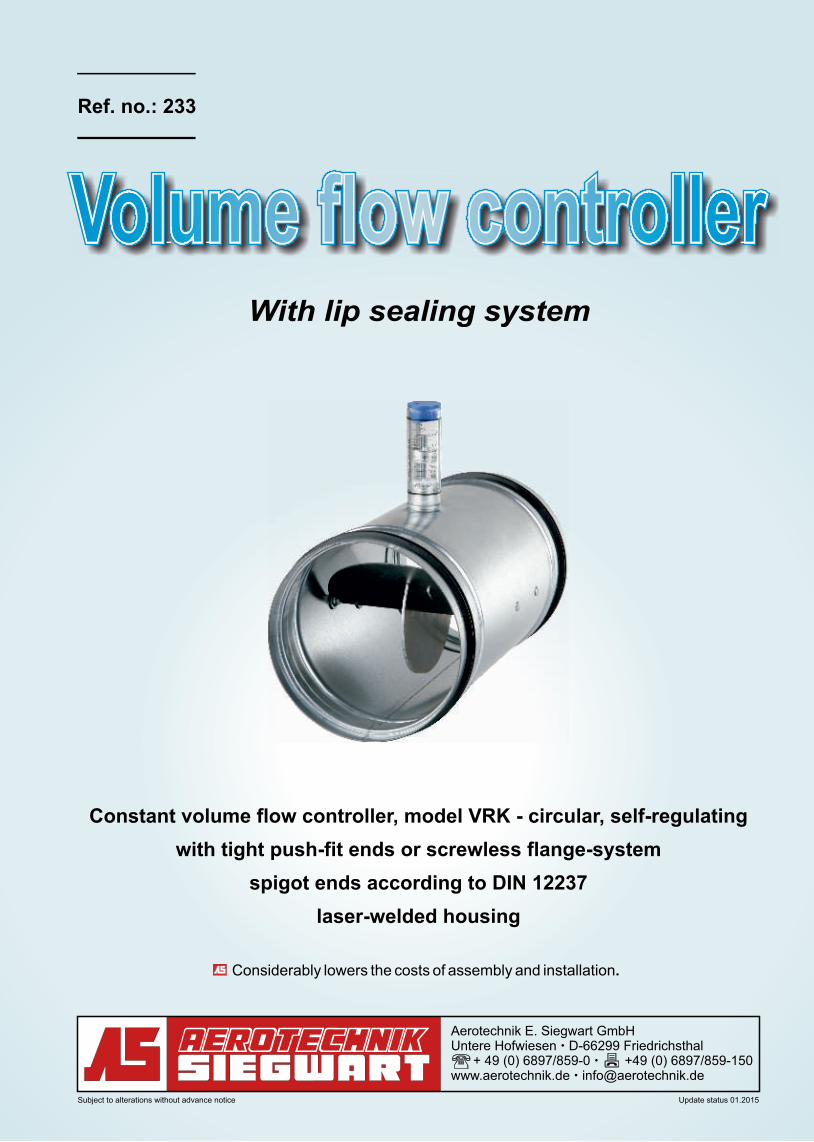
Constant volume flow controller, model VRK - circular, self-regulating
with tight push-fit ends or screwless flange-system
spigot ends according to DIN 12237
laser-welded housing
Considerably lowers the costs of assembly and installation.
With lip sealing system
Volume flow controllerVolume flow controller
Ref. no.: 233
- 2 -
Aerotechnik E. Siegwart GmbH Untere Hofwiesen – D-66299 Friedrichsthal + 49 (0) 6897/859-0 – +49 (0) 6897/859-150 www.aerotechnik.de – [email protected]
Application: The volume flow controllers VRK are used in complex piping systems for automatically controlling
the amount of air distribution. Their task is to maintain a predetermined desired value of the air
flow for the supply or exhaust air of a room sustainable and independent from fluctuating channel
air pressure. In a special version (see "temperature range"), the controllers can also be used for
certain functions within smoke extraction systems.
Function: In constant-volume controllers without auxiliary power, the flow control is achieved by an easy-
moving, asymmetrical angled control panel that ensures a sensitive response and control
behavior even for small amounts of air flow rates.
Response and
control accuracy: The controller operates from the minimum pressure difference, which is a function of the volume
flow (see diagram 1), up to the maximum pressure difference of 1000 Pa in a stable control range.
Over this entire pressure range, the flow rate deviation is ± 10% (less than 100 m³ / h ± 10 m³/h).
For smaller air speeds below 4 m/s and horizontal installation, the flow deviation can easily be
larger than indicated above. Unfavorable flow conditions, pollution or minor bracing during
installation can also cause larger deviations.
Temperature Range: The components of the controller are largely resistant to aging and temperature resistant from -30
°C to + 100 °C. On request, the controller is also available in a special version with a temperature
resistance up to 250 °C. In volume controllers with actuators the limiting operating temperatures
of the actuators apply, which can be different depending on the type and make.
Controller assembly: The control panel is mounted in a smooth and maintenance-free PTFE bushing. The support is
not guided through the pipe body shell, which means that no leaks or high-frequency whistling
sounds occur. A pneumatic piston damper prevents overshoot and oscillation of the control plate
and ensures an accurate response and control behavior.
Installation: The exact balancing of the control plate is ensured by a counterweight arranged vertically on the
control plate, which ensures an accurate control response in all orientations. The flow profile in
front of the flow controller should be cross-section-filling, since unfavorable flow conditions (such
as asymmetric flow, necking, deflection around sharp edges) can negatively affect the response
and control behavior.
Setting: The constant-volume flow controllers are shipped with either the volume flow required by the cus-
tomer or with a reference flow rate set at the factory. The volume flow can be changed at any time
by the customer and read on a scale by manual adjustment with an Allen wrench (2 mm).
Optionally, the air flow setpoint can be varied by an electric or pneumatic actuator.
Dimensions: In the selection of the controller and the dimensioning of the pipeline system it should be noted
that the flow rate should not be less than 2.7 m / s in the pipe system. The front and downstream
piping system to the controller should have the same diameter. As a reference value, a mean air
velocity in the pipe of about 4.5 m / s is recommended as central and orientation value.
Insulation: The flow controllers can be implemented with a sound and heat insulation in the thicknesses 25 or
50 mm with acoustic cladding.
Ref. no.: 233Constant volume flow controller
automatically regulating - circular
Subject to alterations without advance notice Update status 01.2015
- 3 -
Aerotechnik E. Siegwart GmbH Untere Hofwiesen – D-66299 Friedrichsthal + 49 (0) 6897/859-0 – +49 (0) 6897/859-150 www.aerotechnik.de – [email protected]
Installation note: According to DIN 1946 T2 an accessibility to the piping system and the volume flow controller for
operation and maintenance must be observed. For installation in vertical pipes an additional
protection against withdrawal is needed, e.g. by pressing a wart.
Pipe body: The body tubes are made of galvanized sheet steel or optionally of stainless steel. These are
laser butt welded without disturbing misalignment of the inner and outer shell surface. The plug
ends are dimensionally press calibrated according to DIN 12237 and are hereby dimensionally
stable and fit accurately.
Sealing systems of the connector:
Tightness: The connector with rubber lip is air-tight according to DIN EN 12237 Class D.
Replacement: If the lip rubber seal is damaged or lost due to any unforeseen circumstance, a new sealing ring is
easily slipped on
Removal: By the seal design, the components can be separated again.
View Mounting: There is no need for additional sealing means such as duct tape, hence the seal design with lip rub-
ber seal is particularly suitable for visual montages. Contemporary, attractive, architectonic style.
Hygiene: The smooth surface of the laser-welded housing prevents the accumulation of dirt and dust
particles.
Resistance: Ageing resistant rubber lip seal made of EPDM material, inert against weakly aggressive vapors
and chemicals.
ATEX: The constant-flow regulator can also be manufactured in explosion-proof design according to
ATEX. It can be used accordingly corresponding to the device category 2 in the gas-explosion
protection zones 1 or 2, and in the dust explosion protection zones 21 and 22. The controller is
characterized as follows: II 2 GD c IIB 80°
Packaging: For the construction site storage or applications with elevated pure-safety requirements, the
controllers can be supplied in a protective film for a small extra charge. Impurities in the interior of
the controller, which may adversely affect the control behavior, are here-by avoided.
Ref. no.: 233Constant volume flow controller
automatically regulating - circular
Subject to alterations without advance notice Update status 01.2015
- 4 -
Span ofthe jaw 2
Allen key
Adjustment device
(+) (-)
min.
max.
Movable
spring pin
B1
A1
l2l2
l3
l1
Siz
e
Ø 8
0 -
400
70
l2l2
l3
l1
Siz
e
Ø 8
0 -
250
l2l2
l3
l1
Siz
e
Ø 3
15 -
400
110
B2
A2
l2l2
l3
l1
Siz
e
Ø 8
0 -
400
Aerotechnik E. Siegwart GmbH Untere Hofwiesen – D-66299 Friedrichsthal + 49 (0) 6897/859-0 – +49 (0) 6897/859-150 www.aerotechnik.de – [email protected]
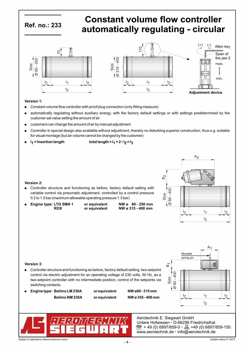
! Constant volume flow controller with proof plug connection (only fitting measure)
! automatically regulating without auxiliary energy, with the factory default settings or with settings predetermined by the
customer set value setting the amount of air
! customers can change the amount of air by manual adjustment
! Controller in special design also available without adjustment, thereby no disturbing superior construction, thus e.g. suitable
for visual montage (but air volume cannot be changed by the customer)
! l = Insertion length total length = l + 2 l = l*1 1 2 3
Version 1:
! Controller structure and functioning as before, factory default setting with
variable control via pneumatic adjustment, controlled by a control pressure
0.2 to 1.0 bar (maximum allowable operating pressure 1.3 bar)
! Engine type: LTG SMA 1 or equivalent NW ø 80 - 250 mm ROX or equivalent NW ø 315 - 400 mm
Version 2:
! Controller structure and functioning as before, factory default setting, two-setpoint
control via electric adjustment for an operating voltage of 230 volts, 50 Hz, as a
two-setpoint controller with no intermediate position, control of the setpoints via
switching contacts.
! Engine type: Belimo LM 230A or equivalent NW ø 80 - 315 mm
Belimo NM 230A or equivalent NW ø 355 - 400 mm
Version 3:
Ref. no.: 233Constant volume flow controller
automatically regulating - circular
Subject to alterations without advance notice Update status 01.2015
- 5 -
Aerotechnik E. Siegwart GmbH Untere Hofwiesen – D-66299 Friedrichsthal + 49 (0) 6897/859-0 – +49 (0) 6897/859-150 www.aerotechnik.de – [email protected]
! Controller structure and functioning analogous to version 3, but with an operating voltage of 24 volts
! Engine type: Belimo LM 24A or equivalent NW ø 80 - 315 mm
Belimo NM 24A or equivalent NW ø 355 - 400 mm
Version 5:
! Controller structure and functioning analogous to version 3, but variable control via electric adjustment for an operating
voltage of 24 volts, 50 Hz, with the control signal 2-10 VDC
! Engine type: Belimo LM 24A-MF or equivalent NW ø 80 - 315 mm
Belimo NM 24A-MF or equivalent NW ø 355 - 400 mm
Version 6:
Ref. no.: 233Constant volume flow controller
automatically regulating - circular
Subject to alterations without advance notice Update status 01.2015
- 6 -
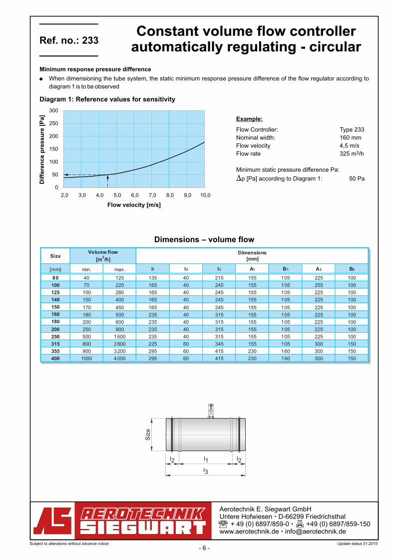
Size
[mm] min. max. l1 l2 l3 A1 B1 A2 B2
80 40 125 135 40 215 155 105 225 100
100 70 220 165 40 245 155 105 255 100
125 100 280 165 40 245 155 105 225 100
140 150 400 165 40 245 155 105 225 100
150 170 450 165 40 245 155 105 225 100
160 180 500 235 40 315 155 105 225 100
180 200 600 235 40 315 155 105 225 100
200 250 900 235 40 315 155 105 225 100
250 500 1600 235 40 315 155 105 225 100
315 800 2800 225 60 345 155 105 300 150
355 900 3200 295 60 415 230 160 300 150
400 1000 4000 295 60 415 230 160 300 150
Volume flow
[m3/h]
Dimensions[mm]
2,0 3,0 4,0 5,0 6,0 7,0 8,0 9,0 10,0
0
50
100
150
200
250
300
Flow velocity [m/s]
Dif
fere
nc
e p
res
su
re [
Pa
]
l2l2
l3
l1
Siz
e
Aerotechnik E. Siegwart GmbH Untere Hofwiesen – D-66299 Friedrichsthal + 49 (0) 6897/859-0 – +49 (0) 6897/859-150 www.aerotechnik.de – [email protected]
Example:
Flow Controller: Type 233
Nominal width: 160 mm
Flow velocity 4,5 m/s3Flow rate 325 m /h
Minimum static pressure difference Pa:
)p [Pa] according to Diagram 1: 50 Pa
Diagram 1: Reference values for sensitivity
Dimensions – volume flow
! When dimensioning the tube system, the static minimum response pressure difference of the flow regulator according to
diagram 1 is to be observed
Minimum response pressure difference
Ref. no.: 233Constant volume flow controller
automatically regulating - circular
Subject to alterations without advance notice Update status 01.2015
- 7 -
63
Hz
125
Hz
250
Hz
500
Hz
1000
Hz
2000
Hz
4000
Hz
8000
Hz
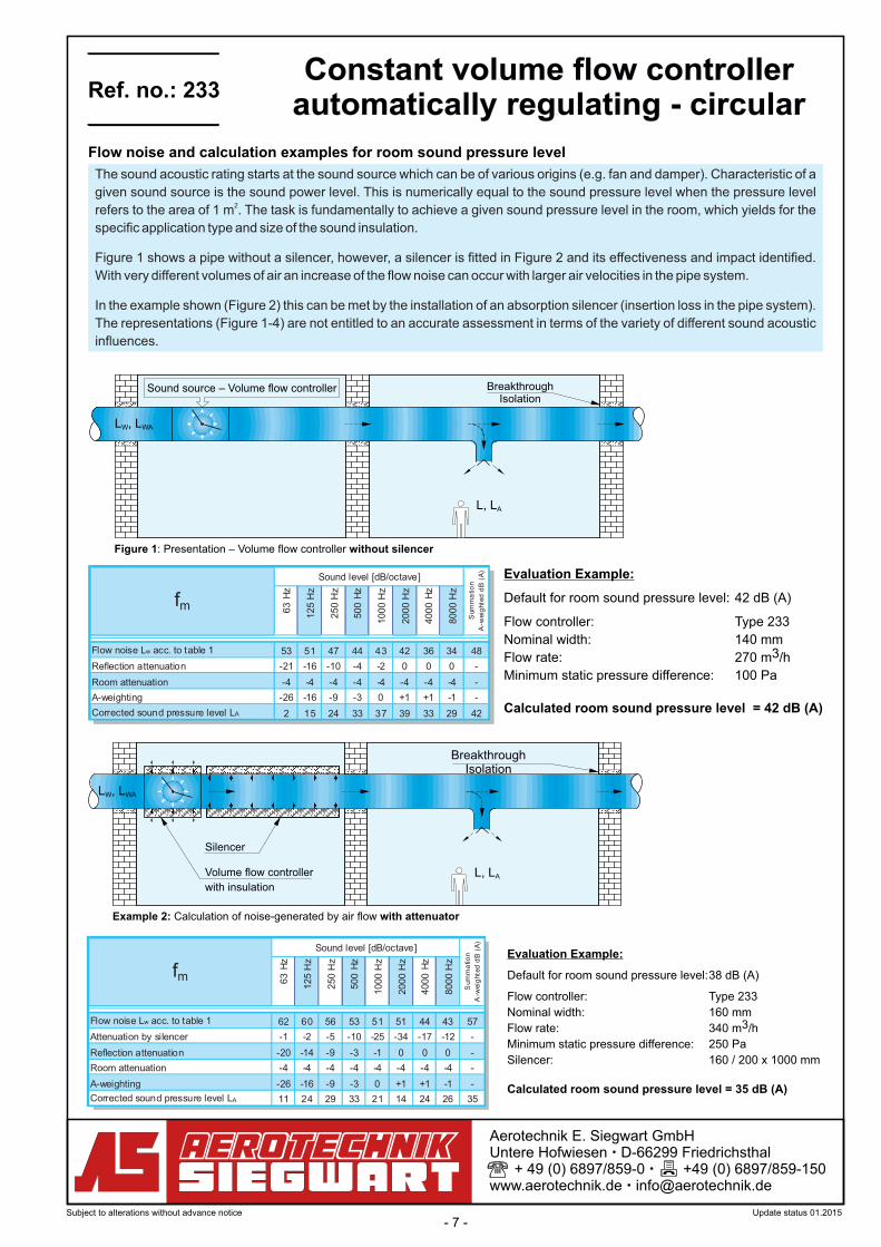
Flow noise Lw acc. to table 1 53 51 47 44 43 42 36 34 48
Reflection attenuation -21 -16 -10 -4 -2 0 0 0 -
Room attenuation -4 -4 -4 -4 -4 -4 -4 -4 -
A-weighting -26 -16 -9 -3 0 +1 +1 -1 -
Corrected sound pressure level LA 2 15 24 33 37 39 33 29 42
fm
Sum
ma
tio
n
A-w
eig
hte
dd
B(A
)
Sound level [dB/octave]
63
Hz
125
Hz
250
Hz
500
Hz
1000
Hz
2000
Hz
4000
Hz
8000
Hz
Flow noise Lw acc. to table 1 62 60 56 53 51 51 44 43 57
Attenuation by silencer -1 -2 -5 -10 -25 -34 -17 -12 -
Reflection attenuation -20 -14 -9 -3 -1 0 0 0 -
Room attenuation -4 -4 -4 -4 -4 -4 -4 -4 -
A-weighting -26 -16 -9 -3 0 +1 +1 -1 -
Corrected sound pressure level LA 11 24 29 33 21 14 24 26 35
fm
Sum
ma
tio
n
A-w
eig
hte
dd
B(A
)
Sound level [dB/octave]
L , LW WA
Sound source – Volume flow controller BreakthroughIsolation
L, LA
Figure 1: Presentation – Volume flow controller without silencer
Aerotechnik E. Siegwart GmbH Untere Hofwiesen – D-66299 Friedrichsthal + 49 (0) 6897/859-0 – +49 (0) 6897/859-150 www.aerotechnik.de – [email protected]
L , LW WA
Volume flow controller
with insulation
BreakthroughIsolation
L, LA
Example 2: Calculation of noise-generated by air flow with attenuator
Silencer
Evaluation Example:
Default for room sound pressure level: 42 dB (A)
Flow controller: Type 233
Nominal width: 140 mm3Flow rate: 270 m /h
Minimum static pressure difference: 100 Pa
Calculated room sound pressure level = 42 dB (A)
Evaluation Example:
Default for room sound pressure level: 38 dB (A)
Flow controller: Type 233
Nominal width: 160 mm3Flow rate: 340 m /h
Minimum static pressure difference: 250 Pa
Silencer: 160 / 200 x 1000 mm
Calculated room sound pressure level = 35 dB (A)
Flow noise and calculation examples for room sound pressure level
The sound acoustic rating starts at the sound source which can be of various origins (e.g. fan and damper). Characteristic of a
given sound source is the sound power level. This is numerically equal to the sound pressure level when the pressure level 2refers to the area of 1 m . The task is fundamentally to achieve a given sound pressure level in the room, which yields for the
specific application type and size of the sound insulation.
Figure 1 shows a pipe without a silencer, however, a silencer is fitted in Figure 2 and its effectiveness and impact identified.
With very different volumes of air an increase of the flow noise can occur with larger air velocities in the pipe system.
In the example shown (Figure 2) this can be met by the installation of an absorption silencer (insertion loss in the pipe system).
The representations (Figure 1-4) are not entitled to an accurate assessment in terms of the variety of different sound acoustic
influences.
Ref. no.: 233Constant volume flow controller
automatically regulating - circular
Subject to alterations without advance notice Update status 01.2015
- 8 -
63
Hz
12
5H
z
25
0H
z
50
0H
z
10
00
Hz
20
00
Hz
40
00
Hz
80
00
Hz
63
Hz
12
5H
z
25
0H
z
50
0H
z
10
00
Hz
20
00
Hz
40
00
Hz
80
00
Hz
63
Hz
12
5H
z
25
0H
z
50
0H
z
10
00
Hz
20
00
Hz
40
00
Hz
80
00
Hz
40 37 37 35 33 33 33 28 27 38 39 42 43 44 44 46 41 41 50 46 49 49 50 51 53 48 48 57
82 49 47 44 41 39 39 33 32 45 51 51 50 49 48 49 44 44 54 58 58 56 55 55 56 51 51 61
125 52 51 48 45 44 44 38 37 49 61 60 57 54 53 53 47 46 58 68 66 63 61 59 59 53 52 65
70 40 39 38 36 35 36 30 29 41 43 45 46 46 47 49 44 43 53 49 52 52 53 54 55 50 50 60
135 50 48 45 42 41 40 34 33 46 59 57 54 51 50 49 43 42 55 60 60 58 57 57 58 53 52 63
200 54 52 49 47 45 45 39 38 51 63 61 58 55 54 54 48 47 59 70 68 65 62 61 60 54 53 66
100 41 40 38 36 35 36 30 29 41 45 47 47 48 48 49 44 43 54 52 54 54 54 55 56 50 49 60
190 51 49 46 42 41 40 34 32 46 55 54 53 51 51 51 46 45 56 61 61 59 58 57 58 52 52 63
280 54 53 50 47 45 45 39 37 50 63 61 58 55 54 53 47 46 59 64 64 62 61 61 62 57 56 67
150 43 42 40 38 37 37 31 30 42 47 49 49 49 50 51 46 45 55 53 56 56 56 56 58 52 51 62
270 53 51 47 44 43 42 36 34 48 61 59 56 53 51 51 44 43 57 63 63 61 60 59 60 54 54 65
400 56 55 52 49 47 47 41 39 52 65 63 60 57 56 55 49 48 61 72 70 67 64 62 62 56 55 68
150 43 42 40 38 37 37 31 30 42 47 49 49 49 50 51 45 44 55 54 56 56 56 56 57 52 51 62
270 52 50 46 43 41 41 34 33 47 56 56 54 52 52 52 46 46 57 63 62 60 59 58 59 53 52 64
400 56 54 50 47 46 45 39 38 51 64 62 59 56 54 54 48 46 60 65 65 64 62 62 63 57 57 68
180 44 43 41 39 38 38 32 31 43 48 50 50 50 50 51 46 45 56 55 57 57 57 57 58 53 51 63
340 53 51 48 44 43 42 36 34 48 62 60 56 53 51 51 44 43 57 64 64 62 60 60 60 55 54 65
500 57 55 52 49 47 47 40 39 52 66 64 61 58 56 55 49 48 61 72 70 67 64 62 62 56 54 68
250 45 43 41 39 38 37 31 30 43 51 52 52 51 51 51 45 44 56 57 59 58 58 57 58 52 50 63
575 55 53 50 46 44 44 37 36 50 64 62 58 55 53 53 46 45 59 66 66 64 62 62 62 56 56 67
900 - - - - - - - - - 68 66 63 60 58 58 52 50 64 75 73 70 67 65 65 58 57 70
500 48 47 45 43 41 41 35 34 47 54 56 55 55 54 55 49 48 60 61 62 62 61 61 62 56 54 66
1000 57 55 52 49 47 46 39 38 52 66 64 61 57 55 55 48 47 61 69 68 67 65 64 64 59 58 69
1500 - - - - - - - - - 70 68 65 62 60 60 53 52 65 77 75 72 68 67 66 60 58 72
800 48 46 44 41 39 39 32 31 44 55 56 55 54 53 53 46 44 58 62 63 62 61 60 59 53 51 65
1400 57 55 52 48 46 45 39 37 51 66 64 60 57 55 54 47 46 60 70 69 67 65 64 64 58 57 69
2200 - - - - - - - - - 71 69 65 62 60 59 53 51 65 77 75 72 69 67 66 60 58 72
900 50 48 46 43 42 41 35 33 47 57 58 57 56 55 55 49 47 60 64 65 64 63 62 62 55 53 672000 59 57 53 50 48 47 40 39 53 68 66 62 59 57 56 49 47 62 72 71 69 67 66 66 60 59 71
3200 - - - - - - - - - 73 71 67 64 62 61 55 54 68 79 77 74 71 69 68 62 60 741000 50 48 45 42 41 40 33 31 46 58 59 57 56 55 54 47 45 59 65 65 64 62 61 61 54 51 662200 58 56 52 49 47 46 39 37 52 67 65 61 57 55 54 48 46 61 72 71 68 66 65 65 59 57 70
3800 - - - - - - - - - 73 71 67 64 62 61 55 53 67 79 77 74 70 68 68 61 60 74
355
400
Sum
matio
n
Lw
sum
A-w
eig
hte
ddB
(A)
Siz
e[m
m]
Vo
lum
efl
ow
[m3/h]
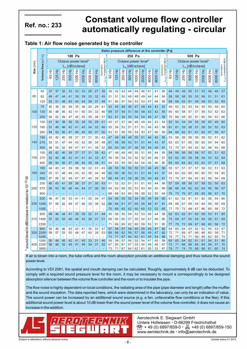
Static pressure difference at the controller [Pa]
100 Pa 500 Pa
Lw [dB/octave] Lw [dB/octave] Lw [dB/octave]
Octave power level*
Sum
ma
tion
Lw
sum
A-w
eig
hte
dd
B(A
)
Octave power level* Octave power level*
250 Pa
125
140
80
100
Sum
mation
Lw
sum
A-w
eig
hte
ddB
(A)
200
150
315
250
160
Aerotechnik E. Siegwart GmbH Untere Hofwiesen – D-66299 Friedrichsthal + 49 (0) 6897/859-0 – +49 (0) 6897/859-150 www.aerotechnik.de – [email protected]
If air is blown into a room, the tube orifice and the room absorption provide an additional damping and thus reduce the sound
power level.
According to VDI 2081, the spatial and mouth damping can be calculated. Roughly, approximately 8 dB can be deducted. To
comply with a required sound pressure level for the room, it may be necessary to mount a correspondingly to be designed
absorption silencer between the volume flow controller and the room or to insulate the pipe.
The flow noise is highly dependent on local conditions, the radiating area of the pipe (pipe diameter and length) after the muffler
and the sound insulation. The data reported here, which were determined in the laboratory, can only be an indication of value.
The sound power can be increased by an additional sound source (e.g. a fan, unfavorable flow conditions or the like). If this
additional sound power level is about 10 dB lower than the sound power level of the volume flow controller, it does not cause an
increase in the addition.
Table 1: Air flow noise generated by the controller
-12
* so
und le
vel i
n d
B/o
ctave
in rela
tion to
10
WRef. no.: 233
Constant volume flow controllerautomatically regulating - circular
Subject to alterations without advance notice Update status 01.2015
- 9 -
63
Hz
125
Hz
250
Hz
500
Hz
1000
Hz
2000
Hz
4000
Hz
8000
Hz
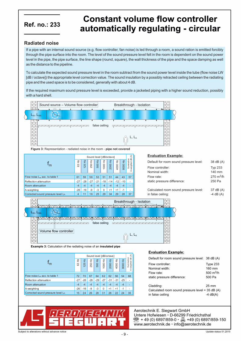
Flow noise Lw acc. to table 1 72 70 67 64 62 62 56 54 68
Reflection attenuation -27 -26 -28 -29 -27 -31 -31 -25 -
Room attenuation -4 -4 -4 -4 -4 -4 -4 -4 -
A-weighting -26 -16 -9 -3 0 +1 +1 -1 -
Corrected sound pressure level LA 15 24 26 28 31 28 22 24 35
fm
Sum
ma
tio
n
A-w
eig
hte
dd
B(A
)
Sound level [dB/octave]
63
Hz
125
Hz
250
Hz
500
Hz
1000
Hz
2000
Hz
4000
Hz
8000
Hz
Flow noise Lw acc. to table 1 61 59 56 53 51 51 44 43 57
Reflection attenuation -27 -28 -27 -21 -18 -14 -12 -10 -
Room attenuation -4 -4 -4 -4 -4 -4 -4 -4 -
A-weighting -26 -16 -9 -3 0 +1 +1 -1 -
Corrected sound pressure level LA 4 11 16 25 29 34 29 28 37
fm
Su
mm
ati
on
A-w
eig
hte
dd
B(A
)
Sound level [dB/octave]
L , LW WA
Sound source – Volume flow controller Breakthrough - Isolation
L, LA
false ceiling
Figure 3: Representation - radiated noise in the room - pipe not covered
Evaluation Example:
Default for room sound pressure level: 38 dB (A)
Flow controller: Typ 233
Nominal width: 140 mm3Flow rate: 270 m /h
static pressure difference: 250 Pa
Calculated room sound pressure level: 37 dB (A)
in false ceiling: -4 dB (A)
Example 3: Calculation of the radiating noise of an insulated pipe
L , LW WA
Breakthrough - Isolation
L, LA
false ceiling
Volume flow controller
Aerotechnik E. Siegwart GmbH Untere Hofwiesen – D-66299 Friedrichsthal + 49 (0) 6897/859-0 – +49 (0) 6897/859-150 www.aerotechnik.de – [email protected]
If a pipe with an internal sound source (e.g. flow controller, fan noise) is led through a room, a sound ration is emitted forcibly
through the pipe surface into the room. The level of the sound pressure level felt in the room is dependent on the sound power
level in the pipe, the pipe surface, the line shape (round, square), the wall thickness of the pipe and the space damping as well
as the distance to the pipeline.
To calculate the expected sound pressure level in the room subtract from the sound power level inside the tube (flow noise LW
[dB / octave]) the appropriate level correction value. The sound insulation by a possibly retracted ceiling between the radiating
pipe and the used space is to be considered, generally with about 4 dB.
If the required maximum sound pressure level is exceeded, provide a jacketed piping with a higher sound reduction, possibly
with a hard shell.
Radiated noise
Evaluation Example:
Default for room sound pressure level: 38 dB (A)
Flow controller: Type 233
Nominal width: 160 mm3Flow rate: 500 m /h
static pressure difference: 500 Pa
Cladding: 25 mm
Calculated room sound pressure level = 35 dB (A)
in false ceiling -4 dB(A)
Ref. no.: 233Constant volume flow controller
automatically regulating - circular
Subject to alterations without advance notice Update status 01.2015

- 10 -
63
Hz
12
5H
z
25
0H
z
50
0H
z
10
00
Hz
20
00
Hz
40
00
Hz
80
00
Hz
63
Hz
12
5H
z
25
0H
z
50
0H
z
10
00
Hz
20
00
Hz
40
00
Hz
80
00
Hz
63
Hz
12
5H
z
25
0H
z
50
0H
z
10
00
Hz
20
00
Hz
40
00
Hz
80
00
Hz
80 36 33 32 23 17 12 11 11 39 35 39 35 32 33 34 29 42 37 45 46 47 54 56 47
100 34 32 30 22 16 12 11 10 38 35 38 34 31 33 34 28 41 38 46 45 47 54 57 47
125 29 29 31 24 21 19 15 11 35 33 37 36 32 33 36 27 35 36 42 48 51 60 58 45
140 27 28 27 21 18 14 12 10 29 29 32 32 32 33 33 26 31 30 37 42 45 52 54 44
150 25 25 23 19 14 12 11 9 28 27 30 30 29 32 32 25 30 29 36 41 44 51 54 44
160 23 23 20 18 11 10 9 8 27 26 28 29 27 31 31 25 29 28 35 40 44 51 54 44
180 22 21 18 17 12 10 9 8 25 22 25 27 27 30 30 24 27 25 32 38 43 51 53 43
200 22 19 16 16 15 11 9 8 23 18 23 26 29 29 29 24 26 22 29 37 42 51 53 43
250 19 16 13 12 12 10 9 8 23 18 20 24 26 30 28 24 25 20 26 35 41 50 52 42
315 18 14 12 13 11 11 8 8 22 17 19 23 27 29 28 24 26 18 26 38 42 51 53 45355 17 12 11 11 10 10 7 7 20 15 18 22 26 28 27 23 23 17 24 35 40 49 51 42400 17 11 10 10 10 9 7 6 19 14 17 22 25 28 27 23 20 16 23 33 39 48 50 40
Siz
e[m
m]
Correction value [dB/octave] Correction va lue [dB/octave] Correction value [dB/octave]
WallFolded spiral pipeaccording to DIN 24145
6 m
Insulation with1 mmsheet steel and25 mm mineral wool
Wall
6 m
Wall
Insulation with1 mmsheet steel and50 mm mineral wool
6 m
Aerotechnik E. Siegwart GmbH Untere Hofwiesen – D-66299 Friedrichsthal + 49 (0) 6897/859-0 – +49 (0) 6897/859-150 www.aerotechnik.de – [email protected]
Table 2: level correction values to calculate the radiated noise of a 6 m long pipe with built-in flow-regulator
Key to symbols
(general sound acoustically relevant indices)
L [dB] sound power levelW
L [dB (A)] sound power level, A-weightedWA
L [dB] sound pressure level
L [dB (A)] Sound pressure level, A-weightedA
Ref. no.: 233Constant volume flow controller
automatically regulating - circular
Subject to alterations without advance notice Update status 01.2015