Alfa Laval Brew 80 Separationsmodul 10 – 50 hl/h · Alfa Laval Brew 80 Disc stack separation...
4
14 Alfa Laval Brew 80 Separationsmodul 10 – 50 hl/h Separation Anwendungsbereich » Vorklärung » Jungbierklärung » Hä » B Funktionsprinzip » Zufuhr von oben in die rotierende Zentrifugentrommel » Beschleunigung in einem Verteiler » Einleitung in ein Tellerpaket » Kä T a » Das Produkt klärt sich auf dem Weg in Richtung Mitte der Trommel, wo es unter Druck mittels einer eingebauten Schälscheibe hinausgepumpt wird » Der schwerere Feststoffabschnitt wird am Rand der Trommel in Intervallen abgelassen Technische Daten Durchsatz: 15 – 50 hl / h Separator Motorgröße: 11 kW Anschluss: DN-32 Aa S » Automatische Schussauslösung über Trübungsmessgerät im Auslauf » Einlaufregelventil » Minor und Major Service Kit » 5 Tage Servicetechniker für die Inbetriebnahme inkl. Reisezeit und -kosten in Deutschland
Transcript of Alfa Laval Brew 80 Separationsmodul 10 – 50 hl/h · Alfa Laval Brew 80 Disc stack separation...
14
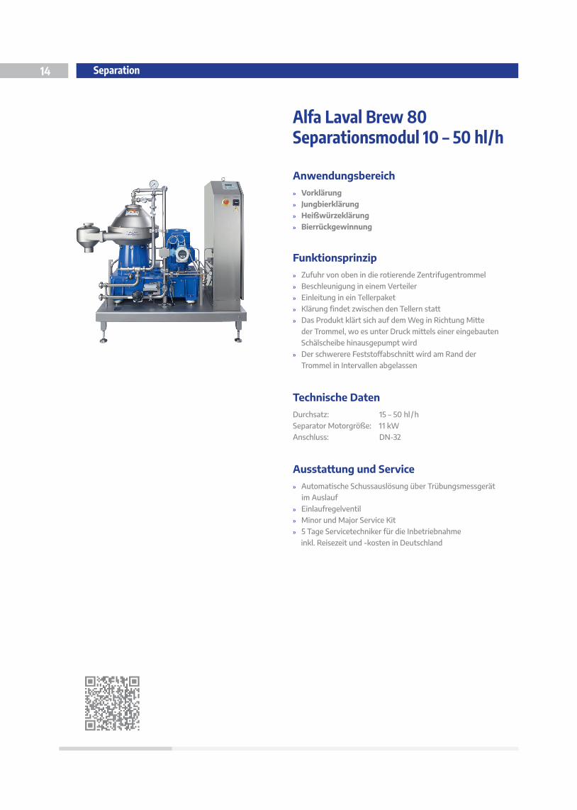
Alfa Laval Brew 80Separationsmodul 10 – 50 hl/h
Separation
Anwendungsbereich
» Vorklärung
» Jungbierklärung
» Heißwürzeklärung » Bierrückgewinnung
Funktionsprinzip
» Zufuhr von oben in die rotierende Zentrifugentrommel
» Beschleunigung in einem Verteiler
» Einleitung in ein Tellerpaket
» Klärung findet zwischen den Tellern statt » Das Produkt klärt sich auf dem Weg in Richtung Mitte
der Trommel, wo es unter Druck mittels einer eingebauten
Schälscheibe hinausgepumpt wird
» Der schwerere Feststoffabschnitt wird am Rand der
Trommel in Intervallen abgelassen
Technische Daten
Durchsatz: 15 – 50 hl /h
Separator Motorgröße: 11 kW
Anschluss: DN-32
Ausstattung und Service » Automatische Schussauslösung über Trübungsmessgerät
im Auslauf
» Einlaufregelventil
» Minor und Major Service Kit
» 5 Tage Servicetechniker für die Inbetriebnahme
inkl. Reisezeit und -kosten in Deutschland
Alfa Laval Brew 80Disc stack separation system for brewery applications
Introduction
The use of separators in different brewery applications goes
back to the beginning of the 1900’s. Based on the long-term
cooperation with the brewery industry, Alfa Laval separators
are specially designed for the requirements and demands of
this industry.
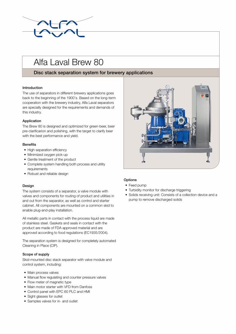
Application
The Brew 80 is designed and optimized for green-beer, beer
pre-clarificarion and polishing, with the target to clarify beer
with the best performance and yield.
Benefits
• High separation efficiency
• Minimized oxygen pick-up
• Gentle treatment of the product
• Complete system handling both process and utility
requirements
• Robust and reliable design
Design
The system consists of a separator, a valve module with
valves and components for routing of product and utilities in
and out from the separator, as well as control and starter
cabinet. All components are mounted on a common skid to
enable plug-and-play installation.
All metallic parts in contact with the process liquid are made
of stainless steel. Gaskets and seals in contact with the
product are made of FDA approved material and are
approved according to food regulations (EC1935/2004).
The separation system is designed for completely automated
Cleaning in Place (CIP).
Scope of supply
Skid-mounted disc stack separator with valve module and
control system, including:
• Main process valves
• Manual flow regulating and counter pressure valves
• Flow meter of magnetic type
• Main motor starter with VFD from Danfoss
• Control panel with EPC 60 PLC and HMI
• Sight glasses for outlet
• Samples valves for in- and outlet
Options
• Feed pump
• Turbidity monitor for discharge triggering
• Solids receiving unit: Consists of a collection device and a
pump to remove discharged solids
Working principle
The product enters and leaves the separator via the valve
module. The flow rate and the counter pressure in the outlet
of the separator are controlled by the process liquid module.
Discharge of solids from the separator bowl is triggered by a
timer or by a turbidity meter, placed in the outlet of the
system. The discharged solids are pumped away by the
optional solids receiving unit.
The valve module also controls the utility liquids for the
separator’s discharge system and for flushing and CIP.
1
2
QT QT
3
12
4
5
8
6
9
7
10
11
13
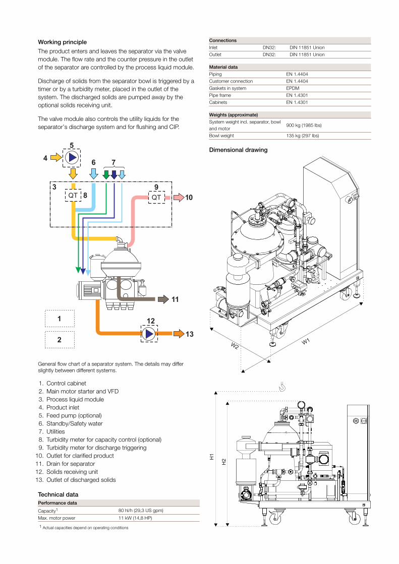
General flow chart of a separator system. The details may differ
slightly between different systems.
1. Control cabinet
2. Main motor starter and VFD
3. Process liquid module
4. Product inlet
5. Feed pump (optional)
6. Standby/Safety water
7. Utilities
8. Turbidity meter for capacity control (optional)
9. Turbidity meter for discharge triggering
10. Outlet for clarified product
11. Drain for separator
12. Solids receiving unit
13. Outlet of discharged solids
Technical data
Performance data
Capacity1 80 hl/h (29,3 US gpm)
Max. motor power 11 kW (14,8 HP)
1 Actual capacities depend on operating conditions
Connections
Inlet DN32: DIN 11851 Union
Outlet DN32: DIN 11851 Union
Material data
Piping EN 1.4404
Customer connection EN 1.4404
Gaskets in system EPDM
Pipe frame EN 1.4301
Cabinets EN 1.4301
Weights (approximate)
System weight incl. separator, bowl
and motor900 kg (1985 lbs)
Bowl weight 135 kg (297 lbs)
Dimensional drawing
W2
W1
H2H
1
Dimensions
H1 Min. 2150 mm (7 ft 5/8 inch)
H2 1695 mm (5 ft 6 3/4 inch)
W1 1825 mm (5 ft 11 7/8 inch)
W2 890 mm (2 ft 11 1/6 inch)
This document and its contents is owned by Alfa Laval Corporate AB and protected by laws governing intellectual property and thereto related rights. It is the responsibility of the user of thisdocument to comply with all applicable intellectual property laws. Without limiting any rights related to this document, no part of this document may be copied, reproduced or transmitted in anyform or by any means (electronic, mechanical, photocopying, recording, or otherwise), or for any purpose, without the expressed permission or authorized by Alfa Laval Corporate AB. Alfa LavalCorporate AB will enforce its rights related to this document to the fullest extent of the law, including the seeking of criminal prosecution.
200000282-1-EN-GB © Alfa Laval Corporate AB
How to contact Alfa Laval
Up-to-date Alfa Laval contact
details for all countries are
always available on our website
at www.alfalaval.com


![· Nachkommen von Didier Laval (53389) [1543-?] Familienbuch Erstellt mit DYNAS-TREE 0340.C09 Seite 1 Familienbuch Nachkommen von Didier LAVAL [1543 - ? ] Ident – Nr.](https://static.fdokument.com/doc/165x107/5f640be5026fd603de5813c5/nachkommen-von-didier-laval-53389-1543-familienbuch-erstellt-mit-dynas-tree.jpg)