Katalog SMS Servoantriebe 441712 - REM-Technik...ED401/ED402/ED403; ED503/ED505; ED704/ED706;...
34
SMS Servomotoren ED SMS ED Servo Motors Moteurs brushless SMS ED Moteurs brushless Gamme dynamique 6 modèles dotés de respectivement deux ou trois longueurs ED2 - ED8 Couple MN: ventilation à main: 0,44 - 45,1 Nm ventilation forcée: 2,45 - 67,2 Nm Couple d’immobilisation M0: ventilation à main: 0,48 - 58,0 Nm ventilation forcée: 3,19 - 86,4 Nm Frein à ressort intégré en option Frein d’arrêt sans jeu en option Ventilation à main Ventilation forcée en option Codeur absolue inductif / optique en standard Résolveur en option Servo Motors Dynamic Series 6 sizes each with 2 or 3 core stack lengths ED2 - ED8 Torque MN: self-ventilated: 0,44 - 45,1 Nm forced cooled: 2,45 - 67,2 Nm Stall torque M0: self-ventilated: 0,48 - 58,0 Nm forced cooled: 3,19 - 86,4 Nm Low backlash safety spring applied brake as an option Play-free holding brake as an option Self-ventilation Forced-air cooling as an option Standard absolute value encoders inductive / optical Resolvers as an option Servomotoren Dynamik-Baureihe 6 Baugrößen mit jeweils 2 - 3 Paketlängen ED2 - ED8 Drehmoment MN: unbelüftet: 0,44 - 45,1 Nm fremdbelüftet: 2,45 - 67,2 Nm Stillstandsdrehmoment M0: unbelüftet: 0,48 - 58,0 Nm fremdbelüftet: 3,19 - 86,4 Nm optional spielarme Sicherheits- Federdruckbremse optional spielfreie Haltebremse Eigenlüftung optional Fremdbelüftung Standard Absolutwertgeber induktiv / optisch optional Resolver SMS ED www.stoeber.de
Transcript of Katalog SMS Servoantriebe 441712 - REM-Technik...ED401/ED402/ED403; ED503/ED505; ED704/ED706;...

SMS Servomotoren ED
SMS ED Servo Motors Moteurs brushless SMS ED
Moteurs brushless
Gamme dynamique
6 modèles dotés de respectivementdeux ou trois longueurs ED2 - ED8Couple MN:ventilation à main: 0,44 - 45,1 Nmventilation forcée: 2,45 - 67,2 NmCouple d’immobilisation M0:ventilation à main: 0,48 - 58,0 Nmventilation forcée: 3,19 - 86,4 NmFrein à ressort intégré en optionFrein d’arrêt sans jeu en optionVentilation à mainVentilation forcée en optionCodeur absolue inductif / optique en standardRésolveur en option
Servo Motors
Dynamic Series
6 sizes each with 2 or 3 core stacklengths ED2 - ED8Torque MN:self-ventilated: 0,44 - 45,1 Nmforced cooled: 2,45 - 67,2 NmStall torque M0:self-ventilated: 0,48 - 58,0 Nmforced cooled: 3,19 - 86,4 NmLow backlash safety spring appliedbrake as an optionPlay-free holding brake as an optionSelf-ventilationForced-air cooling as an optionStandard absolute value encoders inductive / opticalResolvers as an option
Servomotoren
Dynamik-Baureihe
6 Baugrößen mit jeweils 2 - 3 Paketlängen ED2 - ED8Drehmoment MN:unbelüftet: 0,44 - 45,1 Nmfremdbelüftet: 2,45 - 67,2 NmStillstandsdrehmoment M0:unbelüftet: 0,48 - 58,0 Nmfremdbelüftet: 3,19 - 86,4 Nmoptional spielarme Sicherheits-Federdruckbremseoptional spielfreie HaltebremseEigenlüftung optional FremdbelüftungStandard Absolutwertgeber induktiv / optischoptional Resolver
SMS ED
www.stoeber.de
�
�
�
�
�
�
�
�
�
�
�
�
�
�
�
�
�
�
�
�
�
�
�
�
�
�
�
SMS Servomotoren EK
SMS EK Servo Motors Moteurs brushless SMS EK
Moteurs brushless
Gamme compact
3 modèles dotés de respectivementune ou deux longueurs EK5 - EK8Couple MN:ventilation à main: 2,6 - 21,6 Nmventilation forcée: 3,75 - 30,8 NmCouple d’immobilisation M0:ventilation à main: 3,36 - 25,2 Nmventilation forcée: 4,33 - 35,0 NmFrein d’arrêt sans jeu en optionVentilation à mainVentilation forcée en optionCodeur absolue inductif / optique en standardRésolveur en option
Servo Motors
Compact Series
3 sizes each with 1 or 2 core stacklengths EK5 - EK8Torque MN:self-cooled: 2,6 - 21,6 Nmforced-cooled: 3,75 - 30,8 NmStall torque M0:self-cooled: 3,36 - 25,2 Nmforced-cooled: 4,33 - 35,0 NmPlay-free holding brake as an optionSelf-ventilationForced-air cooling as an optionStandard absolute value encoders inductive / opticalResolvers as an option
Servomotoren
Kompakt-Baureihe
3 Baugrößen mit jeweils 1 - 2 Paketlängen EK5 - EK8Drehmoment MN:eigenbelüftet: 2,6 - 21,6 Nmfremdbelüftet 3,75 - 30,8 NmStillstandsdrehmoment M0:eigenbelüftet: 3,36 - 25,2 Nmfremdbelüftet: 4,33 - 35,0 Nmoptional spielfreie HaltebremseEigenlüftungoptional FremdbelüftungStandard Absolutwertgeber induktiv / optischoptional Resolver
www.stoeber.de
SMS EK
�
�
�
�
�
�
�
�
�
�
�
�
�
�
�
�
�
�
�
�
�
�
�
�
Moteurs brushless ED + EK
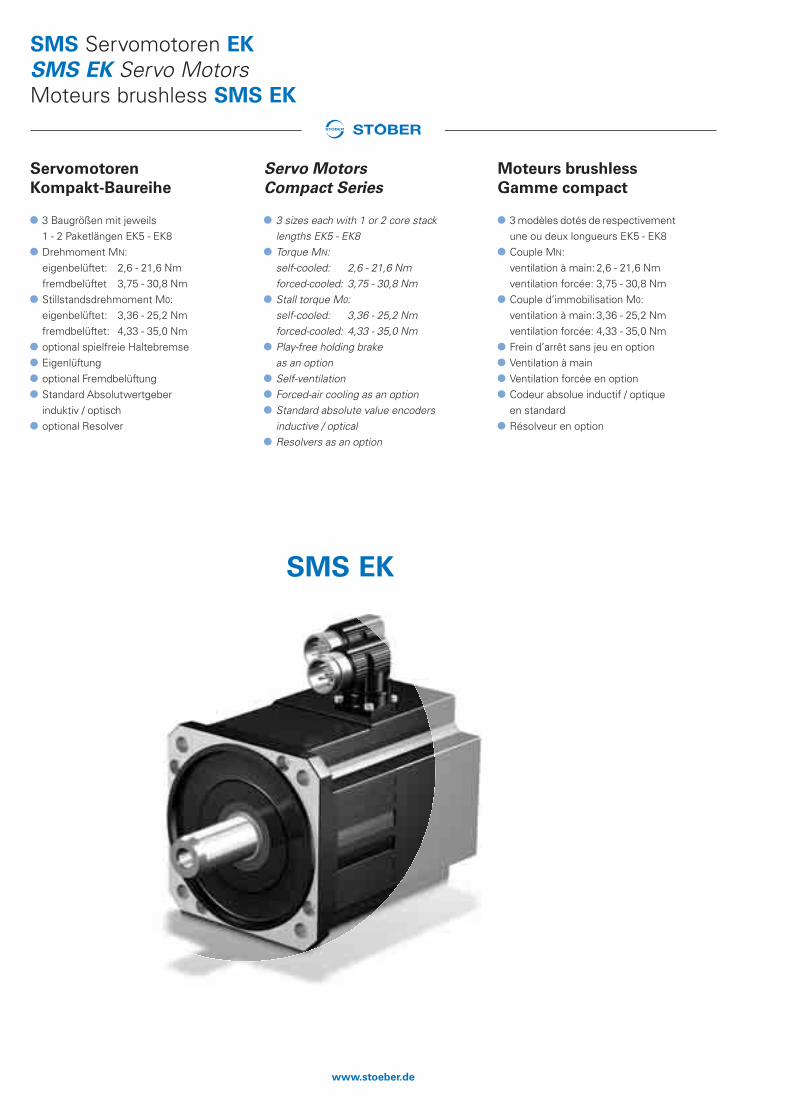
Sommaire MPrescriptions M2Exécution M3Désignation des types M7Formules M8Moteurs brushless ED Caractéristiques techniques M10Moteurs brushless EK Caractéristiques techniques M11Courbes caractéristiques M12Frein M17Codeur M20Ventilation forcée M21Connexion électrique - Bloc de puissance MDS/SDS 5000 M22Connexion électrique - Codeur MDS/SDS 5000 M23Croquis cotés:Moteurs brushless ED - connecteur multibroches M25Moteurs brushless ED - boîte à bornes M27Moteurs brushless ED - ventilation forcée M28Moteurs brushless EK - connecteur multibroches M29Moteurs brushless EK - boîte à bornes M30Moteurs brushless EK - ventilation forcée M31
Servo Motors ED + EK
Contents MStandards M2Design M3Type designation M7Formulas M8Servo Motors ED Technical data M10Servo Motors EK Technical data M11Characteristics M12Brake M17Encoder M20Forced-air cooling M21Electrical connection - power section MDS/SDS 5000 M22Electrical connection - Encoder MDS/SDS 5000 M23Dimensioned drawings:Servo Motors ED - connector M25Servo Motors ED - terminal box M27Servo Motors ED - forced cooled M28Servo Motors EK - connector M29Servo Motors EK - terminal box M30Servo Motors EK - forced cooled M31
Servomotoren ED + EK
Inhaltsübersicht MVorschriften M2Ausprägungen M3Typenbezeichnung M7Formelzeichen M8Servomotoren ED Technische Daten M10Servomotoren EK Technische Daten M11Kennlinien M12Bremse M17Encoder M20Fremdbelüftung M21Elektrischer Anschluss - Leistungsteil MDS/SDS 5000 M22Elektrischer Anschluss - Encoder MDS/SDS 5000 M23Maßbilder:Servomotoren ED - Steckverbinder M25Servomotoren ED - Klemmenkasten M27Servomotoren ED - fremdbelüftet M28Servomotoren EK - Steckverbinder M29Servomotoren EK - Klemmenkasten M30Servomotoren EK - fremdbelüftet M31
ID 441712.04 - 12.09 M1www.stoeber.de
MM

Moteurs brushless ED + EKPrescriptions
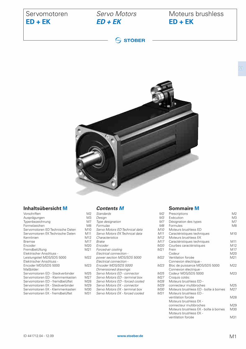
Les moteurs brushless ED et EK sont des mo-teurs de construction compacte, à aimant per-manent, sans balais, et de commutatin électro-nique hautement dynamiques et de conceptionmodulaire dans lesquels les composants destator et de rotor, qui ont une forme optimale dupoint de vue énergétique, garantissent à la foisune ondulation de couple extrêmement réduiteet une grande puissance volumique.Les moteurs brushless ED et EK peuvent êtreconnectés à des servoconvertisseurs pour destensions de circuit intermédiaire de 540 V. La ré-pétition a lieu par I’intermédiaire d’un codeurabsolues EnDat® ou, en alternative d’un résol-veur. La plaque signalétique moteur électro-nique peut également être utilisée dans les co-deurs absolus EnDat® en association avec lesservoconvertisseurs STÖBER POSIDRIVE®
MDS 5000 et POSIDYN® SDS 5000. La mise enservice est plus simple et plus sûre du fait de lavalidation directe de toutes les données rela-tives au moteur. Informations complémentairesvoir bloc E, servoconvertisseurs.La gamme dynamique ED comprend 6 mo-dèles dotés de respectivement deux ou troislongueurs. La gamme compact EK comprend3 modèles dotés de respectivement une oudeux longueurs. Différents bobinages et la ven-tilation forcées permettent de couvrir lescouples compris entre 0,44 et 65 Nm, pour desvitesses réglables allant de 0 à 6000 min-1.Pourdes raisons spécifiques au système, lescouples dynamiques sant indiqués avec le fac-teur quasiment 4 par rapport au couple nominal.Les composants de base des moteurs sont lessuivants: partie active du moteur, carter,flasques-brides, arbre, codeur, protection ther-mique des bobines thermistor PTC, frein à res-sort intégré (ED4-ED8) ou frein d’arrêt sans jeu(ED2-ED3 / EK5-EK8), unité de ventilation for-cée et interfaces de connexion (connecteurmultibroches et/ou boîte à bornes et câble deconnexion).
Prescriptions:
Les moteurs ED et EK STÖBER (motoréduc-teurs SMS) sont conçus pour les machines etinstallations industrielles et conformes auxprescriptions des normes EN, DIN, VDE et VDIainsi qu'aux directives européennes.
Prescriptions fondamentales:
- EN60034 / VDE 0530- IEC 34, IEC 72, IEC 85- VDE 0100, VDE 0110- Directive européenne « Machines »89/392/CEE
- Directive européenne « Basse tension »73/23/CEE
Pour servoconvertisseurs:
- EN 61800
Documents:
Mode d'emploiSchéma des connexionsDéclaration de conformité européenneUL-Yellow Card
Servo Motors ED + EKStandards
ED and EK servo motors are compact highlydynamic electronically commutated permanentmagnet brushless motors of modular construc-tion, in which the stator and rotor componentshave been designed in energy-optimized shapeto provide very low torque ripple and high pow-er density.ED and EK servo motors are suitable for con-nection to servo inverters with DC link voltagesof 540 V. The feedback is either by EnDat® ab-solute value encoder or alternatively by resol-ver. The electronic motor nameplate in EnDat®absolute value encoders can also be used to-gether with the STÖBER servo invertersPOSIDRIVE® MDS 5000 and POSIDYN® SDS5000. The direct transfer of all motor-relevantdata makes commissioning easier and more re-liable. Further information see block E, servo in-verters.The dynamic series ED covers 6 sizes eachwith 2 or 3 lengths. The compact series EK cov-ers 3 sizes each with 1 or 2 lengths. Ratedtorque ranges from 0.44 to 65 Nm are coveredusing several winding variants and forced-aircooling, with controllable rotational speedsfrom 0 to 6000 rpm. Depending on the system,dynamic torques are quoted as approx. 4 timesthe rated torque.Basic components of the motors are: motor-ac-tive section, housing, flange end shield, shaft,encoder, thermal winding protection PTC ther-mistor, low backlash spring applied brake (ED4-ED8) or backlash-free holding brake (ED2-ED3 /EK5-EK8), forced-air cooling unit and connec-tion interfaces (plug connectors and/or terminalboxes and connecting cable).
Standards:
STÖBER ED and EK motors (SMS geared mo-tors) are designed for industrial machinery andplant and comply with the applicable EN, DIN,VDE and VDI standards and regulations andEEC Directives.
Generic standards:
- EN 60034 / VDE 0530- IEC 34, IEC 72, IEC 85- VDE 0100, VDE 0110- EEC Machinery Directive 89/392/EEC- EEC Low Voltage Directive 73/23/EEC
Servo inverters:
- EN 61800
Documentation:
Operating InstructionsWiring diagramCE Declaration of ConformityUL Yellow Card
Servomotoren ED + EKVorschriften
ED- und EK-Servomotoren sind kompakte,hochdynamische, bürstenlose, permanentmag-neterregte und elektronisch kommutierte Mo-toren, im Baukastensystem entwickelt, bei de-nen die Stator- und Rotorkomponenten in ener-getisch optimaler Form für extrem geringeDrehmomentwelligkeit und große Leistungs-dichte konzipiert sind.ED- und EK-Servomotoren eignen sich für denAnschluss an Servoumrichter mit Zwischen-kreisspannungen von 540 V. Die Rückmeldungerfolgt über einen EnDat®-Absolutwertgeber,alternativ über Resolver. In Verbindung mit denSTÖBER Servoumrichtern POSIDRIVE® MDS5000 und POSIDYN® SDS 5000 ist auch daselektronische Motortypschild in den EnDat®Absolutwertgebern nutzbar. Durch die direkteÜbernahme aller motorrelevanten Daten, wirddie Inbetriebnahme einfacher und sicherer.Weitere Daten siehe E-Block, Servoumrichter.Die Dynamik-Baureihe ED umfasst 6 Bau-größen mit jeweils zwei bzw. drei Baulängen.Die Kompakt-Baureihe EK umfasst 3 Baugrö-ßen mit jeweils ein bzw. zwei Baulängen. Durchmehrere Wicklungsvarianten und Fremdbelüf-tung sind Bemessungsdrehmomentbereichevon 0,44 bis 65 Nm, bei regelbaren Drehzahlenvon 0 - 6000 min-1 abgedeckt. Dynamische Mo-mente sind systembedingt mit Faktor ca. 4 zumNennmoment angegeben.Grundkomponenten der Motoren sind Motor-aktivteil, Gehäuse, Flanschlagerschild, Welle,Encoder, therm. Wicklungsschutz PTC-Thermis-tor, spielarme Federdruckbremse (ED4-ED8)bzw. spielfreie Haltebremse (ED2-ED3 / EK5-EK8), Fremdlüftereinheit und Anschluss-Schnitt-stellen (Steckverbinder und/oder Klemmenkas-ten sowie Anschlusskabel).
Vorschriften:
Die STÖBER ED- und EK-Motoren (SMS-Getriebemotoren) sind für industrielle Maschi-nen und Anlagen bestimmt und entsprechenden EN-, DIN-, VDE- und VDI-Vorschriften undEWG-Richtlinien.
Grundvorschriften:
- EN 60034 / VDE 0530- IEC 34, IEC 72, IEC 85- VDE 0100, VDE 0110- EG-Richtlinie “Maschinen” 89/392/EWG- EG-Richtlinie “Niederspannung” 73/23/EWG
Für Servoumrichter:
- EN 61800
Dokumente:
BetriebsanleitungAnschlussplanCE-KonformitätserklärungUL-Yellow Card
ID 441712.04 - 04.10M2 www.stoeber.de
Marquage CE:
De série sur la plaque signalétique.
Homologation UL et CSA :
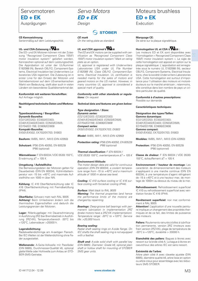
Les moteurs ED et EK sont disponibles avecl'homologation « Recognized Component Claas155(F) motor insulation system ». Le sigle decette homologation est apposé en option sur laplaque signalétique. L'approbation est enregis-trée sous le numéro UL E182088 (N), secteurOBJY2, Component-Systems, Electrical Insula-tions, chez la société Underwriters LaboratoriesUSA. Cette homologation est surtout d'impor-tance pour l'utilisation des moteurs et motoré-ducteurs sur le marché américain ; néanmoins,elle constitue dans bon nombre de pays un cri-tère particulier de qualité.
Conformité à d'autres prescriptions:
Possible sur demande
Caractéristiques techniques:
Désignation des types/Tailles:
Gamme dynamique:
ED212/ED203; ED302/ED303;ED401/ED402/ED403; ED503/ED505; ED704/ED706; ED806/ED808Gamme compact:
EK501/EK502; EK702/EK703; EK803
Modèles: IMB5, IMV1, IMV3 (DIN 42950)
Protection: IP56 (DIN 40050, EN 60529)IP66 (optionnel)
Classe de chaleur: F (EN 60034 / VDE 0530)155°C, échauffement DT = 105 K
Environnement / hauteur de montage: Lescaractérist. de dimensionnement des moteurss'appliquent à une marche continue (DIN EN60034), à une température d'agent réfrigérantde -15 à +40°C et à une hauteur max. de mon-tage de 1000m au-dessus du niveau de la mer.
Refroidissement: Refroidissement superficielIC 410 ou refroidissement superficiel avec ven-tilation forcée IC 416 (IP44).
Revêtement superficiel: noir mat conformé-ment à RAL 9005Attention! L’application d’une nouvelle peintu-re implique un changement des propriétés ther-miques et de ce fait, des limites de puissancedes moteurs.
Paliers: Roulements rainurés à billes à lubrifica-tion permanente, version 2RZ (moteurs avecfrein version 2RZ-KK), plage de température de-30°C à +120°C, durabilité > 20000 h.
Etanchéité des paliers: Bagues à lèvres avecressort sur la bride côté A. La bague à lèvres encaoutchouc des arbres IEC est sans ressort.
Extrémité de I’arbre:
Arbre plein côté A avec clavette ajustée (DIN6885), diamètre qualité k6, arbre lisse en optionou arbre creux pour assemblage avec les réduc-teurs SMS STÖBER.
Moteurs brushless ED + EKExécution
CE mark
On the rating plate as standard.
UL and CSA approval
The ED and EK motors can be supplied with cer-tification as "Recognized Component Class155(F) motor insulation system”. Mark on ratingplate as an option.UL approval is registered with UnderwritersLaboratories USA under UL File NumberE182088 (N), Class OBJY2, Component-Sys-tems, Electrical Insulation. UL certification isneeded mainly for the sales of motors andgeared motors on the US market. However, inmany countries UL approval is considered aspecial mark of quality.
Conformity with other standards or regula-
tions: On request
Technical data and features are given below:
Type designation / Sizes:
Dynamic series:
ED212/ED203; ED302/ED303;ED401/ED402/ED403; ED503/ED505; ED704/ED706; ED806/ED808Compact series:
EK501/EK502; EK702/EK703; EK803
Model: IMB5, IMV1, IMV3 (DIN 42950)
Protection rating: IP56 (DlN 40050, EN 60529)IP66 (optional)
Thermal classification: F (EN 60034 /VDE 0530) 155°C, overtemperature DT = 105 K
Environment/Altitude:
The motor design data are valid for continuousoperation (DIN EN 60034), a coolant tempera-ture range from -15 to +40°C and a maximumaltitude of 1000 m above sea level.
Cooling: IC 410 surface cooling or IC 416 sur-face cooling with forced-air cooling (IP44).
Surface: Matt black to RAL 9005Warning: The thermal properties (and hencethe performance limits of the motors) arechanged by repainting.
Bearings: Deep-groove ball bearings with per-manent lubrication in implementation 2RZ(brake motors have a 2RZ-KK implementation).Temperature range: -30°C to +120°C. Servicelife: >20,000 hours.
Bearing sealing:
Radial shaft sealing rings on A-side flange. OnIEC shafts the shaft sealing ring is not equippedwith a feather.
Shaft end: A-side solid shaft with parallel key(DIN 6885). Diameter: Grade k6, optional plainshaft or hollow shaft for mounting of STÖBERSMS gear units.
Servo Motors ED + EKDesign
CE-Kennzeichnung
Serienmäßig auf dem Leistungsschild.
UL- und CSA-Zulassung
Die ED- und EK-Motoren können mit der Zulas-sung “Recognized Component Class 155(F)motor insulation system” geliefert werden.Kennzeichen optional auf dem Leistungsschild.Die Approbation ist unter der UL-NummerE182088 (N), Bereich OBJY2, Component-Sys-tems, Electrical Insulation bei Underwriters La-boratories USA registriert. Die Zulassung ist inerster Linie für den Einsatz der Motoren undGetriebemotoren auf dem US-amerikanischenMarkt von Bedeutung, stellt aber auch in vielenLändern ein besonderes Qualitätsmerkmal dar.
Konformität mit weiteren Vorschriften:
Auf Anfrage möglich.
Nachfolgend technische Daten und Merkma-
le:
Typenbezeichnung / Baugrößen:
Dynamik-Baureihe:
ED212/ED203; ED302/ED303;ED401/ED402/ED403; ED503/ED505; ED704/ED 706; ED806/ED808Kompakt-Baureihe:
EK501/EK502; EK702/EK703; EK803
Bauform: IMB5, IMV1, IMV3 (DIN 42950)
Schutzart: IP56 (DIN 40050, EN 60529)IP66 (optional)
Wärmeklasse: F (EN 60034 / VDE 0530) 155°C,Erwärmung DT = 105 K
Umgebung / Aufstellhöhe:
Die Bemessungsdaten der Motoren gelten fürDauerbetrieb (DIN EN 60034), Kühlmitteltem-peratur von -15 bis +40°C und maximale Auf-stellhöhe von 1000 m über NN.
Kühlung: IC 410 Oberflächenkühlung oder IC416 Oberflächenkühlung mit Fremdbelüftung(IP44).
Oberfläche: Schwarz matt nach RAL 9005Achtung! Beim Umlackieren ändern sich diethermischen Eigenschaften und dadurch dieLeistungsgrenzen der Motoren.
Lager: Rillenkugellager mit Dauerschmierungin Ausführung 2RZ (bei Bremsbetrieb in Ausfüh-rung 2RZ-KK), Temperaturbereich -30°C bis+120°C, Lebensdauer >20000 h.
Lagerabdichtung:
Radialwellendichtringe am A-seitigen Flansch.Bei IEC-Wellen ist der Wellendichtring ohne Fe-der ausgestattet.
Wellenende: A-Seite-Vollwelle mit Passfeder(DIN 6885), Durchmesser-Qualität k6, optionalglatte Welle oder Hohlwelle zum Anbau an STÖ-BER-SMS-Getriebe.
Servomotoren ED + EKAusprägungen
ID 441712.04 - 12.09 M3www.stoeber.de
MM
Amplitude d'oscillation:
Niveau A en DIN EN 60034-14 (09/2004) enstandard ou niveau B en DIN EN 60034-14(09/2004) sur demande.
Niveau sonore:
Valeurs-limites pour moteurs selon EN 60034-9, pour réducteurs selon VDI 2159.
Précision de cylindricité, coaxialité et planéi-
té (DIN 42955):
Tolérance N
Résistance aux secousses:
Les limites maximales de secousses suivantessont admissibles pour un mouvement quasi si-nusoïdal d'au plus 1 kHz des moteurs ED et EK:avec/sans frein: au max. 5 g Attention! Sur des freins intégrés, la sollicita-tion oscillatoire peut avoir une incidence sur lescouples de maintien des freins et ces derniersne sont éventuellement plus entièrement dis-ponibles.
Bobinage:
Triphasé dans les plaques mobiles du stator,connexion étoile, centre non sorti. Repérage encouleur des torons de raccordement: U (U1) -noir, V (V1) - bleu, W (W1)-rouge.En fonction de la variante de bobinage (KE = 40;60; 70; 100; 110; 140 et 210 V/1000 min-1) et dela tension de circuit intermédiaire (UZK = 540
VDC), vitesses de mesure de 2000 - 6000 min-1
possibles (valeurs standard). Se référer égale-ment aux Caractéristiques Techniques présen-tées aux pages M10 - M11.Protection enroulement:
Tous les moteurs de la série ED et EK sont équi-pés d'une protection enroulement thermique.Il s'agit de thermistance triple selon CIE 34-11-2 ou DIN 44081 / 44082, c'est-à-dire trois ther-mistances PTC (à coefficient de températurepositif) montées en série dont respectivementune par phase est incorporée à l'enroulementce qui permet une surveillance des trois phasesmoteur.Les thermistances PTC sont des résistances àsemi-conducteurs dépendantes de la tempéra-ture qui, à atteinte de la température nominalede fonctionnement (TNF), augmentent brus-quement la résistance ohmique d'un multiplece qui active les systèmes de commande / decontrôle correspondants afin d'assurer la pro-tection de l'enroulement moteur contre tousdommages provoqués par suréchauffement.Cette protection moteur / protection enroule-ment thermique est appropriée notammentpour le mode par à-coups, le mode cyclique etla charge intermittente lorsque des pointes decharge supérieures à la puissance nominale sur-viennent en permanence comme c'est généra-lement le cas dans des applications d'asservis-sement.Les servoconvertisseurs STÖBER POSI-DRIVE® MDS 5000 et POSIDYN® SDS 5000sont munis de raccordements pour thermis-tances PTC et sont étalonnés pour les thermis-tances triples utilisées dans les moteurs brush-less STÖBER. Un raccordement correct de laprotection moteur thermique au servoconver-tisseur est donné en utilisant les câbles pré-as-semblés de STÖBER.
Moteurs brushless ED + EKExécution
Vibration severity:
A in acc. to DIN EN 60034-14 (09/2004) is stan-dard or B in acc. to DIN EN 60034-14 (09/2004)on request.
Noise level:
Limit values for motors per EN 60034-9, forgear unit per VDI 2159.
Rotational accuracy, coaxiality and axial ec-
centricity (DIN 42955):
Tolerance N
Vibratory load:
The following maximum vibration limits are per-missible for quasi-sinusoidal movements up to1 kHz of ED and EK motors:without/with brake max. 5 gCaution! Remember that with built-in brakesthe holding torques of the brakes may be affect-ed by the oscillation load and possibly no longercompletely available.
Winding:Three-phase in stator core stack, starconnection, centre point not fed out. Colourcoding of the connection leads: U (U1) - black,V (V1) - blue, W (W1) - red.Depending on the winding variance (KE = 40;60; 70; 100; 110; 140 and 210 V/1000 rpm) andthe DC link voltage (VDC link = 540 VDC) ratedspeeds from 2000 to 6000 rpm are possible(standard values). See also Technical data onpages M10 - M11.
Winding protection:
All motors of the model series ED and EK arestandardly equipped with thermal winding pro-tection. These are positor line triplets in accor-dance with IEC 34-11-2 or DIN 44081/44082(i.e., three, switched-in-series PTC thermistors(PTC = Positive Temperature Coefficient) oneeach of which is integrated per branch in thewinding. This ensures that all three motor phas-es are monitored.PTC thermistors are temperature-dependentsemi-conductor resistors which suddenly in-crease the ohmic resistance many times overwhen the nominal triggering temperature (NAT)is reached. This activates appropriatecontrol/monitoring systems to protect the mo-tor winding from damage caused by overheat-ing. This thermal motor protection/winding protec-tion is particularly suitable for surge operation,switching operation and interruption load whenload peaks greater than the nominal power oc-cur continuously as is usually the case with ser-vo applications.
STÖBER servo inverters POSIDRIVE® MDS5000 and POSIDYN® SDS 5000 are standardlyequipped with connections for PTC thermistorsand are calibrated for the positor line tripletsused by STÖBER servo motors. Together withavailable prefabricated STÖBER cables, correctconnection of the thermal motor protection onthe servo inverter is ensured.
Servo Motors ED + EKDesign
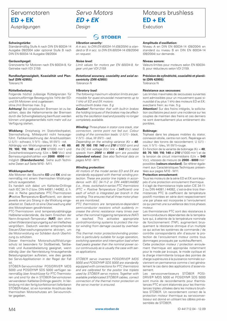
Schwingstärke:
Standardmäßig Stufe A nach DIN EN 60034-14Ausgabe 09/2004 oder optional Stufe B nachDIN EN 60034-14 Ausgabe 09/2004
Geräuschpegel:
Grenzwerte für Motoren nach EN 60034-9, fürGetriebe nach VDI 2159.
Rundlaufgenauigkeit, Koaxialität und Plan-
lauf (DIN 42955):
Toleranz N
Rüttelbelastung:
Folgende höchst zulässige Rüttelgrenzen fürquasisinusförmige Bewegung bis 1kHz der ED-und EK-Motoren sind zugelassen:ohne /mit Bremse max. 5 gAchtung! Bei eingebauten Bremsen ist zu be-achten, dass die Haltemomente der Bremsendurch die Schwingbelastung beinflusst werdenkönnen und gegebenenfalls nicht mehr voll zurVerfügung stehen.
Wicklung: Dreiphasig im Statorblechpaket,Sternschaltung, Mittelpunkt nicht herausge-führt. Farbkennzeichnung der Anschlusslitzen:U (U1) - schwarz, V (V1) - blau, W (W1) - rot.Abhängig von Wicklungsvarianz (KE = 40; 60;70; 100; 110; 140 und 210 V/1000 min-1) undZwischenkreisspannung (UZK = 540 VDC) sindBemessungsdrehzahlen von 2000 - 6000 min-1
möglich (Standardwerte). Siehe auch Techni-sche Daten auf Seite M10 - M11.
Wicklungsschutz:
Alle Motoren der Baureihe ED und EK sind se-rienmäßig mit einem thermischen Wicklungs-schutz ausgestattet.Es handelt sich dabei um Kaltleiter-Drillingenach IEC 34-11-2 bzw. DIN 44081 / 44082, d. h.drei in Reihe geschaltete PTC-Thermistoren(Positive Temperature Coefficient), von denenjeweils einer pro Strang in die Wicklung einge-arbeitet ist. Dadurch ist eine Überwachung allerdrei Motorphasen gewährleistet.PTC-Thermistoren sind temperaturabhängigeHalbleiterwiderstände, die beim Erreichen derNenn-Ansprech-Temperatur (NAT) den ohm-schen Widerstand sprungartig auf ein Vielfachesvergrößern. Dadurch werden entsprechendeSteuer-/Überwachungssysteme aktiviert, umdie Motorwicklung vor Schäden durch Überhit-zung zu schützen.Dieser thermische Motorschutz/Wicklungs-schutz ist besonders für Stoßbetrieb, Taktbe-trieb und Aussetzbelastung geeignet, wennständig über die Nennleistung hinausgehendeBelastungsspitzen auftreten, wie dies geradebei Servo-Applikationen in der Regel der Fallist.STÖBER-Servoumrichter POSIDRIVE® MDS5000 und POSIDYN® SDS 5000 verfügen se-rienmäßig über Anschlüsse für PTC-Thermisto-ren und sind für die in STÖBER-Servomotorenverwendeten Kaltleiter-Drillinge geeicht. In Ver-bindung mit den fertig konfektioniert lieferbarenSTÖBER-Kabel, ist ein korrekter Anschluss desthermischen Motorschutzes am Servoumrich-ter gegeben.
Servomotoren ED + EKAusprägungen
ID 441712.04 - 12.09M4 www.stoeber.de

REMARQUE: il est impératif de procéder à
un raccordement correct de la protection
moteur thermique pour éviter tout domma-
ge matériel ou corporel! Un raccordement
incorrect pourra entraîner la perte des droits
à la garantie! Il se peut à cet effet que l'utili-
sation de déclencheurs soit requise!
Caractéristiques techniques thermistors
montés en trifil:
Tension de service, UB = 7,5 V maxiRésistance à froid, R25 [ 750 �Résistance à NAT, RNAT m 3990 �Temps de réaction thermique, ta < 5 s
Code couleur thermistance:
Classe thermique F (155°C)NAT 145°CCouleur fil toronné noir/blanc (connexions interchangeables)
Codeur:
Codeur absolues EnDat® inductif ou optiqueexécution Singleturn ou Multiturn. En alternative des résolveurs bi-pôles de préci-sion.Informations complémentaires voir page M20.
Freins: Freins à ressort intégré en standardpour moteurs taille ED4-ED8. En alternativefreins d’arrêt sans jeu à aimant permanent (nonpar ED8).Pour les moteurs ED2-ED3 et EK5-EK8 freinsd’arrêt sans jeu sont standard à aimant perma-nent. Caractéristiques techn. à la page M18.
Ventilation forcée (conformément à DIN EN
60034-6, IC416): Des systèmes de ventilationforcée (IP44) sont mis en oeuvre dans I’objec-tif d’accroître les couples permanents ou lespuissances permanentes des moteurs ED etEK ou en cas de température ambiante élevée.Constituées de manches d’air variables et demoteurs de ventilation forcée, ces unités peu-vent être également commandées en tant quekit complémentaire pour montage utérieur (nepas ED2 et ED3). Caractéristiques techniques à la page M21.
Connexions:
Puissance/Codeur
ED2/ED3: Connexion enfichable/Connexion enfichable
ED4-ED8, Connexion enfichable/EK5 - EK8: Connexion enfichable
en optionBoîtier à bornes/
Connexion enfichable
cf. schémas des connexions aux pages M22 -M24
Interface de puissance:
Connexion enfichable:
Plié, orientable dans toutes les directions, livréavec/ sans pendant (selon demande du client).Pour les tailles ED2/ED3, pos. A+B, les fichesne sont pas placées exactement en ligne parrapport à l´axe moteur.
Moteurs brushless ED + EKExécution
NOTE: To prevent property damage or per-
sonal injury, correct connection of the ther-
mal motor protection must always be en-
sured. Otherwise the warranty may be inval-
idated!
Use of appropriate triggering devices is
sometimes required!
Technical data PTC thermistor triplets:
Operating voltage, UB = max. 7.5 VCold resistance R25 [ 750 �Resistance at NAT, RNAT m 3990 �Thermal response time, ta < 5 s
Color identifier for positor line:
Heat class F (155 °C)NAT 145 °CFlexible lead color: black/white (connections can be interchanged)
Encoder:
Inductive or optical EnDat® absolute value en-coders in singleturn or multiturn design as stan-dard.Alternatively 2-pole precision resolvers.For further information see page M20.
Brakes: Low backlash spring applied brakes asstandard on motor size ED4-ED8. As an optionbacklash-free permanent magnet holdingbrakes are available (not for ED8).Motor size ED2-ED3 and EK5-EK8 have a back-lash-free permanent magnet holding brake asstandard. Technical data: see page M18.
Forced-air cooling fan (acc. to DIN EN 60034-
6, IC416): Forced-air cooling systems (IP44) areused to increase the continuous torques andcontinuous outputs of the ED and EK motors,or for higher ambient temperatures. Theseunits, which consist of variable fan cowls andexternal fan motors can also be ordered as aretrofit kit and installed as a modification (notvalid for ED2 and ED3). Technical data: see page M21.
Method of connection:
Power/encoder
ED2/ED3: pin-and-socket connector/pin-and-socket connector
ED4-ED8, pin-and-socket connector/EK5-EK8: pin-and-socket connector
as an optionterminal box/
pin-and-socket connector
see wiring diagrams on pages M22 - M24
Power interface:
Pin-and-socket connector:
Bent, rotatable in any position, delivery with /without counter connector (acc. to customer re-quest).With motor size ED2/ED3, pos. A + B, the con-nectors are not exactly aligned to the motor ax-is.
Servo Motors ED + EKDesign
HINWEIS: Zum Schutz vor Sach- oder Perso-
nenschäden ist grundsätzlich ein korrekter
Anschluss des thermischen Motorschutzes
sicherzustellen. Andernfalls kann dies zum
Verlust der Garantie-Ansprüche führen! Un-
ter Umständen ist dazu die Verwendung ent-
sprechender Auslösegeräte erforderlich!
Technische Daten Kaltleiter-Drillinge:
Betriebsspannung, UB = max. 7,5 VKaltwiderstand, R25 [ 750 �Widerstand bei NAT, RNAT m 3990 �Thermische Ansprechzeit, ta < 5 s
Farbkennzeichnung für Kaltleiter:
Wärmeklasse F (155°C)NAT 145°CLitzenfarbe schwarz/weiß (Anschlüsse vertauschbar)
Encoder:
Induktive oder optische EnDat®-Absolutwertge-ber in Singleturn- oder Multiturn-Ausführung.Alternativ 2-polige Resolver in Präzisionsaus-führung.Näheres siehe Seite M20.
Bremsen:
Standardmäßig spielarme Federdruckbremsenfür Bgr. ED4 - ED8. Optional spielfreiepermanentmagneterregte Haltebremse (aus-genommen ED8).Motoren der Baugröße ED2-ED3 und EK5-EK8werden im Standard mit spielfreier perma-nentmagneterregter Haltebremse geliefert.Technische Daten siehe Seite M18.
Fremdlüfter (nach DIN EN 60034-6, IC416):
Um die Dauerdrehmomente bzw. Dauerleistun-gen der ED- und EK-Motoren zu erhöhen oderfür höhere Umgebungstemperaturen werdenFremdlüftersysteme (IP44) eingesetzt. Beste-hend aus variablen Lüfterhauben und Fremdlüft-ermotoren können diese Einheiten auch alsNachrüst-Kit bestellt und nachträglich angebautwerden (nicht für ED2 und ED3). Technische Daten siehe Seite M21.
Anschlusstechnik:
Leistung/Encoder
ED2/ED3: Steckverbinder/Steckverbinder
ED4-ED8, Steckverbinder/SteckverbinderEK5-EK8: optional
Klemmenkasten/Steckverbinder
siehe Anschlusspläne Seite M22 - M24
Leistungsschnittstelle:
Steckverbinder:
Abgewinkelt, drehbar in alle Positionen, Liefe-rung mit / ohne Gegenstecker (nach Kunden-wunsch).Bei der Baugröße ED2/ED3, Pos. A + B, sind dieStecker nicht exakt fluchtend zur Motorachseeinstellbar.
Servomotoren ED + EKAusprägungen
ID 441712.04 - 12.09 M5www.stoeber.de
MM

Boîtier à bornes (en option):
2 borniers pivotants sur 180° dotés de 3 orificesmétrique (voir aussi M22).Matériau: aluminium. Interfaces de connexion:tablette à bornes réalisées en un matériau dehaute qualité, avec dénomination deconnexions conformes à EN 60034-8.Boulon de blocage: ED4 - ED5 / EK5: M5
ED7 / EK7: M6ED8 / EK8: M8
Les raccords métrique ne sont pas comprisdans le volume de livraison. L'utilisation decâbles blindés et de raccords métrique avecconnexion au blindage des câbles est recom-mandée dans l'objectif de garantir un câblagerépondant aux exigences posées en matière decompatibilité électromagnétique.
Sortie de câble: voir illustr. en bas
Interface de codeur: connecteurs de codeurenfichables à 12 pôles disponibles en standard,17 pôles disponibles en option (voir page M23et M24).
Moteurs brushless ED + EKExécution
Sortie de câble:
Sortie de câble boîte à bornes standard côte L.Les fiches de connexion de puissance et de co-deur sont orientables dans toutes les direc-tions.
Terminal box (option):
2 x 180° terminal boxes rotatable with 3 metriccable entries (also see page M22). Material: aluminum. Points of terminal connec-tion: terminal blocks of high-quality materialwith terminal markings to EN 60034-8.Clamp bolt: ED4 - ED5 / EK5: M5
ED7 / EK7: M6ED8 / EK8: M8
Metric glands are not included in the scope ofdelivery. For EMC-compliant cabling shieldedcables and metric glands with connection of thecable shield are recommended.
Cable entry: see pictures below
Encoder interface:
12-pin encoder connectors are standard, 17-pincontrol as an option (see page M23 and M24).
Servo Motors ED + EKDesign
Cable entry:
Standard cable entry terminal box side L. Pow-er and encoder connectors are both rotatable inany position.
Klemmenkasten (Option):
2 x 180° drehbare Klemmenkästen mit 3 metri-schen Gewindebohrungen (siehe auch SeiteM22).Material: Aluminium. Anschluss-SchnittstellenKlemmbretter aus hochwertigem Material mitAnschlussbezeichnungen nach EN 60034-8.Klemmbolzen: ED4 - ED5 / EK5: M5
ED7 / EK7: M6ED8 / EK8: M8
Metrische Verschraubungen gehören nicht zumLieferumfang. Für EMV-gerechte Verkabelungsind abgeschirmte Leitungen und metrischeVerschraubungen mit Kabelschirmverbindungempfohlen.
Kabeleinführung: siehe unten
Encoderschnittstelle:
Standard 12-polige Encodersteckverbinder, op-tional 17-polig (siehe Seite M23 und M24).
Servomotoren ED + EKAusprägungen
Kabeleinführung:
Kabeleinführung Klemmenkasten standard-mäßig Seite L. Leistungs- und Encodersteckver-binder drehbar in alle Positionen.
ID 441712.04 - 12.09M6 www.stoeber.de
ED4 - ED8
EK5 - EK8
ED2 - ED8
EK5 - EK8

ED401USFM140 EK501BROM140
Moteurs brushless ED + EKDésignation des types
1 Type de moteurED - Gamme dynamiqueEK - Gamme compact
2 Taille du moteur
3 Nombre de génération
4 Nombre de segments de rotor
5 VentilationU - ventilation à mainB - ventilation forcée
6 CodeurR - RésolveurM - Codeur absolues EnDat®
multiturn inductif pour MDS 5000 / SDS 5000
S - Codeur absolues EnDat®
singleturn inductif pour MDS 5000 / SDS 5000
G - Codeur absolues EnDat® 2.2multiturn optique pour SDS 5000
H - Codeur absolues EnDat® 2.2singleturn optique pour SDS 5000
7 FreinO - sans freinP - frein permanent magnetiqueF - frein à ressort intégré
8 ServoconvertisseursM - POSIDRIVE® MDS 5000P - POSIDYN® SDS 5000G - MDS / SDS 5000 Sin-Cos
9 Bobinage(constante KE en V/1000 min-1)
Pour toute commande, indiquer les spécifica-tions de la dénomination du moteur concernée.Autres lettres possibles pour frappages spé-ciaux.
Servo Motors ED + EKType designation
1 Motor typeED - Dynamic seriesEK - Compact series
2 Motor size
3 Generation number
4 Number of rotor segments
5 VentilationU - self-ventilatedB - forced cooled
6 EncoderR - ResolverM - Multiturn EnDat® absolute value
encoder inductive for MDS 5000 / SDS 5000
S - Singleturn EnDat® absolute valueencoder inductive for MDS 5000 / SDS 5000
G - Multiturn EnDat® 2.2 absolutevalue encoder optical for SDS 5000
H - Singleturn EnDat® 2.2 absolutevalue encoder optical for SDS 5000
7 BrakeO - without brakeP - permanent magnet brakeF - spring applied brake
8 Servo Inverters M - POSIDRIVE® MDS 5000P - POSIDYN® SDS 5000G - MDS / SDS 5000 Sin-Cos
9 Winding(KE constant in V/1000 rpm)
Ordering data according to the type designationabove.During special development other letters arepossible.
Servomotoren ED + EKTypenbezeichnung
1 MotortypED - Dynamik-BaureiheEK - Kompakt-Baureihe
2 Motorgröße
3 Generationsziffer
4 Anzahl Rotorsegmente
5 BelüftungU - unbelüftetB - fremdbelüftet
6 EncoderR - ResolverM - Multiturn EnDat®-Absolutwertgeber
induktiv für MDS 5000 / SDS 5000S - Singleturn EnDat®-Absolutwertgeber
induktiv für MDS 5000 / SDS 5000G - Multiturn EnDat® 2.2 Absolut-
wertgeber optisch für SDS 5000H - Singleturn EnDat® 2.2 Absolut-
wertgeber optisch für SDS 5000
7 BremseO - ohne BremseP - PermanentmagnetbremseF - Federdruckbremse
8 ServoumrichterM - POSIDRIVE® MDS 5000P - POSIDYN® SDS 5000G - MDS / SDS 5000 Sin-Cos
9 Wicklung(KE-Konstante in V/1000 min-1)
Bestellangaben entsprechend obiger Typisie-rung.Bei Sonderausprägung andere Buchstabenmöglich.
ID 441712.04 - 12.09 M7www.stoeber.de
MM
ED 4 0 1 U S F M 140
| | | | | | | | |1 2 3 4 5 6 7 8 9

KM M
lMR=
+( )0
0
M K I M NmN M R= ⋅ − [ ]
KM M
lMR=
+( )0
0
M K I M NmN M R= ⋅ − [ ]
KM M
lMR=
+( )0
0
M K I M NmN M R= ⋅ − [ ]
Tension de circuit intermédiaire, UZK [VDC]
Valeur de mesure de la tension AC connectéeet redressée d'un servoconvertisseur.Constante de tension FÉM,
KE [V/1000 min-1]
La valeur KE est la valeur maximale de la tensioninduite et enchaînée à un température de servi-ce de 105 K et à 1000 min-1 à vide génératrice.Les valeurs indiquées (sur le catalogue et laplaque signalétique) ont une tolérance de±10%.Constante de couple de rotation KM [Nm/A]
Cette valeur KM est constante sur toute la pla-ge fonctionnelle (M, n) d'un moteur ED / EK etdépend de la variante de bobinage (KE). La valeur KM est le quotient du couple interne(Couple d’immobilisation M0 et couple de fric-tion MR) au rotor ( M0 et MR) et courant I0 (valeurefficace): il s'agit du quotient spécifique pourune variante de bobinage KE. Tolérance: ±10%
Facteur de couple de rotation KMN [Nm/A]
Un rapport non linéaire du courant de IO à IN, parconséquent aussi du couple MO à MN, est gé-néré par des pertes internes (couples de frotte-ment, pertes par hystérésis, pertes par cou-rants de Foucault et résistances de contactthermiques). C’est pourquoi le facteur de couple de rotationKMN à une vitesse nominale nN est spécifié pourles points assignés significatifs MN et IN.
Couple de friction MR [Nm]
La valeur MR est le couple de friction du palieret des joints d'un moteur ED et EK à une tem-pérature de 100°C.
Vitesse de mesure nN [min-1]
La valeur nN est la vitesse de mesure d'unecombinaison de la constante de tension du mo-teur KE et de la tension du circuit intermédiairedu convertisseur en présence du couple de me-sure MN.
Couple de mesure MN [Nm]
La valeur MN est le couple de durée limite d'unmoteur en présence de la vitesse de mesurenN. Cette valeur a une tolérance de ±5%. Parconséquence, le point de mesure est définipar les valeurs nN et MN. D'autres couples derotation peuvent être calculés sur la base ducourant selon les formules suivantes :
Diagramme couple de rotation / vitesse
Cette valeur est une diagramme constante parmoteur ED et EK (voir pages M12 - M16) illus-trant le rapport existant entre le couple de me-sure et la vitesse de mesure pour une marchecontinue S1, un échauffement maximal de 105K (classe de chaleur F) et des fonctions (para-mètres) énergétiques optimales du servocon-vertisseur. Cette diagramme est applicable àtoutes les variantes de bobinage KE.
^
Moteurs brushless ED + EKFormules
DC link voltage, UZK [VDC]
Rated value of the rectified AC supply voltageof a servo inverter.
Back EMF constant, KE [V/1000 rpm]
KE is the peak value of the induced delta volt-age at an operating temperature of 105 K and1000 rpm at regenerative no load. The valuesgiven in the catalog and on the rating plate havea tolerance of ± 10%.
Torque constant KM [Nm/A]
KM is a constant over the entire operating range(M, n) of an ED / EK motor, depending on itswinding variant (KE). KM is defined by the quotient of inner torque(Stall torque M0 and friction torque MR) at therotor (M0 + MR) and current I0 (rms value), spe-cific to a winding variant (KE). Tolerance: ± 10%
Torque factor KMN [Nm/A]
Inner losses (friction moments, hysteresis loss-es, eddy current losses and thermal contact re-sistances) cause the creation of a non-linear ra-tio of the current of I0 to IN and thus also the mo-ment M0 to MN.This is why the torque factor KMN is specified forthe relevant rated points MN and IN with ratedspeed nN.
Friction torque, MR [Nm]
MR is the bearing friction and sealing torque ofan ED and EK motor at 100°C.
Rated speed, nN [rpm]
nN is the rated speed of a motor kE + inverterDC link voltage combination at MN.
Rated torque, MN [Nm]
MN is the peak continuous torque of a motor atnN, tolerance: ±5%, i.e. the rated working
point is defined by nN and MN. Further torquevalues can be computed using the formula:
Torque/speed characteristic
A constant characteristic for every ED and EKmotor (see M12 - M16) showing the relation-ship of rated torque and rated speed for S1 con-tinuous duty. Maximum heating to 105 K (insu-lation class F) and energy-optimized servo in-verter functions (settings). Applies to all KE
winding variants.
Servo Motors ED + EKFormulas
^
Zwischenkreisspannung, UZK [VDC]
Bemessungswert der gleichgerichteten AC-An-schluss-Spannung eines Servoumrichters.
EMK-Spannungskonstante, KE
[V/1000 min-1]
KE ist der Scheitelwert der verketteten, induzier-ten Spannung bei Betriebstemperatur 105 Kund 1000 min-1 im generatorischen Leerlauf. Dieangegebenen Werte (Katalog und Leistungs-schild) sind mit ±10% Toleranz behaftet.Drehmomentkonstante, KM [Nm/A]
KM ist eine Konstante im gesamten Funktions-bereich (M, n) eines ED-/ EK-Motors, abhängigvon seiner Wicklungsvariante (KE). KM errechnet sich aus dem Quotienten von in-nerem Drehmoment (StillstandsdrehmomentM0 und Reibungsmoment MR) am Rotor (M0 +MR) und Strom I0 (Effektivwert), spezifisch für je-de Wicklungsvariante (KE). Toleranz: ± 10%
Drehmomentfaktor, KMN [Nm/A]
Durch innere Verluste (Reibungsmomente, Hys-tresseverluste, Wirbelstromversluste und ther-mische Übergangswiderstände) entsteht einnichtlineares Verhältnis des Stromes von I0 zu INund somit auch des Momentes M0 zu MN.Daher wird der Drehmomentfaktor KMN bei Be-messungsdrehzahl nN für die relevanten Be-messungspunkte MN und IN angegeben.
Reibungsmoment, MR [Nm]
MR ist das Lagerreibungs- u. Dichtungsmomentbei 100°C eines ED- /EK-Motors.
Bemessungsdrehzahl, nN [min-1]
nN ist die Bemessungsdrehzahl einer Motor-kE+Umrichter-Zwischenkreisspannungs-Kombi-nation bei MN.
Bemessungsdrehmoment, MN [Nm]
MN ist das Höchstdauerdrehmoment eines Mo-tors bei nN, Toleranz: ±5%, somit ist derBemessungspunkt durch nN und MN definiert.Weitere Drehmomentwerte können über diefolgende Formel näherungsweise berechnetwerden:
Drehmoment / Drehzahl Kennlinie
ist eine pro ED-/EK-Motor konstante Kennlinie(siehe M12 - M16), welche die Abhängigkeit desBemessungsdrehmomentes von der Bemes-sungsdrehzahl für S1-Dauerbetrieb zeigt, Höch-sterwärmung 105 K (Wärmeklasse F) und ener-getisch optimale Servoumrichter-Funktionen(Einstellungen). Gilt für alle KE-Wicklungsvarian-ten.
Servomotoren ED + EKFormelzeichen
^
ID 441712.04 - 12.09M8 www.stoeber.de
Les valeurs de mesure sont applicables seule-ment pour fonctions (paramètres) énergétiquesoptimales du servoconvertisseur dans lesconditions thermiques de montage suivantes :Moteur Bride de montage Surface
ED + EK acier de montage
SxBxH [mm] [m2]ED212/203 20 x 210 x 285 0.03ED302/303 20 x 210 x 285 0.03ED401/402/403 20 x 210 x 285 0.03ED503/505 25 x 210 x 285 0.03ED806/808 25 x 285 x 285 0.03EK501/502 25 x 210 x 285 0.03EK702/703 25 x 285 x 285 0.03EK803 25 x 285 x 285 0.03Courant de mesure IN [A]
La valeur IN est le courant permanent corres-pondant au point de mesure et dependent à lavariante de bobinage (KE). Cette valeur a une tolérance de ±5%.Puissance de mesure PN [kW]
PN est la puissance sur l'arbre que le moteurpeut fournir en permanence au point assignérespectif, tolérance: ± 5%. Couple d'immobilisation M0 [Nm]
La valeur M0 est le couple continu à une vites-se 10. Cette valeur a une tolérance de ±5%.Courant d'immobilisation I0 [A]
I0 est le courant passant à M0 dependent à lavariante de bobinage (KE). Cette valeur a une tolérance de ±5%.Couple de rotation maximal Mmax [Nm]
La valeur Mmax est le couple maximal admis-sible à court terme à l'accélération ou au freina-ge. Cette valeur a une tolérance de +10%.Courant maximal Imax [A]
Imax est l'intensité maximale appartenant àMmax à laquelle le moteur peut être alimentétemporairement en fonction de la variante d'en-roulement (KE). Tolérance: ±5%.Condition requise: réglage énergétique optimaldu servoconvertisseur. Imax et Mmax sont deslimites destinées à la protection du moteur. Undépassement de ces limites risque de provo-quer des dommages irréversibles du rotor (dé-magnétisation).Résistance de bobinage Ru-v [��]
La valeur Ru-v est la résistance de bobinage d'un moteur ED et EK entre deux phases à 20°C.Inductivité de bobinage Lu-v [mH]
La valeur Lu-v est l'inductivité de bobinage d'unmoteur ED / EK entre deux phases (rechercheselon le principe de courant oscillant).Constante de temps électrique Tel [ms]
La valeur Tel décrit la hausse de courant d'unmoteur ED / EK à 20°C. Elle est le quotient deLu-v/Ru-v.Couple d'inertie de masse J [10-4kgm2]
Masse de moteur sans frein, m [kg]
Courbes limites de tension
Les courbes indiquent les combinaisons vi-tesses/couples maximales en marche de cour-te durée. Lorsque la tension monte, des vi-tesses supérieures peuvent être atteintes; lescouples de rotation pouvant être obtenus dé-pendent également du courant maximal duconvertisseur (en valeur et en durée). Sur lesgénérations de servoconvertisseurs à correc-tion de courant optimisée, la courbe limite detension se décale vers le côté supérieur droit,ce qui permet d'atteindre des puissances supé-rieures. Voir aussi pages M12 - M16.
Moteurs brushless ED + EKFormules
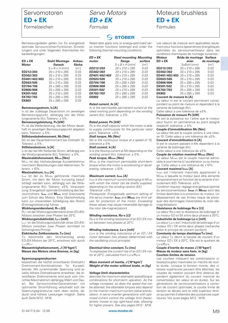
Rated data apply only to energy-optimized ser-vo inverter functions (settings) and under thefollowing thermal mounting conditions:
ED + EK Steel mounting Mounting
motor flange surface
S x B x H [mm] [m2]ED212/203 20 x 210 x 285 0.03ED302/303 20 x 210 x 285 0.03ED401/402/403 20 x 210 x 285 0.03ED503/505 25 x 210 x 285 0.03ED704/706 25 x 285 x 285 0.03ED806/808 25 x 285 x 285 0.03EK501/502 25 x 210 x 285 0.03EK702/703 25 x 285 x 285 0.03EK803 25 x 285 x 285 0.03
Rated current, IN [A]
IN is the permissible permanent current at therated working point depending on the windingvariant (KE), tolerance: ± 5%.
Rated power, PN [kW]
PN is the shaft capacity which the motor is ableto supply continuously for the particular ratedpoint. Tolerance: +5%. Stall torque, M0 [Nm]
M0 is the continuous torque at a speed of 10,tolerance ± 5%.Stall current, I0 [A]
I0 is the flowing current at M0 depending on thewinding variant (KE), tolerance: ± 5%.Peak torque, Mmax [Nm]
Mmax is the maximum permissible short-termtorque when the motor is accelerating or decel-erating, tolerance: +10%.
Maximum current, Imax [A]
Imax is the maximum current belonging to Mmax
with which the motor can be briefly supplied,depending on the winding version (KE).Tolerance: +5%. Prerequisite: Energetically optimum setting ofthe servo inverter. Imax and Mmax are limit val-ues for protection of the motor. Exceedingthese values may cause irreversible damage tothe rotor (de-magnetization).
Winding resistance, Ru-v [��]
Ru-v is the winding resistance of an ED / EK mo-tor between two phases at 20°C.
Winding inductance, Lu-v [mH]
Lu-v is the winding inductance of an ED / EKmotor between two phases (determined withthe oscillating circuit principle).
Electrical time constant,Tel [ms]
Tel expresses the current rise of an ED / EK mo-tor at 20°C, calculated from Lu-v/Ru-v.
Mass moment of inertia, J [10-4kgm2]
Weight of the motor without brake, m [kg]
Voltage limit characteristics
describe the maximum attainable speed/torquecombinations for short-term operation. As thevoltage increases, so does the speed that canbe attained; the attainable torques also dependon the inverter maximum current (value and du-ration). In servo inverter generations with opti-mized current control the voltage limit charac-teristic moves to top right-hand side, allowingfor higher powers. See also pages M12 - M16.
Servo Motors ED + EKFormulas
Bemessungsdaten gelten nur für energetischoptimale Servoumrichter-Funktionen (Einstel-lungen) und unter folgenden thermischen An-baubedingungen:
ED + EK Stahl Montage- Anbau-
Motor flansch fläche
S x B x H [mm] [m2]ED212/203 20 x 210 x 285 0.03ED302/303 20 x 210 x 285 0.03ED401/402/403 20 x 210 x 285 0.03ED503/505 25 x 210 x 285 0.03ED704/706 25 x 285 x 285 0.03ED806/808 25 x 285 x 285 0.03EK501/502 25 x 210 x 285 0.03EK702/703 25 x 285 x 285 0.03EK803 25 x 285 x 285 0.03
Bemessungsstrom, IN [A]
IN ist der zulässige Dauerstrom im jeweiligenBemessungspunkt, abhängig von der Wick-lungsvariante (KE), Toleranz: ± 5%.Bemessungsleistung, PN [kW]
PN ist die Wellenleistung, die der Motor dauer-haft im jeweiligen Bemessungspunkt abgebenkann, Toleranz: ± 5%.Stillstandsdrehmoment, M0 [Nm]
M0 ist das Dauerdrehmoment bei Drehzahl 10,Toleranz: ± 5%.Stillstandsstrom, I0 [A]
I0 ist der bei M0 fließende Strom, abhängig vonder Wicklungsvariante (KE), Toleranz: ± 5%.Maximaldrehmoment, Mmax [Nm]
Mmax ist das höchstzulässige Kurzzeitdrehmo-ment beim Beschleunigen oder Abbremsen, To-leranz: +10%.Maximalstrom, Imax [A]
Imax ist der zu Mmax gehörende maximaleStrom, mit dem der Motor kurzzeitig beauf-schlagt werden kann, abhängig von der Wick-lungsvariante (KE). Toleranz: ±5%. Vorausset-zung: Energetisch optimale Einstellung des Ser-voumrichters. Imax und Mmax sind Grenzwertezum Schutz des Motors. Eine Überschreitungkann zur irreversiblen Schädigung des Rotors(Entmagnetisierung) führen.Wicklungswiderstand, RU-V [��]
RU-V ist der Wicklungswiderstand eines ED-/EK-Motors zwischen zwei Phasen bei 20°C.Wicklungsinduktivität, LU-V [mH]
LU-V ist die Wicklungsinduktivität eines ED-/EK-Motors zwischen zwei Phasen (ermittelt imSchwingkreis-Prinzip).Elektrische Zeitkonstante,Tel [ms]
Tel beschreibt den Stromanstieg einesED-/EK-Motors bei 20°C, errechnet sich durchLU-V/RU-V
Massenträgheitsmoment, J [10-4kgm2]
Masse des Motors ohne Bremse, m [kg]
Spannungsgrenzkurven
bezeichnen die höchst erreichbaren Drehzahl-/Drehmoment-Kombinationen für Kurzzeit-betrieb. Mit zunehmender Spannung sind je-weils höhere Drehzahlwerte erreichbar; die er-reichbaren Drehmomente sind auch vom Um-richter-Maximalstrom abhängig (Wert und Dau-er). Bei Servoumrichter-Generationen mitoptimierter Stromführung verschiebt sich dieSpannungsgrenzkurve nach oben rechts, da-durch sind höhere Leistungen möglich. Sieheauch Seite M12 - M16.
Servomotoren ED + EKFormelzeichen
ID 441712.04 - 12.09 M9www.stoeber.de
MM

Moteurs brushless ED Caractéristiques techniques
Tension de circuit intermédiaire 540 V CC,
620 V maxi (servo convertisseur STÖBER)
avec ventilation externe IC 416
sans ventilation IC 410
Moteurs ED212 et ED203 sont exécutés à 4 pôles.
Autres moteurs sont exécutés à 6 pôles.
Servo Motors ED Technical data
DC link voltage 540 V DC, max. 620 V
(STÖBER servo inverters)
with external ventilation IC 416
non ventilated IC 410
Motors ED212 and ED203 come in 4 pole design. All
other motors come in 6 pole design.
Servomotoren ED Technische Daten
Zwischenkreisspannung 540 V DC,
max. 620 V (STÖBER Servo-Umrichter)
fremdbelüftet IC 416
unbelüftet IC 410
Motoren ED212 und ED203 sind 4-polig, alle anderen
Motoren sind 6-polig ausgeführt.
Mot. KE nN MN IN KMN PN M0 I0 KM MR Mmax Imax RU-V LU-V Tel J m
[V^ min/ [min-1] [Nm] [A] [Nm/A] [kW] [Nm] [A] [Nm/A] [Nm] [Nm] [A] [W] [mH] [ms] [10-4 [kg]1000] kgm2]
ED401B 70 6000 2,45 3,50 0,700 1,5 3,19 3,84 0,849 0,070 12,5 16,0 7,50 14,50 1,93 1,41 5,30ED401B 140 3000 3,00 1,96 1,531 0,94 3,19 2,05 1,590 0,070 12,5 8,00 29,60 43,90 1,48 1,41 5,30ED402B 70 6000 4,98 6,35 0,784 3,1 6,52 7,99 0,825 0,070 24,0 30,0 2,51 7,90 3,15 2,51 6,92ED402B 140 3000 5,97 3,75 1,594 1,9 6,52 4,06 1,624 0,070 24,0 15,0 8,90 22,80 2,56 2,51 6,92ED403B 70 6000 6,50 8,90 0,730 4,1 8,78 10,9 0,810 0,070 29,0 36,0 1,42 4,57 3,22 3,61 8,48ED403B 140 3000 8,10 5,56 1,457 2,5 8,78 5,89 1,503 0,070 29,0 20,0 5,20 15,80 3,04 3,61 8,48ED503B 70 6000 9,20 12,1 0,760 5,8 11,8 15,6 0,761 0,110 32,0 42,0 0,78 3,60 4,62 8,25 11,6ED503B 140 3000 10,8 7,33 1,473 3,4 11,8 7,80 1,522 0,110 32,0 22,0 2,95 12,05 4,09 8,25 11,6ED505B 100 4200 17,8 15,7 1,134 7,8 20,2 17,5 1,161 0,110 63,6 63,0 0,78 5,00 4,97 13,2 16,0ED505B 140 3000 17,5 12,4 1,411 5,5 20,2 14,1 1,440 0,110 63,6 45,0 1,55 7,70 4,97 13,2 16,0ED704B 100 4200 23,2 19,8 1,172 10 26,0 21,7 1,212 0,230 63,2 52,0 0,54 4,85 8,98 28,4 22,2ED704B 140 3000 22,8 14,7 1,556 7,2 26,0 15,8 1,660 0,230 63,2 40,0 1,05 7,40 7,05 28,4 22,2ED704B 210 2000 24,3 10,5 2,314 5,1 26,0 11,0 2,385 0,230 63,2 27,0 2,43 17,30 7,12 28,4 22,2ED706B 100 4200 29,4 24,7 1,190 13 38,8 31,6 1,235 0,230 91,0 82,0 0,31 3,20 10,32 41,8 29,2ED706B 140 3000 33,0 23,0 1,435 10 38,8 24,5 1,593 0,230 91,0 59,0 0,65 4,80 7,39 41,8 29,2ED706B 210 2000 36,2 15,8 2,291 7,6 38,8 16,7 2,337 0,230 91,0 39,0 1,25 10,90 8,72 41,8 29,2ED806B 100 4200 55,0 52,3 1,052 24 66,8 59,4 1,130 0,310 120 107 0,12 1,95 13,31 117 54,0ED806B 140 3000 52,8 37,4 1,412 17 66,8 42,6 1,575 0,310 120 77,0 0,23 3,10 13,31 117 54,0ED808B 110 4000 62,4 55,0 1,135 26 86,4 71,0 1,221 0,310 150 130 0,10 1,55 15,82 153 65,0ED808B 210 2000 67,2 30,6 2,196 14 86,4 37,1 2,337 0,310 150 64,0 0,36 5,20 14,40 153 65,0
Mot. KE nN MN IN KMN PN M0 I0 KM MR Mmax Imax RU-V LU-V Tel J m
[V^ min/ [min-1] [Nm] [A] [Nm/A] [kW] [Nm] [A] [Nm/A] [Nm] [Nm] [A] [W] [mH] [ms] [10-4 [kg]1000] kgm2]
ED212U 40 6000 0,44 1,07 0,411 0,28 0,48 1,12 0,452 0,026 1,48 3,48 26,00 15,80 0,61 0,13 1,43ED212U 40 3000 0,45 1,08 0,417 0,14 0,48 1,12 0,452 0,026 1,48 3,48 26,00 15,80 0,61 0,13 1,43ED203U 40 6000 0,52 1,18 0,441 0,33 0,65 1,43 0,473 0,026 2,72 5,84 19,00 14,45 0,76 0,17 1,67ED203U 40 3000 0,60 1,29 0,465 0,19 0,65 1,43 0,473 0,026 2,72 5,84 19,00 14,45 0,76 0,17 1,67ED302U 60 6000 0,88 1,30 0,677 0,55 1,09 1,63 0,688 0,031 3,92 6,08 20,40 26,40 1,29 0,44 2,27ED302U 60 3000 0,98 1,52 0,645 0,31 1,09 1,63 0,688 0,031 3,92 6,08 20,40 26,40 1,29 0,44 2,27ED303U 60 6000 1,15 1,70 0,677 0,72 1,41 2,12 0,680 0,031 5,40 7,48 10,30 17,75 1,72 0,61 2,77ED303U 110 3000 1,35 1,10 1,227 0,42 1,41 1,14 1,264 0,031 5,40 4,32 40,25 46,00 1,14 0,61 2,77ED401U 70 6000 1,90 2,77 0,686 1,2 2,51 3,02 0,854 0,070 12,5 16,0 7,50 14,50 1,93 1,41 3,90ED401U 140 3000 2,36 1,54 1,533 0,74 2,51 1,61 1,603 0,070 12,5 8,00 29,60 43,90 1,48 1,41 3,90ED402U 70 6000 3,80 4,85 0,784 2,4 4,98 6,10 0,828 0,070 24,0 30,0 2,51 7,90 3,15 2,51 5,52ED402U 140 3000 4,56 2,86 1,594 1,4 4,98 3,10 1,629 0,070 24,0 15,0 8,90 22,80 2,56 2,51 5,52ED403U 70 6000 4,25 5,85 0,727 2,7 6,60 8,22 0,811 0,070 29,0 36,0 1,42 4,57 3,22 3,61 7,08ED403U 140 3000 5,94 4,18 1,421 1,9 6,60 4,43 1,506 0,070 29,0 20,0 5,20 15,80 3,04 3,61 7,08ED503U 70 6000 4,35 5,80 0,750 2,7 9,00 11,9 0,766 0,110 32,0 42,0 0,78 3,60 4,62 8,25 9,66ED503U 140 3000 7,60 5,16 1,473 2,4 9,00 5,95 1,531 0,110 32,0 22,0 2,95 12,05 4,09 8,25 9,66ED505U 100 4200 11,1 9,90 1,121 4,9 14,1 12,2 1,170 0,110 63,6 63,0 0,78 5,00 4,97 13,2 14,1ED505U 140 3000 12,0 8,52 1,409 3,8 14,1 9,83 1,441 0,110 63,6 45,0 1,55 7,70 4,97 13,2 14,1ED704U 100 4200 14,6 12,3 1,187 6,4 19,6 16,1 1,232 0,230 63,2 52,0 0,54 4,85 8,98 28,4 19,3ED704U 140 3000 16,5 11,0 1,500 5,2 19,6 12,5 1,589 0,230 63,2 40,0 1,05 7,40 7,05 28,4 19,3ED704U 210 2000 17,8 7,67 2,321 3,7 19,6 8,32 2,383 0,230 63,2 27,0 2,43 17,30 7,12 28,4 19,3ED706U 100 4200 15,1 13,1 1,153 6,6 27,5 22,5 1,232 0,230 91,0 82,0 0,31 3,20 10,32 41,8 26,3ED706U 140 3000 21,7 14,5 1,497 6,8 27,5 17,8 1,562 0,230 91,0 59,0 0,65 4,80 7,39 41,8 26,3ED706U 210 2000 23,5 10,2 2,295 4,9 27,5 11,8 2,344 0,230 91,0 39,0 1,25 10,90 8,72 41,8 26,3ED806U 100 4200 22,0 21,5 1,023 9,7 47,0 42,2 1,121 0,310 120 107 0,12 1,95 13,31 117 49,0ED806U 140 3000 30,0 20,4 1,471 9,4 47,0 30,2 1,567 0,310 120 77,0 0,23 3,10 13,31 117 49,0ED808U 110 4000 10,2 10,0 1,020 4,3 58,0 48,5 1,202 0,310 150 130 0,10 1,55 15,82 153 60,0ED808U 210 2000 45,1 20,6 2,194 9,4 58,0 24,9 2,339 0,310 150 64,0 0,36 5,20 14,40 153 60,0
www.stoeber.de ID 441712.04 - 12.09M10

Moteurs brushless EKCaractéristiques techniques
Tension de circuit intermédiaire 540 V CC,
620 V maxi (servo convertisseur STÖBER)
sans ventilation IC 410
avec ventilation externe IC 416
Les moteurs sont exécutés à 6 pôles.
Servo Motors EKTechnical data
DC link voltage 540 V DC, max. 620 V
(STÖBER servo inverters)
non ventilated IC 410
with external ventilation IC 416
All motors come in 6 pole design.
Servomotoren EK Technische Daten
Zwischenkreisspannung 540 V DC,
max. 620 V (STÖBER Servo-Umrichter)
unbelüftet IC 410
fremdbelüftet IC 416
Alle Motoren sind 6-polig ausgeführt.
Mot. KE nN MN IN KMN PN M0 I0 KM MR Mmax Imax RU-V LU-V Tel J m
[V^ min/ [min-1] [Nm] [A] [Nm/A] [kW] [Nm] [A] [Nm/A] [Nm] [Nm] [A] [W] [mH] [ms] [10-4 [kg]1000] kgm2]
EK501B 70 6000 3,75 5,04 0,744 2,4 4,33 5,47 0,812 0,110 15,0 20,0 3,82 10,90 2,85 3,19 7,87EK501B 140 3000 4,00 2,63 1,521 1,3 4,33 2,73 1,626 0,110 15,0 10,0 15,70 35,70 2,27 3,19 7,87EK502B 70 6000 7,60 8,95 0,849 4,8 9,45 10,8 0,885 0,110 20,0 25,0 1,43 5,10 3,57 5,67 9,34EK502B 140 3000 8,70 5,69 1,529 2,7 9,45 5,87 1,629 0,110 20,0 12,5 5,50 18,55 3,37 5,67 9,34EK702B 140 3000 13,0 8,51 1,528 4,1 13,9 8,74 1,611 0,230 36,0 24,0 2,94 15,00 5,10 15,5 15,5EK702B 210 2000 13,4 5,70 2,351 2,8 13,9 5,82 2,419 0,230 36,0 16,0 5,65 31,40 5,56 15,5 15,5EK703B 140 3000 18,2 11,0 1,655 5,7 19,7 11,8 1,696 0,230 50,0 31,0 1,80 10,70 5,94 21,9 18,8EK703B 210 2000 18,9 7,55 2,503 4,0 19,7 7,85 2,539 0,230 50,0 20,7 3,48 21,27 6,11 21,9 18,8EK803B 140 3000 30,8 21,7 1,420 9,7 35,0 22,5 1,569 0,310 60,0 39,3 0,61 6,00 9,84 63,1 37,0
Mot. KE nN MN IN KMN PN M0 I0 KM MR Mmax Imax RU-V LU-V Tel J m
[V^ min/ [min-1] [Nm] [A] [Nm/A] [kW] [Nm] [A] [Nm/A] [Nm] [Nm] [A] [W] [mH] [ms] [10-4 [kg]1000] kgm2]
EK501U 70 6000 2,60 3,50 0,743 1,6 3,36 4,24 0,818 0,110 15,0 20,0 3,82 10,90 2,85 3,19 5,97EK501U 140 3000 3,10 2,04 1,520 0,97 3,36 2,12 1,637 0,110 15,0 10,0 15,70 35,70 2,27 3,19 5,97EK502U 70 6000 4,20 5,00 0,840 2,6 6,53 7,70 0,862 0,110 20,0 25,0 1,43 5,10 3,57 5,67 7,44EK502U 140 3000 5,88 3,85 1,527 1,8 6,53 4,06 1,636 0,110 20,0 12,5 5,50 18,55 3,37 5,67 7,44EK702U 140 3000 9,80 6,40 1,531 3,1 10,7 6,72 1,619 0,230 36,0 24,0 2,94 15,00 5,10 15,5 12,6EK702U 210 2000 10,2 4,32 2,350 2,1 10,7 4,48 2,429 0,230 36,0 16,0 5,65 31,40 5,56 15,5 12,6EK703U 140 3000 13,4 8,32 1,611 4,2 15,0 9,04 1,685 0,230 50,0 31,0 1,80 10,70 5,94 21,9 15,9EK703U 210 2000 14,1 5,70 2,474 3,0 15,0 6,02 2,530 0,230 50,0 20,7 3,48 21,27 6,11 21,9 15,9EK803U 140 3000 21,6 14,9 1,450 6,8 25,2 16,5 1,546 0,310 60,0 39,3 0,61 6,00 9,84 63,1 32,0
ID 441712.04 - 12.09 M11www.stoeber.de
MM

ED203U
0,0
0,5
1,0
1,5
2,0
2,5
3,0
3,5
4,0
0 1000 2000 3000 4000 5000 6000 7000
n [min-1]
M [N
m]
M
Mmax
KE 40VpED212U
0,0
0,5
1,0
1,5
2,0
2,5
3,0
0 1000 2000 3000 4000 5000 6000 7000
n [min-1]
M [N
m]
Mmax
M
KE 40Vp
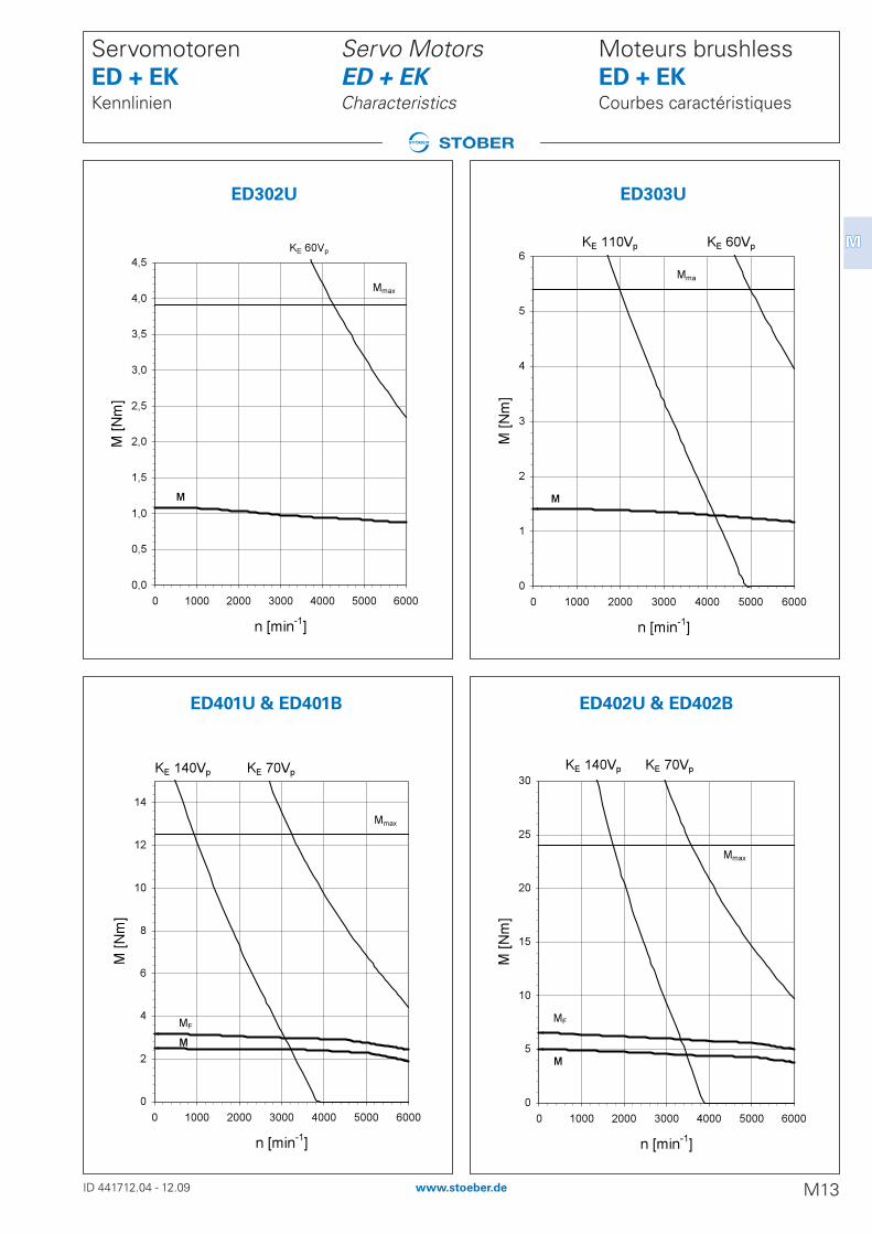
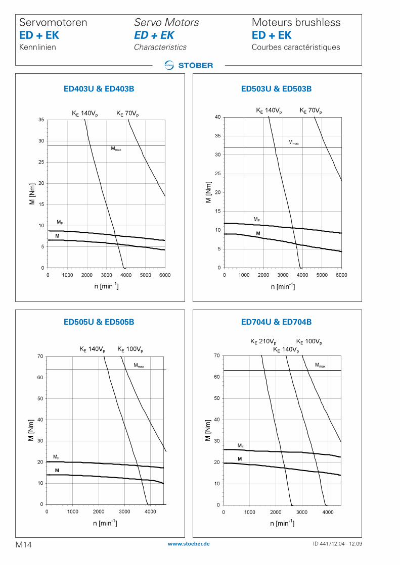
Kennlinien-Erklärung:
M - DrehmomentMF - Drehmoment bei FremdlüftungMmax - Maximal-DrehmomentKEXXX - Spannungsgrenzkurve
Der Verlauf dieser Grenzkurven ist abhängig von der Kombination derWicklungsvarianten (KE-Faktoren) und den Zwischenkreisspannun-gen der jeweiligen Servoumrichter.
Characteristics explanation:
M - TorqueMF - Torque with forced-air coolingMmax - Maximum torqueKEXXX - Voltage limit curve
The shape of these limit curves depends upon the combination ofwinding variants (KE factors) and the DC link voltage of the particularservo inverters.
Courbes caractéristiques explication:
M - CoupleMF - Couple avec ventilation forcéeMmax - Couple maximumKEXXX - Courbe limite de tension
Le tracé de ces courbes limite dépend de la combinaison des va-riantes de bobinage (facteurs KE) et des tensions de circuit intermé-diaire des servoconvertisseurs respectifs.
Moteurs brushless ED + EKCourbes caractéristiques
Servo Motors ED + EKCharacteristics
Servomotoren ED + EKKennlinien
ID 441712.04 - 12.09M12 www.stoeber.de
BeispielExampleExemple
ED212U ED203U
ED402U & ED402B
ED303U
0
1
2
3
4
5
6
0 1000 2000 3000 4000 5000 6000
n [min-1]
M [N
m]
Mma
M
KE 60VpKE 110Vp
ED302U
0,0
0,5
1,0
1,5
2,0
2,5
3,0
3,5
4,0
4,5
0 1000 2000 3000 4000 5000 6000
n [min-1]
M [N
m]
Mmax
M
KE 60Vp
ED401U & ED401B
0
2
4
6
8
10
12
14
0 1000 2000 3000 4000 5000 6000
n [min-1]
M [N
m]
Mmax
MMF
KE 70VpKE 140Vp
ED402U & ED402B
0
5
10
15
20
25
30
0 1000 2000 3000 4000 5000 6000
n [min-1]
M [N
m]
Mmax
MF
M
KE 140Vp KE 70Vp
Moteurs brushless ED + EKCourbes caractéristiques
Servo Motors ED + EKCharacteristics
Servomotoren ED + EKKennlinien
ID 441712.04 - 12.09 M13www.stoeber.de
MM
ED302U ED303U
ED402U & ED402BED401U & ED401B
ED403U & ED403B
0
5
10
15
20
25
30
35
0 1000 2000 3000 4000 5000 6000
n [min-1]
M [N
m]
Mmax
MF
M
KE 140Vp KE 70Vp
ED503U & ED503B
0
5
10
15
20
25
30
35
40
0 1000 2000 3000 4000 5000 6000
n [min-1]
M [N
m]
Mmax
M
MF
KE 140Vp KE 70Vp
ED505U & ED505B
0
10
20
30
40
50
60
70
0 1000 2000 3000 4000
n [min-1]
M [N
m]
Mmax
M
MF
KE 140Vp KE 100Vp
ED704U & ED704B
0
10
20
30
40
50
60
70
0 1000 2000 3000 4000
n [min-1]
M [N
m]
Mmax
M
MF
KE 210VpKE 140Vp
KE 100Vp
Moteurs brushless ED + EKCourbes caractéristiques
Servo Motors ED + EKCharacteristics
Servomotoren ED + EKKennlinien
ID 441712.04 - 12.09M14 www.stoeber.de
ED403U & ED403B ED503U & ED503B
ED505U & ED505B ED704U & ED704B

ED706U & ED706B
0
20
40
60
80
100
0 1000 2000 3000 4000
n [min-1]
M [N
m]
Mmax
M
MF
KE 140Vp
KE 210Vp KE 100Vp
ED806U & ED806B
0
20
40
60
80
100
120
0 1000 2000 3000 4000
n [min-1]
M [N
m]
Mmax
M
MF
KE 140Vp KE 100Vp
ED808U & ED808B
0
20
40
60
80
100
120
140
160
0 1000 2000 3000 4000
n [min-1]
M [N
m]
Mmax
M
MF
KE 210Vp KE 110Vp
EK501U & EK501B
0
2
4
6
8
10
12
14
16
18
20
22
0 1000 2000 3000 4000 5000 6000
n [min-1]
M [N
m]
MF
M
Mmax
KE 140Vp KE 70Vp
Moteurs brushless ED + EKCourbes caractéristiques
Servo Motors ED + EKCharacteristics
Servomotoren ED + EKKennlinien
ID 441712.04 - 12.09 M15www.stoeber.de
MM
ED806U & ED806B
ED808U & ED808B
ED706U & ED706B
EK501U & EK501B

EK803U & EK803B
0
10
20
30
40
50
60
70
80
90
0 1000 2000 3000
n [min-1]
M [N
m]
Mmax
M
MF
KE 140Vp
EK502U & EK502B
0
2
4
6
8
10
12
14
16
18
20
22
24
26
0 1000 2000 3000 4000 5000 6000
n [min-1]
M [N
m]
Mmax
M
M
KE 140Vp KE 70Vp
EK702U & EK702B
0
5
10
15
20
25
30
35
0 1000 2000 3000
n [min-1]
M [N
m]
Mmax
MMF
KE 140VpKE 210Vp
EK703U & EK703B
0
5
10
15
20
25
30
35
40
45
50
55
60
0 1000 2000 3000
n [min-1]
M [N
m]
Mmax
M
MF
KE 210Vp KE 140Vp
MF
Moteurs brushless ED + EKCourbes caractéristiques
Servo Motors ED + EKCharacteristics
Servomotoren ED + EKKennlinien
ID 441712.04 - 12.09M16 www.stoeber.de
EK803U & EK803B
EK502U & EK502B EK702U & EK702B
EK703U & EK703B
Moteurs brushless ED + EKFrein
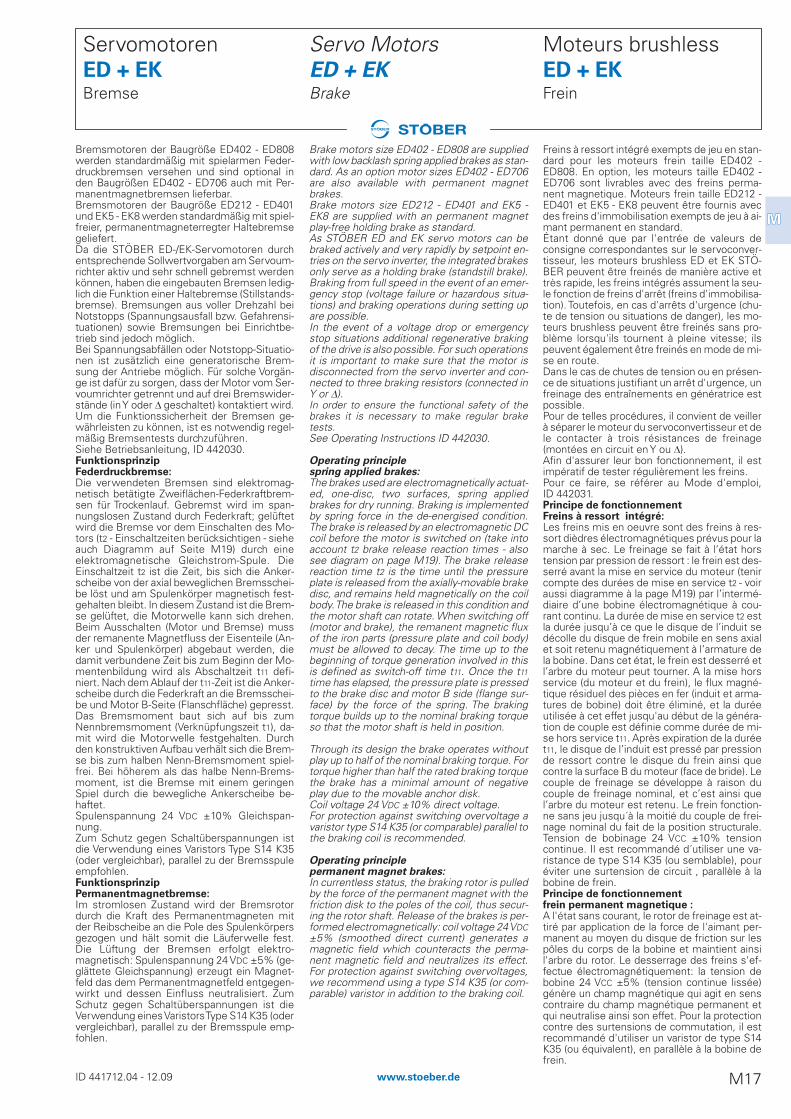
Freins à ressort intégré exempts de jeu en stan-dard pour les moteurs frein taille ED402 -ED808. En option, les moteurs taille ED402 -ED706 sont livrables avec des freins perma-nent magnetique. Moteurs frein taille ED212 -ED401 et EK5 - EK8 peuvent être fournis avecdes freins d'immobilisation exempts de jeu à ai-mant permanent en standard.Étant donné que par l'entrée de valeurs deconsigne correspondantes sur le servoconver-tisseur, les moteurs brushless ED et EK STÖ-BER peuvent être freinés de manière active ettrès rapide, les freins intégrés assument la seu-le fonction de freins d'arrêt (freins d'immobilisa-tion). Toutefois, en cas d'arrêts d'urgence (chu-te de tension ou situations de danger), les mo-teurs brushless peuvent être freinés sans pro-blème lorsqu'ils tournent à pleine vitesse; ilspeuvent également être freinés en mode de mi-se en route.Dans le cas de chutes de tension ou en présen-ce de situations justifiant un arrêt d'urgence, unfreinage des entraînements en génératrice estpossible. Pour de telles procédures, il convient de veillerà séparer le moteur du servoconvertisseur et dele contacter à trois résistances de freinage(montées en circuit en Y ou �).Afin d'assurer leur bon fonctionnement, il estimpératif de tester régulièrement les freins.Pour ce faire, se référer au Mode d'emploi,ID 442031.Principe de fonctionnement Freins à ressort intégré:Les freins mis en oeuvre sont des freins à res-sort dièdres électromagnétiques prévus pour lamarche à sec. Le freinage se fait à l’état horstension par pression de ressort : le frein est des-serré avant la mise en service du moteur (tenircompte des durées de mise en service t2 - voiraussi diagramme à la page M19) par l’intermé-diaire d’une bobine électromagnétique à cou-rant continu. La durée de mise en service t2 estla durée jusqu’à ce que le disque de l’induit sedécolle du disque de frein mobile en sens axialet soit retenu magnétiquement à l’armature dela bobine. Dans cet état, le frein est desserré etl’arbre du moteur peut tourner. A la mise horsservice (du moteur et du frein), le flux magné-tique résiduel des pièces en fer (induit et arma-tures de bobine) doit être éliminé, et la duréeutilisée à cet effet jusqu'au début de la généra-tion de couple est définie comme durée de mi-se hors service t11. Après expiration de la duréet11, le disque de l’induit est pressé par pressionde ressort contre le disque du frein ainsi quecontre la surface B du moteur (face de bride). Lecouple de freinage se développe à raison ducouple de freinage nominal, et c’est ainsi quel’arbre du moteur est retenu. Le frein fonction-ne sans jeu jusqu´à la moitié du couple de frei-nage nominal du fait de la position structurale.Tension de bobinage 24 VCC ±10% tensioncontinue. Il est recommandé d´utiliser une va-ristance de type S14 K35 (ou semblable), pouréviter une surtension de circuit , parallèle à labobine de frein.Principe de fonctionnement frein permanent magnetique :A l'état sans courant, le rotor de freinage est at-tiré par application de la force de l'aimant per-manent au moyen du disque de friction sur lespôles du corps de la bobine et maintient ainsil'arbre du rotor. Le desserrage des freins s'ef-fectue électromagnétiquement: la tension debobine 24 VCC ±5% (tension continue lissée)génère un champ magnétique qui agit en senscontraire du champ magnétique permanent etqui neutralise ainsi son effet. Pour la protectioncontre des surtensions de commutation, il estrecommandé d'utiliser un varistor de type S14K35 (ou équivalent), en parallèle à la bobine defrein.
Servo Motors ED + EKBrake
Brake motors size ED402 - ED808 are suppliedwith low backlash spring applied brakes as stan-dard. As an option motor sizes ED402 - ED706are also available with permanent magnetbrakes.Brake motors size ED212 - ED401 and EK5 -EK8 are supplied with an permanent magnetplay-free holding brake as standard.As STÖBER ED and EK servo motors can bebraked actively and very rapidly by setpoint en-tries on the servo inverter, the integrated brakesonly serve as a holding brake (standstill brake).Braking from full speed in the event of an emer-gency stop (voltage failure or hazardous situa-tions) and braking operations during setting upare possible.In the event of a voltage drop or emergencystop situations additional regenerative brakingof the drive is also possible. For such operationsit is important to make sure that the motor isdisconnected from the servo inverter and con-nected to three braking resistors (connected inY or �).In order to ensure the functional safety of thebrakes it is necessary to make regular braketests.See Operating Instructions ID 442030.
Operating principlespring applied brakes:The brakes used are electromagnetically actuat-ed, one-disc, two surfaces, spring appliedbrakes for dry running. Braking is implementedby spring force in the de-energised condition.The brake is released by an electromagnetic DCcoil before the motor is switched on (take intoaccount t2 brake release reaction times - alsosee diagram on page M19). The brake releasereaction time t2 is the time until the pressureplate is released from the axially-movable brakedisc, and remains held magnetically on the coilbody. The brake is released in this condition andthe motor shaft can rotate. When switching off(motor and brake), the remanent magnetic fluxof the iron parts (pressure plate and coil body)must be allowed to decay. The time up to thebeginning of torque generation involved in thisis defined as switch-off time t11. Once the t11time has elapsed, the pressure plate is pressedto the brake disc and motor B side (flange sur-face) by the force of the spring. The brakingtorque builds up to the nominal braking torqueso that the motor shaft is held in position.
Through its design the brake operates withoutplay up to half of the nominal braking torque. Fortorque higher than half the rated braking torquethe brake has a minimal amount of negativeplay due to the movable anchor disk.Coil voltage 24 VDC ±10% direct voltage.For protection against switching overvoltage avaristor type S14 K35 (or comparable) parallel tothe braking coil is recommended.
Operating principlepermanent magnet brakes:In currentless status, the braking rotor is pulledby the force of the permanent magnet with thefriction disk to the poles of the coil, thus secur-ing the rotor shaft. Release of the brakes is per-formed electromagnetically: coil voltage 24 VDC±5% (smoothed direct current) generates amagnetic field which counteracts the perma-nent magnetic field and neutralizes its effect.For protection against switching overvoltages,we recommend using a type S14 K35 (or com-parable) varistor in addition to the braking coil.
Servomotoren ED + EKBremse
Bremsmotoren der Baugröße ED402 - ED808werden standardmäßig mit spielarmen Feder-druckbremsen versehen und sind optional inden Baugrößen ED402 - ED706 auch mit Per-manentmagnetbremsen lieferbar.Bremsmotoren der Baugröße ED212 - ED401und EK5 - EK8 werden standardmäßig mit spiel-freier, permanentmagneterregter Haltebremsegeliefert.Da die STÖBER ED-/EK-Servomotoren durchentsprechende Sollwertvorgaben am Servoum-richter aktiv und sehr schnell gebremst werdenkönnen, haben die eingebauten Bremsen ledig-lich die Funktion einer Haltebremse (Stillstands-bremse). Bremsungen aus voller Drehzahl beiNotstopps (Spannungsausfall bzw. Gefahrensi-tuationen) sowie Bremsungen bei Einrichtbe-trieb sind jedoch möglich.Bei Spannungsabfällen oder Notstopp-Situatio-nen ist zusätzlich eine generatorische Brem-sung der Antriebe möglich. Für solche Vorgän-ge ist dafür zu sorgen, dass der Motor vom Ser-voumrichter getrennt und auf drei Bremswider-stände (in Y oder � geschaltet) kontaktiert wird.Um die Funktionssicherheit der Bremsen ge-währleisten zu können, ist es notwendig regel-mäßig Bremsentests durchzuführen.Siehe Betriebsanleitung, ID 442030.Funktionsprinzip Federdruckbremse:Die verwendeten Bremsen sind elektromag-netisch betätigte Zweiflächen-Federkraftbrem-sen für Trockenlauf. Gebremst wird im span-nungslosen Zustand durch Federkraft; gelüftetwird die Bremse vor dem Einschalten des Mo-tors (t2 - Einschaltzeiten berücksichtigen - sieheauch Diagramm auf Seite M19) durch eineelektromagnetische Gleichstrom-Spule. DieEinschaltzeit t2 ist die Zeit, bis sich die Anker-scheibe von der axial beweglichen Bremsschei-be löst und am Spulenkörper magnetisch fest-gehalten bleibt. In diesem Zustand ist die Brem-se gelüftet, die Motorwelle kann sich drehen.Beim Ausschalten (Motor und Bremse) mussder remanente Magnetfluss der Eisenteile (An-ker und Spulenkörper) abgebaut werden, diedamit verbundene Zeit bis zum Beginn der Mo-mentenbildung wird als Abschaltzeit t11 defi-niert. Nach dem Ablauf der t11-Zeit ist die Anker-scheibe durch die Federkraft an die Bremsschei-be und Motor B-Seite (Flanschfläche) gepresst.Das Bremsmoment baut sich auf bis zumNennbremsmoment (Verknüpfungszeit t1), da-mit wird die Motorwelle festgehalten. Durchden konstruktiven Aufbau verhält sich die Brem-se bis zum halben Nenn-Bremsmoment spiel-frei. Bei höherem als das halbe Nenn-Brems-moment, ist die Bremse mit einem geringenSpiel durch die bewegliche Ankerscheibe be-haftet.Spulenspannung 24 VDC ±10% Gleichspan-nung.Zum Schutz gegen Schaltüberspannungen istdie Verwendung eines Varistors Type S14 K35(oder vergleichbar), parallel zu der Bremsspuleempfohlen.FunktionsprinzipPermanentmagnetbremse:Im stromlosen Zustand wird der Bremsrotordurch die Kraft des Permanentmagneten mitder Reibscheibe an die Pole des Spulenkörpersgezogen und hält somit die Läuferwelle fest.Die Lüftung der Bremsen erfolgt elektro-magnetisch: Spulenspannung 24 VDC ±5% (ge-glättete Gleichspannung) erzeugt ein Magnet-feld das dem Permanentmagnetfeld entgegen-wirkt und dessen Einfluss neutralisiert. ZumSchutz gegen Schaltüberspannungen ist dieVerwendung eines Varistors Type S14 K35 (odervergleichbar), parallel zu der Bremsspule emp-fohlen.
ID 441712.04 - 12.09 M17www.stoeber.de
MM
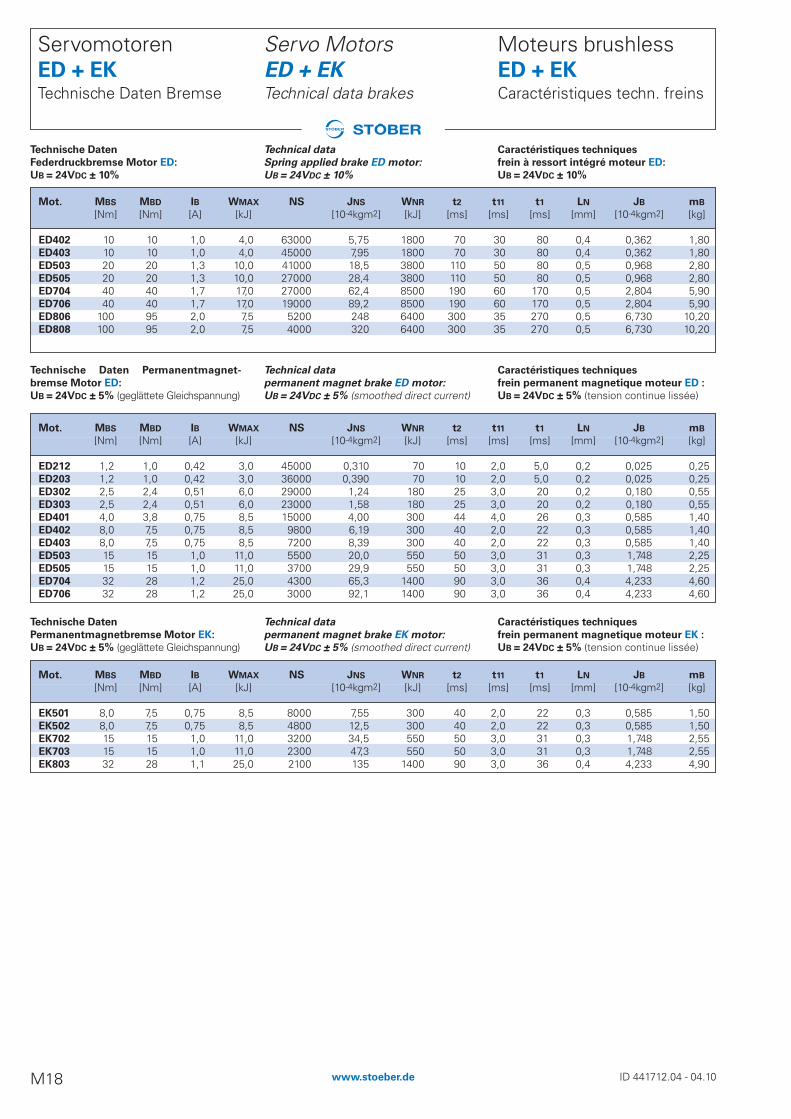
Caractéristiques techniques
frein à ressort intégré moteur ED:
UB = 24VDC ± 10%
Moteurs brushless ED + EKCaractéristiques techn. freins
Caractéristiques techniques
frein permanent magnetique moteur ED :
UB = 24VDC ± 5% (tension continue lissée)
Caractéristiques techniques
frein permanent magnetique moteur EK :
UB = 24VDC ± 5% (tension continue lissée)
Technical data
Spring applied brake ED motor:
UB = 24VDC ± 10%
Servo Motors ED + EKTechnical data brakes
Technical data
permanent magnet brake ED motor:
UB = 24VDC ± 5% (smoothed direct current)
Technical data
permanent magnet brake EK motor:
UB = 24VDC ± 5% (smoothed direct current)
Technische Daten
Federdruckbremse Motor ED:
UB = 24VDC ± 10%
Servomotoren ED + EKTechnische Daten Bremse
Technische Daten Permanentmagnet-
bremse Motor ED:
UB = 24VDC ± 5% (geglättete Gleichspannung)
Technische Daten
Permanentmagnetbremse Motor EK:
UB = 24VDC ± 5% (geglättete Gleichspannung)
Mot. MBS MBD IB WMAX NS JNS WNR t2 t11 t1 LN JB mB
[Nm] [Nm] [A] [kJ] [10-4kgm2] [kJ] [ms] [ms] [ms] [mm] [10-4kgm2] [kg]
ED402 10 10 1,0 4,0 63000 5,75 1800 70 30 80 0,4 0,362 1,80ED403 10 10 1,0 4,0 45000 7,95 1800 70 30 80 0,4 0,362 1,80ED503 20 20 1,3 10,0 41000 18,5 3800 110 50 80 0,5 0,968 2,80ED505 20 20 1,3 10,0 27000 28,4 3800 110 50 80 0,5 0,968 2,80ED704 40 40 1,7 17,0 27000 62,4 8500 190 60 170 0,5 2,804 5,90ED706 40 40 1,7 17,0 19000 89,2 8500 190 60 170 0,5 2,804 5,90ED806 100 95 2,0 7,5 5200 248 6400 300 35 270 0,5 6,730 10,20ED808 100 95 2,0 7,5 4000 320 6400 300 35 270 0,5 6,730 10,20
ID 441712.04 - 04.10M18 www.stoeber.de
Mot. MBS MBD IB WMAX NS JNS WNR t2 t11 t1 LN JB mB
[Nm] [Nm] [A] [kJ] [10-4kgm2] [kJ] [ms] [ms] [ms] [mm] [10-4kgm2] [kg]
ED212 1,2 1,0 0,42 3,0 45000 0,310 70 10 2,0 5,0 0,2 0,025 0,25ED203 1,2 1,0 0,42 3,0 36000 0,390 70 10 2,0 5,0 0,2 0,025 0,25ED302 2,5 2,4 0,51 6,0 29000 1,24 180 25 3,0 20 0,2 0,180 0,55ED303 2,5 2,4 0,51 6,0 23000 1,58 180 25 3,0 20 0,2 0,180 0,55ED401 4,0 3,8 0,75 8,5 15000 4,00 300 44 4,0 26 0,3 0,585 1,40ED402 8,0 7,5 0,75 8,5 9800 6,19 300 40 2,0 22 0,3 0,585 1,40ED403 8,0 7,5 0,75 8,5 7200 8,39 300 40 2,0 22 0,3 0,585 1,40ED503 15 15 1,0 11,0 5500 20,0 550 50 3,0 31 0,3 1,748 2,25ED505 15 15 1,0 11,0 3700 29,9 550 50 3,0 31 0,3 1,748 2,25ED704 32 28 1,2 25,0 4300 65,3 1400 90 3,0 36 0,4 4,233 4,60ED706 32 28 1,2 25,0 3000 92,1 1400 90 3,0 36 0,4 4,233 4,60
Mot. MBS MBD IB WMAX NS JNS WNR t2 t11 t1 LN JB mB
[Nm] [Nm] [A] [kJ] [10-4kgm2] [kJ] [ms] [ms] [ms] [mm] [10-4kgm2] [kg]
EK501 8,0 7,5 0,75 8,5 8000 7,55 300 40 2,0 22 0,3 0,585 1,50EK502 8,0 7,5 0,75 8,5 4800 12,5 300 40 2,0 22 0,3 0,585 1,50EK702 15 15 1,0 11,0 3200 34,5 550 50 3,0 31 0,3 1,748 2,55EK703 15 15 1,0 11,0 2300 47,3 550 50 3,0 31 0,3 1,748 2,55EK803 32 28 1,1 25,0 2100 135 1400 90 3,0 36 0,4 4,233 4,90
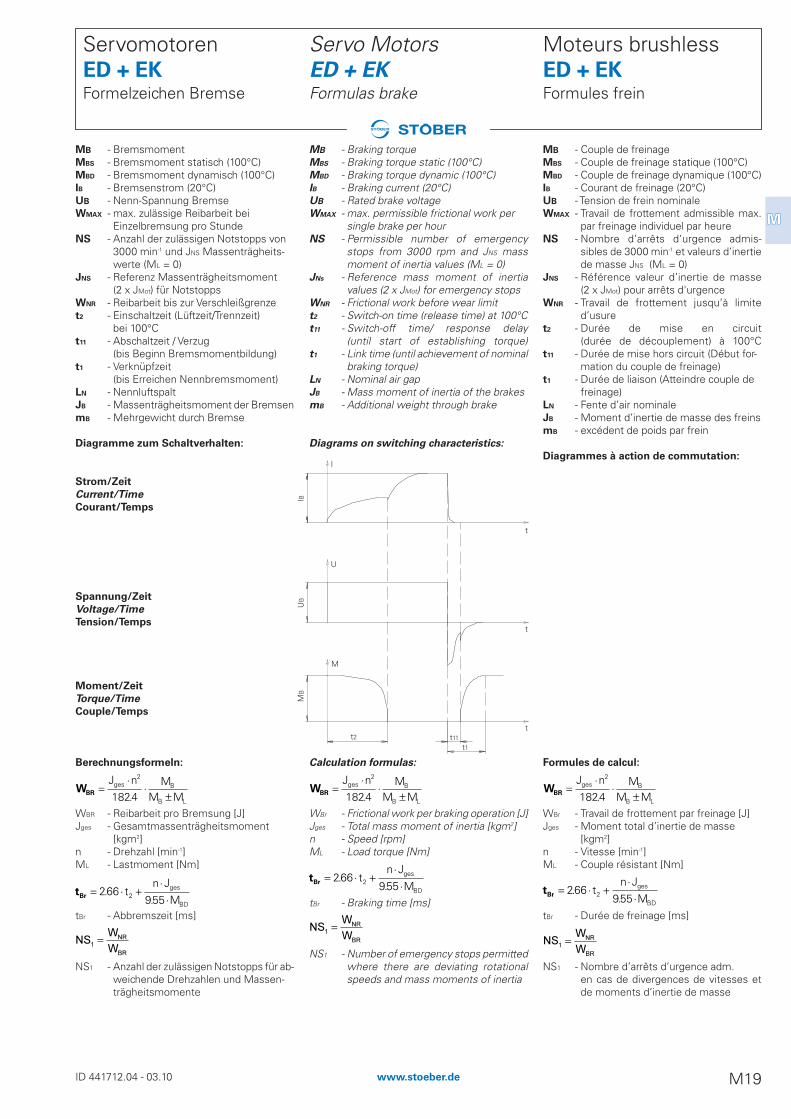
IBU
BM
B
t2 t11t1
t
t
t
M
U
WBR =⋅
⋅±
J n MM M
ges B
B L
2
1824.
tBr = ⋅ +⋅
⋅266
9552..
tn J
Mges
BD
NS1
=W
W
NR
BR
tBr = ⋅ +⋅
⋅266
9552..
tn J
Mges
BD
WBR =⋅
⋅±
J n MM M
ges B
B L
2
1824.
NS1
=W
W
NR
BR
WBR =⋅
⋅±
J n MM M
ges B
B L
2
1824.
tBr = ⋅ +⋅
⋅266
9552..
tn J
Mges
BD
NS1
=W
W
NR
BR
MB - Couple de freinageMBS - Couple de freinage statique (100°C)MBD - Couple de freinage dynamique (100°C)IB - Courant de freinage (20°C)UB - Tension de frein nominaleWMAX - Travail de frottement admissible max.
par freinage individuel par heureNS - Nombre d’arrêts d’urgence admis-
sibles de 3000 min-1 et valeurs d’inertie de masse JNS (ML = 0)
JNS - Référence valeur d’inertie de masse (2 x JMot) pour arrêts d'urgence
WNR - Travail de frottement jusqu’à limite d’usure
t2 - Durée de mise en circuit(durée de découplement) à 100°C
t11 - Durée de mise hors circuit (Début for-mation du couple de freinage)
t1 - Durée de liaison (Atteindre couple de freinage)
LN - Fente d’air nominaleJB - Moment d’inertie de masse des freinsmB - excédent de poids par frein
Diagrammes à action de commutation:
Formules de calcul:
WBr - Travail de frottement par freinage [J]Jges - Moment total d’inertie de masse
[kgm2]n - Vitesse [min-1]ML - Couple résistant [Nm]
tBr - Durée de freinage [ms]
NS1 - Nombre d’arrêts d’urgence adm. en cas de divergences de vitesses et de moments d’inertie de masse
Moteurs brushless ED + EKFormules frein
MB - Braking torqueMBS - Braking torque static (100°C)MBD - Braking torque dynamic (100°C)IB - Braking current (20°C)UB - Rated brake voltage WMAX - max. permissible frictional work per
single brake per hourNS - Permissible number of emergency
stops from 3000 rpm and JNS mass moment of inertia values (ML = 0)
JNs - Reference mass moment of inertia values (2 x JMot) for emergency stops
WNR - Frictional work before wear limitt2 - Switch-on time (release time) at 100°Ct11 - Switch-off time/ response delay
(until start of establishing torque)t1 - Link time (until achievement of nominal
braking torque)LN - Nominal air gapJB - Mass moment of inertia of the brakesmB - Additional weight through brake
Diagrams on switching characteristics:
Calculation formulas:
WBr - Frictional work per braking operation [J]Jges - Total mass moment of inertia [kgm2]n - Speed [rpm]ML - Load torque [Nm]
tBr - Braking time [ms]
NS1 - Number of emergency stops permittedwhere there are deviating rotationalspeeds and mass moments of inertia
Servo Motors ED + EKFormulas brake
MB - BremsmomentMBS - Bremsmoment statisch (100°C)MBD - Bremsmoment dynamisch (100°C)IB - Bremsenstrom (20°C)UB - Nenn-Spannung BremseWMAX - max. zulässige Reibarbeit bei
Einzelbremsung pro StundeNS - Anzahl der zulässigen Notstopps von
3000 min-1 und JNS Massenträgheits-werte (ML = 0)
JNS - Referenz Massenträgheitsmoment(2 x JMot) für Notstopps
WNR - Reibarbeit bis zur Verschleißgrenzet2 - Einschaltzeit (Lüftzeit/Trennzeit)
bei 100°Ct11 - Abschaltzeit / Verzug
(bis Beginn Bremsmomentbildung)t1 - Verknüpfzeit
(bis Erreichen Nennbremsmoment)LN - NennluftspaltJB - Massenträgheitsmoment der BremsenmB - Mehrgewicht durch Bremse
Diagramme zum Schaltverhalten:
Strom/Zeit
Current/Time
Courant/Temps
Spannung/Zeit
Voltage/Time
Tension/Temps
Moment/Zeit
Torque/Time
Couple/Temps
Berechnungsformeln:
WBR - Reibarbeit pro Bremsung [J]Jges - Gesamtmassenträgheitsmoment
[kgm2]n - Drehzahl [min-1]ML - Lastmoment [Nm]
tBr - Abbremszeit [ms]
NS1 - Anzahl der zulässigen Notstopps für ab-weichende Drehzahlen und Massen-trägheitsmomente
Servomotoren ED + EKFormelzeichen Bremse
ID 441712.04 - 03.10 M19www.stoeber.de
MM
I
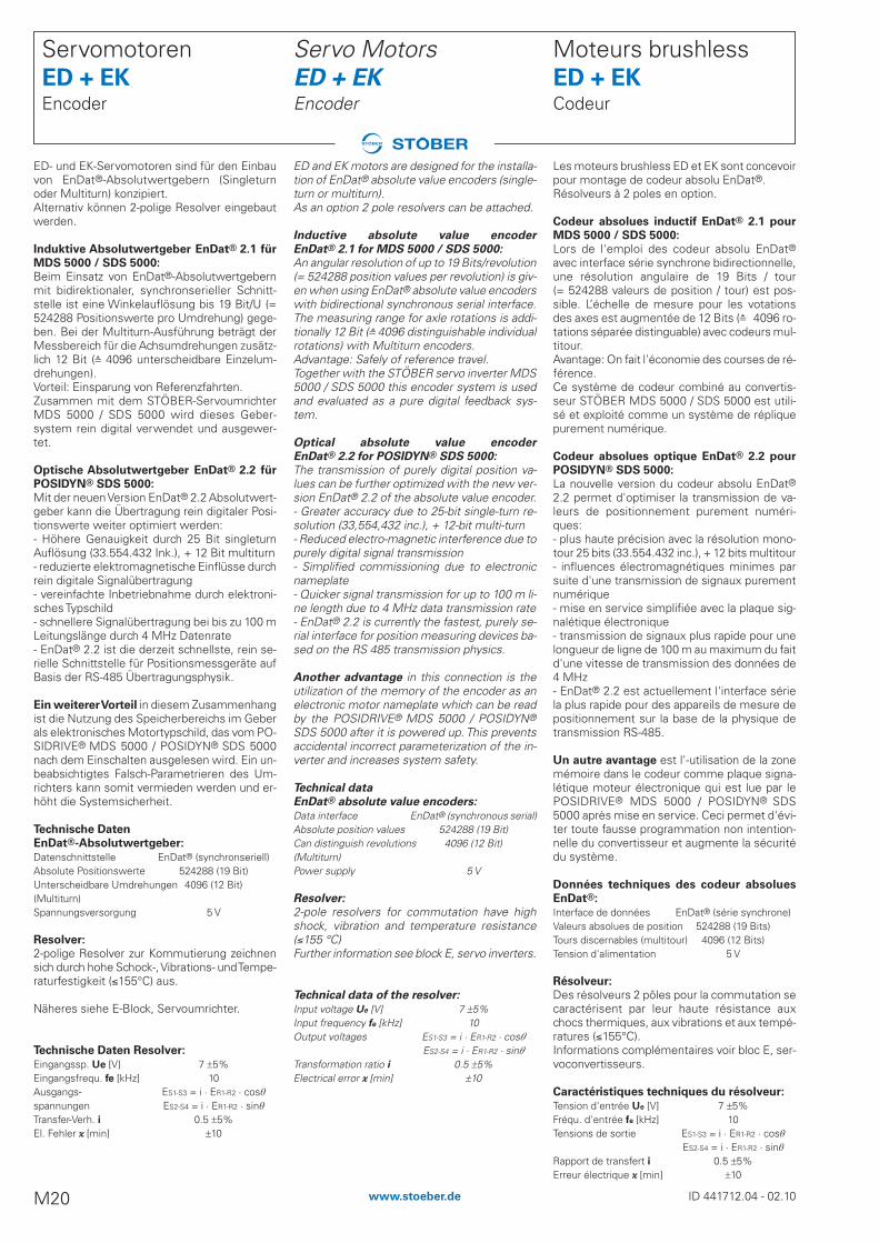
Les moteurs brushless ED et EK sont concevoirpour montage de codeur absolu EnDat®. Résolveurs à 2 poles en option.
Codeur absolues inductif EnDat® 2.1 pour
MDS 5000 / SDS 5000:
Lors de l'emploi des codeur absolu EnDat®avec interface série synchrone bidirectionnelle,une résolution angulaire de 19 Bits / tour (= 524288 valeurs de position / tour) est pos-sible. L’échelle de mesure pour les votationsdes axes est augmentée de 12 Bits (å 4096 ro-tations séparée distinguable) avec codeurs mul-titour.Avantage: On fait l'économie des courses de ré-férence. Ce système de codeur combiné au convertis-seur STÖBER MDS 5000 / SDS 5000 est utili-sé et exploité comme un système de répliquepurement numérique.
Codeur absolues optique EnDat® 2.2 pour
POSIDYN® SDS 5000:
La nouvelle version du codeur absolu EnDat®2.2 permet d'optimiser la transmission de va-leurs de positionnement purement numéri-ques:- plus haute précision avec la résolution mono-tour 25 bits (33.554.432 inc.), + 12 bits multitour- influences électromagnétiques minimes parsuite d'une transmission de signaux purementnumérique - mise en service simplifiée avec la plaque sig-nalétique électronique - transmission de signaux plus rapide pour unelongueur de ligne de 100 m au maximum du faitd'une vitesse de transmission des données de4 MHz- EnDat® 2.2 est actuellement l'interface sériela plus rapide pour des appareils de mesure depositionnement sur la base de la physique detransmission RS-485.
Un autre avantage est l'-utilisation de la zonemémoire dans le codeur comme plaque signa-létique moteur électronique qui est lue par lePOSIDRIVE® MDS 5000 / POSIDYN® SDS5000 après mise en service. Ceci permet d'évi-ter toute fausse programmation non intention-nelle du convertisseur et augmente la sécuritédu système.
Données techniques des codeur absolues
EnDat®:
Interface de données EnDat® (série synchrone)Valeurs absolues de position 524288 (19 Bits)Tours discernables (multitour) 4096 (12 Bits)Tension d'alimentation 5 V
Résolveur:
Des résolveurs 2 pôles pour la commutation secaractérisent par leur haute résistance auxchocs thermiques, aux vibrations et aux tempé-ratures (£155°C).Informations complémentaires voir bloc E, ser-voconvertisseurs.
Caractéristiques techniques du résolveur:
Tension d'entrée Ue [V] 7 !5%Fréqu. d'entrée fe [kHz] 10Tensions de sortie ES1-S3 = i · ER1-R2 · cos�
ES2-S4 = i · ER1-R2 · sin�
Rapport de transfert i 0.5 !5%Erreur électrique �� [min] !10
Moteurs brushless ED + EKCodeur
ED and EK motors are designed for the installa-tion of EnDat® absolute value encoders (single-turn or multiturn). As an option 2 pole resolvers can be attached.
Inductive absolute value encoder
EnDat® 2.1 for MDS 5000 / SDS 5000:
An angular resolution of up to 19 Bits/revolution(= 524288 position values per revolution) is giv-en when using EnDat® absolute value encoderswith bidirectional synchronous serial interface.The measuring range for axle rotations is addi-tionally 12 Bit (å 4096 distinguishable individualrotations) with Multiturn encoders.Advantage: Safely of reference travel.Together with the STÖBER servo inverter MDS5000 / SDS 5000 this encoder system is usedand evaluated as a pure digital feedback sys-tem.
Optical absolute value encoder
EnDat® 2.2 for POSIDYN® SDS 5000:
The transmission of purely digital position va-lues can be further optimized with the new ver-sion EnDat® 2.2 of the absolute value encoder. - Greater accuracy due to 25-bit single-turn re-solution (33,554,432 inc.), + 12-bit multi-turn- Reduced electro-magnetic interference due topurely digital signal transmission- Simplified commissioning due to electronicnameplate - Quicker signal transmission for up to 100 m li-ne length due to 4 MHz data transmission rate- EnDat® 2.2 is currently the fastest, purely se-rial interface for position measuring devices ba-sed on the RS 485 transmission physics.
Another advantage in this connection is theutilization of the memory of the encoder as anelectronic motor nameplate which can be readby the POSIDRIVE® MDS 5000 / POSIDYN®
SDS 5000 after it is powered up. This preventsaccidental incorrect parameterization of the in-verter and increases system safety.
Technical data
EnDat® absolute value encoders:
Data interface EnDat® (synchronous serial)Absolute position values 524288 (19 Bit)Can distinguish revolutions 4096 (12 Bit)(Multiturn)Power supply 5 V
Resolver:
2-pole resolvers for commutation have highshock, vibration and temperature resistance(£155 °C)Further information see block E, servo inverters.
Technical data of the resolver:
Input voltage Ue [V] 7 !5%Input frequency fe [kHz] 10Output voltages ES1-S3 = i · ER1-R2 · cos�
ES2-S4 = i · ER1-R2 · sin�
Transformation ratio i 0.5 !5%Electrical error �� [min] !10
Servo Motors ED + EKEncoder
ED- und EK-Servomotoren sind für den Einbauvon EnDat®-Absolutwertgebern (Singleturnoder Multiturn) konzipiert. Alternativ können 2-polige Resolver eingebautwerden.
Induktive Absolutwertgeber EnDat® 2.1 für
MDS 5000 / SDS 5000:
Beim Einsatz von EnDat®-Absolutwertgebernmit bidirektionaler, synchronserieller Schnitt-stelle ist eine Winkelauflösung bis 19 Bit/U (=524288 Positionswerte pro Umdrehung) gege-ben. Bei der Multiturn-Ausführung beträgt derMessbereich für die Achsumdrehungen zusätz-lich 12 Bit (å 4096 unterscheidbare Einzelum-drehungen).Vorteil: Einsparung von Referenzfahrten.Zusammen mit dem STÖBER-ServoumrichterMDS 5000 / SDS 5000 wird dieses Geber-system rein digital verwendet und ausgewer-tet.
Optische Absolutwertgeber EnDat® 2.2 für
POSIDYN® SDS 5000:
Mit der neuen Version EnDat® 2.2 Absolutwert-geber kann die Übertragung rein digitaler Posi-tionswerte weiter optimiert werden:- Höhere Genauigkeit durch 25 Bit singleturnAuflösung (33.554.432 Ink.), + 12 Bit multiturn- reduzierte elektromagnetische Einflüsse durchrein digitale Signalübertragung - vereinfachte Inbetriebnahme durch elektroni-sches Typschild - schnellere Signalübertragung bei bis zu 100 mLeitungslänge durch 4 MHz Datenrate- EnDat® 2.2 ist die derzeit schnellste, rein se-rielle Schnittstelle für Positionsmessgeräte aufBasis der RS-485 Übertragungsphysik.
Ein weiterer Vorteil in diesem Zusammenhangist die Nutzung des Speicherbereichs im Geberals elektronisches Motortypschild, das vom PO-SIDRIVE® MDS 5000 / POSIDYN® SDS 5000nach dem Einschalten ausgelesen wird. Ein un-beabsichtigtes Falsch-Parametrieren des Um-richters kann somit vermieden werden und er-höht die Systemsicherheit.
Technische Daten
EnDat®-Absolutwertgeber:
Datenschnittstelle EnDat® (synchronseriell)Absolute Positionswerte 524288 (19 Bit)Unterscheidbare Umdrehungen 4096 (12 Bit)(Multiturn)Spannungsversorgung 5 V
Resolver:
2-polige Resolver zur Kommutierung zeichnensich durch hohe Schock-, Vibrations- und Tempe-raturfestigkeit (£155°C) aus.
Näheres siehe E-Block, Servoumrichter.
Technische Daten Resolver:
Eingangssp. Ue [V] 7 !5%Eingangsfrequ. fe [kHz] 10Ausgangs- ES1-S3 = i · ER1-R2 · cos�
spannungen ES2-S4 = i · ER1-R2 · sin�
Transfer-Verh. i 0.5 !5%El. Fehler �� [min] !10
Servomotoren ED + EKEncoder
ID 441712.04 - 02.10M20 www.stoeber.de

Mot. FL UF // F IF PF QF GF mF dFmin
[V // Hz] [A] [W] [m3/h] [dBA] [kg] [mm]
ED4.. FL4 230+6%-10% // 0,07 10 59 41 1,4 2050/60 Hz
ED5../EK5..FL5 230+6%-10% // 0,10 14 160 45 1,9 2050/60 Hz
ED7../EK7.. FL7 230+6%-10% // 0,10 14 160 45 2,9 3050/60 Hz
ED8../EK8..FL8 230±10% // 0,20 26 420 54 5,0 3050/60 Hz
Elektrischer Anschluss Electrical connection Connexion électrique
La ventilation forcée* permet d’accroître les ca-ractéristiques des moteurs ED et EK STÖBER(cf. caractéristiques techniques aux pages M10- M11 et courbes caractéristiques aux pagesM12 - M16. Pour I’application, ceci signifie qu’ilest possible d’éviter d’opter pour un modèle su-périeur pour les conditions de charges et demasse données.Ce dispositif trouve également application lors-qu’une réduction des températures superfi-cielles de plus de 40°C (VDE 0530) a dû être réa-lisée en vue d’exploiter les caractéristiques no-minales du moteur.La ventilation forcée est disponible en option et,en raison de son exécution modulaire, peut éga-lement être rajoutée. Ainsi, il est possible deprocéder à des perfectionnements ultérieursde I’entraînement.Protection de ventilation forcée IP44.Un intervalle minimum dFmin jusqu’à l'entréed'air doit être respecté pour garantir un flux d’airsuffisant (cf. tableau).* pas pour le modèle ED2 et ED3
FL - Ventilation forcéeUF - Tension d’alimentation pour 50 / 60 HzIF - Courant pour 230 V, 50 HzPF - Puissance nominaleQF - Débit - plein airGF - Niveau acoustique dans la meilleure
zone de fonctionnementmF - Masse du kit complet de ventilation
forcéedFmin - Intervalle minimum jusqu’à l’entrée d’air
Moteurs brushless ED + EKVentilation forcée
Forced-air cooling* enables the performancedata for the STÖBER ED and EK motors to beincreased (see also Technical Data, pages M10to M11 and characteristics pages M12 to M16.With regard to the application this means thatdepending on the given load and moment of in-ertia conditions it may not be necessary tomove to the next higher size. Further applica-tions arise with the reduction of surface tem-peratures > 40°C (VDE 0530) necessary to uti-lize the motor data.The forced-air cooling is optional and also suit-able for retrofitting - thanks to the modular de-sign. This means that drives can also be opti-mized at a later stage.The enclosure type of the forced air cooling fanis IP44.To ensure a sufficient airstream the minimumgap dFmin to the air inlet acc. to the table belowis to be followed.* not with ED2 and ED3
FL - Forced-air cooling fanUF - Supply voltage for 50 / 60 HzIF - Current at 230 V, 50 HzPF - Rated powerQF - Delivery rate, outdoorsGF - Noise in optimum operating areamF - Weight of the complete forced-air
cooling setdFmin - Minimum gap to air inlet
Servo Motors ED + EKForced-air cooling
Durch die Fremdbelüftung* werden die Leis-tungsdaten der STÖBER ED- und EK-Motorenangehoben (siehe auch Technische Daten SeiteM10 - M11 und Kennlinien Seite M12 - M16). Fürdie Anwendung bedeutet dies, dass für vorge-gebene Last- u. Massenverhältnisse ggf. einBaugrößensprung vermieden werden kann.Weitere Anwendungen ergeben sich bei not-wendiger Reduzierung der Oberflächen-temperaturen > 40°C (VDE 0530) zur Ausnut-zung der Motornenndaten.Die Fremdbelüftung ist optional und durch denmodularen Aufbau auch zur Nachrüstung geeig-net, sodass Antriebsoptimierungen auch nach-träglich vorgenommen werden können.Die Schutzart des Fremdlüfters ist IP44.Um einen ausreichenden Luftstrom zu gewähr-leisten, ist ein Mindestabstand dFmin zum Luft-einlass nach Tabelle einzuhalten.* nicht für ED2 und ED3
FL - FremdlüfterUF - Anschlussspannung für 50 / 60 HzIF - Strom bei 230 V, 50 HzPF - NennleistungQF - Förderleistung-FreiluftGF - Geräusch im optimalen BetriebsbereichmF - Masse des kompletten Fremd-
lüftersatzesdFmin - Mindestabstand zum Lufteinlass
Servomotoren ED + EKFremdbelüftung
ID 441712.04 - 12.09 M21www.stoeber.de
MM
(2) OV
(4)
(1) 230Vfrei not usedlibre
1 = L1
2 = N
3 = frei not used libre
4 =
} 230V ± 10% 50/60Hz
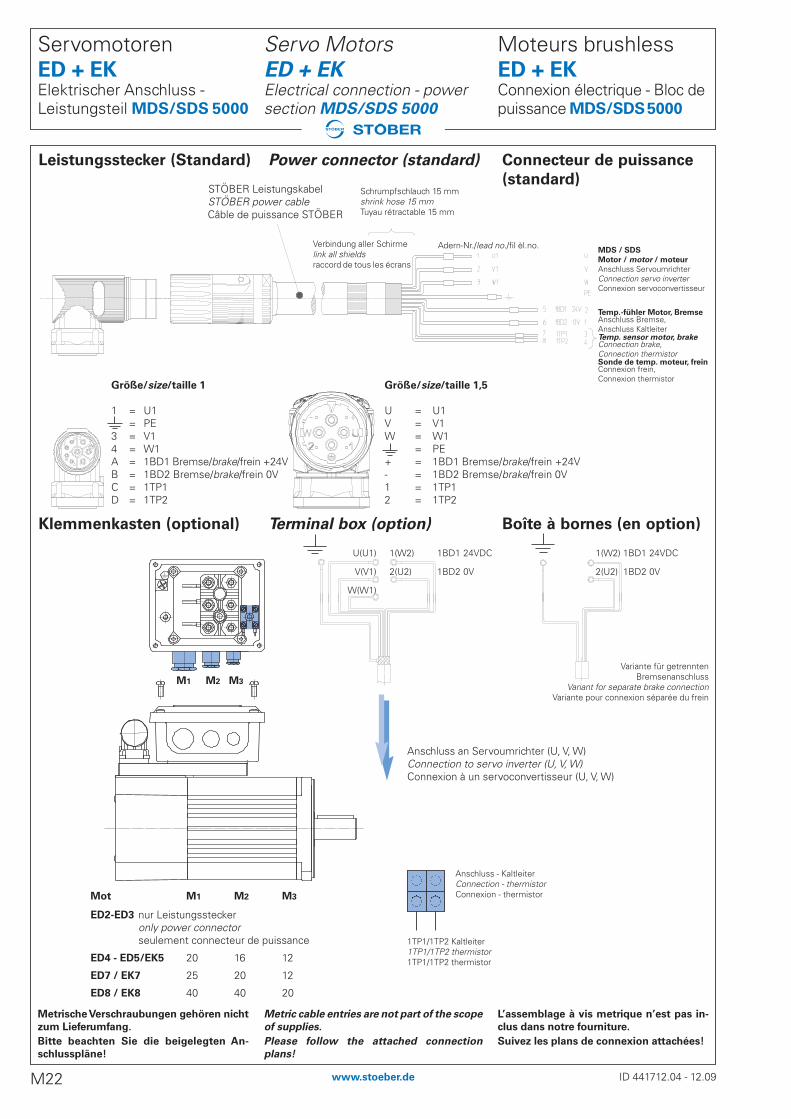
Variante für getrenntenBremsenanschluss
Variant for separate brake connectionVariante pour connexion séparée du frein
Anschluss an Servoumrichter (U, V, W)Connection to servo inverter (U, V, W)Connexion à un servoconvertisseur (U, V, W)
Anschluss - KaltleiterConnection - thermistorConnexion - thermistor
1TP1/1TP2 Kaltleiter1TP1/1TP2 thermistor1TP1/1TP2 thermistor
Mot M1 M2 M3
ED2-ED3 nur Leistungssteckeronly power connectorseulement connecteur de puissance
ED4 - ED5/EK5 20 16 12
ED7 / EK7 25 20 12
ED8 / EK8 40 40 20
MDS / SDS
Motor / motor / moteur
Anschluss ServoumrichterConnection servo inverterConnexion servoconvertisseur
Temp.-fühler Motor, BremseAnschluss Bremse, Anschluss Kaltleiter Temp. sensor motor, brakeConnection brake, Connection thermistor Sonde de temp. moteur, freinConnexion frein, Connexion thermistor
Schrumpfschlauch 15 mmshrink hose 15 mmTuyau rétractable 15 mm
Adern-Nr./lead no./fil èl.no.
Größe/size/taille 1
1 = U1= PE
3 = V14 = W1A = 1BD1 Bremse/brake/frein +24VB = 1BD2 Bremse/brake/frein 0VC = 1TP1D = 1TP2
Verbindung aller Schirmelink all shieldsraccord de tous les écrans
STÖBER LeistungskabelSTÖBER power cableCâble de puissance STÖBER
Leistungsstecker (Standard) Power connector (standard) Connecteur de puissance
(standard)
Klemmenkasten (optional) Terminal box (option) Boîte à bornes (en option)
Größe/size/taille 1,5
U = U1V = V1W = W1
= PE+ = 1BD1 Bremse/brake/frein +24V- = 1BD2 Bremse/brake/frein 0V1 = 1TP12 = 1TP2
L’assemblage à vis metrique n’est pas in-
clus dans notre fourniture.
Suivez les plans de connexion attachées!
Moteurs brushless ED + EKConnexion électrique - Bloc depuissance MDS/SDS5000
Metric cable entries are not part of the scope
of supplies.
Please follow the attached connection
plans!
Servo Motors ED + EKElectrical connection - power section MDS/SDS 5000
Metrische Verschraubungen gehören nicht
zum Lieferumfang.
Bitte beachten Sie die beigelegten An-
schlusspläne!
Servomotoren ED + EKElektrischer Anschluss - Leistungsteil MDS/SDS 5000
ID 441712.04 - 12.09M22 www.stoeber.de
M1 M2 M3
U(U1)
V(V1)
W(W1)
1(W2) 1BD1 24VDC
2(U2) 1BD2 0V
1(W2) 1BD1 24VDC
2(U2) 1BD2 0V
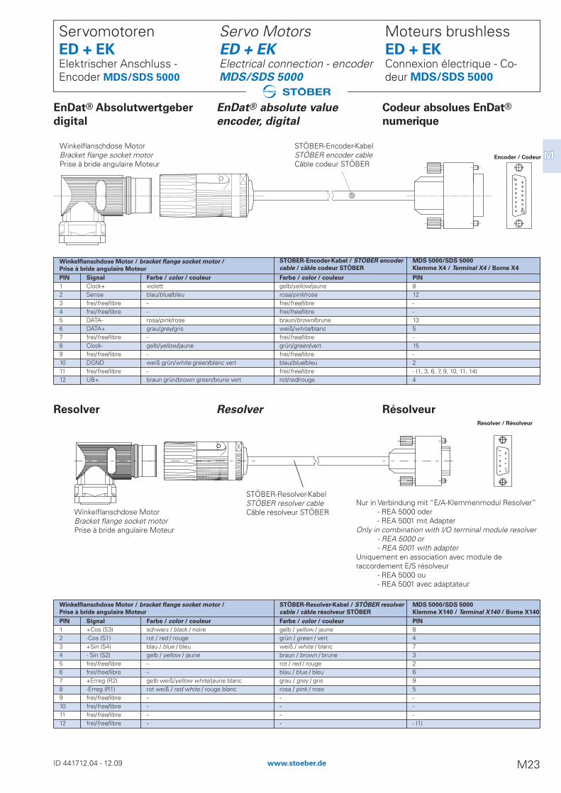
Winkelflanschdose Motor / bracket flange socket motor /
Prise à bride angulaire Moteur
STÖBER-Encoder-Kabel / STÖBER encoder
cable / câble codeur STÖBER
MDS 5000/SDS 5000
Klemme X4 / Terminal X4 / Borne X4
PIN Signal Farbe / color / couleur Farbe / color / couleur PIN
1 Clock+ violett gelb/yellow/jaune 82 Sense blau/blue/bleu rosa/pink/rose 123 frei/free/libre - frei/free/libre -4 frei/free/libre - frei/free/libre -5 DATA- rosa/pink/rose braun/brown/brune 136 DATA+ grau/grey/gris weiß/white/blanc 57 frei/free/libre - frei/free/libre -8 Clock- gelb/yellow/jaune grün/green/vert 159 frei/free/libre - frei/free/libre -10 DGND weiß grün/white green/blanc vert blau/blue/bleu 211 frei/free/libre - frei/free/libre - (1, 3, 6, 7, 9, 10, 11, 14)12 UB+ braun grün/brown green/brune vert rot/red/rouge 4
Winkelflanschdose Motor / bracket flange socket motor /
Prise à bride angulaire Moteur
STÖBER-Resolver-Kabel / STÖBER resolver
cable / câble résolveur STÖBER
MDS 5000/SDS 5000
Klemme X140 / Terminal X140 / Borne X140
PIN Signal Farbe / color / couleur Farbe / color / couleur PIN
1 +Cos (S3) schwarz / black / noire gelb / yellow / jaune 82 -Cos (S1) rot / red / rouge grün / green / vert 43 +Sin (S4) blau / blue / bleu weiß / white / blanc 74 - Sin (S2) gelb / yellow / jaune braun / brown / brune 35 frei/free/libre - rot / red / rouge 26 frei/free/libre - blau / blue / bleu 67 +Erreg (R2) gelb weiß/yellow white/jaune blanc grau / grey / gris 98 -Erreg (R1) rot weiß / red white / rouge blanc rosa / pink / rose 59 frei/free/libre - - -10 frei/free/libre - - -11 frei/free/libre - - -12 frei/free/libre - - - (1)
EnDat® Absolutwertgeber EnDat® absolute value Codeur absolues EnDat®
digital encoder, digital numerique
Winkelflanschdose MotorBracket flange socket motorPrise à bride angulaire Moteur
Encoder / Codeur
STÖBER-Encoder-KabelSTÖBER encoder cableCâble codeur STÖBER
STÖBER-Resolver-KabelSTÖBER resolver cableCâble résolveur STÖBERWinkelflanschdose Motor
Bracket flange socket motorPrise à bride angulaire Moteur
Nur in Verbindung mit “E/A-Klemmenmodul Resolver” - REA 5000 oder- REA 5001 mit Adapter
Only in combination with I/O terminal module resolver - REA 5000 or- REA 5001 with adapter
Uniquement en association avec module de raccordement E/S résolveur
- REA 5000 ou- REA 5001 avec adaptateur
Resolver / Résolveur
Resolver Resolver Résolveur
Moteurs brushless ED + EKConnexion électrique - Co-deur MDS/SDS 5000
Servo Motors ED + EKElectrical connection - encoderMDS/SDS 5000
Servomotoren ED + EKElektrischer Anschluss - Encoder MDS/SDS 5000
ID 441712.04 - 12.09 M23www.stoeber.de
MM

Winkelflanschdose Motor / bracket flange socket motor /
Prise à bride angulaire Moteur
STÖBER-Encoder-Kabel / STÖBER encoder
cable / câble codeur STÖBER
MDS 5000/SDS 5000
Klemme X140 / Terminal X140 / Borne X140
PIN Signal Farbe / color / couleur Farbe / color / couleur PIN
1 Up Sense blau/blue/bleu grün rot/green red/vert rouge 122 frei/free/libre - - -3 frei/free/libre - - -4 0V Sense weiß/white/blanc grün schwarz/green black/vert noir 105 - - - -6 - - - -7 Up braun grün/brown green/brune vert braun rot/brown red/brune rouge 48 Clock+ +422 violett/violet/violet weiß schwarz/white black/blanc noir 89 Clock- -422 gelb/yellow/jaune weiß gelb/white yellow/blanc jaune 1510 0V weiß grün/white green/blanc vert braun blau/brown blue/brune bleu 212 B+ blau schwarz/blue black/bleu noir rot/red/rouge 913 B- rot schwarz/red black/rouge noir orange/orange/orange 114 DATA+ +485 grau/grey/gris grau/grey/gris 515 A+ grün schwarz/green black/vert noir grün/green/vert 1116 A- gelb schwarz/yellow black/jaune noir gelb/yellow/jaune 317 DATA- -485 rosa/pink/rose blau/blue/bleu 13
EnDat® Absolutwertgeber EnDat® absolute value Codeur absolues EnDat®
Sin-Cos encoder Sin-Cos Sin-Cos
STÖBER-Encoder-KabelSTÖBER encoder cableCâble codeur STÖBER
Winkelflanschdose MotorBracket flange socket motorPrise à bride angulaire Moteur
Sin-Cos
Moteurs brushless ED + EKConnexion électrique - Co-deur MDS/SDS 5000
Servo Motors ED + EKElectrical connection - encoderMDS/SDS 5000
Servomotoren ED + EKElektrischer Anschluss - Encoder MDS/SDS 5000
ID 441712.04 - 12.09M24 www.stoeber.de
Nur in Verbindung mit “E/A-KlemmenmodulResolver” REA 5001 Only in combination with “I/O terminal mod-ule resolver” REA 5001Uniquement en association avec “module de raccordement E/S résolveur“ REA 5001
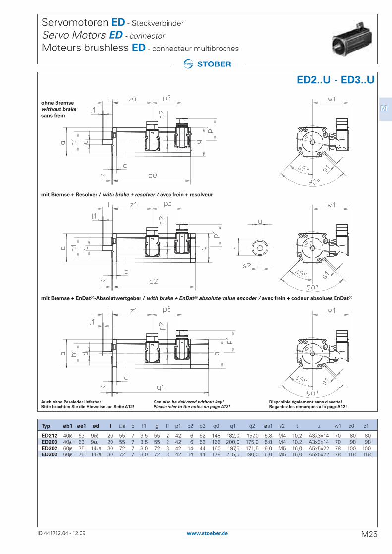
ohne Bremse
without brake
sans frein
mit Bremse + EnDat®-Absolutwertgeber / with brake + EnDat® absolute value encoder / avec frein + codeur absolues EnDat®
mit Bremse + Resolver / with brake + resolver / avec frein + resolveur
Disponible également sans clavette!
Regardez les remarques à la page A12!
Can also be delivered without key!
Please refer to the notes on page A12!
Auch ohne Passfeder lieferbar!
Bitte beachten Sie die Hinweise auf Seite A12!
Servomotoren ED - Steckverbinder
Servo Motors ED - connector
Moteurs brushless ED - connecteur multibroches
ID 441712.04 - 12.09 M25www.stoeber.de
MM
ED2..U - ED3..U
Typ øb1 øe1 ød l ±a c f1 g l1 p1 p2 p3 q0 q1 q2 øs1 s2 t u w1 z0 z1
ED212 40j6 63 9k6 20 55 7 3,5 55 2 42 6 52 148 182,0 157,0 5,8 M4 10,2 A3x3x14 70 80 80ED203 40j6 63 9k6 20 55 7 3,5 55 2 42 6 52 166 200,0 175,0 5,8 M4 10,2 A3x3x14 70 98 98ED302 60j6 75 14k6 30 72 7 3,0 72 3 42 14 44 160 197,5 171,5 6,0 M5 16,0 A5x5x22 78 100 100ED303 60j6 75 14k6 30 72 7 3,0 72 3 42 14 44 178 215,5 190,0 6,0 M5 16,0 A5x5x22 78 118 118

Servomotoren ED - Steckverbinder
Servo Motors ED - connector
Moteurs brushless ED - connecteur multibroches
ohne Bremse
without brake
sans frein
mit Bremse
with brake
avec frein
Disponible également sans clavette!
Regardez les remarques à la page A12!
* ED706 KE = 100
Can also be delivered without key!
Please refer to the notes on page A12!
* ED706 KE = 100
Auch ohne Passfeder lieferbar!
Bitte beachten Sie die Hinweise auf Seite A12!
* ED706 KE = 100
ID 441712.04 - 05.10M26 www.stoeber.de
Typ øb1 øe1 ød l ±a c f1 g l1 p1 p2 p3 p4 q0 q1 øs1 s2 t u w1 z0 z1
ED401 95j6 115 14k6 30 98 10 3,5 98 3 42 31,0 35,0 35,0 148 194,0 9,0 M5 16 A5x5x22 91,0 95 141ED402 95j6 115 19k6 40 98 10 3,5 98 3 42 31,0 35,0 35,0 183 229,0 9,0 M6 22 A6x6x32 91,0 130 176ED403 95j6 115 19k6 40 98 10 3,5 98 3 42 31,0 35,0 35,0 218 264,0 9,0 M6 22 A6x6x32 91,0 165 211ED503 110j6 130 24k6 50 115 11 3,5 115 3 42 32,0 35,0 35,0 220 271,0 9,0 M8 27 A8x7x40 100,0 163 214ED505 110j6 130 24k6 50 115 11 3,5 115 3 42 32,0 35,0 35,0 290 341,0 9,0 M8 27 A8x7x40 100,0 233 284ED704 130j6 165 24k6 50 145 11 3,5 145 3 42 40,0 35,0 35,0 279 342,5 11,0 M8 27 A8x7x40 115,0 222 286ED706 130j6 165 32k6 58 145 11 3,5 145 3 42 40,0 35,0 35,0 349 412,5 11,0 M12 35 A10x8x50 115,0 292 356ED706* 130j6 165 32k6 58 145 11 3,5 145 3 71 40,0 29,5 35,0 349 412,5 11,0 M12 35 A10x8x50 137,0 298 356ED806 180j6 215 38k6 80 190 18 4,0 190 5 71 56,0 57,0 126,0 383 452,0 13,5 M12 41 A10x8x70 157,5 307 307ED808 180j6 215 38k6 80 190 18 4,0 190 5 71 56,0 57,0 126,0 453 522,0 13,5 M12 41 A10x8x70 157,5 377 377
ED4..U - ED8..U

Servomotoren ED - Klemmenkasten
Servo Motors ED - terminal box
Moteurs brushless ED - boîte à bornes
ohne Bremse
without brake
sans frein
mit Bremse
with brake
avec frein
Disponible également sans clavette!
Regardez les remarques à la page A12!
Can also be delivered without key!
Please refer to the notes on page A12!
Auch ohne Passfeder lieferbar!
Bitte beachten Sie die Hinweise auf Seite A12!
ID 441712.04 - 12.09 M27www.stoeber.de
MM
ED4..U - ED8..U
Typ øb1 øe1 ød l ±a c f1 g l1 q0 q1 øs1 s2 t u w x1 y1 z2 z3 z4
ED401 95j6 115 14k6 30 98 10 3,5 98 3 148 194,0 9,0 M5 16,0 A5x5x22 118,0 109 106 18 60 106ED402 95j6 115 19k6 40 98 10 3,5 98 3 183 229,0 9,0 M6 21,5 A6x6x32 118,0 109 106 18 95 141ED403 95j6 115 19k6 40 98 10 3,5 98 3 218 264,0 9,0 M6 21,5 A6x6x32 118,0 109 106 18 130 176ED503 110j6 130 24k6 50 115 11 3,5 115 3 220 271,0 9,0 M8 27,0 A8x7x40 127,0 109 106 22 128 179ED505 110j6 130 24k6 50 115 11 3,5 115 3 290 341,0 9,0 M8 27,0 A8x7x40 127,0 109 106 22 198 249ED704 130j6 165 24k6 50 145 11 3,5 145 3 279 342,5 11,0 M8 27,0 A8x7x40 147,0 119 114 22 183 247ED706 130j6 165 32k6 58 145 11 3,5 145 3 349 412,5 11,0 M12 35,0 A10x8x50 147,0 119 114 22 253 317ED806 180j6 215 38k6 80 190 18 4,0 190 5 383 452,0 13,5 M12 41,0 A10x8x70 198,0 165 192 19 267 267ED808 180j6 215 38k6 80 190 18 4,0 190 5 453 522,0 13,5 M12 41,0 A10x8x70 198,0 165 192 19 337 337

Servomotoren ED - fremdbelüftet
Servo Motors ED - forced cooled
Moteurs brushless ED - ventilation forcée
Steckverbinder
ohne Bremse
Connector
without brake
Connecteur multi-
broches sans frein
Klemmenkasten
ohne Bremse
Terminal box
without brake
Boîte à bornes
sans frein
Steckverbinder
mit Bremse
Connector with brake
Connecteur multi-
broches avec frein
Disponible également sans clavette!
Regardez les remarques à la page A12!
Can also be delivered without key!
Please refer to the notes on page A12!
Auch ohne Passfeder lieferbar!
Bitte beachten Sie die Hinweise auf Seite A12!
* ED706, ED806 KE = 100 / ED808 KE = 110* ED706, ED806 KE = 100 / ED808 KE = 110* ED706, ED806 KE = 100 / ED808 KE = 110
ID 441712.04 - 12.09M28 www.stoeber.de
ED4..B - ED8..B
Typ øb1 øe1 ød l ±a c f1 g1 l1 p1 p2 q3 q4 øs1 s2 t u w w1 w2 x1 y1 z0 z1 z3 z5 z6
ED401 95j6 115 14k6 30 98 10 3,5 117 3 42 31,0 200 246 9,0 M5 16,0 A5x5x22 118,0 91,0 111 109 106 95 141 60 25 70ED402 95j6 115 19k6 40 98 10 3,5 117 3 42 31,0 235 281 9,0 M6 21,5 A6x6x32 118,0 91,0 111 109 106 130 176 95 25 70ED403 95j6 115 19k6 40 98 10 3,5 117 3 42 31,0 270 316 9,0 M6 21,5 A6x6x32 118,0 91,0 111 109 106 165 211 130 25 70ED503 110j6 130 24k6 50 115 11 3,5 135 3 42 32,0 290 341 9,0 M8 27,0 A8x7x40 127,0 100,0 120 109 106 163 214 128 25 92ED505 110j6 130 24k6 50 115 11 3,5 135 3 42 32,0 360 411 9,0 M8 27,0 A8x7x40 127,0 100,0 120 109 106 233 284 198 25 92ED704 130j6 165 24k6 50 145 11 3,5 164 3 42 40,0 385 449 11,0 M8 27,0 A8x7x40 147,0 115,0 134 119 114 222 286 183 40 128ED706 130j6 165 32k6 58 145 11 3,5 164 3 42 40,0 455 519 11,0 M12 35,0 A10x8x50 147,0 115,0 134 119 114 292 356 253 40 128ED706* 130j6 165 32k6 58 145 11 3,5 164 3 71 40,0 455 519 11,0 M12 35,0 A10x8x50 147,0 137,0 134 119 114 292 356 253 40 128ED806 180j6 215 38k6 80 190 18 4,0 215 5 71 56,0 499 568 13,5 M12 41,0 A10x8x70 198,0 157,5 160 165 192 307 307 267 40 135ED806* 180j6 215 38k6 80 190 18 4,0 215 5 66 54,5 499 568 13,5 M12 41,0 A10x8x70 198,0 168,0 160 165 192 292 295 267 40 135ED808 180j6 215 38k6 80 190 18 4,0 215 5 71 56,0 569 638 13,5 M12 41,0 A10x8x70 198,0 157,5 160 165 192 377 377 337 40 135ED808* 180j6 215 38k6 80 190 18 4,0 215 5 66 54,5 569 638 13,5 M12 41,0 A10x8x70 198,0 168,0 160 165 192 362 365 337 40 135
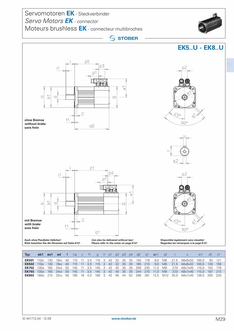
Servomotoren EK - Steckverbinder
Servo Motors EK - connector
Moteurs brushless EK - connecteur multibroches
ohne Bremse
without brake
sans frein
mit Bremse
with brake
avec frein
Disponible également sans clavette!
Regardez les remarques à la page A12!
Can also be delivered without key!
Please refer to the notes on page A12!
Auch ohne Passfeder lieferbar!
Bitte beachten Sie die Hinweise auf Seite A12!
ID 441712.04 - 12.09 M29www.stoeber.de
MM
Typ øb1 øe1 ød l ±a c f1 g l1 p1 p2 p3 p4 q0 q1 øs1 s2 t u w1 z0 z1
EK501 110j6 130 19k6 40 115 11 3,5 115 3 42 32 35 35 150 178 9,0 M6 21,5 A6x6x32 100,0 93 121EK502 110j6 130 19k6 40 115 11 3,5 115 3 42 32 35 35 185 213 9,0 M6 21,5 A6x6x32 100,0 128 156EK702 130j6 165 24k6 50 145 11 3,5 145 3 42 40 35 35 209 235 11,0 M8 27,0 A8x7x40 115,0 152 178EK703 130j6 165 24k6 50 145 11 3,5 145 3 42 40 35 35 244 270 11,0 M8 27,0 A8x7x40 115,0 187 213EK803 180j6 215 32k6 58 190 18 4,0 190 3 42 56 44 62 268 301 13,5 M12 35,0 A8x7x40 136,5 205 220
EK5..U - EK8..U

Servomotoren EK - Klemmenkasten
Servo Motors EK - terminal box
Moteurs brushless EK - boîte à bornes
ohne Bremse
without brake
sans frein
mit Bremse
with brake
avec frein
Disponible également sans clavette!
Regardez les remarques à la page A12!
Can also be delivered without key!
Please refer to the notes on page A12!
Auch ohne Passfeder lieferbar!
Bitte beachten Sie die Hinweise auf Seite A12!
ID 441712.04 - 12.09M30 www.stoeber.de
EK5..U - EK8..U
Typ øb1 øe1 ød l ±a c f1 g l1 q0 q1 øs1 s2 t u w x1 y1 z2 z3 z4
EK501 110j6 130 19k6 40 115 11 3,5 115 3 150 178 9,0 M6 21,5 A6x6x32 127,0 109 106 22 58 86EK502 110j6 130 19k6 40 115 11 3,5 115 3 185 213 9,0 M6 21,5 A6x6x32 127,0 109 106 22 93 121EK702 130j6 165 24k6 50 145 11 3,5 145 3 209 235 11,0 M8 27,0 A8x7x40 147,0 119 114 22 113 139EK703 130j6 165 24k6 50 145 11 3,5 145 3 244 270 11,0 M8 27,0 A8x7x40 147,0 119 114 22 148 174EK803 180j6 215 32k6 58 190 18 4,0 190 3 268 301 13,5 M12 35,0 A8x7x40 167,5 165 192 19 152 168
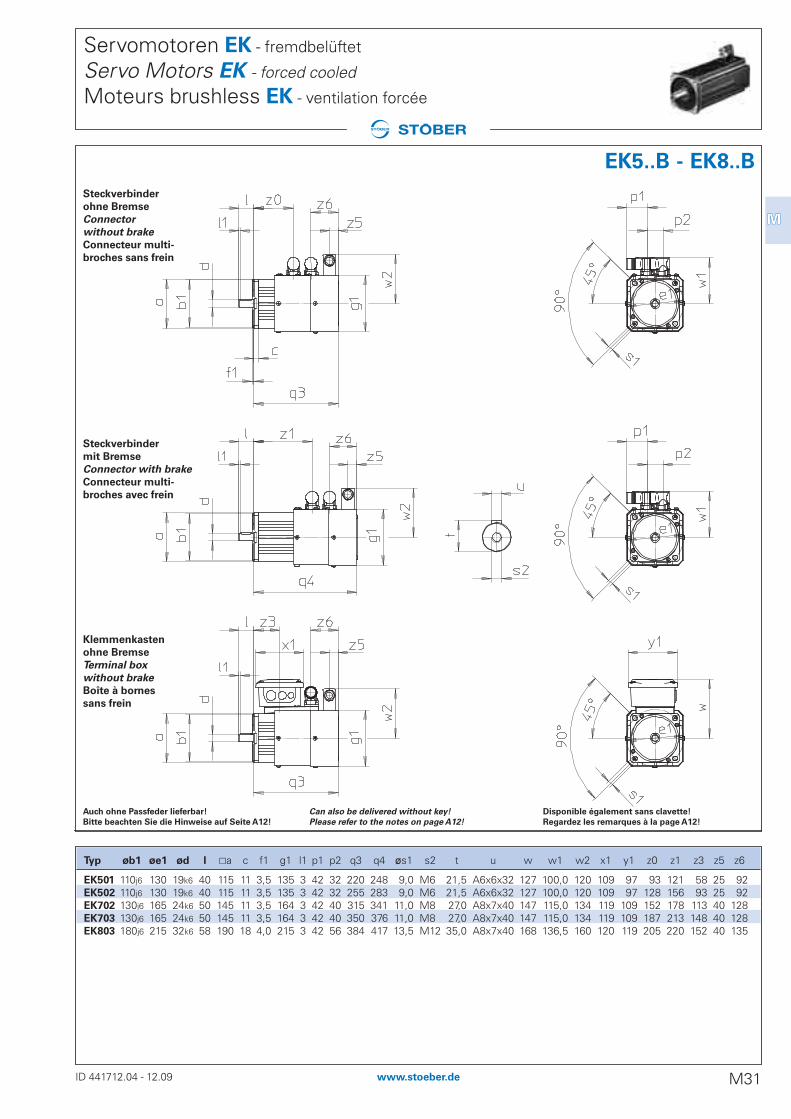
Servomotoren EK - fremdbelüftet
Servo Motors EK - forced cooled
Moteurs brushless EK - ventilation forcée
Steckverbinder
ohne Bremse
Connector
without brake
Connecteur multi-
broches sans frein
Klemmenkasten
ohne Bremse
Terminal box
without brake
Boîte à bornes
sans frein
Steckverbinder
mit Bremse
Connector with brake
Connecteur multi-
broches avec frein
Disponible également sans clavette!
Regardez les remarques à la page A12!
Can also be delivered without key!
Please refer to the notes on page A12!
Auch ohne Passfeder lieferbar!
Bitte beachten Sie die Hinweise auf Seite A12!
ID 441712.04 - 12.09 M31www.stoeber.de
MM
EK5..B - EK8..B
Typ øb1 øe1 ød l ±a c f1 g1 l1 p1 p2 q3 q4 øs1 s2 t u w w1 w2 x1 y1 z0 z1 z3 z5 z6
EK501 110j6 130 19k6 40 115 11 3,5 135 3 42 32 220 248 9,0 M6 21,5 A6x6x32 127 100,0 120 109 97 93 121 58 25 92EK502 110j6 130 19k6 40 115 11 3,5 135 3 42 32 255 283 9,0 M6 21,5 A6x6x32 127 100,0 120 109 97 128 156 93 25 92EK702 130j6 165 24k6 50 145 11 3,5 164 3 42 40 315 341 11,0 M8 27,0 A8x7x40 147 115,0 134 119 109 152 178 113 40 128EK703 130j6 165 24k6 50 145 11 3,5 164 3 42 40 350 376 11,0 M8 27,0 A8x7x40 147 115,0 134 119 109 187 213 148 40 128EK803 180j6 215 32k6 58 190 18 4,0 215 3 42 56 384 417 13,5 M12 35,0 A8x7x40 168 136,5 160 120 119 205 220 152 40 135