
REST BASED INTERNET OF THINGS SERVICES AND APPLICATIONS IN...
318
REST - BASED I NTERNET OF THINGS - SERVICES AND APPLICATIONS IN A SEMANTICS - AWARE ENTERPRISE CONTEXT Inauguraldissertation der Philosophisch-naturwissenschaftlichen Fakult¨ at der Universit¨ at Bern vorgelegt von Matthias Thoma von Deutschland Leiter der Arbeit: Professor Dr. Torsten Braun Institut f ¨ ur Informatik
Transcript of REST BASED INTERNET OF THINGS SERVICES AND APPLICATIONS IN...

REST-BASED INTERNET OF
THINGS-SERVICES AND APPLICATIONS IN
A SEMANTICS-AWARE ENTERPRISE
CONTEXT
Inauguraldissertationder Philosophisch-naturwissenschaftlichen Fakultat
der Universitat Bern
vorgelegt von
Matthias Thoma
von Deutschland
Leiter der Arbeit:Professor Dr. Torsten Braun
Institut fur Informatik
Von der Philosophisch-naturwissenschaftlichen Fakultat angenommen.
Der Dekan:Bern, 21.12.2016 Prof. Dr. Gilberto Colangelo

iv
Abstract
The Internet of Things (IoT) is the vision of a global infrastructure of networkedphysical objects. In order to use IoT in a semantics-aware enterprise there are somechallenges: IoT-devices should integrate into enterprises as seamlessly as possible, bothat a modeling level and at a technology level. At the modeling level, enterprise systemsare often customized by non-software experts. In addition, more and more systems areapplying machine-learning technologies. Both human modeling and machine reasoningneed a precise semantic description of the entities they work with and their meaning. Atthe technology level, enterprise systems traditionally use a different protocol stack thanIoT-devices. Neither these traditional enterprise protocols nor the IoT-protocols aresemantics-aware. Furthermore, IoT-devices have properties that are typically unknownto enterprise information systems, such as their limited energy and consequently theirmaintenance needs (i.e. swapping batteries). Keeping this total cost of ownership lowis one of the primary goals of IoT-operators.
This thesis contributes to enterprise integration and semantic-aware integrationby developing and evaluating two different approaches: a top-down approach and abottom-up approach. The top-down approach scales down the existing OData enter-prise protocol to very constrained IoT-devices. The bottom-up approach semanticallyenriches existing protocols. It consists of a service description language called LinkedUSDL for IoT, which allows to semantically describe services from a very high abstrac-tion level, down to their technical realization. In order to utilize those approaches inan enterprise, we propose an architecture and abstractions that enable the integrationof BPMN tools, semantic services, and constrained IoT-devices. We also investigatedsome reasons for the reluctance of developers to apply semantics, a behavior coinedsemaphobia in previous research. We evaluated our approach with an architectureevaluation method and through several experiments. The experiments were done on anexperimental platform called Mote Runner on the following two hardware platforms:MEMSIC IRIS and Waspmote Pro.
We propose an application-layer based framework for reducing the energy consump-tion by putting nodes to sleep (sleepy nodes). Sleepy Nodes were implemented andevaluated on the Mote Runner platform. We introduce a monitoring framework basedupon high-level information that utilizes sleepy nodes to increase the network lifetime.As part of the monitoring framework, we present three different scheduling strategies:A simple first fit, an exhaustive strategy, and a strategy called dynamic partitioning.Dynamic partitioning is based on the observation that it is possible to combine measure-ments under certain circumstances. We were able to show that dynamic partitioningperforms significantly better than first fit and only slightly worse than the exhaustivestrategy.
v

vi
Acknowledgments
This PhD thesis is based on work performed during my employment as a PhD-studentat the Institute of Computer Science of the University of Bern, Switzerland and duringmy employment as a researcher at SAP (Switzerland) Inc.
The research conducted in this thesis was partially supported by the EuropeanUnion under grant IoT-A and grant FI-WARE. Over the years, I was fortunate to meetand work with many intelligent people who contributed to my thesis – some maybewithout even being aware of it through all the fruitful discussions we had.
I would wish to thank everybody who provided me with support, ideas, understand-ing, discussion, and encouragement during the course of my PhD thesis. First, I expressmy gratitude to Prof. Dr. Torsten Braun, head of the Communication and DistributedSystems group (CDS), who supervised and encouraged my work. He offered me thechance to become an external PhD-student working with his research group and healways tried to get me on the right track. I would also like to thank Prof. Dr. StefanFischer for accepting to read this work and Prof. Dr. Paolo Favaro, who was willing tobe co-examiner. Furthermore, I thank the SAP research community for the challengingwork environment.
Many thanks go to my colleagues at SAP for being a great team. In particular, Iwish to thank (in alphabetical order): Alexandru-Florian Antonescu, Stephan Haller,Carsten Magerkurth, Sonja Meyer, Basil Hess and Klaus Sperner. I would also liketo thank the team at the University of Bern for the time with them, their feedback andgiving me a different perspective on my work. In particular Thomas Staub, MarkusAnwander, Gerald Wagenknecht, Desislava Dimitrova, Carlos Anastasiades, Zan Li,Denis Rosario, Andre Gomes, Jonnahtan Saltarin, Imad Aad, Dima Mansour, AlmerimaJamakovic-Kapic, Eryk Schiller, Andreea Hossmann and Eirina Bourtsoulatze. Specialthanks go to Daniela Schroth for her support in the administrative tasks and reserving aparking spot for us.
Furthermore, I must explicitly thank two collaborators: Marcus Oestreicher fromIBM Research and Stefan Meissner from the University of Surrey. Marcus provided mewith all support around the Mote Runner platform one could wish for. Stefan introducedme to ideas in the semantic services community and helped me write several papers.
I would also like to thank all the students, who contributed to this thesis in one wayor another. In particular, thanks go out to our interns at SAP – namely TriantafyllosAfouras, Michael Gede, Theofilos Kakantousis, Theano Mintsi, Georgious Tentes, andMartin Zabel.
vii

viii

Contents
Contents ix
List of Figures xv
List of Tables xix
I Introduction and Related Work 1
1 Introduction 31.1 Internet of Things . . . . . . . . . . . . . . . . . . . . . . . . . . . . 31.2 Motivation and Problem Statement . . . . . . . . . . . . . . . . . . . 51.3 Complexity of IoT-solutions and Semantics-aware Enterprise Integration 61.4 Internet of Things Stack . . . . . . . . . . . . . . . . . . . . . . . . . 91.5 Application-layer Energy Saving . . . . . . . . . . . . . . . . . . . . 121.6 Contributions . . . . . . . . . . . . . . . . . . . . . . . . . . . . . . 131.7 Outline . . . . . . . . . . . . . . . . . . . . . . . . . . . . . . . . . 15
2 Foundations and Related Work 172.1 Hardware . . . . . . . . . . . . . . . . . . . . . . . . . . . . . . . . 17
2.1.1 Overview . . . . . . . . . . . . . . . . . . . . . . . . . . . . 172.1.2 IRIS . . . . . . . . . . . . . . . . . . . . . . . . . . . . . . . 192.1.3 Waspmote Pro . . . . . . . . . . . . . . . . . . . . . . . . . 21
2.2 Mote Runner System . . . . . . . . . . . . . . . . . . . . . . . . . . 222.2.1 Overview . . . . . . . . . . . . . . . . . . . . . . . . . . . . 222.2.2 Toolchain . . . . . . . . . . . . . . . . . . . . . . . . . . . . 242.2.3 Version History . . . . . . . . . . . . . . . . . . . . . . . . . 262.2.4 Hardware . . . . . . . . . . . . . . . . . . . . . . . . . . . . 27
2.3 Protocols . . . . . . . . . . . . . . . . . . . . . . . . . . . . . . . . 272.3.1 802.15.4 . . . . . . . . . . . . . . . . . . . . . . . . . . . . 282.3.2 6LoWPAN . . . . . . . . . . . . . . . . . . . . . . . . . . . 292.3.3 MRv6 . . . . . . . . . . . . . . . . . . . . . . . . . . . . . . 30
2.4 Representational State Transfer . . . . . . . . . . . . . . . . . . . . . 342.5 Constrained Application Protocol . . . . . . . . . . . . . . . . . . . . 36
ix

2.6 OData . . . . . . . . . . . . . . . . . . . . . . . . . . . . . . . . . . 452.6.1 Overview . . . . . . . . . . . . . . . . . . . . . . . . . . . . 452.6.2 Version History . . . . . . . . . . . . . . . . . . . . . . . . . 462.6.3 Services, Resources and Data Model . . . . . . . . . . . . . . 462.6.4 Data Representation . . . . . . . . . . . . . . . . . . . . . . 48
2.7 Modelling of Vocabularies and Ontologies . . . . . . . . . . . . . . . 492.7.1 Resource Description Framework . . . . . . . . . . . . . . . 492.7.2 Turtle Notation . . . . . . . . . . . . . . . . . . . . . . . . . 512.7.3 Web Ontology Language . . . . . . . . . . . . . . . . . . . . 522.7.4 Properties . . . . . . . . . . . . . . . . . . . . . . . . . . . . 542.7.5 SPARQL . . . . . . . . . . . . . . . . . . . . . . . . . . . . 54
2.8 Data Reduction . . . . . . . . . . . . . . . . . . . . . . . . . . . . . 542.9 Sleepy Nodes . . . . . . . . . . . . . . . . . . . . . . . . . . . . . . 572.10 Services . . . . . . . . . . . . . . . . . . . . . . . . . . . . . . . . . 58
2.10.1 Legacy Enterprise Services . . . . . . . . . . . . . . . . . . . 582.10.2 SOAP-based Services . . . . . . . . . . . . . . . . . . . . . 592.10.3 REST WEB APIs . . . . . . . . . . . . . . . . . . . . . . . . 60
2.11 Service Descriptions . . . . . . . . . . . . . . . . . . . . . . . . . . 612.11.1 Semantic Annotations for WSDL and XML Schema . . . . . 612.11.2 OWL-S . . . . . . . . . . . . . . . . . . . . . . . . . . . . . 622.11.3 Web Service Modeling Ontology . . . . . . . . . . . . . . . . 622.11.4 Web Application Description Language and the Semantic Bridge
for Web Services . . . . . . . . . . . . . . . . . . . . . . . . 632.11.5 Semantic Annotations for REST . . . . . . . . . . . . . . . . 632.11.6 HTML for RESTful Services . . . . . . . . . . . . . . . . . . 632.11.7 MicroWSMO . . . . . . . . . . . . . . . . . . . . . . . . . . 642.11.8 Resource Linking Language . . . . . . . . . . . . . . . . . . 642.11.9 RESTdesc . . . . . . . . . . . . . . . . . . . . . . . . . . . . 642.11.10 Semantic RESTful Data Services . . . . . . . . . . . . . . . 64
2.12 Integration: Internet of Things and Web of Things . . . . . . . . . . . 652.12.1 Web-Service based Enterprise Integration of WSNs . . . . . . 652.12.2 Web of Things Integration . . . . . . . . . . . . . . . . . . . 662.12.3 Process-based Integration . . . . . . . . . . . . . . . . . . . 66
2.13 Summary . . . . . . . . . . . . . . . . . . . . . . . . . . . . . . . . 68
II Service Architecture for Embedding IoT-services into EnterpriseEnvironments 69
3 Services and the Internet of Things 713.1 Introduction . . . . . . . . . . . . . . . . . . . . . . . . . . . . . . . 713.2 Services . . . . . . . . . . . . . . . . . . . . . . . . . . . . . . . . . 723.3 Survey on the term ”Service” in IoT . . . . . . . . . . . . . . . . . . 72
x
3.4 Services and the Internet of Things-Architecture . . . . . . . . . . . . 743.5 Definition and Classification of IoT-Services . . . . . . . . . . . . . . 783.6 Conclusions . . . . . . . . . . . . . . . . . . . . . . . . . . . . . . . 80
4 Enterprise-embedded IoT-Services 814.1 Introduction . . . . . . . . . . . . . . . . . . . . . . . . . . . . . . . 814.2 Key Drivers . . . . . . . . . . . . . . . . . . . . . . . . . . . . . . . 824.3 Semantic Service Descriptions . . . . . . . . . . . . . . . . . . . . . 834.4 Linked Services . . . . . . . . . . . . . . . . . . . . . . . . . . . . . 844.5 Semantic Physical Business Entities . . . . . . . . . . . . . . . . . . 854.6 Enterprise Integration . . . . . . . . . . . . . . . . . . . . . . . . . . 86
4.6.1 Requirements . . . . . . . . . . . . . . . . . . . . . . . . . . 874.6.2 Application Scenario . . . . . . . . . . . . . . . . . . . . . . 88
4.7 Enterprise Integration Platform Architecture . . . . . . . . . . . . . . 904.8 Conclusions . . . . . . . . . . . . . . . . . . . . . . . . . . . . . . . 94
III Implementation, Service Descriptions and Protocols 95
5 Linked USDL for IoT 975.1 Introduction . . . . . . . . . . . . . . . . . . . . . . . . . . . . . . . 975.2 Design Principles . . . . . . . . . . . . . . . . . . . . . . . . . . . . 1015.3 Linked USDL . . . . . . . . . . . . . . . . . . . . . . . . . . . . . . 1025.4 IoT-specific Vocabularies . . . . . . . . . . . . . . . . . . . . . . . . 105
5.4.1 Vocabulary: Endpoint and Application-layer Support . . . . . 1055.4.2 Vocabulary: Event Support . . . . . . . . . . . . . . . . . . . 1085.4.3 Vocabulary: Quality of Information Support . . . . . . . . . . 1095.4.4 Vocabulary: REST Support . . . . . . . . . . . . . . . . . . . 111
5.5 Representations . . . . . . . . . . . . . . . . . . . . . . . . . . . . . 1135.6 Relationship to further Ontologies . . . . . . . . . . . . . . . . . . . 1155.7 Illustrating Example of a Sensor Service Modeled in Linked USDL4IoT1165.8 Conclusions . . . . . . . . . . . . . . . . . . . . . . . . . . . . . . . 118
6 CoAP and OData 1196.1 Introduction . . . . . . . . . . . . . . . . . . . . . . . . . . . . . . . 1196.2 CoAP . . . . . . . . . . . . . . . . . . . . . . . . . . . . . . . . . . 120
6.2.1 CoAP on a Reactive VM-based OS . . . . . . . . . . . . . . 1206.2.2 Implementation . . . . . . . . . . . . . . . . . . . . . . . . . 1216.2.3 Redirections . . . . . . . . . . . . . . . . . . . . . . . . . . 1236.2.4 Validation . . . . . . . . . . . . . . . . . . . . . . . . . . . . 1236.2.5 Embedded Java: Experiences and Lessons Learned . . . . . . 124
6.3 OData . . . . . . . . . . . . . . . . . . . . . . . . . . . . . . . . . . 1246.3.1 Introduction . . . . . . . . . . . . . . . . . . . . . . . . . . . 1256.3.2 OData on Wireless Sensor Motes . . . . . . . . . . . . . . . 126
xi

6.3.3 OData and Semantics . . . . . . . . . . . . . . . . . . . . . . 1296.4 Conclusions . . . . . . . . . . . . . . . . . . . . . . . . . . . . . . . 134
7 REST Sleepy Node Integration 1377.1 Introduction . . . . . . . . . . . . . . . . . . . . . . . . . . . . . . . 1387.2 REST API . . . . . . . . . . . . . . . . . . . . . . . . . . . . . . . . 1397.3 Integration of Sleepy Nodes into the Enterprise Integration Platform . 1407.4 Energy Model . . . . . . . . . . . . . . . . . . . . . . . . . . . . . . 142
7.4.1 Introduction . . . . . . . . . . . . . . . . . . . . . . . . . . . 1427.4.2 Energy Model . . . . . . . . . . . . . . . . . . . . . . . . . . 142
7.5 Implementation of Mid- and Longterm Sleeping in MRv6 . . . . . . . 1437.5.1 MRv6 Extensions for Sleepy Node Functionality . . . . . . . 1437.5.2 Clock-Drift Considerations . . . . . . . . . . . . . . . . . . . 145
7.6 Measurement Framework . . . . . . . . . . . . . . . . . . . . . . . . 1487.6.1 Problem Formulation . . . . . . . . . . . . . . . . . . . . . . 1487.6.2 Implementation of the Windowing-based Task Allocation Frame-
work . . . . . . . . . . . . . . . . . . . . . . . . . . . . . . 1497.6.3 Scheduling Strategies . . . . . . . . . . . . . . . . . . . . . . 1527.6.4 Dynamic Measurement Request . . . . . . . . . . . . . . . . 1567.6.5 Packet Loss . . . . . . . . . . . . . . . . . . . . . . . . . . . 158
7.7 Example . . . . . . . . . . . . . . . . . . . . . . . . . . . . . . . . . 1587.8 Conclusions . . . . . . . . . . . . . . . . . . . . . . . . . . . . . . . 163
IV Evaluation 165
8 Evaluation 1678.1 Empirical Framework . . . . . . . . . . . . . . . . . . . . . . . . . . 1678.2 Architecture Evaluation Framework . . . . . . . . . . . . . . . . . . 169
8.2.1 Architecture Evaluation . . . . . . . . . . . . . . . . . . . . 1698.2.2 Architecture Evaluation Methodology . . . . . . . . . . . . . 1718.2.3 Development of Business Use Cases . . . . . . . . . . . . . . 1728.2.4 Ranked Requirements . . . . . . . . . . . . . . . . . . . . . 1728.2.5 Scenario-based Evaluation . . . . . . . . . . . . . . . . . . . 1728.2.6 Scenario Development and Mapping to Requirements . . . . . 1738.2.7 Scenario Assessment . . . . . . . . . . . . . . . . . . . . . . 1738.2.8 Overall Assessment . . . . . . . . . . . . . . . . . . . . . . . 173
8.3 Software Architecture Evaluation . . . . . . . . . . . . . . . . . . . . 1738.3.1 Business Case . . . . . . . . . . . . . . . . . . . . . . . . . 1748.3.2 Ranked Requirements . . . . . . . . . . . . . . . . . . . . . 1778.3.3 Scenarios . . . . . . . . . . . . . . . . . . . . . . . . . . . . 1778.3.4 Overall Assessment . . . . . . . . . . . . . . . . . . . . . . . 183
8.4 Survey . . . . . . . . . . . . . . . . . . . . . . . . . . . . . . . . . . 1838.4.1 Methodology . . . . . . . . . . . . . . . . . . . . . . . . . . 183
xii
8.4.2 Threats to internal or external validity . . . . . . . . . . . . . 1848.4.3 Results . . . . . . . . . . . . . . . . . . . . . . . . . . . . . 1858.4.4 Conclusions . . . . . . . . . . . . . . . . . . . . . . . . . . . 196
8.5 Linked USDL for IoT . . . . . . . . . . . . . . . . . . . . . . . . . . 1978.5.1 Introduction . . . . . . . . . . . . . . . . . . . . . . . . . . . 1988.5.2 Methodology . . . . . . . . . . . . . . . . . . . . . . . . . . 1988.5.3 Evaluation . . . . . . . . . . . . . . . . . . . . . . . . . . . 1998.5.4 Conclusions . . . . . . . . . . . . . . . . . . . . . . . . . . . 204
8.6 Experimental Evaluation Framework . . . . . . . . . . . . . . . . . . 2078.6.1 Simulation Environment . . . . . . . . . . . . . . . . . . . . 2078.6.2 Memory Usage measurements . . . . . . . . . . . . . . . . . 2078.6.3 Service Access Time Measurements . . . . . . . . . . . . . . 2088.6.4 Energy Measurements . . . . . . . . . . . . . . . . . . . . . 209
8.7 OData Stack . . . . . . . . . . . . . . . . . . . . . . . . . . . . . . . 2128.7.1 Experimental Setting . . . . . . . . . . . . . . . . . . . . . . 2128.7.2 Mote Setup . . . . . . . . . . . . . . . . . . . . . . . . . . . 2128.7.3 Results . . . . . . . . . . . . . . . . . . . . . . . . . . . . . 2158.7.4 OData versus Linked USDL . . . . . . . . . . . . . . . . . . 2188.7.5 Conclusions . . . . . . . . . . . . . . . . . . . . . . . . . . . 220
8.8 Sleepy Nodes . . . . . . . . . . . . . . . . . . . . . . . . . . . . . . 2218.8.1 Experimental Setup . . . . . . . . . . . . . . . . . . . . . . . 2218.8.2 Energy Model . . . . . . . . . . . . . . . . . . . . . . . . . . 2228.8.3 Clock-Drift and Energy Considerations . . . . . . . . . . . . 2248.8.4 Sleepy Node Implementation . . . . . . . . . . . . . . . . . . 2248.8.5 Conclusions . . . . . . . . . . . . . . . . . . . . . . . . . . . 235
8.9 Conclusions . . . . . . . . . . . . . . . . . . . . . . . . . . . . . . . 236
V Conclusions and Outlook 241
9 Conclusions and Outlook 2439.1 Conclusions . . . . . . . . . . . . . . . . . . . . . . . . . . . . . . . 2439.2 Outlook . . . . . . . . . . . . . . . . . . . . . . . . . . . . . . . . . 248
VI Appendix 251Acronyms . . . . . . . . . . . . . . . . . . . . . . . . . . . . . . . . . . . 252
Bibliography 255
List of Publications 290
Curriculum Vitae 294
xiii

xiv

List of Figures
1.1 Converging visions leading to the Internet of Things [18] . . . . . . . 41.2 Graphical Modeling of a simple Internet of Things process (based on
Meyer et al. [267]) . . . . . . . . . . . . . . . . . . . . . . . . . . . 81.3 IoT-service BPMN integration (based on Ruppen et al. [329]) . . . . . 81.4 Bottom up vs. top-down approaches . . . . . . . . . . . . . . . . . . 91.5 Assumed IoT protocol stack . . . . . . . . . . . . . . . . . . . . . . 111.6 Hardware/Software stack . . . . . . . . . . . . . . . . . . . . . . . . 12
2.1 Main components of a typical sensor network platform . . . . . . . . 182.2 Sensor Nodes . . . . . . . . . . . . . . . . . . . . . . . . . . . . . . 182.3 IRIS mote . . . . . . . . . . . . . . . . . . . . . . . . . . . . . . . . 202.4 Waspmote Pro . . . . . . . . . . . . . . . . . . . . . . . . . . . . . . 232.5 Mote Runner system overview (based on IBM [181]) . . . . . . . . . 242.6 Mote Runner System overview – On Mote Runtime environment ([181]) 252.7 Mote Runner tool chain . . . . . . . . . . . . . . . . . . . . . . . . . 252.8 802.15.4 frame . . . . . . . . . . . . . . . . . . . . . . . . . . . . . 292.9 MRv6 superframe . . . . . . . . . . . . . . . . . . . . . . . . . . . . 322.10 MRv6 States . . . . . . . . . . . . . . . . . . . . . . . . . . . . . . . 332.11 CoAP basic message exchange . . . . . . . . . . . . . . . . . . . . . 372.12 CoAP message exchange with delayed (separate) response . . . . . . 382.13 CoAP message format [353] . . . . . . . . . . . . . . . . . . . . . . 392.14 CoAP option format [353] . . . . . . . . . . . . . . . . . . . . . . . 412.15 CoAP: Observe Option . . . . . . . . . . . . . . . . . . . . . . . . . 422.16 CoAP block option format [352] . . . . . . . . . . . . . . . . . . . . 442.17 CoAP basic message exchange . . . . . . . . . . . . . . . . . . . . . 452.18 OData: Relationship between ATOM and the entity data model [82] . 492.19 Execution timer per input MB for different algorithms [110] . . . . . 552.20 Compression ratio [110] . . . . . . . . . . . . . . . . . . . . . . . . 552.21 Memory consumption of different compression algorithms [110] . . . 562.22 Compression ratio of S-LZW compared to standard algorithms and its
average compression ratio and time based on example data [331] . . . 562.23 SOAP message . . . . . . . . . . . . . . . . . . . . . . . . . . . . . 60
xv
2.24 Description-based integration of IoT-devices into Business ProcessModeling [267] . . . . . . . . . . . . . . . . . . . . . . . . . . . . . 67
3.1 Survey: Process . . . . . . . . . . . . . . . . . . . . . . . . . . . . . 733.2 Relationship between a user and a physical entity [33] . . . . . . . . . 753.3 IoT-A domain model (complete view) [33] . . . . . . . . . . . . . . . 77
4.1 Knowledge repositories and distribution . . . . . . . . . . . . . . . . 864.2 Typical sensor network integration scenario in an enterprise environment 884.3 Sensor network migration in an enterprise context . . . . . . . . . . . 894.4 Architecture block diagram . . . . . . . . . . . . . . . . . . . . . . . 904.5 Deployment view . . . . . . . . . . . . . . . . . . . . . . . . . . . . 924.6 SPBE in an enterprise modeling framework . . . . . . . . . . . . . . 93
5.1 Linked USDL for IoT (building blocks) . . . . . . . . . . . . . . . . 985.2 Excerpt from the Linked USDL ontology (based upon [296]); see
http://www.linked-usdl.org for the complete ontology . . . . . . . . . 1025.3 Linked USDL Agreement . . . . . . . . . . . . . . . . . . . . . . . . 1095.4 Quality of Information ServiceProperties . . . . . . . . . . . . . . . . 1105.5 Relationship to Further Ontologies . . . . . . . . . . . . . . . . . . . 115
6.1 CoAP implementation: Core interactions . . . . . . . . . . . . . . . . 1226.2 Deployment Options . . . . . . . . . . . . . . . . . . . . . . . . . . 1276.3 OData stack on enterprise system vs. OData stack on mote . . . . . . 1286.4 Overview of RDF2OData architecture [163] . . . . . . . . . . . . . . 1336.5 SPARQL-OData-Layer architecture [204] . . . . . . . . . . . . . . . 133
7.1 High-level schematics of a REST integration platform . . . . . . . . . 1417.2 MAXIM DS3231 drift [255] . . . . . . . . . . . . . . . . . . . . . . 1467.3 Measurement Framework: Illustration of the problem formulation . . 1497.4 Measurements arrival and assignment to queries . . . . . . . . . . . . 159
8.1 Evaluation process . . . . . . . . . . . . . . . . . . . . . . . . . . . 1688.2 Software Architecture Analysis Method (SAAM) [23] . . . . . . . . 1718.3 Scenario-based Evaluation process used for evaluation . . . . . . . . 1728.4 Technical Realization of a Dynamic Pricing business process . . . . . 1768.5 Usage and potential of IoT-protocols (on a 4-point Likert scale) . . . . 1878.6 The main obstacles for not using semantic technologies (”semapho-
bia”). Participants had to rank the reasons from most important toleast important. Results in percent of main reason (top ranked) and allreasons weighted by importance . . . . . . . . . . . . . . . . . . . . 190
8.7 Usage and potential of semantics (on a 4-point Likert scale) . . . . . . 1918.8 Attitude towards opportunities/usages of semantics in IoT (in percent-
age of participants per item, multiple selections were possible) . . . . 193
xvi

8.9 Internet of Things - Configuration (in total, and per group) in percentof all participants selecting this option. Participants could choose no,or more than one option. . . . . . . . . . . . . . . . . . . . . . . . . 195
8.10 Radar charts of the different approaches and the degree they fulfill theevaluation criteria . . . . . . . . . . . . . . . . . . . . . . . . . . . . 205
8.11 Visualized current trace as produced by the Mote Runnner simulationenvironment . . . . . . . . . . . . . . . . . . . . . . . . . . . . . . . 209
8.12 Energy evaluation framework . . . . . . . . . . . . . . . . . . . . . . 2118.13 Experimental setting . . . . . . . . . . . . . . . . . . . . . . . . . . 2128.14 Service access time (in ms, blockwise-transfer with block size 64 Byte)
for queries Q1 to Q8 sorted by QAn payload size . . . . . . . . . . . . 216
8.15 Service access time (in ms, blockwise-transfer with block size 64 Byte)for queries Q1 to Q8 (compressed) sorted by QA
n payload size. CoAP(see also Figure 8.14) as baseline for comparison (always uncompressed)218
8.16 Service access times of queries QA1 to QA
8 with different CoAP blocksizes (simulation, idealistic values) . . . . . . . . . . . . . . . . . . . 219
8.17 Energy consumption (in mAs, serving a series of 100 requests, block-size 64 Byte) . . . . . . . . . . . . . . . . . . . . . . . . . . . . . . 219
8.18 Energy consumption (in mAs, serving a series of 100 requests, block-size 256 Byte) . . . . . . . . . . . . . . . . . . . . . . . . . . . . . 220
8.19 Energy consumption for node answering a 5000s sleep request, sleepingfor that amount of time and then waking up. The chosen beacon intervalhere is 250ms. For the largest drifts of 25 ppm presented, the clockoffset over 5000 seconds is 125 ms. . . . . . . . . . . . . . . . . . . 225
8.20 Comparison of the different task allocation algorithms, IRIS Platform(left hand side) and Waspmote Pro platform (right hand side), EES1.The window size is expressed relatively to the mean entity measurementperiod . . . . . . . . . . . . . . . . . . . . . . . . . . . . . . . . . . 226
8.21 Comparison of the different task-allocation algorithms, IRIS platform,EES3. The window size is expressed relatively to the mean entitymeasurement period . . . . . . . . . . . . . . . . . . . . . . . . . . . 227
8.22 network lifetime vs window size for different tolerance values. IRISplatform (left hand side) and Waspmote Pro platform (right hand side),EES1, both tolerance and window size are expressed relatively to themean entity measurement period . . . . . . . . . . . . . . . . . . . . 228
8.23 Network lifetime vs sensors overlapping percentage. IRIS platform(left hand side) and Waspmote Pro platform (right hand side), EES1,for different numbers of sensors overlapping. Percentage values arenormalized to [0,1] . . . . . . . . . . . . . . . . . . . . . . . . . . . 229
8.24 Network lifetime and latency vs window size, IRIS platform (left handside) and Waspmote Pro platform (right hand side), EES1. The windowsize is expressed relatively to the mean entity measurement period. . . 230
xvii

8.25 Network lifetime and incoming measurements latency vs virtual mea-surements confidence level, IRIS Platform (left hand side) and Wasp-mote Pro platform (right hand side), EES2, for different window lengths232
8.26 Lifetime and latency change, IRIS platform (left hand side) and Wasp-mote Pro platform (right hand side), EES2, with varying confidencelevels covered by virtual measurements . . . . . . . . . . . . . . . . 233
8.27 Percentage of measurements made outside entities tolerance and net-work lifetime for varying percentage of packets lost and tolerancevalues. EES1. Percentage values are normalized to [0,1] . . . . . . . 234
xviii

List of Tables
1.1 Constrained devices classification (based upon RFC7228 [54] withCPU capabilities added) . . . . . . . . . . . . . . . . . . . . . . . . 10
2.1 Sensor node comparison . . . . . . . . . . . . . . . . . . . . . . . . 192.2 IRIS mote (based on [261] and [17]) . . . . . . . . . . . . . . . . . . 202.3 Simulated Waspmote (based on datasheets [235, 233, 234]) . . . . . 212.4 Mote Runner timeline (based on information from [182]) . . . . . . . 262.5 802.15.4 Frequencies, channels and data rates . . . . . . . . . . . . . 282.6 CoAP message codes as specified by [353] . . . . . . . . . . . . . . 402.7 Currently defined CoAP options [353] . . . . . . . . . . . . . . . . . 412.8 Observe option format [162] . . . . . . . . . . . . . . . . . . . . . . 432.9 Block option format [352] . . . . . . . . . . . . . . . . . . . . . . . 442.10 OData operators (excerpt) . . . . . . . . . . . . . . . . . . . . . . . . 472.11 OData functions (excerpt) . . . . . . . . . . . . . . . . . . . . . . . . 482.12 Main concepts of RDF/RDFS (Source: Brickley et al. [61]) . . . . . . 502.13 Concepts further defining properties. (Source: Brickley et al. [61]) . . 512.14 RDF properties (Source: Brickley et al. [61], Section 6.2 – shortend
excerpt) . . . . . . . . . . . . . . . . . . . . . . . . . . . . . . . . . 512.15 OWL class constructors. Source: [257] . . . . . . . . . . . . . . . . . 53
3.1 Classification based on relationship with the Entity . . . . . . . . . . 793.2 Classification based on the service life-cycle . . . . . . . . . . . . . . 79
5.1 Quality of Information: Overview of Concepts . . . . . . . . . . . . . 100
6.1 OData vs. RDF comparison . . . . . . . . . . . . . . . . . . . . . . . 132
7.1 Sleepy Nodes: REST API . . . . . . . . . . . . . . . . . . . . . . . . 1407.2 . . . . . . . . . . . . . . . . . . . . . . . . . . . . . . . . . . . . . 1597.3 DP window queries scheduling . Entries that result from
full partitions are highlighted in red. When a concatenation of smallersubpartitions is used, it is highlighted in blue and the participatingsubpartitions in yellow. . . . . . . . . . . . . . . . . . . . . . . . . . 160
xix
8.1 Evaluation Approaches (shortened, [1]) . . . . . . . . . . . . . . . . 1708.2 Retail food loss (Estimated food loss in the USA in 2008 [data from
[170]], Data for selected goods and total) . . . . . . . . . . . . . . . 1758.3 Participant group: Experience and Skills. All numbers are total num-
bers, typically further splited into academia and industry participants.Skill-sets are based on self-assessment. . . . . . . . . . . . . . . . . . 186
8.4 Used Protocols, in percentage of the participants (in total, and pergroup) choosing the respective protocol. Participants could choosemore than one protocol. The responses are categorized into currentusage (curr), planned knowledge (plan) and the anticipated or expecteduse of the industry in future (exp) . . . . . . . . . . . . . . . . . . . . 189
8.5 Usage of semantic technologies for the mentioned reason (in total, andper group) in percent. Participants could choose more than one rea-son. The responses are categorized into current usage ( curr), plannedknowledge (plan) and the anticipated or expected use of the industry infuture (exp) . . . . . . . . . . . . . . . . . . . . . . . . . . . . . . . 194
8.6 Data processing and overall system (application) view (non mandatoryquestion), answers in percentage of all participants choosing this option 196
8.7 Grading of the different evaluation characteristics (external, survey) . 2008.8 High-level qualitative analysis of the capabilities of different service
description languages . . . . . . . . . . . . . . . . . . . . . . . . . . 2018.9 Queries . . . . . . . . . . . . . . . . . . . . . . . . . . . . . . . . . 2158.10 Payload size (in Bytes), compressed (CP) and uncompressed . . . . . 2168.11 Memory consumption (maximum, in bytes) . . . . . . . . . . . . . . 217
xx

Listings
2.1 Mote Runner OnPacket socket interface . . . . . . . . . . . . . . . . 312.2 Modelling of classes with RDF . . . . . . . . . . . . . . . . . . . . . 522.3 Modelling of properties with RDF . . . . . . . . . . . . . . . . . . . 522.4 Concrete instance of a class modeled with RDF . . . . . . . . . . . . 522.5 OWL class example . . . . . . . . . . . . . . . . . . . . . . . . . . . 535.1 Linked USDL service definition . . . . . . . . . . . . . . . . . . . . 1035.2 Linked USDL Service offering . . . . . . . . . . . . . . . . . . . . . 1035.3 Linked USDL relationship between service and service offering . . . 1035.4 Linked USDL Service Model . . . . . . . . . . . . . . . . . . . . . . 1045.5 Linked USDL InteractionPoint . . . . . . . . . . . . . . . . . . . . . 1045.6 Linked USDL hasInteractionPoint . . . . . . . . . . . . . . . . . . . 1045.7 Linked USDL receives and yields definition . . . . . . . . . . . . . . 1055.8 Linked USDL for IoT: Application Protocol class . . . . . . . . . . . 1055.9 Linked USDL for IoT: Application layer protocol definitions . . . . . 1065.10 Linked USDL for IoT: Application layer protocol definition - Operation 1065.11 Linked USDL for IoT: Application layer protocol definitions . . . . . 1075.12 Publiser/Event interface in Linked USDL4IoT . . . . . . . . . . . . . 1085.13 Publiser/Event interface in Linked USDL4IoT . . . . . . . . . . . . . 1085.14 REST verbs in Linked USDL4IoT . . . . . . . . . . . . . . . . . . . 1085.15 Quality of Information in Linked USDL4IoT . . . . . . . . . . . . . 1105.16 REST verbs in Linked USDL4IoT . . . . . . . . . . . . . . . . . . . 1115.17 URI templates . . . . . . . . . . . . . . . . . . . . . . . . . . . . . . 1125.18 Linked USDL4IoT temperature service description . . . . . . . . . . 1166.1 Annotations: OData vendor specific extensions . . . . . . . . . . . . 1306.2 Annotations: OData v3 . . . . . . . . . . . . . . . . . . . . . . . . . 1306.3 Annotations: OData v4 . . . . . . . . . . . . . . . . . . . . . . . . . 1306.4 Annotations: OData v4 - as string . . . . . . . . . . . . . . . . . . . 1306.5 Annotations: OData v4 - as path . . . . . . . . . . . . . . . . . . . . 1308.1 Memory usage measurements in the Mote Runner simulation environment2078.2 Memory usage measurements in the Mote Runner simulation environment2088.3 Power measurements in Mote Runner Simulation environment . . . . 2108.4 ”OData Service” . . . . . . . . . . . . . . . . . . . . . . . . . . . . 2138.5 ”OData Service - JSON” . . . . . . . . . . . . . . . . . . . . . . . . 2138.6 ”OData Service - metadata” . . . . . . . . . . . . . . . . . . . . . . . 213
xxi

8.7 ”OData service- sample response: ATOM” . . . . . . . . . . . . . . . 2148.8 ”OData service - sample response: JSON” . . . . . . . . . . . . . . . 2148.9 ”OData payload - sample CoAP response” . . . . . . . . . . . . . . . 2148.10 ”OData Service - metadata in Core Link Format” . . . . . . . . . . . 215
xxii

List of Algorithms
1 Base querying loop . . . . . . . . . . . . . . . . . . . . . . . . . . . 1512 New Window and penalty update . . . . . . . . . . . . . . . . . . . . 1523 Base Evaluation of Queries . . . . . . . . . . . . . . . . . . . . . . . 1524 Exhaustive Window Queries Calculation . . . . . . . . . . . . . . . . 1545 DP Window Queries Calculation . . . . . . . . . . . . . . . . . . . . 1556 First Fit Window Queries Calculation . . . . . . . . . . . . . . . . . 156
xxiii

xxiv

Part I
Introduction and Related Work
This work is divided into five parts. In this first part we present an introduction intothe problem areas covered in this thesis and related work. In Chapter 1 we motivateour work, introduce the context of the work and its contributions and briefly embed itinto current research streams. Chapter 2 gives a comprehensive overview of the usedtechnologies and discusses related work.

2

Chapter 1
Introduction
This chapter provides the motivation for this work. It briefly introduces the context andembeds it into current research streams in the Internet of Things (IoT) and semanticenterprise integration. As the term ”Internet of Things” is not precisely defined, westart with a short overview of different viewpoints. Next, we describe the benefits andchallenges of semantics-aware IoT integration into enterprise systems, in a world whereare enterprises move away from traditional, often SOAP-based, architectures towardsREST-based architectures with semantic modeling and reasoning engines. We thenlimit the scope and introduce the considered IoT-stack. IoT-devices can either be verylimited or have processing capabilities equal to modern PCs. This thesis considers onlyvery constrained devices. We used a novel VM-based operating system to conductour experiments that we expected to be easily adoptable by enterprise developers as itsupports JAVA and C#. We then summarize our contributions. Finally, we give a briefoverview of the remainder of this work.
1.1 Internet of Things
The ”Internet of Things” (IoT) is the vision of a global infrastructure of networkedphysical objects [214]. The main idea of the IoT is the pervasive presence of things inthe world and their incorporation into information systems through technologies suchas sensors, RFID (Radio Frequency IDentification), actuators, and mobiles phones.
The term Internet of Things was coined in 1999 by Kevin Ashton [14], who co-founded the Auto-ID Center [19] at the Massachusetts Institute of Technology. Manytechnologies and ideas from the Auto-ID center, especially those centered on RFIDtechnology, are now widely used for tracking all kinds of objects [129]. The success ofRFID technology inspired the development of the IoT, which aims for interoperabilityon a larger scale. The Internet of Things is anticipated to be a key technology that willenable various new applications in an industrial context in sectors such as logistics [401,256], retail [195, 159], home and building automation (smart home) [101], industrialproduction (smart factory) [408, 386], automotive [189], electricity generation anddistribution (smart grid) [402, 193], and health care [188, 65], among many others.
3

The work presented in this thesis has been conducted as part of several researchprojects, mainly the Internet of Things-Architecture (IoT-A) 1 [324] project and the FI-WARE Private Public Partnership (PPP) 2 [52]. The objective of IoT-A was to create anarchitectural reference model and to define an initial set of key building blocks, whichis envisioned as the crucial foundation to grow a future Internet of Things organically[308].
Despite the work of the IoT-A project and its predecessors, there is still no commondefinition of the term ”Internet of Things”. Different authors give different focus tosome aspects of the IoT. Therefore, instead of giving an exact definition, we will followAtzori et al. [18] and describe the IoT paradigm as a combination of three main visions:the ”Things”-oriented vision, the Internet-oriented vision and the semantics-orientedvision. Figure 1.1 shows the main concepts, technologies and standards classified bythe vision [18] to which they belong to.
Figure 1.1: Converging visions leading to the Internet of Things [18]
The ”Internet-oriented” vision predicts the use of standardized Internet protocols,instead of custom protocols. The ”things-oriented” vision predicts interoperating(everyday) objects based on tags, sensor and actor technologies. Finally, the semantic-oriented vision predicts the use of semantic technology for all kinds of interoperabilityand information description and representation. Given the heterogeneity in IoT, not all
1http://www.iot-a.eu2https://www.fi-ppp.eu
4

those visions have to be achieved to the same degree for them to be considered as apart of the Internet of Things. For example, RFID is often seen as part of the Internetof Things, even if the Internet-oriented vision and the semantic vision are not alwayscompletely fulfilled.
At this point, we are using all the terms in a rather intuitive way. In Chapter 3we will formally define these terms, with a focus on services, as part of a servicearchitecture.
1.2 Motivation and Problem Statement
The convergence of enterprise systems, machine-to-machine communication (M2M),and the sensing of and acting on physical objects has been recently in the focus ofresearch and industry. They are anticipated to change the world as part of the so-calledThird Industrial Revolution [320] or Industry 4.0 [344]. Two trends can currentlybe observed in enterprise systems. One is that enterprises are moving away fromtraditional, often SOAP-based, architectures towards REST-based systems. Besides,more and more enterprises are basing their enterprise integration tools and libraries onsemantic information. This semantic information allows easier service composition andorchestration, as well as enhanced M2M communication. Enabling semantics-awareenterprise integration allows different – even previously unknown – devices to connectto enterprise systems. Enterprise systems are foreseen to be able to fuse data fromdifferent sources, automatically convert data, and match incoming sensor streams tophysical objects. They are supposed to perform automatic reasoning in order to reactto complex situations through machine-learning algorithms. However, in order toenable such semantic-enhanced business processes in conjunction with very constrainedInternet-of-Things four challenges arise:
1. The increased need of interaction with the physical world increases the com-plexity of enterprise IT systems. Therefore, IoT-devices should integrate intoalready existing software stacks as seamlessly as possible. The current shift awayfrom traditional SOA architectures, as represented by BAPI and SOAP, towardsREST-based enterprise architectures requires the use of REST-based protocolsand architectures. The heterogeneity of IoT-devices needs to be abstracted awayfrom the enterprise systems in order to reduce complexity.
2. Nowadays, enterprise business processes are often designed and modeled bypeople who are not software experts. In addition, more and more systems areapplying machine-learning technologies. Both human modeling and machinereasoning need a precise description of the entities they work with and theirmeaning. The availability of a semantics-aware description of IoT servicesthus enables the usage of and reasoning on previously unknown devices anddata, which can be integrated into an enterprise system without the need for aspecialized software developer.
5

3. Very constrained devices make the use of typical enterprise protocols, such as,SOAP or BAPI cumbersome and sometimes even infeasible. Those traditionalprotocols are not semantics-aware either. Semantic additions to those existingprotocols increases the amount of data to be processed and transmitted evenfurther; therefore their applicability is limited even more. In order to be able tointeract with a semantic-aware enterprise, the service interface of the IoT-devicesshould be based on lightweight protocols that are either semantics-aware bythemselves without drastically increasing the data to be transmitted or can bedescribed with a semantic service description.
4. The total cost of ownership of the solution should be low. Semantics add addi-tional complexity to an IT system and IoT-devices come with their own limi-tations. A semantics-aware solution therefore needs to take the capabilities ofthe constrained devices into account. The benefits of using semantics shouldbe balanced against the additional costs. A typical source of costs in wirelesssystems is maintenance and on-site work, and, thus, a decrease of these costsresult in a lower total costs of ownership. Many industrial scenarios in which IoTdevices are used operate in environments in which regular physical access to thesensor nodes and their batteries is not feasible. Especially, when manual (human)work is needed to replace the power source and/or network downtime is necessaryfor these maintenance tasks. Information available at an application-level, e.g.in semantic repositories, can be used to implement energy saving measures atapplication-layer.
The following sections discuss several aspects of four challenges, along with thekind of environment we use, in more detail: In Chapter 1.3 we describe the complexityproblem and the anticipated semantic modeling approach. Next, in Chapter 1.4 wedescribe the kind of constrained devices used within this thesis. We then continue inChapter 1.5 with the opportunities that application-layer energy saving can provide,reducing the total cost of ownership of an IoT solution.
1.3 Complexity of IoT-solutions and Semantics-aware En-terprise Integration
The overall complexity in enterprise IT systems is constantly increasing, as is theheterogeneity in such complex systems. This is not necessarily in the backend alone,where the trend is moving towards an even tighter standardization of components.Rather, the heterogeneity challenge that current and future enterprise IT systems haveto face originates in the small mobile or embedded devices with which they have tointeract. The integration of new services into enterprise IT systems nowadays is mainlydone in a service-oriented way. Nonetheless, business systems and IoT devices, whichare actually sensing or acting within the physical processes, use different protocol styles.Protocols for IoT-devices traditionally are tailored towards properties as small data
6

size and low computational complexity, while enterprise protocols typically were notdesigned with such constraints in mind. Currently, the integration of these devicesis – from an enterprise point of view – still a cumbersome task that requires a lot ofspecialized knowledge, which a business process creator or enterprise developer mightnot have.
Semantics-aware services allow easier integration and interoperability on both asemantic and a modeling level. On the semantic level, the goal of semantic-awareservices is to not only to provide machine-interpretable data, but to provide machine-understandable data in a service-oriented architecture. Exact interchange of semantically-enriched services allows the integration of previously unknown devices and serviceswithout human interaction. This allows an SOA-based integration of all kinds ofservices into reasoning [145], complex event processing [321] and machine learningsystems [134]. It enables semantic querying [95, 67]. A semantic description of thetechnical layer also enables ERP system to access a technical interface on a device thatis solely specified as part of the service description.
On the modeling level, semantic-service descriptions integrate well into recentmodeling approaches. The goal of business IT is to have domain experts specifying thebusiness process at a very high level, ignoring the technical details at the lower levels.As these new technologies emerge the competitive pressure for vendors of enterprisesystems increases to deliver solutions that allow easy integration.
In future we foresee the use of Business Process Modeling (BPM) tools to modelbusiness processes that include IoT services. Many enterprises are working on extendingthe business process modeling notation (BPMN) [288, 87] to include also modelingelements for IoT-specific processes [267]. The BPMN standard includes a graphicaland a machine-readable process representation. These process representations describethe planned process execution flow for the process execution engine of the enterprisesystem. To support both the design phase and the execution phase, business modelersneed to know what they are modeling (e.g. what kind of things can be modeled, whatservices can be called and what they would get back from the services) [329, 265].Modern modeling based IoT-integration are covered in detail in the works of Meyer etal. [265, 267], in Caracacs and Kramp et al. [74, 72, 70, 71] and Sungur et al. [366].
Our work is closely related to the modeling and enterprise integration work ofMeyer et al. [265, 267, 268, 264] and Ruppen et al. [329, 330]. But its use in anenterprise modeling context is, of course, not limited to BPMN. Any other modelinglanguage, for example CMMN [247], could be used as well. In the following, we usethe BPMN model of Meyer et al. to illustrate the use of services and a descriptionmodel. Their BPMN solution leverages on semantic descriptions.
Typically, the modeling expert is not a programming expert. Therefore, modelingexperts are more interested to know what kinds of operations are available and onwhat kinds of entities they can operate, rather than on low-level programming relateddetails. A solution to this are semantically-enriched service descriptions. An IoTprocess modeled in the graphical notation of BPMN is shown in Figure 1.2 [267].
The minimal business process, as modeled in Figure 1.2, consists of two lanes:
7

Figure 1.2: Graphical Modeling of a simple Internet of Things process (based on Meyeret al. [267])
one showing the actual business process and one showing the IoT-related tasks. TheIoT-device shown in the IoT lane is represented as an IoT-sensing task.
The full approach for BPMN-based IoT integration is illustrated in Figure 1.3.As can be seen precise service definitions are necessary for such a system to work.Our work contributes to the technical aspects of IoT business process integration byintroducing service descriptions and a semantics-aware underlying platform that can beused as a basis for a modeling framework. The business process binds to a RESTfulAPI running on an IoT device. The RESTful API itself exposes a service running onan IoT device, for example, a temperature service running on a sensor node. The nodeitself is either attached to or related to a physical entity. The term physical entity refersto any physical object that is relevant from a user or application perspective. The servicerunning on the IoT node and its technical interface are described in a description modelthat can be used by the modeler.
Figure 1.3: IoT-service BPMN integration (based on Ruppen et al. [329])
8

There are basically two different possibilities that could be used within such abusiness process tool-chain: a bottom-up and a top-down approach. Both approachesare visualized in Figure 1.4. Following a bottom-up approach means describing existingIoT-services and their technical interfaces by using an external service descriptionlanguage. This approach is separate from the actual service running on the IoT deviceand the protocol stack or services running on the sensor nodes do not need to be changed:The service description simply describes the offerings of that particular service. Incontrast, a top-down approach would mean to using an existing enterprise serviceprotocol and running it – maybe in a scaled-down or limited version – on the sensornode itself. We use the Open Data Protocol (OData) as the already existing enterpriseprotocol. In the bottom-up approach, we use a service description language namedLinked USDL for IoT. We will introduce both in detail in the remainder of this thesis.
Bu
tto
m u
p
Top
do
wn
USDL4IoT-EP
USDL4IoT-REST USDL4IoT-event
Linked USDL High-level service description
Endpoint description
Event based RESTful interface
UDP
CoAP
ATOM
ODATA
6LoWPAN
JSON
RESTful IoT Service
Figure 1.4: Bottom up vs. top-down approaches
1.4 Internet of Things Stack
The Internet of Things (IoT) is a broad and diverse field. The hardware alone can rangefrom small sensing devices to smartphones that have a comparable processing power todesktop machines. In the following, we will briefly introduce the Internet of Thingshardware and protocol stack we are considering in this thesis. It is important to notethat there is no generic IoT stack. Therefore, whenever we refer to IoT stack or IoT
9

protocol stack, we refer to the stack as presented here. In situations where, for example,only mobile phones or tablets are involved, the traditional Internet stack could be used.Nonetheless, in our experiments we are targeting low-resource, very constrained devicesrunning REST-based Internet technologies. All the concepts presented here can bescaled up and used in less constrained scenarios.
RFC 7228 [54] classifies constrained devices into three disjunctive classes. Thethree classes are shown in Table 1.1. We added the common processing capabilities tothe respective classes, though those are not part of the official RFC 7228 classification.
Class Data Size Code Size CPU
0 < 10 KiB < 100 KiB < 15 MHz (often 8 bit)1 10 KiB 100 KiB 25-30 MHz2 50 KiB 250 KiB > 30 MHz (sometimes 32-bit)
Table 1.1: Constrained devices classification (based upon RFC7228 [54] with CPUcapabilities added)
Class 0 devices are very restricted. Most sensor nodes are part of this category.Typically, Class 0 devices have very limited processing power, often less than 15MHz [233], with 8bit architectures, and non-multithreaded and non-superscalar CPUs.Integrating such devices into an IP-based system is challenging. Often the help ofnetwork gateways or (transparent) proxies is necessary.
Class 1 devices are still somewhat limited, but they are already capable of runningrather complex protocols. This class of devices can often be easily integrated into anIP-based network, without the dedicated help of a (transparent) proxy or gateway.
Class 2 devices are capable of nearly everything modern multiple-purpose systemscan do. But they often need to fulfill certain energy constraints. This can be done, forinstance, by using specialized protocols.
We are mainly interested in constrained devices and in the interoperability betweensuch constrained devices and enterprise systems. While of our experiments used Class 0devices, we are not limiting ourselves to such devices. Using devices at the lower end ofthe classification has the advantage of being able to work with any type of constraineddevice later on, as upsizing to a more powerful device is easier than downsizing to aneven more constrained device than the one originally used.
Moore’s Law 3 [276] is also valid in the embedded domain [291, 166]. Nonetheless,the developments in terms of processing power are at a much lower scale because costand energy consumption are the major drivers in many applications, and not necessarilyprocessing power. Therefore, the classification presented in Table 1.1 will be subject to
3In 1965 Gordon Moore, then with Fairchild Semiconductor, predicted that ”the complexity forminimum component costs has increased at a rate of roughly a factor of two per year. Certainly overthe short term this rate can be expected to continue, if not to increase. Over the longer term, the rate ofincrease is a bit more uncertain, although there is no reason to believe it will not remain constant for atleast 10 years.” – it is astonishing that he based his law on only three datapoints [338].
10
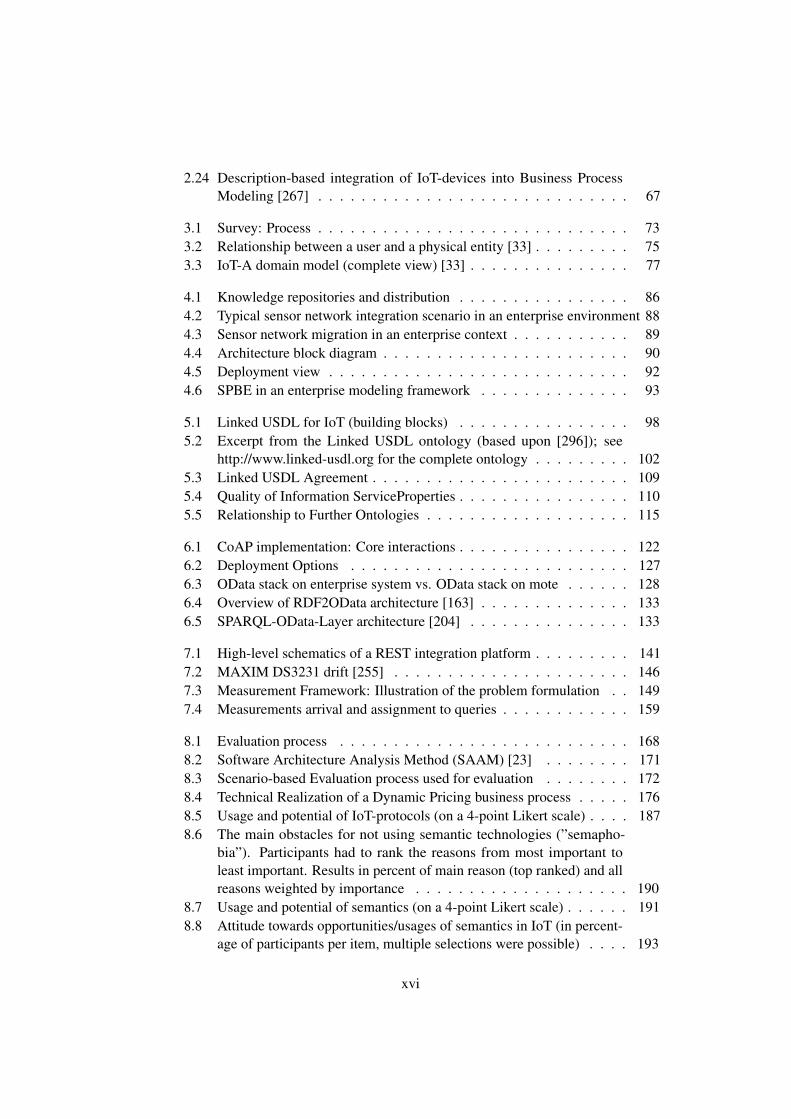
change in the upcoming years.This work does rely on the traditional Internet stack, which is often used in current
enterprise applications. Instead, we base our work on a stack on top of 6LoWPAN, UDPand the recent Constrained Application Layer Protocol (CoAP). The stack is shown inFigure 1.5. The basic ideas behind these technologies will be introduced in Chapter 2.
TCP
HTTP
Application
IP
UDP
CoAP
Application
IPv6 over LoWPAN
Internet Stack IoT Stack
Application layer
Transport layer
IP layer
Figure 1.5: Assumed IoT protocol stack
Both protocols, HTTP and CoAP, are designed according to the RESTful paradigm.RESTful architectures are currently predominant on the Internet. In 2010, there werealready five times more REST-based services available than WS*-based services. Be-tween 2007 and 2010 alone, a 900% increase of publicly available REST services wasobserved, while the number of WS-* based services merely tripled [2]. Furthermore,also in the enterprise world, more and more systems are being moved to RESTfuldesigns [279, 208]. For example, RESTful services for cloud applications and mobileapplications are currently mainly written in RESTful way [89, 328], or the initiatives ofSAP and Microsoft to make the RESTful OData protocol suite the RESTful successorof the WS-* family. Chapter 2.4 will provide a closer look at the details.
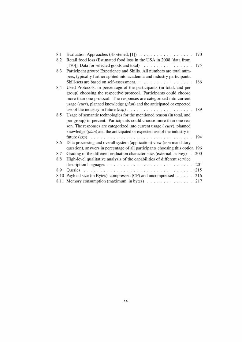
The used hardware and software platforms are visualized in Figure 1.6. The softwarewas based on the Mote Runner IoT environment [182]. Mote Runner is an (prototype)operating system and integrated development environment published by IBM ResearchZurich. Its development began in 2010. Mote Runner’s main objective is to bringmodern programming concepts to very constrained Internet of Things devices. It hasa custom-written virtual machine and compilers for C# and JAVA. It also features anextensible and accurate simulation environment. We expect the Mote Runner platformto be well suited for enterprise application developers, as most of them are familiar withone of those languages and nearly no specialized knowledge is necessary. We explainthe capabilities of the Mote Runner environment in Chapter 2.2.
The experiments were conducted on either the IRIS platform or the Waspmote Proplatform. Both platforms are Class 0 devices according to the classification in Table 1.1.They mainly differ in their capabilities to run in different hardware modes and differentpower consumption characteristics. The two platforms are introduced in Chapter 2.1.
We designed and implemented a measurement framework based on Mote Runner.
11

WasmotePRO
IRIS
Soft
war
e
Har
dw
are
Sim
ula
tio
n (
Soft
war
e) CPU
SENSORS
BAT
RADIO
SONORAN
EnergyMeasurements
TimeMeasurements
MemoryMeasurements
os
Mote manager
hal
appC# lib
java
appjava
vm sched mag
phy
Figure 1.6: Hardware/Software stack
This framework enables us to measure power consumption, all kinds of time-basedmeasurements as well as the memory consumption. Based on this, a comprehensiveview of the system state and its hardware/software profile can be determined. Wedescribe this measurement framework in Chapter 8.6.
1.5 Application-layer Energy Saving
A typical problem in wireless systems is the reduction of maintenance and on-sitework, and, thus, a decrease in the total costs of ownership. Many industrial scenariosin which IoT devices are used – like in the supply chain or in automation – oftenoperate in environments in which regular physical access to the sensor nodes and theirbatteries is not feasible. Especially, when manual (human) work is needed to replacethe power source and/or network downtime is necessary for these maintenance tasks.A lot of research on energy saving has been done on the network, MAC layer andon the hardware. Semantics-aware enterprises allow utilizing the application layer aswell. In remote monitoring scenarios, a close-to-zero on-site presence for maintenanceand administration is desirable [201, 243, 172]. The problem of such a close to zero-maintenance has several management and operational aspects attached to it: Remotemanagement of IoT devices allows configuring and reconfiguring nodes without on-siteinteractions. Frameworks such as MARWIS [393] or ADAM [364] allow the remotemanagement of devices. This includes remote code updates [62, 215]. In the operations
12
network lifetime and energy-saving are the main drivers. The longer a node is running,the less costs-intensive the system typically is. In many industrial scenarios, regularphysical access to the sensor nodes and their batteries is not a feasible option.
In terms of operations, several possible approaches address the IoT lifetime problem:Most are on the hardware-layer (CPU sleep modes, radio states) and they try to increasethe radio-off time and decrease the CPU power consumption (e.g. frequency scaling orvoltage scaling). Recently, the focus of research has shifted to some extend, towards theupper layers of a typical IoT-stack. While lower layer support for sleep states performsquite well, these functionalities are unaware of any timing or operational aspects ofthe application layer and therefore cannot leverage on that basis. A semantics-awarearchitecture makes this information available. It allows taking more decisions at theapplication layer. A concept called sleepy nodes [372, 311, 325, 172] assumes thatmany IoT-nodes will be used rather infrequently and, thus, they can sleep for longerperiods of time. Nonetheless, for the user of an IoT system a node should never appearas unavailable. Despite the energy constraints, the user of an IoT-system should beserved as best as possible taking known system behavior into account, anticipating orcalculating the expected system usage. Even in case where the system did not anticipatethe usage of a node and the node is sleeping, often there is value in information that iseither cached or arriving late.
1.6 Contributions
During the development of the work and projects, forming this thesis, a number ofcontributions have been achieved. The main contributions can be summarized asfollows:
1. IoT-Services and Classification We realized that the term ”Internet of Things-service” or ”IoT-service” is either used in a rather undefined or intuitive way andthat it is only infrequently defined. We worked on a nomenclature of the keyconcepts of the Internet of Things domain and their relationships [380, 56, 35,259], with a focus on service. Therefore, we surveyed [380, 259] the existingliterature and compared existing uses of the term IoT-service. Based on ourwork on IoT concepts we introduced – to our knowledge – one of the firstcomprehensive definition and classification of IoT-service. Compared to relateddefinitions, it does not only define service as a technical interface, but as morecomprehensive concept that takes the physical nature of the Internet of Thingsinto account.
2. Enterprise embedded IoT-services We present conceptual work on the archi-tectural building blocks and design considerations for an Internet of Thingsservice integration framework [381, 375, 382, 373, 374]. We present a novel IoT-enterprise integration framework based on a linked services approach [375, 373]to enable interoperability between a semantics-aware enterprise and IoT-devices.Its novelty is the combination of Linked Services and the distribution of services,
13

which combined, serve the needs of both enterprises and constrained IoT-devices.We argue that (distributed) Linked Services are especially well suited for IoT-applications, given their limited battery power, as well as storage and processingconstraints. Thus, Linked Services do not only enable interoperability, but alsosuit the needs of constrained devices.
3. Semantics-awareness and Linked USDL for IoT We introduce an extension toLinked USDL [76], called Linked USDL for IoT [378, 259, 382, 187], to supportthe Internet of Things. We contribute four new vocabularies to Linked USDLto support Internet of Things applications. Each of these vocabularies targets aspecific aspect of the Internet of Things. The covered aspects are events (usdl4iot-event), quality of information (usdl4iot-qoi), technical endpoints (usdl4iot-ep),and the REST paradigm (usdl4iot-rest). Furthermore, we embedded it intorelated ontologies. In the context of our semantics-aware architecture LinkedUSDL for IoT can be used to establish a bottom-up approach. In order to beable to evaluate Linked USDL and our architecture, we based our architectureevaluation on an architectural evaluation method, IoT-stakeholder workshops anda survey that allowed us to get insight into the current views of the enterpriseand academia on the IoT community with respect to semantics [34, 377, 259].The architecture evaluation showed that our architecture is capable of supportingdistributed Linked Services. We also observed a trend and some anticipationtowards RESTful designs, as well as an anticipation of an increased use ofand interest in semantics. The field also seems to be more mature nowadays,moving towards standardized technology. A need for standardization of semanticvocabularies has been identified as well as a perceived lack of training.
4. OData for very constrained IoT-devices In conjunction with our architecture,a service description and a technical protocol stack is needed. Interoperabilitybetween enterprise systems and very constrained (e.g. Class 0) IoT devices is usu-ally accomplished by having gateways that translate between the protocols usedin the IoT domain and the protocols used in the enterprise domain. We investigatea top-down and a bottom-up approach. As the protocol for the top-down approachwe chose OData [379]. OData is currently being discussed as the solution tointeroperability issues within enterprise systems. According to our knowledge,we are the first who applied OData to sensor nodes. We showed the feasibility ofthis approach for sensor nodes [379] and evaluated the solution on a stack basedon 6LowPAN and CoAP. We compared OData in its two representations JSONand ATOM with a minimal CoAP-only payload. The difference between thisCoAP baseline and the OData representation can be considered ”the price” to bepaid for a standards-conform semantic interoperability.
5. Sleepy Nodes Implementation and Monitoring Framework Sleepy Nodesare an application-related research field [372, 311, 325, 172]. Sleepy nodes aresensor nodes that might be in an energy-saving mode for some time and, thus,
14
not available for any communication. We developed a complete prototype system[372] running on two hardware platforms: MEMSIC Iris and Waspmote Pro.Compared to energy saving measurements on protocol level or on hardwarelevel (e.g. frequency or voltage scaling) we leverage on information that canbe stored in semantic repositories based up on application layer knowledgeof the application and the associated things to be monitored. We derived ahybrid energy model for both platforms. The energy model can be used tocalculate beneficial sleep times. We were able to show the general benefit ofapplication-layer sleepy nodes. We experimentally evaluated three differentstrategies: a first fit, an exhaustive approach and a heuristic named dynamicpartitioning. We demonstrated that within a time-sliced (windowed) environmentthis heuristic based upon combinable subsequent measurements further reducesthe energy consumption. It achieved only slightly worse network lifetimes thanthe exhaustive approach and generally performs better than first fit.
1.7 Outline
This thesis is divided into five parts. The remainder of this first part, Chapter 2,introduces the foundations and related work required to understand this thesis andintroduce related work. We first describe the sensor network hardware and softwareplatform used. Furthermore, we give a brief introduction to 6LoWPAN and the MAClayer protocol 802.15.4 on top of which the software platform is operating. In addition,a brief introduction into semantic modeling techniques is presented. We then presentrelated research approaches, mainly in the areas of semantic modeling area and serviceintegration.
The second part introduces our conceptual work on Internet of Things servicearchitectures. Chapter 3 presents the building blocks of an Internet of Things archi-tecture with a focus on services. We then proceed, in Chapter 4, with describing howIoT-services can be embedded into an enterprise environment.
The third part of this thesis introduces the service descriptions and protocols wedeveloped. Chapter 5 presents an extension of the Linked USDL service descriptionlanguage and further extends it towards supporting the Internet of Things. We use acustom implementation of CoAP for a reactive VM-based OS, which we present inChapter 6. In Chapter 6.3, based on the CoAP implementation, we describe how weused a downscaled OData implementation for small embedded IoT devices. Finally,Chapter 7 concludes this part by presenting a lightweight REST-style Sleepy Nodeprotocol and a window-based integration into enterprise systems.
In the fourth part, which consists of Chapter 8, we present the evaluation results ofthe aforementioned contributions. We distinguish between an empirical evaluation andan experimental evaluation.
Finally, the fifth part concludes the thesis. Chapter 9 first summarizes the thesis andthen gives further research directions that could develop out of this thesis.
15

16

Chapter 2
Foundations and Related Work
This work relates to multiple research and practice areas – ranging from networks andembedded systems, and enterprise systems and service science, to software engineering.This chapter introduces the necessary basic concepts and technologies that will assist inunderstanding the research presented in this thesis. Some attention is given to semanticmodeling technologies, the embedded software, and the hardware stack. Furthermore,we give an overview of related work. We discuss previous approaches for describingservices and semantically enrich them. We then continue with discussing enterpriseintegration based upon Web Services, REST services, and business process modeling.
2.1 Hardware
In this section, we first give a general overview of WSN/IoT sensor devices, with focuson the most well-known ones: MicaZ, TelosB, BTNode, and SUN Spot. We thenintroduce the hardware used in our experiments – IRIS and Waspmote Pro. IRIS iscomparable to TelosB-class motes. Waspmote is based on a more recent platform and itfeatures advanced capabilities like a very precise real-time clock (RTC).
2.1.1 Overview
The main components of a typical WSN/IoT sensor/actuator node are illustrated inFigure 2.1. The power supply unit (PSU) is often a battery, but it can also be the powergrid directly. Battery powered devices can have as less as 2Ah of energy, and up to85Ah and more [126]. Sometimes, IoT-devices are equipped with solar panels [10] orfurther energy harvesting technologies, such as temperature differences [342] or piezoelectronic conversion [137] .
Sensors and actuators are either on-board (often temperature) or can be ”pluggedin” on-demand. Most sensor platforms have GPIO, UART, and/or I2C interfaces toadopt to the actual needs of a specific application. Random access memory (RAM) isoften a limiting factor. As shown in Table 1.1, in Class 1 and Class 2 IoT devices itsnot more than 10 KiB or 50 KiB, down to much less than 10 KiB in Class 0 nodes.
17

Microprocessor
RAM
Power Supply Unit (PSU)
Sensors Actuators
Flash Transceiver
Figure 2.1: Main components of a typical sensor network platform
(a) MicaZ [262] (b) TelosB [263]
(c) BTNode [117] (d) SUN Spot
Figure 2.2: Sensor Nodes
18
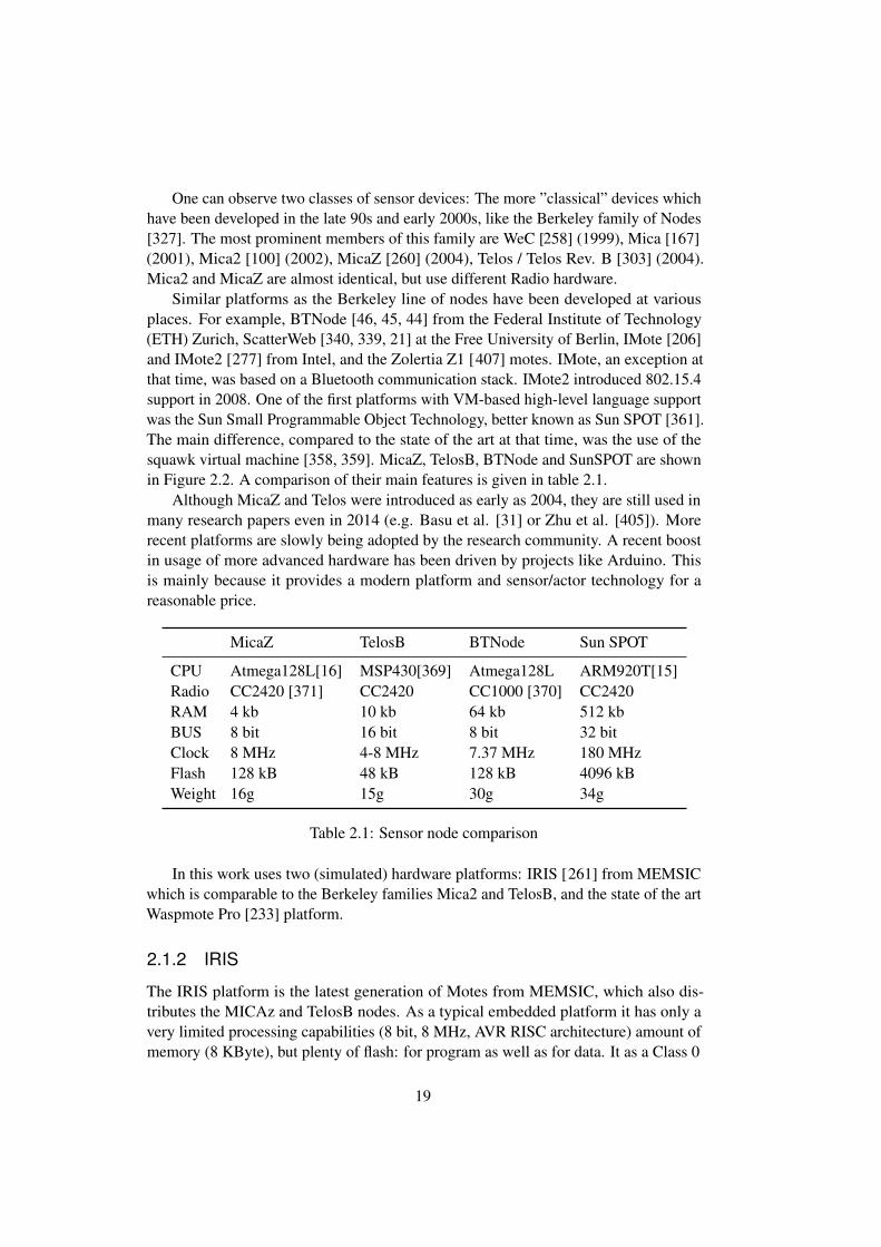
One can observe two classes of sensor devices: The more ”classical” devices whichhave been developed in the late 90s and early 2000s, like the Berkeley family of Nodes[327]. The most prominent members of this family are WeC [258] (1999), Mica [167](2001), Mica2 [100] (2002), MicaZ [260] (2004), Telos / Telos Rev. B [303] (2004).Mica2 and MicaZ are almost identical, but use different Radio hardware.
Similar platforms as the Berkeley line of nodes have been developed at variousplaces. For example, BTNode [46, 45, 44] from the Federal Institute of Technology(ETH) Zurich, ScatterWeb [340, 339, 21] at the Free University of Berlin, IMote [206]and IMote2 [277] from Intel, and the Zolertia Z1 [407] motes. IMote, an exception atthat time, was based on a Bluetooth communication stack. IMote2 introduced 802.15.4support in 2008. One of the first platforms with VM-based high-level language supportwas the Sun Small Programmable Object Technology, better known as Sun SPOT [361].The main difference, compared to the state of the art at that time, was the use of thesquawk virtual machine [358, 359]. MicaZ, TelosB, BTNode and SunSPOT are shownin Figure 2.2. A comparison of their main features is given in table 2.1.
Although MicaZ and Telos were introduced as early as 2004, they are still used inmany research papers even in 2014 (e.g. Basu et al. [31] or Zhu et al. [405]). Morerecent platforms are slowly being adopted by the research community. A recent boostin usage of more advanced hardware has been driven by projects like Arduino. Thisis mainly because it provides a modern platform and sensor/actor technology for areasonable price.
MicaZ TelosB BTNode Sun SPOT
CPU Atmega128L[16] MSP430[369] Atmega128L ARM920T[15]Radio CC2420 [371] CC2420 CC1000 [370] CC2420RAM 4 kb 10 kb 64 kb 512 kbBUS 8 bit 16 bit 8 bit 32 bitClock 8 MHz 4-8 MHz 7.37 MHz 180 MHzFlash 128 kB 48 kB 128 kB 4096 kBWeight 16g 15g 30g 34g
Table 2.1: Sensor node comparison
In this work uses two (simulated) hardware platforms: IRIS [261] from MEMSICwhich is comparable to the Berkeley families Mica2 and TelosB, and the state of the artWaspmote Pro [233] platform.
2.1.2 IRIS
The IRIS platform is the latest generation of Motes from MEMSIC, which also dis-tributes the MICAz and TelosB nodes. As a typical embedded platform it has only avery limited processing capabilities (8 bit, 8 MHz, AVR RISC architecture) amount ofmemory (8 KByte), but plenty of flash: for program as well as for data. It as a Class 0
19
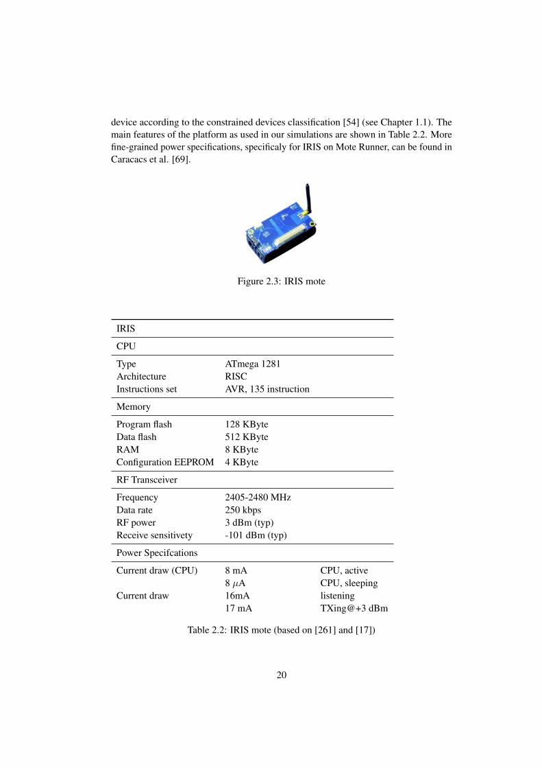
device according to the constrained devices classification [54] (see Chapter 1.1). Themain features of the platform as used in our simulations are shown in Table 2.2. Morefine-grained power specifications, specificaly for IRIS on Mote Runner, can be found inCaracacs et al. [69].
Figure 2.3: IRIS mote
IRIS
CPU
Type ATmega 1281Architecture RISCInstructions set AVR, 135 instruction
Memory
Program flash 128 KByteData flash 512 KByteRAM 8 KByteConfiguration EEPROM 4 KByte
RF Transceiver
Frequency 2405-2480 MHzData rate 250 kbpsRF power 3 dBm (typ)Receive sensitivety -101 dBm (typ)
Power Specifcations
Current draw (CPU) 8 mA CPU, active8 µA CPU, sleeping
Current draw 16mA listening17 mA TXing@+3 dBm
Table 2.2: IRIS mote (based on [261] and [17])
20

2.1.3 Waspmote Pro
The Waspmote Pro is a commercially available IoT sensor/actor node. Compared tomost previous research (e.g. those based on MicaZ or TELOSB), it did not developout of a research prototype. It uses state-of-the-art hardware and sensors, includingadvanced energy sleep modes and a precise temperature-compensated crystal clockwith RTC capabilities [234]. It is a typical embedded platform (8 bit, 14 MHz, AVRRISC architecture). The power consumption is a little bit worse on the Waspmote Procompared to the IRIS mote. Nonetheless, it features a hibernate mode where the moteconsumes very little energy, but needs some time to wakeup. In simulation, we assumedthe hibernate mode to use 0.7µA as per Waspmote datasheet [233] and confirmed byexperimental results [360]. A (simulated) hibernate reset to took 8ms. Only, when anRTC alarm is activated, is the board powered again. Possible sleeping (hibernating)interval values go from seconds to minutes, hours, and even multiple days [ 235]. Thefeatures of the platform as used in our experiments are outlined in Table 2.3
Waspmote Pro
CPU
Type ATmega 1281Architecture RISCInstructions set AVR, 135 instruction
Memory
Program flash Memory 128 KByteSerial flash up to 2GBRAM 8 KByteSD-Card 2 GBConfiguration EEPROM 4 KByte
RF Transceiver
Frequency 2405-2480 MHzData rate 250 kbpsRF power 3 dBm (typ)Receive sensitivety -101 dBm (typ)
Power Specifcations
Current draw 15 mA CPU, active55 µA sleeping0.7 µA hibernating
Current draw 12.3mA listening14 mA TXing@+3 dBm
Table 2.3: Simulated Waspmote (based on datasheets [235, 233, 234])
21

2.2 Mote Runner System
In the following we introduce the Mote Runner System. It is a VM-based operatingsystem for embedded devices that we used for software development and evaluation ofour protocols and algorithms.
2.2.1 Overview
IBM Mote Runner [73] is a run-time platform and development environment for theInternet of Things. Its operating system is suitable for a variety of CPUs (8,16, or 32bit). Its minimal requirements are are just 8 KB RAM, 64 KB Flash and an 8 bit CPU;hence, it is especially suited for IoT applications. It follows a virtualization concept.Applications (written in C# or Java) are compiled into bytecode and executed by a virtualmachine (VM). Figure 2.5 shows the main components of the Mote Runner. The MoteRunner system consists of a simulation environment, a stack or run-time environmentthat is running on the mote, and a JavaScript gateway called Sonoran to interactwith both. Sonoran1 is an off-mote, JavaScript based programming and managementenvironment [181]. Furthermore, Mote Runner has a framework for developing webapplications called Comote. It is mentioned only to ensure for completeness.
The actual environment as it is running on the mote is shown in Figure 2.6. All theapplications are written in either C# or Java. Both languages can share libraries writtenin either C# or Java. The MRv6 protocol, which is explained in detail in Chapter 2.3.3,has been written in C# but is used as part of our Java code. The operating system itself(including the VM) and the hardware abstraction layer (HAL) are written in C.
As mentioned, the Mote Runner system uses Java and C# as high-level programminglanguages. This is supposed to decrease the development time of sensor networkapplications as developers can work with a familiar programming language. Thereactive nature of the Mote Runner system is supposed to reduce concurrency-relatedprogramming errors. Nonetheless, there are some limitations compared to standard C#or Java. The main differences are as follows [181]:
• No native float and double data types. Currently only fixed comma operationsare possible
• Only 32-bit integer arithmetic. 64-bit or longer integer arithmetic is not supported
• Multi-dimensional arrays are not supported
• Run-time inspection, including getClass methods or Reflection is not supported
• Standard runtime APIs are not available.
• Enumerations are not supported1The developers of Mote Runner give the following explanation for their naming scheme [ 181]: The
Mote Runner and several of its components are themed around the Arizona desert. Mote Runner alludes toroadrunner, which is a bird in the cuckoo family. Saguaro is a large, tree-sized cactus specifies. Sonoran isthe name of a desert south of Mojave and, finally, Comote stems from and is pronounced alike coyote, theAmerican jackal or the prairie wolf.
22
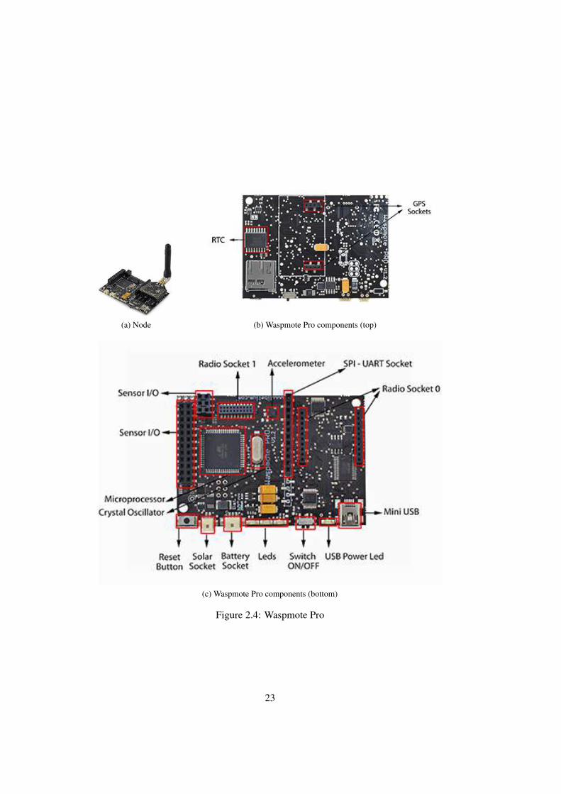
(a) Node (b) Waspmote Pro components (top)
(c) Waspmote Pro components (bottom)
Figure 2.4: Waspmote Pro
23

Sonoran gatewayjavascript engine, scriptable
shell/script
applications
browser
javascriptweb apps
Motes Simulation
apps
os
hal
apps
os
hal
apps
os
hal
eclipse
plugin
Debugger
6LoWPANtunnel
user codethird partyMote Runner
Figure 2.5: Mote Runner system overview (based on IBM [181])
• Templates are not supported
• Inner classes in C# are not supported (but are in Java)
• Multicast Delegates are not supported
• Threads/Multithreading are not supported (reactive programming model)
• Bool and Boolean arrays are not supported
• String type and String array are not supported
• Boxing is not supported
• Integer size is 16bit, not 32bit
The memory model of Mote Runner is similar to that of Java. It uses a GarbageCollector algorithm that is only executed when the VM is not active. However, asexecution of the the garbage collection algorithm takes some time, it could interferewith event deadlines.
2.2.2 Toolchain
As the Mote Runner VM is based on an optimized bytecode and not the original, thesystem comes with its own tool chain – that supports C# and Java at the same time.Libraries written in one language can be used in the other language and vice versa. Thetoolchain is shown in Figure 2.7 [73]. The parts that have been specifically writtenfor the Mote Runner system are in gray. The Java and C# compilers are the originalcompilers as delivered by Sun and the Mono project.
24

app C# lib C# app Java
Mote manager
rsrc mgrmacschedvm
serialbatterysensorsradiocpu
phy
C#
/JavaC
#/Java
C
HW
Mo
teR
un
ne
rap
ps
Figure 2.6: Mote Runner System overview – On Mote Runtime environment ([181])
C# CLI assembler3 Mote Runner assembler3
MyDelegate d;d = null;
...ldnullstloc.1
...ldc.null ; normal 16-bit nullr2dd ; delegates are 32-bitst.d.1
Figure 2. Comparison: Null-ing a delegate.
2. Converter
3. Assembler
4. Stub Generator
1. javac, csc, mcs
.java.cs
.class.dll
.sba load-file
.sxp exchange file
.sdb debug file
.sil intermediate language
library stub.java.cs
Figure 3. Mote Runner tool chain from source code toexecutables.
corresponding CLI byte codes in terms of performance on anembedded system, as we eliminate the indirection introducedby object encapsulation. Moreover, to our knowledge thereis no other embedded VM with native support for delegates.
5. Tool Chain
A virtual machine, especially one that introduces a newbyte code, cannot stand isolated. We have therefore devel-oped a complete tool chain that currently supports both Javaand C#. This tool chain allows multi-language developmentin the sense that a library written in one of the supportedlanguages can be used from any other of the supportedlanguages. For Java and C#, the process is shown in Figure 3,where tools are represented on the left side and theirresulting file artifacts on the right side — our contributionsare highlighted.
In step 1, the source code is compiled with a standardcompiler for the respective language. For Java this might bethe Sun Java SE compiler, for C# there are the Microsoftand Mono compilers. Next, in step 2, the resulting bytecode is converted by our own converter into an intermediatelanguage format, an object-oriented assembler which usesour own byte code. These assembly files are processed byour assembler in step 3 to generate compact load files thatcan be loaded to and stream-linked on the embedded device(see Section 6 for more details). When the output is a libraryinstead of an application, the assembler further generatesso-called exchange files describing the public API of thegenerated library. From these exchange files a stub generatorcreates in step 4 matching high-level language stub librariesagainst which other applications written in these high-levellanguages can link.
6. Load Files and Stream Linking
Dynamically loading and linking applications on powerconstrained devices is a crucial aspect. Stream linking allowsfor linking applications in a single pass and without costlyfix-ups (e.g. writing to flash memory) which consequentlysaves computation cycles and valuable battery resources.Moreover, communication itself, and especially radio com-munication consumes power in the same order of magnitudeas running computations on the micro-controller [13]. Tomeet our low-power design goal, it is crucial to be ableto stream link as well as transmit as little as possiblewhen loading new applications, particularly if multi-hopsare involved. Hence, we introduce a compact load-file for-mat which allows applications to be stream linked on theembedded device. In our system, a load-file is the binaryrepresentation of an assembly (cf. Section 3.)
Load files are transferred to the embedded device using aprotocol which divides the load-file into smaller units thatfill up a transmission unit including the protocol overhead.On the embedded device, a loader and linker processes theload-file chunks sequentially, internally buffering in RAMuntil enough data has been received to process some logicalstructure. The load file is designed so that modifications ofthe loaded data structures can take place in RAM beforethey are eventually flushed out to persistent storage (flash,EPPROM). This technique avoids processing stored data asecond time to perform fix-ups and reduces flash strain.
To facilitate loading and linking using a small RAMbuffer, the load file contains transient information whichonly serves to help fix up certain values. These transient dataelements are removed during loading and linking and are notwritten to persistent storage. Furthermore, to reduce the sizeof load files, padding is omitted which can be reconstructedon the fly by the loader on the embedded device.
All integer values are encoded in big endian byte order;the loader can adapt the byte order to the specific platform
Figure 2.7: Mote Runner Tool Chain (Caracas et al. [73])
Mote Runner uses a purely reactive programming model [ 73]. No further supportfor concurrency (e.g. Threads) is provided. In a reactive programming model theapplication registers methods to be executed whenever a corresponding event res, forexample a timer event. From an VM implementation point of view this requires one andonly one virtual machine stack and no synchronization [73]. Only one event handleris active at any given point in time. This typically results in simple application code.
25

Dec 2014 • Mote Runner Beta 17.1.8 Supports WiMOD880 developer kits aswell as LoRaMote devices
Jun 2014 • Mote Runner Beta 16 Supports IMST WiMOD880 developerkits as well as LoRa Blipper (v2) motes.
Dec 2013 • Mote Runner Beta 14 Improved support for Waspmote Proand IRIS.
Oct 2013 • Mote Runner Beta 13 First version for Waspmote Pro.Shipped with an improved version ofthe 6LoWPAN implementation, calledMRv6.
Mar 2013 • Mote Runner Beta 11 This version was the first to ship a6LoWPAN implementation.
Aug 2012 • Mote Runner Beta 9.0Apr 2012 • Mote Runner Beta 8.2Mar 2012 • Mote Runner Beta 8.1Mar 2012 • Mote Runner Beta 8 This was the first version we worked
with. It did not support 6LoWPAN yetand was only usable for experiments onthe MAC layer.
Aug 2011 • Meta Runner Beta 5Jun 2011 • Mote Runner Beta 4Dec 2010 • Mote Runner Beta 3.0Jul 2010 • Mote Runner SDK 2
Table 2.4: Mote Runner timeline (based on information from [182])
Nonetheless, handling of events should not require lengthy processing. Such lengthyprocessing must be split up into smaller pieces which are driven by, for example, apriority task list or by some timer event [73].
2.2.3 Version History
The Mote Runner system was still a research prototype when we conducted this research.Several Mote Runner versions were used while this thesis was written. Mote Runnercontributed to the EU-funded research project IoT-A, which also partly funded thisresearch. We used publicly available snapshots of Mote Runner, as well as versions thatwere initially only made available to project partners. In Table 2.4 we give the versionhistory of Mote Runner and a brief overview of what has been added.
26
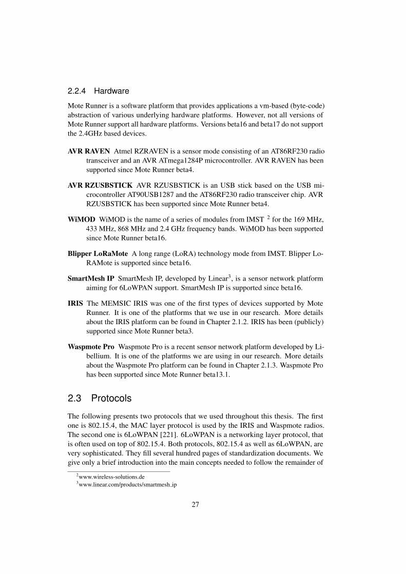
2.2.4 Hardware
Mote Runner is a software platform that provides applications a vm-based (byte-code)abstraction of various underlying hardware platforms. However, not all versions ofMote Runner support all hardware platforms. Versions beta16 and beta17 do not supportthe 2.4GHz based devices.
AVR RAVEN Atmel RZRAVEN is a sensor mode consisting of an AT86RF230 radiotransceiver and an AVR ATmega1284P microcontroller. AVR RAVEN has beensupported since Mote Runner beta4.
AVR RZUSBSTICK AVR RZUSBSTICK is an USB stick based on the USB mi-crocontroller AT90USB1287 and the AT86RF230 radio transceiver chip. AVRRZUSBSTICK has been supported since Mote Runner beta4.
WiMOD WiMOD is the name of a series of modules from IMST 2 for the 169 MHz,433 MHz, 868 MHz and 2.4 GHz frequency bands. WiMOD has been supportedsince Mote Runner beta16.
Blipper LoRaMote A long range (LoRA) technology mode from IMST. Blipper Lo-RAMote is supported since beta16.
SmartMesh IP SmartMesh IP, developed by Linear3, is a sensor network platformaiming for 6LoWPAN support. SmartMesh IP is supported since beta16.
IRIS The MEMSIC IRIS was one of the first types of devices supported by MoteRunner. It is one of the platforms that we use in our research. More detailsabout the IRIS platform can be found in Chapter 2.1.2. IRIS has been (publicly)supported since Mote Runner beta3.
Waspmote Pro Waspmote Pro is a recent sensor network platform developed by Li-bellium. It is one of the platforms we are using in our research. More detailsabout the Waspmote Pro platform can be found in Chapter 2.1.3. Waspmote Prohas been supported since Mote Runner beta13.1.
2.3 Protocols
The following presents two protocols that we used throughout this thesis. The firstone is 802.15.4, the MAC layer protocol is used by the IRIS and Waspmote radios.The second one is 6LoWPAN [221]. 6LoWPAN is a networking layer protocol, thatis often used on top of 802.15.4. Both protocols, 802.15.4 as well as 6LoWPAN, arevery sophisticated. They fill several hundred pages of standardization documents. Wegive only a brief introduction into the main concepts needed to follow the remainder of
2www.wireless-solutions.de3www.linear.com/products/smartmesh ip
27

this thesis. Furthermore, we expect at least a basic understanding of typical networkingprotocol stacks.
2.3.1 802.15.4
802.15.4 is a MAC layer protocol. It controls access to the physical medium. Thephysical medium is shared by all nodes that are in the vicinity of each other. The MACprotocol, therefore, provides a means of determining when it is safe to send and when itis not. The 802.15.4 MAC layer, which is used throughout this work, provides channelaccess management, acknowledgment of frame reception and frame validation.
The 802.15.4 protocol is defined by the 802.15.4-2003 [183] standard. The originalIEEE 802.15.4-2003 was revised in 2006 [184]. We will refer to this amendment asIEEE 802.15.4-2006. Another amendment was released in 2007 as IEEE 802.15.4a[185]. IEEE 802.15.4 defines Layer 1 (Physical Layer, PHY) and Layer 2 (MediaAccess Control Layer, MAC) of the ISO/OSI reference model. The main properties ofan IEEE 802.15.4 network are:
• Packet size of a maximum of 127 bytes
• Tree, star or mesh topology
• Good energy vs. performance tradeoff
• Up to 65,536 nodes
Frequency (MHz) Channels Data rate (kBit/s)
868 1 20 (PSS: 250)915 10 (2003), 30 (2006) 40 (PSS: 250)2400 16 250
Table 2.5: 802.15.4 Frequencies, channels and data rates
The physical layer (PHY), according the original standard, can work in threedifferent frequency bands – namely 868 MHz, 915 MHz and 2.4 GHz. 802.15.4-2006introduced a technology called Parallel Spread Spectrum (PSS) that is able to increasethe data rates in the 868 and 915 bands. Table 2.5 shows the possible 802.15.4 (not802.15.4a) frequencies, channels and data rates. The 2007 standard 802.15.4a supportsfrequencies below 1 GHz, between 3 and 5 GHz and between 6 and 10 GHz. The maindifferences between 802.15.4 and 802.15.4.a are [192] the introduction of alternative
PHYs – namely the Ultra Wide Band (UWB). Furthermore, another layer called CSS(Chirp Spread Spectrum) [192] has been introduced, which offers 14 channels in the2450 MHz band providing data rates of 1MBit/s. Channel sharing is achieved byapplying carrier sense multiple access (CSMA). Acknowledgments are provided forreliability.
28
Figure 2.8: 802.15.4 frame
The packet format of 802.15.4 consists of three parts: a header, a data chunk, anda footer. The header contains all the necessary control data (for example addresses orsequence numbers) for transmitting a frame. The layout of an IEEE 802.15.4 frame isshown in Figure 2.8. It consists of control data, a sequence number, an address, someextra security headers, the actual data to be transmitted, and a frame check sequence.The control data specifies how a receiver should interpret the frame and if it is to beacknowledged or not. The IEEE 802.15.4 MAC layer defines four different frame types:
Data frames: Date frames are used for the transport of actual data. Most protocolsbuilding on the 802.15.4 MAC layer just use data frames. The 6LoWPANimplementation used in this thesis (MRv6, see Chapter 2.3.3), for example,packages all its information (including the superframe) into MAC layer dataframes.
Acknowledgment frames: These are used to acknowledge the receipt of a frame.
Command frames: Command frames allow sending low-level commands from onenode to another.
Beacon frames: Beacon frames can be used as coordinators to structure the communi-cation with nodes.
The sequence number, following the control data, is used to match acknowledgmentsto frames. The address section contains the address of the sender of the frame and theaddress of the receiver.
2.3.2 6LoWPAN
In the following, a very brief introduction to the core ideas and concepts behind6LoWPAN is given. The complete specifications of IPv6 and 6LoWPAN consist ofseveral hundred pages; therefore, for a more thorough introduction, the specifications[221, 176] or specialized books like the one by Shelby [351] are recommended.
Notably, 6LoWPAN is considered one of the key enablers of the IoT [113], as itallows direct integration of motes into an IPv6 network [80]. 6LoWPAN is an acronymfor IPv6 over Low-power Wireless Personal Area Network. Nonetheless, some authors
29
argue (in particular, Shelby and Bormann [351]) that the term ”personal” is still onlypresent for historical reasons and they advocate 6LoWPAN as IPv6 over low-powerwireless area networks only.
The main goal of the 6LoWPAN working group was to combine traditional TCP/IPtechnology and 802.15.4. The working group had to overcome several technical hurdlesdue to the very different nature of TCP/IP on the one hand and 802.15.4 on the other.A major technical difficulty was the different payload sizes. The maximum payloadsize in 802.15.4 is 127 bytes, from which 25 bytes are already being used by theMAC header. A regular IPv6 would need 40 bytes and the UDP header needs 8bytes, thus leading to a remaining payload of not more than 54bytes (roughly 43%).In cases where encryption like AES-CCM-128 is used, the situation is even worse[143, 337]. AES-CCM-128 needs another 21 bytes, which leads to only 33 bytes (26%)being left for data [333]. This has been addressed by introducing header compressionschemes [221, 176]. Typically, the IPv6 and UDP headers can be compressed to aslittle as 7 bytes; thus, the payload can be increased to up to 95 bytes. The general ideabehind header compression is to remove all information from the header that either issuperfluous or can be determined otherwise. For example, IPv6 contains a header fieldcalled Version, which always has the value 6. This field can be omitted. Some parts ofthe address information can be deduced from the MAC header. Meanwhile, for someconfigurable settings in the IPv6 protocol standard values are assumed.
Another major issue within the working group was the maximum MTU of 1280bytes, which IPv6 requires. This lead to the need of fragmentation and defragmentationalgorithms within the 6LoWPAN layer. As fragmentation and defragmentation arerather complex tasks, and due the lack of reliability and increased energy consumption[351], the general recommendation is to avoid it whenever possible.
In the beginning, the 6LoWPAN standardization was aimed at the IEEE 802.15.4standard only and it assumed 802.15.4-specific features such as a beacon-enabled modeand association mechanisms. More recently, 6LoWPAN standardization work has beengeneralized to work with a larger range of link layers and to avoid the assumption ofIEEE 802.15.4-specific features [351].
2.3.3 MRv6
In the following, we present MRv6 as currently implemented in the Mote Runnersystem. The information given in this section is a precondition for understandingthe implementation of the sleepy node protocol in Chapter 7.5.1. MRv6 is a specific6LoWPAN (see Chapter 2.3.2) implementation for the Mote Runner system supportingUDP over 6LoWPAN and header compression according to RFC4944 and RFC6282.Its implementation is based on TDMA (Time Division, Multiple Access) mediumaccess and supports multi-hop network communication. This enables direct IPv6-basedcommunication between Internet hosts and motes in the wireless network. MRv6 isimplemented in C#, and it is treated like any other Mote Runner package. The code isfreely available and can be modified.
30

The specification of 6LoWPAN defines a design space that allows different actualimplementations. In the following, MRv6 is briefly described. For a more detailedexplanation of MRv6 and its specialties please refer to the protocol documentation[180].
2.3.3.1 Network Management
The default network stack that is shipped with the Mote Runner system is called WLIP[181]. Any mote first checks the availability of a WLIP gateway within its range. If noWLIP gateway is found, then the MRv6 library will take ownership of the radio device.From that point on it will try to join an existing network. In the current implementation,the edge mote (the root node) is responsible for network management. It managesthe tree, associations between motes, and addressing and routing. Furthermore, itimplements the protocol to communicate with the gateway (tunnel).
2.3.3.2 Communication API
The API provided by the 6LoWPAN implementation abstracts the actual communicationaway from the user application. A user application just needs to use a socket likeinterface for accessing the network. The code fragment in Listing 2.1 shows the SocketAPI for receiving a 6LoWPAN packet.
Listing 2.1: Mote Runner OnPacket socket interface
public class MirrorDemo extends UDPSocket {internal static uint LOCAL_PORT = 4711;internal static MirrorDemo socket = new MirrorDemo();
public MirrorDemo() {this.bind(LOCAL_PORT);
}
public int onPacket(Packet p) {uint len = packet.payloadLen;byte[] buf = (byte[]) Util.alloca((byte) len, Util.BYTE_ARRAY
);Util.copyData(p.payloadBuf, pa.payloadOff, buf, 0, len);buf[0]=(byte) ’x’;
try {packet.swap(len);
} catch {return 0;
}Util.copyData(buf, 0, p.payloadBuf, p.payloadOff, len);this.send(packet);return 0;
}}
31

}
2.3.3.3 Protocol details
As described, MRv6 implements a beaconing-based, multi-hop TDMA protocol. Com-munication slots between parent and children are globally assigned. The communicationconsists of a series of superframes. Figure 2.9 illustrates such a superframe. The com-munication slots between parent and children are globally assigned by the edge mote.The maximum number of nodes in the network is predefined but configurable.
…Edge M1 M2
Series of superframes
Beacon Shared Children Gap
superframe
Figure 2.9: MRv6 superframe
At the beginning of each communication period, the parent motes use superframesto send out beacons that announce the state and schedule for the communication slotsand to synchronize their clocks. Furthermore, each superframe supports a multiple-purpose shared slot. This slot can be used for association requests or responses andbroadcast messages.
Length of a slot, the time for listen operations and the gaps between slots areconstants and can be configure. The timings for a slot are specified by the (configurable)constants [180] such as:
• RECV SAFETY MILLIS: Number of milliseconds the radio is switched onbefore the slot is scheduled. This number is used to cope with clock-drift in astandard scenario, without sleeping nodes.
• SLOT RECV MILLIS: Number of milliseconds the radio is switched on in aslot.
• SLOT GAP MILLIS: Number of milliseconds after the radio is switched on andbefore the next slot.
Every mote, that is not the edge mote, is constantly switching between parent andchild mode. Figure 2.10 shows the (simplified) state diagram of the MRv6 protocol.A mote that is not part of a communication structure constantly scans for beacons
32

(CHILD SCAN BEACON) and once received (CHILD RECEIVE BEACON), it at-tempts to join the network. Whenever a mote joins the network, it attaches to a singleparent. Later on, those motes can have children of their own. If one or more possibleparents are detected, the mote evaluates them to find the closest parent that has free slots,a sufficient good link quality, and signal strength. If a suitable parent mote has beenidentified and multiple beacons from that parent mote have been received, the moteattempts to join the network. The mote sends an association request (in the shared slot)(CHILD TRANSMIT ASSOC) and waits for an answer (CHILD RECEIVE ASSOC).If no answer is received within a specified period the association attempt is repeated.The same thing happens when a mote is not receiving beacons from its parent for someintervals. In such a case, it resets its state and starts looking for a new parent again.
After the initial association to a parent, the communication between parent and itschildren work as follows: The beacon contains information about whether the parentwishes to send a packet in the shared or in the respective child slot. If either is the case,the child switches to STATE CHILD HANDLE SLOT and schedules a radio rx at anappropriate timestamp that is determined by adding a constant offset (depending on theslot type) to the last received beacon’s one. If the parent does not wish to send a packet,then the mote’s final action as a child is to check if there is a packet for its parent. Ifyes, then the mote needs to transmit it.
After the child role actions are completed, the mote switches to the parent role.The parent is initially in the state STATE PARENT SEND BEACON. It transmits itsbeacon and then any data that are to be sent through the shared slot. Next, it proceedswith iterating over all slots of its children. Whenever there is data to be sent througha slot, it transmits it, otherwise it switches to STATE PARENT HANDLE SLOT andlistens for any data from the respective child. After the last slot, the motes’ participationin the current superframe is over. It switches to the child role again and waits for thenext beacon.
PARENT SCAN
BEACON
PARENT SENT
BEACON
PARENT HANDLE
SLOT
CHILDRECEIVEBEACON
Parent
Child
CHILDSCAN
BEACON
CHILDRECEIVESHARED
CHILDHANDLE
SLOT
CHILDTRANSMIT
ASSOC
CHILDRECEIVEASSOC
Figure 2.10: MRv6 States
33
Network manages is done by so-called ”System messages”. The MRv6 protocol[180] specifies the following system messages:
Ping: A ping is specified as follows [180]: A parent sends ”ping” packets to childrenthat have been inactive for a configurable amount of time. If the child does notacknowledge the packet, it is removed from the internal list of children and,therefore, from future beacon announcements. A disassociation message is sentto the edge to notify it about the node loss. If the child is still active despite nothaving reacted to the ping, it notices its removal when inspecting the next beaconmessage, resets its state and reassociates.
Synchronization Messages: Synchronization messages are specified as follows [180]:The edge mote sends out periodic synchronization messages to all wireless nodesto synchronize their state with his own.
Information Messages: Information messages are specified as follows [180]: Nodesperiodically send information messages to the edge delivering statistics abouttransmission rates, signal strengths, communication reliability and more
Disassociation Notifications: A disassociation notification is sent by a parent motethat has lost one of its children to the edge.
Communication between motes is done in the designated time slots. A parent thatwould like to send a packet to a child has to announce a pending transmit in its beacon.This will cause the child to switch its radio receiver on in the specified time slot. Whenthe parent has no pending transmissions it will listen for messages from the child nodeinstead. Whenever a mote receives a packet from its parent it checks if it is the finalreceiver of the packet. If this be the case, the package is forwarded to the receivingsocket, as shown in Listing 2.1. If it is not the final destination of the package, itforwards the packet as required to one of its children.
Addressing works as follows [180]: The 802.15.4 header consists of the shortaddresses of the destination and source motes as allocated by the edge mote, the PANID as configured for the network, an incremental sequence number managed for thecurrent parent and child communication slot and an 802.15.4 header byte labeling thepackets as data packets expecting acknowledgments.
MRv6 supports only a subset of the 6lowpan specification: Only short or full IPv6addresses are supported and used in the compressed header. Port compression is notsupported.
2.4 Representational State Transfer
The term Representational State Transfer (REST) is closely connected with Roy Field-ing, who first described the concept [128] as a generalization of the HTTP objectmodel. It is an architecture-paradigm for distributed systems closely connected with
34
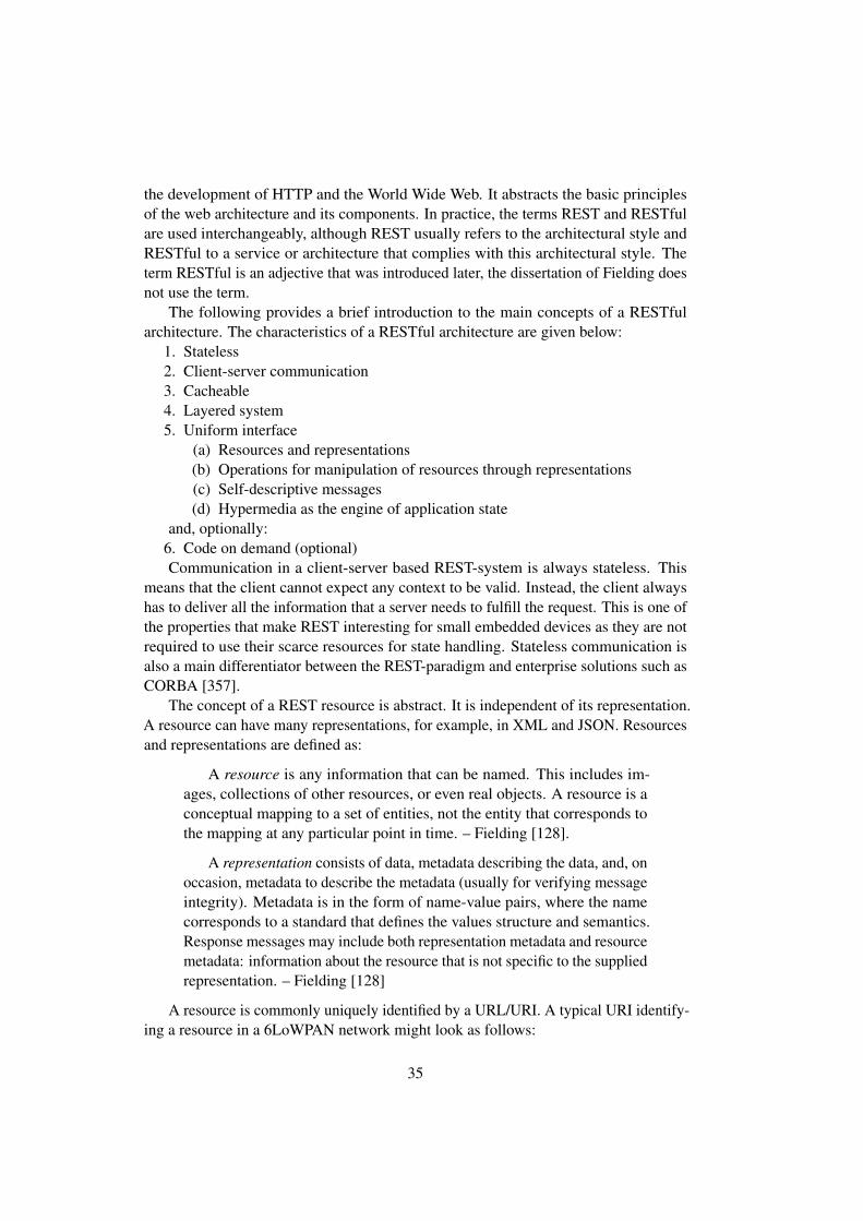
the development of HTTP and the World Wide Web. It abstracts the basic principlesof the web architecture and its components. In practice, the terms REST and RESTfulare used interchangeably, although REST usually refers to the architectural style andRESTful to a service or architecture that complies with this architectural style. Theterm RESTful is an adjective that was introduced later, the dissertation of Fielding doesnot use the term.
The following provides a brief introduction to the main concepts of a RESTfularchitecture. The characteristics of a RESTful architecture are given below:
1. Stateless2. Client-server communication3. Cacheable4. Layered system5. Uniform interface
(a) Resources and representations(b) Operations for manipulation of resources through representations(c) Self-descriptive messages(d) Hypermedia as the engine of application state
and, optionally:6. Code on demand (optional)Communication in a client-server based REST-system is always stateless. This
means that the client cannot expect any context to be valid. Instead, the client alwayshas to deliver all the information that a server needs to fulfill the request. This is one ofthe properties that make REST interesting for small embedded devices as they are notrequired to use their scarce resources for state handling. Stateless communication isalso a main differentiator between the REST-paradigm and enterprise solutions such asCORBA [357].
The concept of a REST resource is abstract. It is independent of its representation.A resource can have many representations, for example, in XML and JSON. Resourcesand representations are defined as:
A resource is any information that can be named. This includes im-ages, collections of other resources, or even real objects. A resource is aconceptual mapping to a set of entities, not the entity that corresponds tothe mapping at any particular point in time. – Fielding [128].
A representation consists of data, metadata describing the data, and, onoccasion, metadata to describe the metadata (usually for verifying messageintegrity). Metadata is in the form of name-value pairs, where the namecorresponds to a standard that defines the values structure and semantics.Response messages may include both representation metadata and resourcemetadata: information about the resource that is not specific to the suppliedrepresentation. – Fielding [128]
A resource is commonly uniquely identified by a URL/URI. A typical URI identify-ing a resource in a 6LoWPAN network might look as follows:
35

[ffff:ffff:ffff:fc03:0005]︸ ︷︷ ︸service
/temperature︸ ︷︷ ︸resource
The operations, as a part of the uniform interface, are usually implemented usingverbs, or to be more precise, HTTP-like verbs. HTTP 1.1 defines eight verbs. The fivemost important ones are:
Operation Meaning
GET Requests the representation of a resourcePUT Creates a new resource or replaces an existing onePOST Transmits data for processingDELETE Removes a resourceHEAD Is identical to GET, except that the server does not
return a body in the response, but only the meta-information contained in the HTTP headers. Theseshould be identical to the information sent in re-sponse to a GET request
Get, Put, Head and Delete operations are supposed to be idempotent. This meansoperations can be repeated with the same data on the same resources and the result(effect) shall always the same. Making multiple requests has the same effect as makingonly a single request.
Finally, the uniform interface does not only consist of resources. It also needs tofollow the hypermedia as the engine of application state (HATEOAS) principle. Itmeans that the use of hyperlinks should be the only way of navigating an applicationsstate machine. HATEOS is considered as one of the least understood constraints of theREST architecture [317].
Code on demand is the only optional feature defined by Fielding [128]. It allowsfunctionality on the client to be extended by downloading and executing code in theform of scripts. It needs to be taken into consideration that this feature was definedwhen the web was largely static and JavaScript-based applications not common.
2.5 Constrained Application Protocol
The Constrained Application Protocol (CoAP) is a cross-layer protocol defined by theIETF Constraint RESTful environments (CoRE) working group. It defines a RESTfulprotocol specifically tailored towards resource-constrained devices. CoAP is specifiedin RFC 7252 [353]. CoAP was mainly developed with UDP-based networks in mind.Nonetheless, it is possible to use CoAP with other transport layer protocols such asTCP [53], or even SMS [36]. It has also been demonstrated that CoAP has significantlylower energy consumption compared to HTTP[93], as well as lower response time andless protocol overhead than HTTP [94].
36
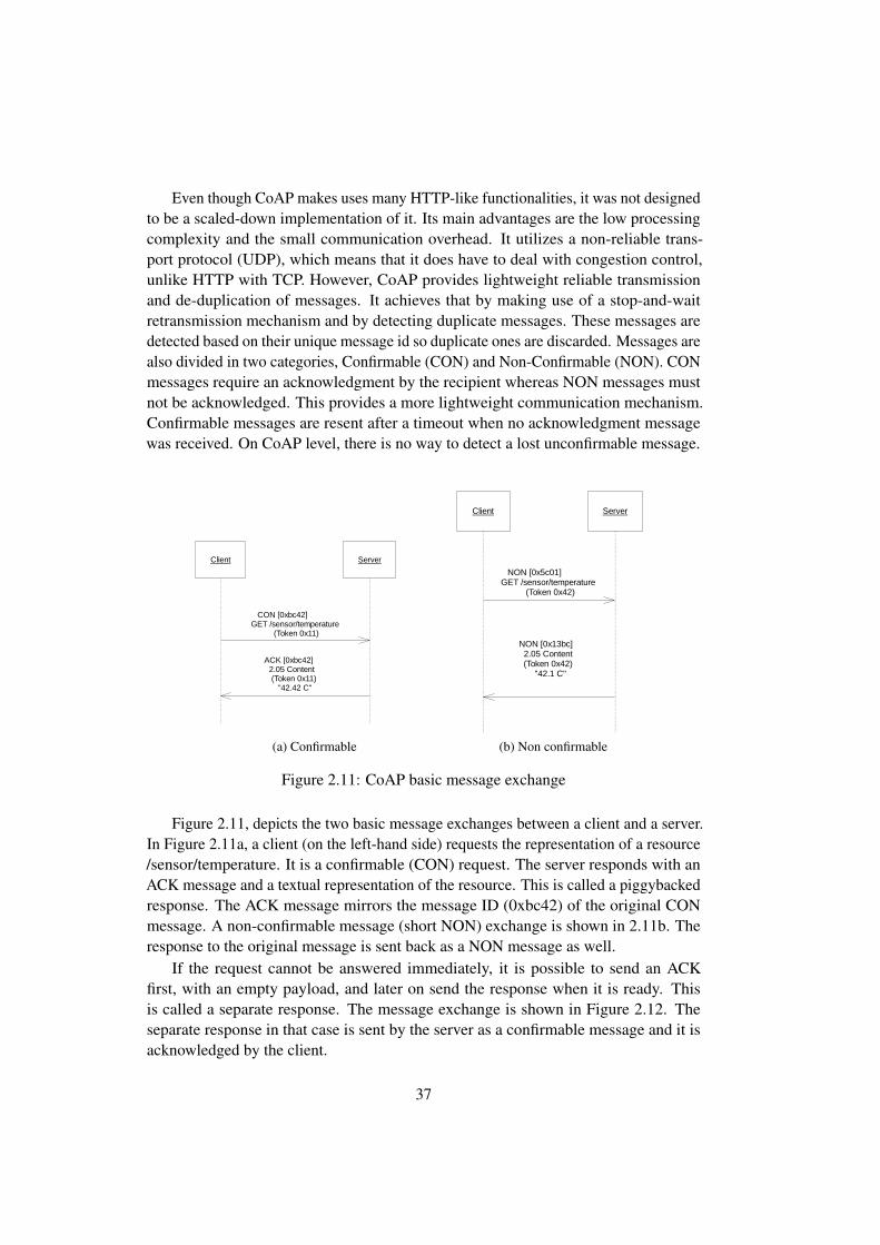
Even though CoAP makes uses many HTTP-like functionalities, it was not designedto be a scaled-down implementation of it. Its main advantages are the low processingcomplexity and the small communication overhead. It utilizes a non-reliable trans-port protocol (UDP), which means that it does have to deal with congestion control,unlike HTTP with TCP. However, CoAP provides lightweight reliable transmissionand de-duplication of messages. It achieves that by making use of a stop-and-waitretransmission mechanism and by detecting duplicate messages. These messages aredetected based on their unique message id so duplicate ones are discarded. Messages arealso divided in two categories, Confirmable (CON) and Non-Confirmable (NON). CONmessages require an acknowledgment by the recipient whereas NON messages mustnot be acknowledged. This provides a more lightweight communication mechanism.Confirmable messages are resent after a timeout when no acknowledgment messagewas received. On CoAP level, there is no way to detect a lost unconfirmable message.
1 / 1
SequenceDiagram_4_i
ACK [0xbc42]2.05 Content(Token 0x11)
"42.42 C"
CON [0xbc42]GET /sensor/temperature
(Token 0x11)
Client Server
ACK [0xbc42]2.05 Content(Token 0x11)
"42.42 C"
CON [0xbc42]GET /sensor/temperature
(Token 0x11)
(a) Confirmable
1 / 1
SequenceDiagram_6
NON [0x13bc]2.05 Content(Token 0x42)
"42.1 C"
NON [0x5c01]GET /sensor/temperature
(Token 0x42)
Client Server
NON [0x13bc]2.05 Content(Token 0x42)
"42.1 C"
NON [0x5c01]GET /sensor/temperature
(Token 0x42)
(b) Non confirmable
Figure 2.11: CoAP basic message exchange
Figure 2.11, depicts the two basic message exchanges between a client and a server.In Figure 2.11a, a client (on the left-hand side) requests the representation of a resource/sensor/temperature. It is a confirmable (CON) request. The server responds with anACK message and a textual representation of the resource. This is called a piggybackedresponse. The ACK message mirrors the message ID (0xbc42) of the original CONmessage. A non-confirmable message (short NON) exchange is shown in 2.11b. Theresponse to the original message is sent back as a NON message as well.
If the request cannot be answered immediately, it is possible to send an ACKfirst, with an empty payload, and later on send the response when it is ready. Thisis called a separate response. The message exchange is shown in Figure 2.12. Theseparate response in that case is sent by the server as a confirmable message and it isacknowledged by the client.
37

1 / 1
SequenceDiagram_5
ACK [0xaa10]
CON [0xaa10]2.05 Content(Token 0x42)
"42.12 C"
TimePasses
ACK [0x13]
CON [0x13] GET/temperature(Token 0x42)
Client Server
ACK [0xaa10]
CON [0xaa10]2.05 Content(Token 0x42)
"42.12 C"
ACK [0x13]
CON [0x13] GET/temperature(Token 0x42)
Figure 2.12: CoAP message exchange with delayed (separate) response
CoAP also implements mechanisms that allow the clients to consume services ina more complex way than just exchanging request-response pairs. Two of the mostimportant mechanisms that we also experimented with are observe and block-wisetransfer extensions.
Resources can be addressed and identified by following the CoAP URI schemeconvention. When a node receives a CoAP message, it extracts its options from theURI path and acts on the request accordingly. These options provide a means of addingrequest-specific information to the CoAP message. The IETF Core Working Groupaimed to minimize CoAP message overhead and fragmentation. The message comprisesof a 4-byte header followed by variable-length token and options sections, while the restis occupied by the optional payload. The CoAP message can fill up the UDP datagramdata section, which is roughly 80 bytes in the case of 6LoWPAN.
The format of a CoAP message is shown in Figure 2.13. The mandatory CoAPheader consists of the following components:
Ver: Protocol version. Currently only 0b01 is supported.
T: Message type. This can be either confirmable (0b00), non-confirmable (0b01),acknowledgment (0b10) or reset (0b11).
38
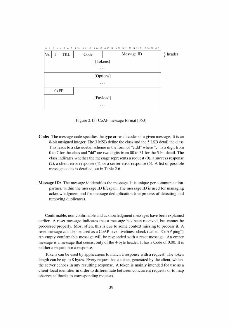
0 1 2 3 4 5 6 7 8 9 10 11 12 13 14 15 16 17 18 19 20 21 22 23 24 25 26 27 28 29 30 31
Ver T TKL Code Message ID}
header
[Tokens]
· · ·[Options]
· · ·0xFF
[Payload]
· · ·
Figure 2.13: CoAP message format [353]
Code: The message code specifies the type or result codes of a given message. It is an8-bit unsigned integer. The 3 MSB define the class and the 5 LSB detail the class.This leads to a class/detail scheme in the form of ”c.dd” where ”c” is a digit from0 to 7 for the class and ”dd” are two digits from 00 to 31 for the 5-bit detail. Theclass indicates whether the message represents a request (0), a success response(2), a client error response (4), or a server error response (5). A list of possiblemessage codes is detailed out in Table 2.6.
Message ID: The message id identifies the message. It is unique per communicationpartner, within the message ID lifespan. The message ID is used for managingacknowledgment and for message deduplication (the process of detecting andremoving duplicates).
Confirmable, non-confirmable and acknowledgment messages have been explainedearlier. A reset message indicates that a message has been received, but cannot beprocessed properly. Most often, this is due to some context missing to process it. Areset message can also be used as a CoAP-level liveliness check (called ”CoAP ping”).An empty confirmable message will be responded with a reset message. An emptymessage is a message that consist only of the 4-byte header. It has a Code of 0.00. It isneither a request nor a response.
Tokens can be used by applications to match a response with a request. The tokenlength can be up to 8 bytes. Every request has a token, generated by the client, whichthe server echoes in any resulting response. A token is mainly intended for use as aclient-local identifier in order to differentiate between concurrent requests or to mapobserve callbacks to corresponding requests.
39
Class Detail Meaning
0 00 Empty Message01 GET02 POST03 PUT04 DELETE
2 01 Created02 Deleted03 Valid04 Changed05 Content
3 xx Reserved for further use
4 00 Bad Request01 Unautorized02 Bad Option03 Forbidden04 Not Found05 Method Not Allowed06 Not Acceptable12 Precondition failed13 Request Entity Too Large15 Unsupported Content-Format
5 00 Internal Server Error01 Not Implemented02 Bad Gateway03 Service Unavailable04 Gateway Timeout05 Proxying not supported
Table 2.6: CoAP message codes as specified by [353]
Options
In earlier CoAP drafts, options were just a list of pairs (optionNo, value). This has beenchanged to a delta encoding scheme that we will briefly discuss. Each option consistsof an unsigned 16-bit option number and a value. The length of a value in bytes iscalled option length (OL). The options Op0 to Opn−1 are calculated as follows:
δ(Op0) = Op0
δ(Opi) = Opi −Opi−1 ∀i ≥ 0(2.1)
40
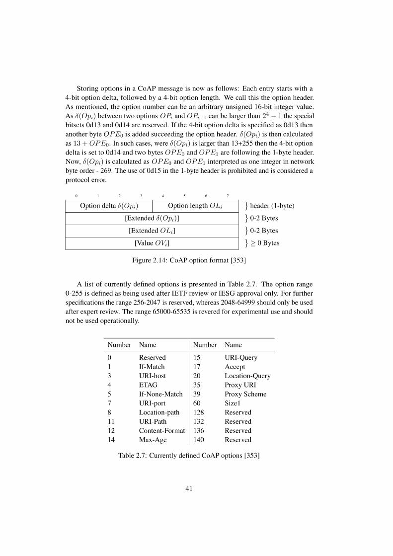
Storing options in a CoAP message is now as follows: Each entry starts with a4-bit option delta, followed by a 4-bit option length. We call this the option header.As mentioned, the option number can be an arbitrary unsigned 16-bit integer value.As δ(Opi) between two options OPi and OPi−1 can be larger than 24 − 1 the specialbitsets 0d13 and 0d14 are reserved. If the 4-bit option delta is specified as 0d13 thenanother byte OPE0 is added succeeding the option header. δ(Opi) is then calculatedas 13 +OPE0. In such cases, were δ(Opi) is larger than 13+255 then the 4-bit optiondelta is set to 0d14 and two bytes OPE0 and OPE1 are following the 1-byte header.Now, δ(Opi) is calculated as OPE0 and OPE1 interpreted as one integer in networkbyte order - 269. The use of 0d15 in the 1-byte header is prohibited and is considered aprotocol error.
0 1 2 3 4 5 6 7
Option delta δ(Opi) Option length OLi
}header (1-byte)
[Extended δ(Opi)]}
0-2 Bytes
[Extended OLi]}
0-2 Bytes
[Value OVi]}≥ 0 Bytes
Figure 2.14: CoAP option format [353]
A list of currently defined options is presented in Table 2.7. The option range0-255 is defined as being used after IETF review or IESG approval only. For furtherspecifications the range 256-2047 is reserved, whereas 2048-64999 should only be usedafter expert review. The range 65000-65535 is revered for experimental use and shouldnot be used operationally.
Number Name Number Name
0 Reserved 15 URI-Query1 If-Match 17 Accept3 URI-host 20 Location-Query4 ETAG 35 Proxy URI5 If-None-Match 39 Proxy Scheme7 URI-port 60 Size18 Location-path 128 Reserved11 URI-Path 132 Reserved12 Content-Format 136 Reserved14 Max-Age 140 Reserved
Table 2.7: Currently defined CoAP options [353]
41

Observe Option
In a client-server environment such as CoAP, a client that wants to monitor changes inthe state of a resource has no other option than to poll regularly for its state. This is ratherinefficient and it causes unnecessary load in a constrained environment. Therefore,CoAP was extended to support the observer design pattern [133]. Observers, beinginterested in changes of specific resources, register at providers called subjects [162].The subject subsequently notifies the observers whenever it changes its state. Theprotocol is based on registrations from the client and notifications from the server. Aregistration is initiated by the client. It sends a GET message to a resource with aspecial ”Observe” option. The server then adds the client to the list of observers. Now,whenever the state of the observed resource changes, the server sends a notification tothe client.
1 / 1
SequenceDiagram_1
2.05 ContentToken: 0x42Observe: 102
Payload: 42.0 Cel
2.05 ContentToken: 0x42
Observe: 101Payload: 42.1 Cel
2.05 ContentToken: 0x42
Observe: 100Payload: 42.2 Cel
GET/sesnsor/temperatureToken: 0x42 Observe:
Register
Client Server
2.05 ContentToken: 0x42Observe: 102
Payload: 42.0 Cel
2.05 ContentToken: 0x42
Observe: 101Payload: 42.1 Cel
2.05 ContentToken: 0x42
Observe: 100Payload: 42.2 Cel
GET/sesnsor/temperatureToken: 0x42 Observe:
Register
Figure 2.15: CoAP: Observe Option
The message flow of an observe in CoAP is shown in Figure 2.15. The client issuesa request to observe the resource /sensor/temperature. The token is set to 0x42. Theobserve option is set to 0, which means register. The server now adds this particularclient to the list of observers and sends notifications whenever the resource changes itsstate. The server always duplicates the token from the original requests. The observeoption, when sent from the server, is a number in ascending order. A client can usethis number to identify and distinguish one observation from the other. A client can
42

No. Name Format Length Default6 Observe uint 0-3 Byte none
Table 2.8: Observe option format [162]
deregister by issuing a new GET request with the same token as the token of theobservation and an option value of 1. It can also reject a notification. Furthermore, ifthe transmission of a notification times out regularly, the client is also removed fromthe list of observers. The option itself is shown in Figure 2.8. The notifications canbe confirmable or non-confirmable. The decision if a confirmable or non-confirmablemessage is sent is up to the server.
Block Option
The CoAP block extension [352] is used for fragmentation and defragmentation of largedata blocks at application layer. As CoAP is based on datagram transports (e.g. UDP)the size of resource representation is limited by the maximum size of a UDP packet.Even if the maximum size is not used, small amounts of data cannot be transferredwithout creating IP fragmentation or adaptation layer fragmentation. Fragmentation atthe adaptation layer or IP layer burdens the lower layers with conversation state that is,according to the CoRE working group, better managed in the application layer [352].The CoAP block-wise transfer extension now enables an application-layer blockwisetransfer of resource representations with minimal overhead and minimal communicationstate handling. The design goals of the CoAP block extensions are [352]:
1. Transfers larger than what can be accommodated in constrained- network link-layer packets can be performed in smaller blocks.
2. No hard-to-manage conversation state is created at the adaptation layer or IPlayer for fragmentation.
3. The transfer of each block is acknowledged, enabling individual retransmissionif required.
4. Both sides have a say in the block size that actually will be used.
5. The resulting exchanges are easy to understand using packet analyzer tools and,thus, quite accessible to debugging.
6. If needed, the Block options can also be used (without changes) to providerandom access to power-of-two sized blocks within a resource representation.
The CoAP block option specifies two different block options, depending on whetherit is used as part of the request (block1) or response (block2). The two options are shown
43

No. Name Format Length Default23 Block2 uint 0-3 Byte none27 Block1 uint 0-3 Byte none
Table 2.9: Block option format [352]0 1 2 3 4 5 6 7
Num M SZX
0 1 2 3 4 5 6 7 8 9 10 11 12 13 14 15
Num M SZX
0 1 2 3 4 5 6 7 8 9 10 11 12 13 14 15 16 17 18 19 20 21 22 23
Num M SZX
Figure 2.16: CoAP block option format [352]
in Table 2.9. Here, block1 is used by the client to request a resource representation inblock-wise fashion; block2 is used to send data back as blocks.
The content (option value) of the two different option values is shown in Figure2.16. A block option consists of three pieces of information [352]:
1. The block size (SZX). The block size is represented as three-bit uint. The blocksize in bytes is four plus the size of a block to the power of two. The block sizein bytes is thus calculated as Size In Bytes = 24+szx. Therefore, possible blocksizes are therefore 16,32,64...1024.
2. An indicator if more blocks are following (M). If the more flag if unset, thepayload in this message is the last. No further blocks can be requested.
3. The relative number of the block (NUM) within a sequence of blocks with thegiven size. It specifies the block number being requested (block1) or provided(block). The first block is number 0.
The basic interaction paradigms are shown in Figure 2.17a and Figure 2.17b. Thefirst case is called early negation. The second case is called late negotiation. In earlynegotiation, the client already knows or anticipates the need for a blockwise transfer. Itsends a block size proposal (block 1). The server agrees with this block size and, fromnow on, all return messages carry 64 bytes of payload. The last return message maycarry between 1 byte and 64 bytes.
In case of late negotiation the client does not anticipate any block-wise transferand, therefore, does not send a blockwise request to the server. The server, however,requests a blockwise transfer and sends a proposal of a blocksize of 128 bytes. But theclient cannot handle such big blocks and requests a blocksize of 64 bytes instead.
44

1 / 1
SequenceDiagram_3
ACK [MID=45], 2.05 Content, 2:5/0/64
CON [MID=45], GET, /description, 2:5/0/64
ACK [MID=44], 2.05 Content, 2:4/1/64
CON [MID=44], GET, /description, 2:4/0/64
ACK [MID=43], 2.05 Content, 2:1/1/64
CON [MID=43], GET, /description, 2:1/0/64
ACK [MID=42], 2.05 Content, 2:0/1/64
CON [MID=42], GET, /description, 2:0/0/64
Client Server
ACK [MID=45], 2.05 Content, 2:5/0/64
CON [MID=45], GET, /description, 2:5/0/64
ACK [MID=44], 2.05 Content, 2:4/1/64
CON [MID=44], GET, /description, 2:4/0/64
ACK [MID=43], 2.05 Content, 2:1/1/64
CON [MID=43], GET, /description, 2:1/0/64
ACK [MID=42], 2.05 Content, 2:0/1/64
CON [MID=42], GET, /description, 2:0/0/64
(a) Early message negotiation
1 / 1
SequenceDiagram_4
ACK [MID=46], 2.05 Content, 2:5/0/64
CON [MID=46], GET, /description, 2:5/0/64
ACK [MID=45], 2.05 Content, 2:4/1/64
CON [MID=45], GET, /description, 2:4/0/64
ACK [MID=44], 2.05 Content, 2:3/1/64
CON [MID=44], GET, /description, 2:3/0/64
ACK [MID=43], 2.05 Content, 2:2/1/64
CON [MID=43], GET, /description, 2:2/0/64
ACK [MID=42], 2.05 Content, 2:0/1/128
CON [MID=42], GET, /description
Client Server
ACK [MID=46], 2.05 Content, 2:5/0/64
CON [MID=46], GET, /description, 2:5/0/64
ACK [MID=45], 2.05 Content, 2:4/1/64
CON [MID=45], GET, /description, 2:4/0/64
ACK [MID=44], 2.05 Content, 2:3/1/64
CON [MID=44], GET, /description, 2:3/0/64
ACK [MID=43], 2.05 Content, 2:2/1/64
CON [MID=43], GET, /description, 2:2/0/64
ACK [MID=42], 2.05 Content, 2:0/1/128
CON [MID=42], GET, /description
(b) Late message negotiation
Figure 2.17: CoAP basic message exchange
2.6 OData
In the following, we will briefly present the Open Data Protocol (OData) [274] protocol.OData is a recent data access protocol based on widely-used technologies (HTTP,AtomPub and JSON). OData, compared to the formerly predominant SOAP services,follows a REST-based approach, aims for semantic interoperability, and follows a morelightweight approach than traditional XML-based web services.
2.6.1 Overview
OData is a pure data access protocol on top of already existing application-layerprotocols. It is based on widely-used technologies – namely HTTP, AtomPub andJSON. OData consists of the following four main parts:
• OData Protocol: OData specifies a protocol defining how clients can query andmanipulate data sources. It supports CRUD operations and different serialization
45
formats, such as Atom Syndication Format and JSON. OData defines a querylanguage as an extension of the URI. This query language provides a set of queryoptions that allows clients to specify the data in which they are interested.
• OData data model: The structure of the data is defined by an abstract datamodel called Entity Data Model (EDM). It can be seen as a realization of thewell-known entity relationship model, where data is modeled as entities andassociations among those entities. An OData service provides a Service MetadataDocument that defines the EDM-based model of the service in the XML-basedConceptual Schema Definition Language (CSDL).
• OData service: An OData service exposes a callable endpoint that allows ac-cessing data or calling functions. It implements the OData protocol and uses theOData data model.
• OData client: An OData client accesses an OData service through the ODataprotocol and the known OData data model.
Chapter 2.6.3 will first describe the main concepts of OData services, as well astheir relationships with resources and the OData data model. Thereafter, we will discusspossible data representations (Chapter 2.6.4).
2.6.2 Version History
OData is a relatively young development. The development started in 2007. A firstOData version was released to the public in 2010. OData has been constantly andsignificantly enhanced since. The first release of OData was followed by OData version2.0 [269] in 2011. The first version that gained widespread popularity was ODataversion 3.0 [274], which was released in 2012. OData subsequently was standardizedby OASIS with the latest release – OData version 4.0 [287]– in 2014. OASIS submittedOData to ISO in order to establish an international standard. OData version 3.0 was thefirst that introduced comprehensive modeling capabilities that were further extended inOData version 4.0. More information on the differences between OData version 3 andOData version 2, respectively between OData version 4.0 and OData version 3.0, can befound in the official OData specifications [269, 274, 287] and technical documentation[368].
2.6.3 Services, Resources and Data Model
OData uses URIs to reference resources and to specify queries. An URI as used inOData can consist of three different parts: A service root URI, the resource path anda query. The service root URI identifies the root of an OData service. The resourcepath identifies the resource the service consumer wants to interact with (for examplea specific temperature sensor, or some actor). Such a resource commonly addresses
46
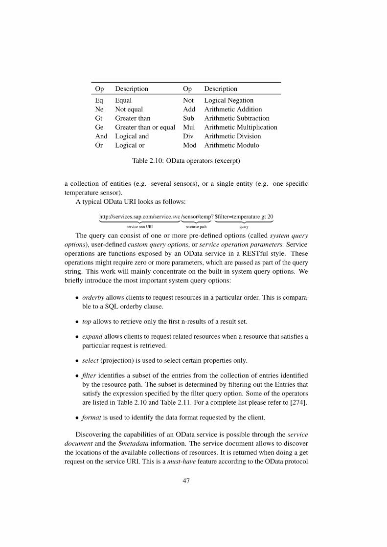
Op Description Op Description
Eq Equal Not Logical NegationNe Not equal Add Arithmetic AdditionGt Greater than Sub Arithmetic SubtractionGe Greater than or equal Mul Arithmetic MultiplicationAnd Logical and Div Arithmetic DivisionOr Logical or Mod Arithmetic Modulo
Table 2.10: OData operators (excerpt)
a collection of entities (e.g. several sensors), or a single entity (e.g. one specifictemperature sensor).
A typical OData URI looks as follows:
http://services.sap.com/service.svc︸ ︷︷ ︸service root URI
/sensor/temp︸ ︷︷ ︸resource path
? $filter=temperature gt 20︸ ︷︷ ︸query
The query can consist of one or more pre-defined options (called system queryoptions), user-defined custom query options, or service operation parameters. Serviceoperations are functions exposed by an OData service in a RESTful style. Theseoperations might require zero or more parameters, which are passed as part of the querystring. This work will mainly concentrate on the built-in system query options. Webriefly introduce the most important system query options:
• orderby allows clients to request resources in a particular order. This is compara-ble to a SQL orderby clause.
• top allows to retrieve only the first n-results of a result set.
• expand allows clients to request related resources when a resource that satisfies aparticular request is retrieved.
• select (projection) is used to select certain properties only.
• filter identifies a subset of the entries from the collection of entries identifiedby the resource path. The subset is determined by filtering out the Entries thatsatisfy the expression specified by the filter query option. Some of the operatorsare listed in Table 2.10 and Table 2.11. For a complete list please refer to [274].
• format is used to identify the data format requested by the client.
Discovering the capabilities of an OData service is possible through the servicedocument and the $metadata information. The service document allows to discoverthe locations of the available collections of resources. It is returned when doing a getrequest on the service URI. This is a must-have feature according to the OData protocol
47

Function Description
bool startswith(string p0, string p1) Checks if string p0, starts withthe string p1
int length(string p0) Length of stringstring trim(string p0) Removes whitespaces at begin-
ning and endstring toupper(string p0) Transforms to upper casestring tolower(string p0) Transforms to lower casedouble round(double p0) Arithmetic roundingdouble floor(double p0) next lowest integer value by
rounding down
Table 2.11: OData functions (excerpt)
specification. In addition, every service should present information about the structureand organization of all the resources. This is done by appending a $metadata pathsegment to the path. The result is in Common Schema Definition Language (CSDL)[271] format.
2.6.4 Data Representation
The OData protocol was not designed to work with constrained devices. It was originallyintended to work with more heavy-weight clients, like in communicating enterprise sys-tems or communication between an enterprise system and a mobile phone. The ODatastandard defines two ways for data representation (sometimes called serialization), ofwhich one is rather heavyweight: ATOM/AtomPub [282] and JSON [98]. The twoformats are used to represent the result of a service call. They are also used to modelthe service itself using the common schema definition language as described earlier.
ATOM is an XML based format that defines XML elements and their meaning. It isdefined in RFC 4287 [282] and its roots are in the structured description of entry baseddata feeds. Each feed can contain an arbitrary number of entries. Each entry holdssome content. AtomPub (Atom Publishing Protocol) defines the notion of a service.A service consists of one or more collections. AtomPub also defines a set of RESTfulinteractions for accessing a service.
The relation between ATOM/AtomPub and EDM is shown in Figure 2.18. EachAtomPub service corresponds to an entity container in EDM. Collections and theirfeeds can be directly mapped onto entity sets. An Atom entry corresponds directly toan EDM entity. In the following we will refer to ATOM/ATOMPub simply as ATOM,as it always goes together.
JSON is a standard format originally designed for the serialization of JavaScriptobjects. It defines a text format for serializing (structured) data. All data is serializedas an unordered collection of name/value pairs. JSON, other than JSON-LD, does not
48

Service
Collection/Feed
Entry
Property
Entity Container
Entity Set
Entity
Property
S
C/F C/F
S S S S
P P P P P P P PP P
ATOM EDM
Figure 2.18: OData: Relationship between ATOM and the entity data model [82]
define any further semantics. OData extends the JSON format by defining conventionsfor the name-value pairs that annotate a JSON object, property, or array. For thispurpose, OData defines a set of a set of canonical annotations for control information,such as IDs, types, and links, and custom annotations that may be used to add domain-specific information.
The OData protocol, its two representations, and the CDSL/EDM come with theirown comprehensive specifications that go beyond what can be described here. Moredetailed information can be found in the OData specifications. OData v3 consists ofseven standardization documents, each of hundreds of pages. Most important are theOData Version 3.0 Core Protocol [274], OData Version 3.0 Common Schema DefinitionLanguage (CSDL) [271], the Url Conventions [273] and the two data representation:Atom Format [270] and JSON Verbose Format [272].
2.7 Modelling of Vocabularies and Ontologies
This section will give a brief overview on how to model Linked Services with SemanticWeb technologies to an extent that makes this work self-contained and comprehensiblewithout deep prior understanding of semantic web technologies like RDF, OWL orSPARQL. An introduction to these technologies is provided by Segaran et al. [343],Allemang and Hendler [11] or Hitzler et al. [168]. The W3C standards4 are also a goodsource of information.
2.7.1 Resource Description Framework
The Resource Description Framework (RDF) is a set of W3C specifications used forthe conceptual description or modeling of information of any kind with the aim ofdata interchange. The main idea behind RDF is to express statements about resources.These statements are expressed as (subject, predicate, object) triples and constitute a
4http://www.w3c.org/RDF
49

directed graph. It is important to distinguish between RDF and its schema languageRDF(s). RDF itself has only a very limited vocabulary 5. RDF(s) is used to model RDFvocabularies, describing the elements of a domain. The relationship between RDF andRDF(s) is the same as between XML and XML-Schema. In the following tables, theorigin of a concept is determined by its prefix, which is either rdf: or rdfs:. The mainconcepts of RDF/RDFS are described in Table 2.12.
Concept Identifier Description
Resource rdfs:Resource All things described by RDF are called resources, and are in-stances of the class rdfs:Resource. This is the class of everything.All other classes are subclasses of this class. rdfs:Resource is aninstance of rdfs:Class.
Class rdfs:Class This is the class of resources that are RDF classes. rdfs:Class isan instance of rdfs:Class.
Literal rdfs:Literal The class rdfs:Literal is the class of literal values such as stringsand integers. Property values such as textual strings are examplesof RDF literals. Literals may be plain or typed. A typed literalis an instance of a datatype class. This specification does notdefine the class of plain literals. rdfs:Literal is an instance ofrdfs:Class. rdfs:Literal is a subclass of rdfs:Resource.
Datatype rdfs:Datatype rdfs:Datatype is the class of datatypes. rdfs:Datatype is bothan instance of and a subclass of rdfs:Class. Each instance ofrdfs:Datatype is a subclass of rdfs:Literal.
Property rdf:Property rdf:Property is the class of RDF properties. rdf:Property is aninstance of rdfs:Class.
Table 2.12: Main concepts of RDF/RDFS (Source: Brickley et al. [61])
The property concept of RDF is describing a relationship between two resources(subject and object resource). Properties can be further defined, for example, they canhave a destination (range) and a source (domain). The main means of extending andfurther defining a RDFS:property is described in Table 2.13.
Concept Identifier Description
Range rdfs:range dfs:range is an instance of rdf:Property that is usedto state that the values of a property are instances ofone or more classes.
Domain rdfs:domain rdfs:domain is an instance of rdf:Property that isused to state that any resource that has a given prop-erty is an instance of one or more classes.
5also often called ontology. The terms ontology and vocabulary are often used interchangeable inRDF-related literature.
50

Type rdf:type rdf:type is an instance of rdf:Property that is used tostate that a resource is an instance of a class.
Sub class rdfs:subClassOf The property rdfs:subClassOf is an instance ofrdf:Property that is used to state that all the instancesof one class are instances of another
Sub property rdfs:subPropertyOf The property rdfs:subPropertyOf is an instance ofrdf:Property that is used to state that all resourcesrelated by one property are also related by another.
Label rdfs:label rdfs:label is an instance of rdf:Property that maybe used to provide a human-readable version of aresource’s name.
Comment rdfs:Comment rdfs:comment is an instance of rdf:Property that maybe used to provide a human-readable description ofa resource.
Table 2.13: Concepts further defining properties. (Source: Brickley et al. [61])
RDF predefines some properties, as shown in Table 2.14. Each property is applicableto a given domain (subject) and a range (object).
Name Description Domain Range
rdf:type The subject is an instance of a class rdfs:Resource rdfs:Classrdfs:subClassOf The subject is a subclass of a class. rdfs:Class rdfs:Classrdfs:subPropertyOf The subject is a subproperty of a property. rdf:Property rdf:Propertyrdfs:domain A domain of the subject property. rdf:Property rdfs:Classrdfs:range A range of the subject property. rdf:Property rdfs:Classrdfs:label A human-readable name for the subject. rdfs:Resource rdfs:Literalrdfs:comment A description of the subject resource. rdfs:Resource rdfs:Literalrdfs:seeAlso Further information about the subject re-
source.rdfs:Resource rdfs:Resource
rdfs:isDefinedBy The definition of the subject resource. rdfs:Resource rdfs:Resourcerdf:value Idiomatic property used for structured values rdfs:Resource rdfs:Resourcerdf:subject The subject of the subject RDF statement. rdf:Statement rdfs:Resourcerdf:predicate The predicate of the subject RDF statement. rdf:Statement rdfs:Resourcerdf:object The object of the subject RDF statement. rdf:Statement rdfs:Resource
Table 2.14: RDF properties (Source: Brickley et al. [61], Section 6.2 – shortendexcerpt)
2.7.2 Turtle Notation
The Terse RDF Triple Language (short: Turtle) is a format developed by Dave Beckettand Tim Bernes-Lee [38] to express data in RDF. It is one of the many possible concretesyntaxes for RDF. Others include RDF/XML [37], JSON [102], and Notation 3 (N3)[43]. Turtle is a compatible subset of N3 and currently the most used notation language,recognized for its compactness and human readability. We will shortly introduce the
51

main concepts of Turtle by example. For a more thorough introduction to Turtle, pleaserefer to Hitzler et al. [168] or the Turtle specification [38].
The following fragment shows the description of a class service. It has a label andis a subclass of some other class (gr:ProductOrService).
Listing 2.2: Modelling of classes with RDF
example:Service a rdfs:Class;rdfs:label "Service"@en ;rdfs:subClassOf gr:ProductOrService .
Properties are defined in the same manner: We introduce a property examples:includeswhich is a rdf:Propoerty. As mentioned before properties can be hierarchical as well.Example:includes is a subproperty of gr:includes, and it has a domain and a range. So,the includes property can be applied to any example:ServiceOffering and connect itto a example:Service. In other words, every example:ServiceOffering can include anexample:Service.
Listing 2.3: Modelling of properties with RDF
example:includes a rdf:Property;rdfs:label "includes"@en ;rdfs:subPropertyOf gr:includes;rdfs:domain example:ServiceOffering;rdfs:range example:Service .
Concrete instances can be created with the same syntax. The following codefragment models a service MyService, a service offering MyServiceOffering and letsMyServiceOffering include MyService.
Listing 2.4: Concrete instance of a class modeled with RDF
:MyService a example:Service;rdfs:label "MyService is a concrete instance of a class"@en .
:MyServiceOffering a example:ServiceOffering;example:includes :MyService .
Within this thesis, we use Turtle notation for writing RDF.
2.7.3 Web Ontology Language
OWL, the Web Ontology Language, is a knowledge representation language for mod-eling ontologies and knowledge bases. Like RDF, its main concern is to define theterminology for a given domain. Currently, two versions are available. Work on thefirst OWL specification [257] started in 2002 and it was first published in 2004. Thelater OWL 2 specification [392] was published as a W3C recommendation in late 2009.OWL is based on description logic [20], which is a decidable subset of first-order
52

predicate logic. The OWL standard defines three different flavors or variants of OWLwith increasing expressivity: OWL Lite, OWL DL and OWL full, with OWL Lite ⊂OWL DL ⊂ OWL full ⊂ First Order Logic.
OWL Lite is decidable and has complexity of ExpTime: The class of decisionproblems solvable by a deterministic turing machine in O(2p(n)) time. OWL DL is alsodecidable and has a complexity of NExpTime. NExpTime are decision problems thatcan be solved by a non-deterministic Turing machine using O(2p(n)) time. OWL Fullincludes all features of RDFS. It is undecidable.
Instances
Instances, often called individuals, are modeling elements in OWL. They can beseen as objects or instances of classes. They often represent real-world objects. Aninstance/individual can be part of a class (Chapter 2.7.3). The class membership ofan OWL individual can either be direct (implicitly) defined or deduced through itsproperties (Chapter 2.7.4). In OWL, there are no unique identifiers for instances. Twodifferent identifiers can refer to the same objects.
Classes
A class is a set of instances. It is used to express that members of a class share certainproperties. Every instance is a member of owl:Thing. It is the most general classpossible. The empty class, which does not contain any instances, is called owl:Nothing.
Concept Identifier Description
Intersection owl:intersectionOf intersection of two classesUnion owl:unionOf constructs the union of two given classesComplement owl:complementOf complement of two classesEnumerated class owl:oneOf one of the listed classes
Table 2.15: OWL class constructors. Source: [257]
Classes can also be constructed through class constructors. Some class constructorsare listed in the Table 2.15. The union constructor, for example, takes two classes Aand B, and constructs the class consisting of all instances of class A and all instances ofclass B. The following code fragment shows the use of a union. The meaning of thecode fragment is explained in Chapter 5. Important at this point is the domain of theproperty hasInteractionPoint. It is defined as an owl:Class, and more specifically, asthe union of services (usdl:Service) and service models (usdl:ServiceModel):
Listing 2.5: OWL class example
usdl:hasInteractionPoint a rdf:Property;
53

rdfs:domain [a owl:Class; owl:unionOf (usdl:Service usdl:ServiceModel)];
rdfs:range usdl:InteractionPoint .
2.7.4 Properties
Properties are used to express relationships between two objects (instances, classes,or datatypes). Properties, similar to classes, can be hierarchical. In OWL only binaryrelationships are possible, between a domain and a range, similar to the concept in RDF.OWL distinguishes two types of properties: (i) Datatype properties and (ii) Objectproperties. A datatype property relates instances to RDF literals or datatypes. OWLuses the owl:DatatypeProperty type for modeling this relationship. Object properties,formulated using owl:ObjectProperty, relate two instances of two classes.
Concept Identifier
Min. cardinality owl:minQualifiedCardinalityMax. cardinality owl:maxQualifiedCardinalityLocal reflexitivity owl:hasSelfKey owl:hasKeySymmetric owl:SymetricPropertyAsymmetric owl:AsymmetricPropertyReflexive owl:ReflexivePropertyIrreflexive owl:IrreflexivePropertyTransitivity owl:TransitivePropertySource: [257]
2.7.5 SPARQL
SPARQL (SPARQL Protocol and RDF Query Language) is a query language for RDF.It is able to retrieve and manipulate data stored in RDF format, for example, in a triplestore. Since RDF can be interpreted as directed graphs, SPARQL works with graphpatterns. The results of SPARQL queries can be either results sets or RDF graphs.SPARQL can be seen as the SQL for the semantic web.
2.8 Data Reduction
In our experiments, we included a compressed version of both XML and JSON. Previousresearch at the CDS working group [110] and similar research, e.g. by Marcelloniet al. [246] and Sadler[331], has shown that standard compression algorithms have aquite decent compression performance, also compared to specialized algorithms. Inthe following, we briefly summarize these results and then compare to the possiblealternatives.
54
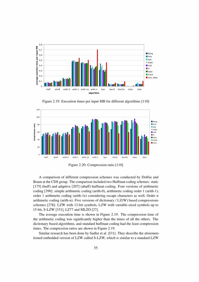
10 IAM-10-003
0
0,1
0,2
0,3
0,4
0,5
0,6
0,7
0,8
huff ahuff arith-0 arith-1 arith-1e arith-n lzss lzw12 lzw15v mlzo slzw
algorithm
avera
ge e
xect
ion
tim
e p
er
inp
ut
MB
fping
hna
qos
stats
mid
rt
topo
trace
wsn_data
Figure 2: Average time for compressing CTI-Mesh and Tarwis-Measurements with the different algorithms on a MAC OS X platform.
network parts. The different LZW variants (lzss, lzw12, lzw15v and mlzo)target roughly similar values between 82% and 88% for WMN and 49%and 60% for WSN data. As expected, the huffman implementations andthe simple arithmetic coding yield almost the same results, around 54%compression ratio regardless of the type of input data. The only surprisingresult is the bad performance of SLZW, especially in regard to the sensornetwork data set. Although it has been specifically designed for WSNs, thealgorithm provides with 35% the poorest compression ratio in this evalu-ation. This may partially be accounted to a lack of a fixed-size format oflogfile entries due to dynamically-sized neighborhood lists, which prohibitsthe exploitation of input transformation, and thus the advantage of using asmall cache.
3.3.2 Execution time
Another important metric to evaluate a compression algorithm is its ex-ecution time. Naturally, the more time is spent for computation, the moreenergy will be consumed by the processor. Furthermore, in case compres-sion is applied in the domain of sensor networks or generally on embeddeddevices, operating systems may not support concurrent operations. Thus,a long-running execution of a compression algorithm will block the proces-sor for a significant amount of time, in which, e.g., reactivity to importantoperational events is not given, the node is not responsive, and in the worst
Figure 2.19: Execution timer per input MB for different algorithms [110]
Evaluation 9
0
20
40
60
80
100
120
huff ahuff arith-0 arith-1 arith-1e arith-n lzss lzw12 lzw15v mlzo slzw
algorithm
com
pre
ssio
n r
ati
o
fping
hna
qos
stats
mid
rt
topo
trace
wsn_data
Figure 1: Average compression ratio of the different algorithms obtainedfor CTI-Mesh and Tarwis-Measurements.
network with no constraints on resource usage, the following results reflectsolely characteristics of the compression step.Due to need for a tool for memory estimations, the experiments have beenexecuted on a 2.4 GHz Intel x86 machine running MAC OS X. Except forthe execution time, results will not differ when profiling is run on wirelessmesh or sensor nodes. The execution time measurements provided belowwill nevertheless offer a clear intuition towards the performance on respec-tive hardware, yet have to be repeated for a dedicated system on demand.
3.3.1 Compression ratio
The first and foremost parameter that seeks attention is the compressionratio a certain algorithm can provide. The compression ratio is calculatedas follows:
compression ratio = 100−(compressed size∗100)/uncompressed size
Due to the presence of redundancy in all data traces, the compressionratio is in general higher than 50%, see Figure 1. The best compressionratio with an average of 92% for the wireless mesh data and 67% for thesensor network traces can be granted by the order-n arithmetic coding.For the former set, the algorithm clearly benefits from the great codingpossibilities since the WMN traces feature many IP addresses with similar
Figure 2.20: Compression ratio [110]
A comparison of different compression schemes was conducted by Dolfus andBraun at the CDS group. The comparison included two Huffman coding schemes: static[175] (huff) and adaptive [207] (ahuff) huffman coding. Four versions of arithmeticcoding [398]: simple arithmetic coding (arith-0), arithmetic coding order 1 (arith-1),order 1 arithmetic coding (arith-1e) considering escape characters as well, Order narithmetic coding (arith-n). Five versions of dictionary / LZ(W) based compressionsschemes [278]: LZW with 12-bit symbols, LZW with variable-sized symbols up to15-bit, S-LZW [331], LZ77 and MLZO [27].
The average execution time is shown in Figure 2.19. The compression time ofthe arithmetic coding was significantly higher than the times of all the others. Thedictionary based algorithms, and standard huffman coding had the least compressiontimes. The compression ratios are shown in Figure 2.19.
Similar research has been done by Sadler et al. [331]. They describe the aforemen-tioned embedded version of LZW called S-LZW, which is similar to a standard LZW
55
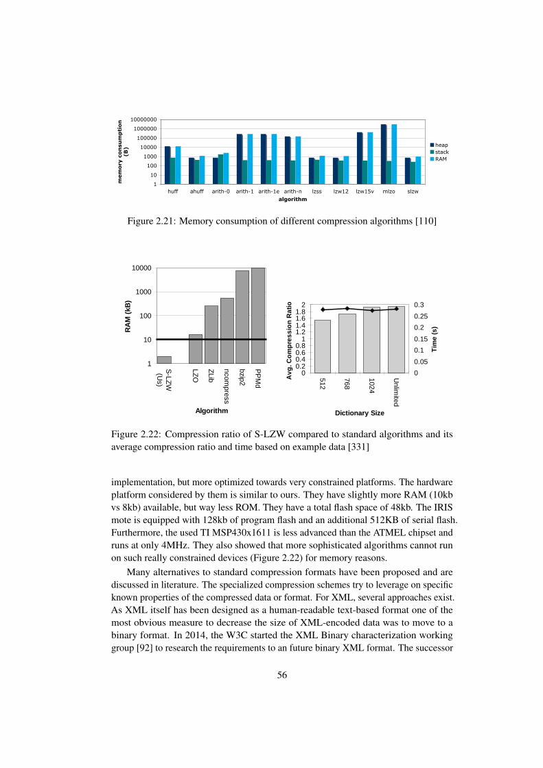
12 IAM-10-003
1
10
100
1000
10000
100000
1000000
10000000
huff ahuff arith-0 arith-1 arith-1e arith-n lzss lzw12 lzw15v mlzo slzwalgorithm
mem
ory
co
nsu
mp
tio
n
(B) heap
stackRAM
Figure 4: Peak RAM memory usage of the different algorithms without I/Oin bytes.
Figure 3 displays the text segment occupation in bytes (B) by the variousimplementations. All algorithms have been compiled with the same com-piler settings. Since most implementations have not been optimized forsize and much memory is occupied by extensive I/O functionality in theiroriginal implementation, all sources files for such file handling have beenremoved for a better comparison. ROM utilization ranges between roughlyfrom 2.5kB to 5kB for the algorithms with the smallest memory footprint(lzw variants, huffman and arithmetic coding order 1) up to 15kB for SLZWas supplied by the authors. The latter is once again surprisingly high, asespecially the authors of a sensor network algorithm should be aware thatthis will block almost one third of a typical sensor nodes storage capacity(48kB for the Tmote sky). However, all evaluated algorithms would fit in thetext segment of a typically dimensioned wireless mesh or sensor node.
The results presented in Figure 4 have been acquired using the Valgrindframework for program profiling [21]. Here, the peak RAM usage in bytesis displayed on a logarithmic scale. All implementations use approximatelythe same amount of stack memory, consuming around 500 bytes. Heapallocation however differs tremendously, with the top user being MLZOoccupying 3MB. This is absolutely not suitable for embedded hardware,where available RAM is dimensioned between 5 and 10kB. Also, higherorder arithmetic coding or lzw15v are not portable as they are onto wire-less nodes unless memory optimizations will be undertaken beforehand.Good candidates, however, are the SLZW and adaptive huffman coding,as well as the simple lzw12 and lzss algorithms.
Figure 2.21: Memory consumption of different compression algorithms [110]
1
10
100
1000
10000
S-LZ
W(U
s)
LZO
ZLib
ncompress
bzip2
PP
Md
Algorithm
RA
M (
kB)
0
200
400
600
800
1000
S-LZ
W(U
s)
LZO
ZLib
ncompress
bzip2
PP
Md
Algorithm
Inst
ruct
ion
Cou
nt(x
1000
)
Figure 2. Brief comparison of the compression algorithms pro-filed in [5] and S-LZW (our algorithm). Left: The compilerdefault memory requirement of the algorithm’s core table. Theline represents the amount of RAM on our MSP430 microcon-troller. Right: The average number of instructions (given by theSimIt StrongArm simulator [27]) required to compress 528B ofdata from the four benchmarks we profile in this paper.
ties energy directly to specific radios from different pointsacross the sensor design space; this allows us to make con-crete energy tradeoffs for a range of current and future sensornodes.
Additionally, the striking differences between their targetplatform (233 MHz StrongArm with 32 MB RAM, a 16 kBcache, and an external file system) and ours (4 MHz fixed-point microcontroller with 10 kB RAM and 48 kB ROM)require us to take a different approach to compression ingeneral. Our work studies data streams generated by actualsensor deployments that we break up into independent 528Bblocks to ease transmission requirements, while their workfocuses on more generic data streams from text files or theweb which they compress in 1 MB blocks.
Figure 2 shows the instruction counts and the default corememory usage of the algorithms evaluated in [5] versus ourLZW implementation for sensor nodes, S-LZW. None of thealgorithms they evaluated are directly transferable to oursen-sor node becausethey were not designed for sensor nodes.Four of the five algorithms have memory and/or processingrequirements that far exceed what our microcontroller canprovide. The exception is LZO, which they show consumesthe least of amount of energy to compress and send 1 MB ofdata of all the algorithms they evaluated. The developers ofLZO implemented a version specifically for embedded sys-tems such as ours called miniLZO. We will briefly evaluateminiLZO in Section 4.4 and show that for sensor nodes, ouralgorithm has a superior energy profile.
3 MethodologyThis section describes the datasets we use for our tests,
the hardware on which the tests are performed, and the wayin which we evaluate energy consumption.
3.1 DatasetsTo examine how compression algorithms perform in a
real-world deployment, we test them against datasets fromthe SensorScope (SS) [30], Great Duck Island (GDI) [33],and ZebraNet (ZNet) [42] deployments, plus a popularbenchmark, the geophysical dataset from the Calgary Corpus(Calgeo) [6]. These datasets represent a large portion of thesensor network design space: indoor, stationary networks;outdoor, stationary networks; and outdoor, mobile networks
Comp.Ratio
Comp.Dataset
(firstRatio Compressibility
528B)(all)
SensorScope [30] 3.69 4.58 HighGreat DuckIsland [33]
1.59 1.94 Medium
ZebraNet [42] 1.38 1.96 Medium-LowCalgary CorpusGeo [6]
1.11 1.49 Low
Table 1. Compression profile for experimental datasets basedon gzip.
respectively. Calgeo, which is comprised of seismic data, isa commonly-used compression benchmark. We use the datafrom the beginning of the real-world datasets; for example,when we use 2 Flash pages (528 bytes) of data, that is thefirst 528 bytes in the set. For Calgeo, the first 200 bytes havea different profile from the rest of the dataset so we removethose and use the next 528 bytes. We have also experimentedwith data from elsewhere in the datasets and found that it didnot qualitatively change our conclusions.
These three real-world networks are Delay Tolerant Net-works [13], which we define to be networks that may inten-tionally buffer data before transmitting it. In practice, buffer-ing may be done out of necessity, as in networks with long orfrequent disconnections, or as part of an energy conservationmechanism, such as the work described in this paper. We es-timate that it would have taken these networks between oneand four hours to collect 528B.
The ZNet dataset contains a combination of GPS dataand debugging data, which consists of mostly voltage dataand information on the performance of the network. TheGPS data has already been pre-compressed once with anapplication specific algorithm based on offsets of past po-sitions. As a result, the data actually fed into the compressoris more variant over short time intervals than that of the otherdatasets.
To give a snapshot of the variability in each dataset, wecompress them with the popular LZ77-based compressionalgorithm gzip on our PC, and the results are displayed inTable 1. These numbers provide initial insight into how wellour compression algorithms will perform on these datasets.
Our datasets exhibit temporal locality, but they do notdisplay the spatial correlation that other researchers in thesensor network community are currently exploring; the datafrom each node is important so we focus on lossless com-pression in this work.
3.2 Experimental PlatformAlthough the actual sensor hardware used in the actual
deployments varies, we run all of our experiments on a TIMSP430x1611 microcontroller (10 kB RAM, 48 kB on-chipflash memory) running at 4 MHz, to allow for a fair compar-ison [35]. It consumes just 5.2 mW, and is used in both theTmote Sky [21] and ZebraNet [42] sensor nodes. This mi-crocontroller consumes about one-third as much energy percycle as the 8-bit Atmel ATmega128L microcontroller [3] atthe same frequency and voltage, and it has 2.5 times more
No
No
Take the first
Characterfrom the input
stream
Append the
next Character to the String
Is the String in
the
Dictionary?
YesIs there more
data in the
input stream?
Yes
Add this string
to the dictionary
Encode all ofthe string
except the last
letter
Is there more
data in the input stream?
No
Start a new
string with the last letter from
this one
Yes
Encode thestring
Encode the
last letter of
the string
Figure 3. Flow chart of LZW compression.
Input Stream: AAAABAAABCC
Encoded String Output Stream New Dictionary Entry
A 65 256 - AA
AA 65 256 257 - AAA
A 65 256 65 258 - AB
B 65 256 65 66 259 - BA
AAA 65 256 65 66 257 260 - AAAB
B 65 256 65 66 257 66 261 - BC
C 65 256 65 66 257 66 67 262 - CC
C 65 256 65 66 257 66 67 67
Figure 4. Example of LZW compression.
ments assume perfect transmissions. We explore imperfecttransmissions in Section 6.1.
To adapt the algorithm to sensor nodes, the dictionary canbe stored as a hash table with the base entries being the initialdictionary. Strings can then be represented as branches fromthat table so they are easy to locate. Further, we can make thememory requirement manageable by keeping the dictionarysmall. An implementation with a 512 entry dictionary re-quires 2618 bytes (plus four bytes for each additional entry)of RAM and 1262 bytes of ROM. This means that the algo-rithm requires at least a quarter of the RAM available on thischip; however, this is still feasible for current systems andover time the amount of RAM available is likely to steadilyincrease.
4.2 LZW for Sensor Nodes (S-LZW)To adapt LZW to a sensor node, we must balance three
major inter-related points: the dictionary size, the size of thedata to be compressed, and the protocol to follow when thedictionary fills. First, our memory constraints require that wekeep our dictionary size as small as possible. Additionally, asmentioned, we want to compress and decompress relativelysmall, independent blocks of data.
Both of these issues factor into our third decision regard-ing what to do when the dictionary fills. The two options areto freeze the dictionary and use it as-is to compress the re-mainder of the data in the block, or to reset it and start fromscratch. Sensor data is changing over time so after the dic-tionary is full, the entries in the dictionary may not be a goodrepresentation of the data being compressed at the end of theblock. However, that is typically not a problem if the datablock is small since the dictionary will not fill until the blockhas almost been completely compressed.
SENSOR DATA – N BYTES GENERATED OVER TIME
…528 B Block (2 Flash Pages)
COMPRESSION ALGORITHM
COMPRESSION ALGORITHM
COMPRESSION ALGORITHM
CompressedData
CompressedData
CompressedData
Independent groups of 10 or fewer dependent packets
… … …
………
528 B Block (2 Flash Pages)
528 B Block (2 Flash Pages)
Figure 5. Data is separated into individual blocks before beingcompressed and divided into packets. Each packet in a shadedblock cannot be decompressed without the packets that proceedit, but packets in different shaded blocks are independent of oneanother.
00.20.40.60.8
11.21.41.61.8
2
512
768
1024
Unlim
ited
Dictionary Size
Avg
. Com
pres
sion
Rat
io
0
0.05
0.1
0.15
0.2
0.25
0.3
Tim
e (s
)
00.20.40.60.8
11.21.41.61.8
2
512
768
1024
Unlim
ited
Dictionary SizeA
vg. C
ompr
essi
on R
atio
0
0.05
0.1
0.15
0.2
0.25
0.3
Tim
e (s
)
00.20.40.60.8
11.21.41.61.8
2
512
768
1024
Unlim
ited
Dictionary Size
Avg
. Com
pres
sion
Rat
io
0
0.05
0.1
0.15
0.2
0.25
0.3
Tim
e (s
)
00.20.40.60.8
11.21.41.61.8
2
512
768
1024
Unlim
ited
Dictionary Size
Avg
. Com
pres
sion
Rat
io
0
0.05
0.1
0.15
0.2
0.25
0.3
Tim
e (s
)
1 Page 2 Pages
4 Pages 10 Pages
Comp. Ratio Time
Figure 6. Average compression ratios and execution times forour four datasets using LZW to compress a given number ofFlash pages of data.
We first determine the appropriate dictionary size for asensor node and the amount of data to collect before com-pressing it. While we determine these values, we will freezethe dictionary once it fills.Dictionary Size: Our experiments focus on dictionaries of512, 768, 1024, and for comparison, an unlimited number ofentries. Strings are encoded in 9 bits while the dictionary hasless than 512 entries, 10 bits while it has less than 1024 en-tries, etc. Figure 6 shows how the average compression ratioand execution time of our algorithm changes with dictionarysize when compressing data in blocks of 1, 2, 4, and 10 Flashpages. With small data blocks, there is almost no differencebetween the dictionary sizes.
With large amounts of data, however, the compressionratio increases with dictionary size. For example, in com-pressing 4 pages of ZNet data, there is over 12% penalty forusing a 512 entry dictionary instead of a 1024 entry dictio-
Figure 2.22: Compression ratio of S-LZW compared to standard algorithms and itsaverage compression ratio and time based on example data [331]
implementation, but more optimized towards very constrained platforms. The hardwareplatform considered by them is similar to ours. They have slightly more RAM (10kbvs 8kb) available, but way less ROM. They have a total flash space of 48kb. The IRISmote is equipped with 128kb of program flash and an additional 512KB of serial flash.Furthermore, the used TI MSP430x1611 is less advanced than the ATMEL chipset andruns at only 4MHz. They also showed that more sophisticated algorithms cannot runon such really constrained devices (Figure 2.22) for memory reasons.
Many alternatives to standard compression formats have been proposed and arediscussed in literature. The specialized compression schemes try to leverage on specificknown properties of the compressed data or format. For XML, several approaches exist.As XML itself has been designed as a human-readable text-based format one of themost obvious measure to decrease the size of XML-encoded data was to move to abinary format. In 2014, the W3C started the XML Binary characterization workinggroup [92] to research the requirements to an future binary XML format. The successor
56
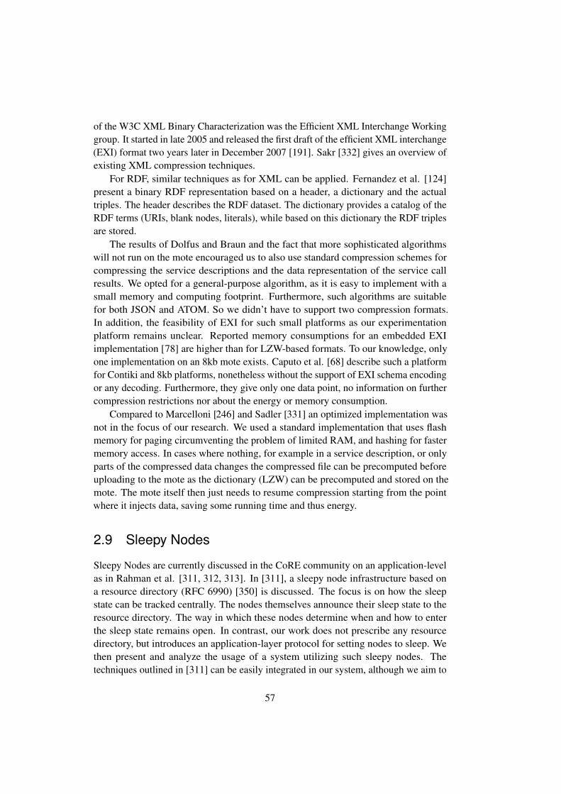
of the W3C XML Binary Characterization was the Efficient XML Interchange Workinggroup. It started in late 2005 and released the first draft of the efficient XML interchange(EXI) format two years later in December 2007 [191]. Sakr [332] gives an overview ofexisting XML compression techniques.
For RDF, similar techniques as for XML can be applied. Fernandez et al. [124]present a binary RDF representation based on a header, a dictionary and the actualtriples. The header describes the RDF dataset. The dictionary provides a catalog of theRDF terms (URIs, blank nodes, literals), while based on this dictionary the RDF triplesare stored.
The results of Dolfus and Braun and the fact that more sophisticated algorithmswill not run on the mote encouraged us to also use standard compression schemes forcompressing the service descriptions and the data representation of the service callresults. We opted for a general-purpose algorithm, as it is easy to implement with asmall memory and computing footprint. Furthermore, such algorithms are suitablefor both JSON and ATOM. So we didn’t have to support two compression formats.In addition, the feasibility of EXI for such small platforms as our experimentationplatform remains unclear. Reported memory consumptions for an embedded EXIimplementation [78] are higher than for LZW-based formats. To our knowledge, onlyone implementation on an 8kb mote exists. Caputo et al. [68] describe such a platformfor Contiki and 8kb platforms, nonetheless without the support of EXI schema encodingor any decoding. Furthermore, they give only one data point, no information on furthercompression restrictions nor about the energy or memory consumption.
Compared to Marcelloni [246] and Sadler [331] an optimized implementation wasnot in the focus of our research. We used a standard implementation that uses flashmemory for paging circumventing the problem of limited RAM, and hashing for fastermemory access. In cases where nothing, for example in a service description, or onlyparts of the compressed data changes the compressed file can be precomputed beforeuploading to the mote as the dictionary (LZW) can be precomputed and stored on themote. The mote itself then just needs to resume compression starting from the pointwhere it injects data, saving some running time and thus energy.
2.9 Sleepy Nodes
Sleepy Nodes are currently discussed in the CoRE community on an application-levelas in Rahman et al. [311, 312, 313]. In [311], a sleepy node infrastructure based ona resource directory (RFC 6990) [350] is discussed. The focus is on how the sleepstate can be tracked centrally. The nodes themselves announce their sleep state to theresource directory. The way in which these nodes determine when and how to enterthe sleep state remains open. In contrast, our work does not prescribe any resourcedirectory, but introduces an application-layer protocol for setting nodes to sleep. Wethen present and analyze the usage of a system utilizing such sleepy nodes. Thetechniques outlined in [311] can be easily integrated in our system, although we aim to
57

use semantic technologies to describe the sensor network, as well as its services andresources.
Allocating tasks to computing nodes is a lively research field. The main streamis centralized approaches versus self-organizing. Kuorilehto et al.[220] provide acomprehensive overview of both. The windowing algorithm that we use later on toevaluate the sleepy nodes implementation is part of the centralized family.
Another research stream focuses on minimizing energy consumption while main-taining partial [112] or full coverage [164, 383] of a specific area, often with a givendegree of redundancy. These approaches differ from ours as we are not just monitoringan area. Moreover, they raise an alarm when specific conditions are met but run abusiness logic that is often only interested in the state of a given monitored entity ata given point in time. Similar ideas as in our approach have been implemented in thedynamic sleep scheduling protocol (DSSP) [66]. DSSP focuses on dense networks andmaintaining coverage. In our approach, we assume that more information about up-coming events is available as part of a centralized business logic or enterprise resourceplanning (ERP) system and, therefore, that it outweighs the benefits of a non-centralizedapproach.
2.10 Services
Service-oriented systems are the glue that keeps nowadays enterprise systems and theInternet running. We will have a closer look into services in general and services in theInternet of Things in particular in Chapter 3 and Chapter 4. When talking about the”Enterprise”-world and the ”Internet”-world, interestingly, both worlds are getting closerand closer. In practice, three major classes of services can be distinguished: legacyenterprise services, SOAP-based services and RESTful services. Traditionally, theenterprise domain had its own service architectures based on technologies such as BAPIand CORBA. They are still in use today, but are considered a legacy. Later on, XML-based web service descriptions and protocols became predominant in the enterprisesector. Meanwhile, on the Internet, the REST paradigm is becoming increasinglypopular. More recently, there seems to be a convergence towards REST services even inthe enterprise. REST services started to supersede SOAP-based services and traditionalBAPI/CORBA installations. A comparison between SOAP-services and RESTful-services has been performed by Pautasso et al. [295]. In the following, we will brieflydiscuss the service categories.
2.10.1 Legacy Enterprise Services
With the widespread adoption of enterprise IT-systems, especially with the adventof Enterprise Resource Planning (ERP) systems, the integration and interoperabilitybetween systems became one of the major issues for enterprise IT vendors. A separationof concerns by using something like services was considered early on as one of the
58
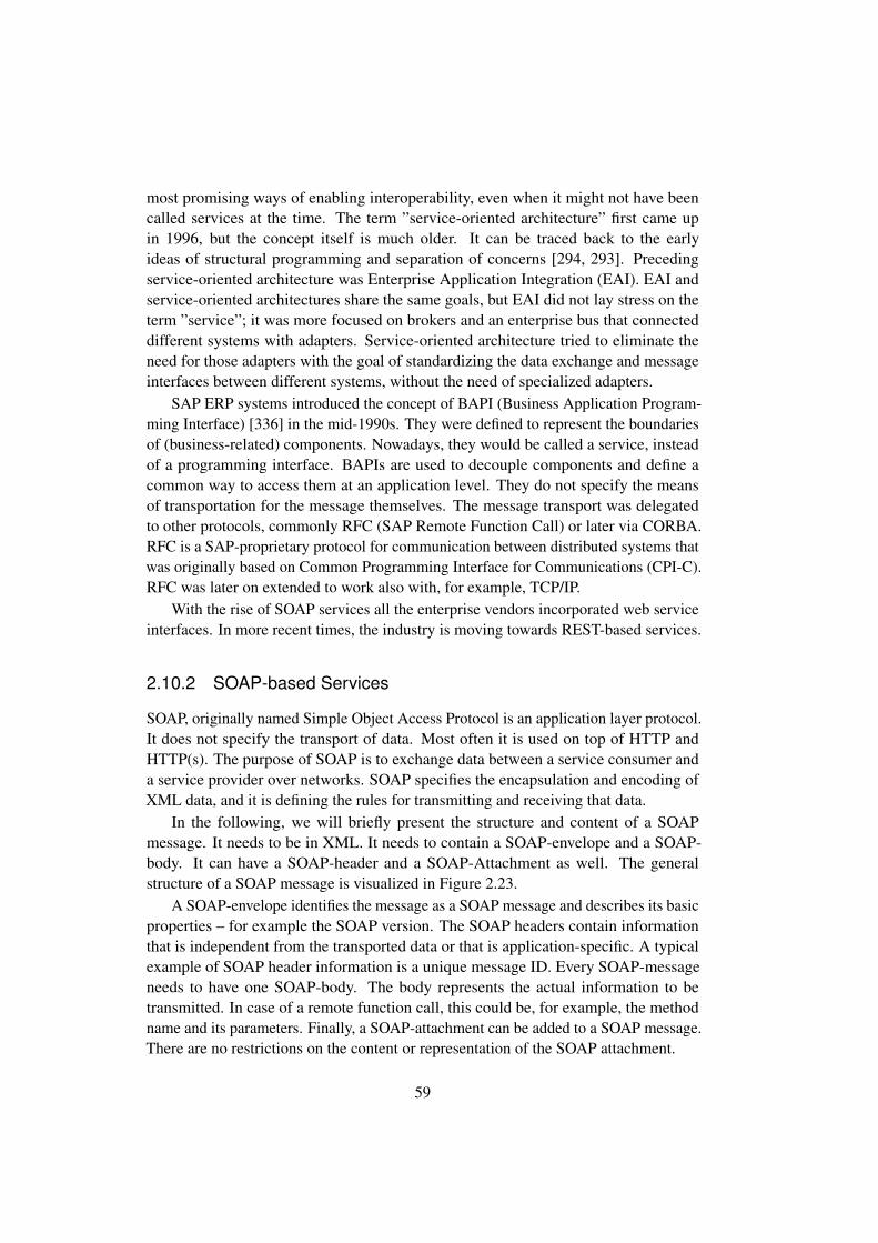
most promising ways of enabling interoperability, even when it might not have beencalled services at the time. The term ”service-oriented architecture” first came upin 1996, but the concept itself is much older. It can be traced back to the earlyideas of structural programming and separation of concerns [294, 293]. Precedingservice-oriented architecture was Enterprise Application Integration (EAI). EAI andservice-oriented architectures share the same goals, but EAI did not lay stress on theterm ”service”; it was more focused on brokers and an enterprise bus that connecteddifferent systems with adapters. Service-oriented architecture tried to eliminate theneed for those adapters with the goal of standardizing the data exchange and messageinterfaces between different systems, without the need of specialized adapters.
SAP ERP systems introduced the concept of BAPI (Business Application Program-ming Interface) [336] in the mid-1990s. They were defined to represent the boundariesof (business-related) components. Nowadays, they would be called a service, insteadof a programming interface. BAPIs are used to decouple components and define acommon way to access them at an application level. They do not specify the meansof transportation for the message themselves. The message transport was delegatedto other protocols, commonly RFC (SAP Remote Function Call) or later via CORBA.RFC is a SAP-proprietary protocol for communication between distributed systems thatwas originally based on Common Programming Interface for Communications (CPI-C).RFC was later on extended to work also with, for example, TCP/IP.
With the rise of SOAP services all the enterprise vendors incorporated web serviceinterfaces. In more recent times, the industry is moving towards REST-based services.
2.10.2 SOAP-based Services
SOAP, originally named Simple Object Access Protocol is an application layer protocol.It does not specify the transport of data. Most often it is used on top of HTTP andHTTP(s). The purpose of SOAP is to exchange data between a service consumer anda service provider over networks. SOAP specifies the encapsulation and encoding ofXML data, and it is defining the rules for transmitting and receiving that data.
In the following, we will briefly present the structure and content of a SOAPmessage. It needs to be in XML. It needs to contain a SOAP-envelope and a SOAP-body. It can have a SOAP-header and a SOAP-Attachment as well. The generalstructure of a SOAP message is visualized in Figure 2.23.
A SOAP-envelope identifies the message as a SOAP message and describes its basicproperties – for example the SOAP version. The SOAP headers contain informationthat is independent from the transported data or that is application-specific. A typicalexample of SOAP header information is a unique message ID. Every SOAP-messageneeds to have one SOAP-body. The body represents the actual information to betransmitted. In case of a remote function call, this could be, for example, the methodname and its parameters. Finally, a SOAP-attachment can be added to a SOAP message.There are no restrictions on the content or representation of the SOAP attachment.
59

Transport Header
SOAP Envelope
SOAP Header
Header Block
Header Block
SOAP Body
Body sub-element
Body sub-element
SOAP Attachment
Figure 2.23: SOAP message
The SOAP specification [147] is rather large. An overview is given, for example,by Mitra et al. [275] or Weerawarana et al. [396].
2.10.3 REST WEB APIs
REST-based services and RESTful services are dominating the Internet nowadays.According to the ProgrammableWeb index [307] four times more publicly availableAPIs are using REST than SOAP. The degree of RESTfulness varies though. Forexample, quite some services ignore the hypermedia aspect of the RESTful paradigm.This caused a controversy in the community, leading to proposals such as introducing amaturity model for RESTful APIs; or of calling those services that do not 100% complywith the RESTful-paradigm as just Web APIs or REST-like APIs. The maturity modelof Leonard Richardson [318] consists of four maturity levels:
0. • Uses XML-based RPC or even SOAP• HTTP, often only one verb• Uses only one address to access the service
1. • Uses different URIs• Uses different Resources• HTTP, often only one verb
2. • Uses verbs according to their HTTP meaning• Uses HTTP result codes• Uses different Resources• Uses different URIs
3. • Uses HATEOS for navigation• Uses verbs according to their HTTP meaning• Uses HTTP result codes• Uses different Resources
60
• Uses different URIsStrictly speaking, the term RESTful can only be applied to Level 3. Many existing
Web APIs that call themselves RESTful are on Level 2 or Level 3, or somewherein-between. Level 0 and Level 1 were mainly important in the beginning of REST erawhere many RESTful APIs were just RPC using (one) HTTP verb.
2.11 Service Descriptions
In the following, we will discuss related approaches for semantically describing andannotating services. As Chapter 3 will discuss in more detail, ”service” is a heavilyoverloaded term. For the following discussion it is important to know that our definitionof service is more throughout and does not only include what we call the technicalinterface. A service is not only what is (technically) accessed and how, but also whointeracts with whom from a business point of view, what Quality of Service attributesare attached to it, and so on. Most of the approaches discussed here are only concernedwith the technical aspect of accessing a service and describing its inputs and outputs;they are less concerned with the underlying high-level concepts.
2.11.1 Semantic Annotations for WSDL and XML Schema
The Semantic Annotations for WSDL and XML Schema (SAWSDL) [212] are a W3Crecommendation [120] for semantical annotation of XML-schemas in general andWSDL 2.0 in particular. WSDL describes a Web service on a purely syntactic level:WSDL species the messages format and what operations can be performed. It does notspecify any meanings of the messages or what the operations mean.
SAWSDL introduces several attributes and seeks to extend WSDL. Those exten-sions are used to annotate interfaces, operations, and parameters. SAWSDL is verygeneric in its use. It defines three attributes: modelReference, liftingSchemaMapping,and loweringSchemaMapping [212]. They can be seen as reference annotations andtransformation annotations [391].
The modelReference attribute may, by specification, be used with every element inWSDL. Nonetheless, it specifies only its use as the semantic annotation of interfaces(wsdl:interface), operations (wsdl:operations), and faults (wsdl:fault). As well as of themore general elements: xs:element, xs:complexType, xs:simpleType and xs:attribute.
The modelReference references the semantic concept behind those elements. Ithas the very generic purpose of referring from a WSDL element to a semantic concept.SAWDSL does not use or recommend any ontology of its own. While the modelRef-erence identifies the concept to which the XML data can be lifted, the liftingSchemadefines how the lifting can be done. The loweringSchema, on the contrary, can be usedto lower the data again from an ontological level to its XML representation.
SAWSDL is one of the early works in semantic modeling of services and it hasinfluenced all future approaches. Compared to Linked USDL, it does not describe
61
services in particular, but mainly technical interfaces in terms of ”how to access theservice”. It does not provide a basic vocabulary for services and it is solely based uponWSDL. SAWSDL follows a conservative approach: It is not the service describing thetechnical interface, but the technical interface describing the service. The modelRefer-ence attribute was probably the most influential. It has been reused several times – forexample, for iService [298], a linked services publishing platform. It definitely influ-enced Linked USDL with the idea of referencing from one element to the other. OWL-S[249], a more advanced approach that we will discuss in Chapter 2.11.2, supports amodelReference based grounding [252]. ModelReference strongly influenced OWL-Sand all its grounding schemes, which in the end, are not more than specializations ofthe modelReference concept. ReLL [9] knows a reference tag and SA-REST [355, 229]is largely based on the SAWDSL idea.
2.11.2 OWL-S
Web Ontology Language for Web Services (OWL-S) is an OWL based ontology fordescribing web-services. OWL-S can be divided into three main parts: a service profile,a service model and a service grounding. We will briefly discuss these three parts.
Service Profile: The service profile is mainly used to allow service advertising anddiscovery. The service profile contains a human-readable description of theservice. Furthermore, it can specify functional aspects of a service as input/out-put/precondition/effect (IOPE) specification.
Service Model: The service model describes a service as a process model. It de-scribes a service operation in terms of what a service consumer can do and when.Furthermore, it can describe the composition of one or more services.
Service Grounding: The service grounding describes the necessary means to call aservice – for example, regarding the message format and its protocols. The focuson the service grounding is on describing WSDL services.
OWL-S is comparable in terms of its goals with Linked USDL. Nonetheless, itlacks the business part of Linked USDL and also has not the focus of linking ontologiesand lightweight REST-based services as we will use throughout this work. Rather, it isconcerned with heavyweight XML/WSDL-based services.
2.11.3 Web Service Modeling Ontology
The Web Service Modeling Ontology (WSMO) is a framework for the semanticaldescription of web services. It is based upon the Web Service Modeling Framework.WSMO, as a framework, consists of the following four elements [111]: ontologies thatdefine the formal domain knowledge; Web Service descriptions that define the objectivesof the service consumer; goals that define the objective of the service consumer; and
62
mediators that enable the interoperability and handling of heterogeneity between datastructures and processes.
2.11.4 Web Application Description Language and the Semantic Bridgefor Web Services
The the Web Application Description Language [154], commonly known as WADL,was developed by Sun Microsystems as a RESTful counterpart of the SOAP-basedWSDL. The goal of WADL is to technically describe a ReST-service in the same wayas WSDL describes a web service. WADL models the resources provided by a serviceand the relations between them. In WADL each resource is described as a requestbased on an HTTP method, its required inputs and the provided responses. WADLonly specifies the technical interface and the data encoding, not its meaning. It wasnot designed for semantic interoperability, and it does not provide placeholders forsemantic references of the operations, parameters, and results. The Semantic Bridgefor Web Services (SBWS) [32] tries to fill this gap and allows adding semantics to theinput and output of a REST method similarly to SAWDSL with modelReference-likeproperties. It wraps service operations described by a WADL document to create aSPARQL endpoint describing those services.
WADL differs from our approach first because it is not a semantic approach. Itmereley describes a technical interface. Furthermore, it is bound to HTTP while we areaiming at any RESTful technology, including the Constrained Application Protocol asintroduced in detail in Chapter 6. WADL is typically perceived as rather complex and ithas not gained widespread use.
2.11.5 Semantic Annotations for REST
Semantic Annotations for REST (SA-REST) [355, 229] is based on SAWDSL. Nonethe-less, its approach in the use of annotations is different. Most of the semantic annotationsare used to annotate an already existing technical description of a service, for exampleWSDL and – on-top of that – to add semantic information. SA-REST annotations areadded to the services described in (human-readable) HTML pages. SA-REST usesRDFa [3] to make this information machine-readable.
2.11.6 HTML for RESTful Services
HTML for RESTful Services (hRESTS) [211] follows a similar approach as SA-REST.Instead of using RDFa, however, it uses microformats [49]. The purpose of the hRESTSis to provide a machine-readable representation of common web services and APIdescriptions embedded into human-readable HTML. Microformats, in general, takeadvantage of existing (X)HTML facilities (e.g. the class and rel properties) to annotatethe interesting parts of a human-readable API description. hRESTS defines seven
63

classes which can be used to annotate a web page. Namely: service, operation, address,method, input, output and label.
2.11.7 MicroWSMO
MicroWSMO [210, 209, 130] is a SAWDSL-like extension used to semantically an-notate RESTful services based upon hRESTS. MicroWSMO supports model (sameas modelReference), lowering and lifting. Those can be attached to any hRESTSsservice property to specify the mapping between semantic data and its technologicalrealization.
2.11.8 Resource Linking Language
Resource Linking Language (RELL) [7, 9] introduces a metamodel for REST servicesand a service description based on a meta model. The meta model formally definesa service as a set of resources. Every resource is associated with different properties,such as a unique identifier, a name and a URI pattern. ReLL descriptions are XMLdocuments created according to the ReLL schema. ReLL is not specifically designed forthe Internet of Things, however; it is more focused on XML and the use of XML-relatedtechnologies, such as XPATH and XSLT. Based on these technologies the authorspresented a crawler [8] that can access the resources described in ReLL and transformthem into RDF.
ReLL shares some similarities with Linked USDL and Linked USDL for IoT,mainly its lightweight design principles and our endpoint descriptions, as will be shownin Chapter 5, in the sense that we also build upon URI patterns.
2.11.9 RESTdesc
A recent approach to semantically describe RESTful service is RESTdesc [389, 388]. Itis an RDF based notation of a service, written in N3. Thus, it is similar to Linked USDLand OWL-S. RESTdesc, other than Linked USDL, is closer to the actual RESTfulinterface. It was designed to perform reasoning on the interface. It models technicalservice interfaces not in terms of resources and operations, but as functional descriptions.The functionality is expressed as preconditions that when fulfilled will yield somepostconditions. A RESTdesc service consumer can define a certain goal and RESTdescin combination with a reasoner can deduce the series of REST operations that will resultin the specified goal. RESTdesc has been applied in the Internet of Things domain[217].
2.11.10 Semantic RESTful Data Services
Semantic RESTful Data Services (SEREDASj), introduced by Lanthaler and Gtel[227, 225, 224], is a service description language for describing the syntactical and
64
semantical aspects of RESTful services. SEREDASj was specifically designed withJSON as data representation. A SEREDASj service description consists of two sections:a metadata section and an element section. The metadata section describes prefixes andrelationships between resources. The element section describes the structure of the datarepresentation. Both sections can contain references to other ontologies to semanticallydescribe the elements.
2.12 Integration: Internet of Things and Web of Things
In the following we will discuss three different streams of integration of IoT or WSN ser-vices into enterprise systems or into the web at general. The first stream is XML/SOAP-based integration techniques. The second one, which we will summarize as Web ofThings Integration, contains RESTful approaches. At a higher abstraction level we willalso briefly discuss integration based upon business process modeling.
2.12.1 Web-Service based Enterprise Integration of WSNs
An approach that shares similar goals as our research has been performed by Glombitzaet al. [140, 139]. This was based on the observation that most enterprise IT systemsat that time used SOAP-based webservices as the main means to implement service-oriented architectures. To allow a seamless integration of sensor networks into theEnterprise world, Glombitza et al. investigated how webservices can be made availableon single sensor nodes. However, the solutions that have already were availablecould not be directly downscaled to wireless sensor nodes due to resource constraints.This problem was solved by suggesting a novel transport protocol [141] as well asa new SOAP-transport-binding [140]. To support seamless integration and to enablecommunication between systems that do not both are able to communicate via thisspecialized protocol and binding an automatic webservice binding conversion [139]has been developed. Glombitza et al. also did some work business process integration,which we will discuss in Chapter 2.12.3
A second approach was put forward by Spiess et al. [363]. They suggested anarchitecture for integration Internet of Things devices into enterprise systems. Similarlyto Glombitza et al. they suggest to use SOAP and, furthermore, the full stack of WS-*protocols. The focus of their work was more on device and service management as awhole and not that much on the actual integration of the devices. They assume thatIoT-devices are either capable of running a SOAP protocol or not. In the latter case, theysuggest the use of a middleware that translates SOAP messages to whatever protocolthe device supports and vice versa.
We share the goals of Glombitza and Spiess. We can leverage on their ideas, butwe are taking a different approach to achieve the integration. We see and foresee atrend towards RESTful systems, also in the enterprise world. The current generation,and even more the next generation, of business modeling tools and enterprise tools
65
in general will support RESTful systems. This new trend is best illustrated with thestandardization efforts of the RESTful OData protocol that is being driven by all themain enterprise vendors.
A second main differentiator is that the web-service based approaches did not hadsemantic descriptionability in the focus of their work. Both are based on traditionalWSDL-based webservices. Both works could, of course, be appended by using one ofthe WSDL/XML based techniques discussed in Chapter 2.11.
2.12.2 Web of Things Integration
Similar to the Web-Service based approaches discussed in Chapter 2.12.1 there hasbeen work done on (enterprise) integration based on RESTful architectures. Commonly,those are referred to as the Web of Things [150], because the main goal of this stream ofresearch was to make things accessible through the web. The web of things is advocatedas a refinement of the Internet of Things by integrating smart things not only into theInternet (the network), but into the Web (the application layer) [150, 151, 153, 148].The Web of Things advocates the use of RESTful web services. Regardless of the kindof device, to be a member of the Web of Things it has to offer its API over a RESTfulweb service. Therefore, the web of things can be defined as [330]:
The WoT enhances physical objects with a virtual counterpart representingthe latter in the virtual world. In contrast with the IoT, the WoT mandatesthe strict application of RESTful principles to its APIs.– Ruppen, 2015 [330]
From a technical point of view we are considering constrained devices way morethan the WoT movement does. The latter is largely concerned with being able to use thefull ”web-stack”. We share with them the vision of REST-based access to IoT devices.
2.12.3 Process-based Integration
Integration into workflow and business process management is important when talkingabout enterprise integration from a business point of view. Graphical modeling toolssuch as BPEL [285] and BPMN [397] allow business specialists, who are not reassur-ingly software developers, to create workflows that can run to fulfill a business goal.Our work is focused on the service aspects of enterprise integration and leveraging onsemantically enriched services. It has to be integrated with a business process approachas presented by Meyer et al. [264]. The IoT-BPMN integration presented by Meyeret al. was developed in the same research project as the work presented here and theycan complement each other. We will first discuss the approach of Meyer et al. and alsodiscuss related work from Glombitza et al. [138] based upon web-services, as wellas Caracas et al. [71]. The three works all try to solve the same problem, but withvery different means. Meyer et al. introduce IoT modeling concepts and base their
66
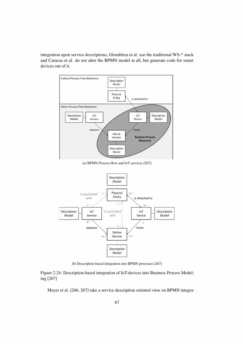
integration upon service descriptions, Glombitza et al. use the traditional WS-* stackand Caracas et al. do not alter the BPMN model at all, but generate code for smartdevices out of it.
source hosted on an IoT device that performs the actual deployment responsibility
and according to Fig. 1 has the relation „is exposed“ to the process task.
As summarized by Fig. 2, two out of four main components of the IoT Domain
Model fall in the perspective of business process resources: the IoT device and the
native service. For both components description parameters can be specified applying
the description of model of [5], which is relevant for the process resolution and execu-
tion. The BPMN 2.0 notation basically supports two ways to represent resources in
the process model: one, on activity-level and one, on cross-activity-level. In the fol-
lowing we will apply both of these options to the IoT domain model.
Fig. 2. Classification of IoT components in business process view
4 IoT Devices and Natives Services as Process Resources in
BPMN
In this section, we propose a specification of the IoT device and its native software
components as an extension to the BPMN 2.0 notation. When integrating the identi-
fied business process resources of the last section to BPMN, we face two main chal-
lenges. First, an IoT device and its native service are usually not considered and there-
fore they are not mentioned in the specification. The reason for this is that one central
ERP system is often assumed to automate all enterprise business processes without
including millions of distributed and connected devices, all coming with the capabil-
ity to directly overtake execution responsibility. Second, we have to deal with two
types of process resources on different levels at the same time, the IoT device and its
hosted native services being exposed by an IoT service. Usually the BPMN 2.0 stand-
ard considers different roles of resources, but not two completely different types on
(a) BPMN Process-flow and IoT services [267]
provide information to the IoT services and on the other hand they may obtain infor-
mation from the IoT services that allows for performing certain physical actions. Be-
tween an IoT device and the digital representation of a physical entity the artificial
relationship “attached to” is created, so that the physical entity becomes part of the
digital world through using an IoT device. Properties of the entity can in consequence
be measured or changed by the IoT device.
Continuing to integrate the view of the information model of [13] with respect to
the defined specification models, there is the possibility to assign each major compo-
nent to a knowledge base that defines describing information in a structured form, and
expresses their logical relations to one another. Ontologies are usually applied to de-
scribe an existing knowledge base. As part of the process model, however, it is suita-
ble to use the same ontologies to formulate requirements for individual elements of
the process model as they are used for the process resolution phase- the actual alloca-
tion of process elements. For instance, for this replaceable description model the
OWL definitions of [5] or the USDL definition of [15] might be applied.
Fig. 1. Business process relevant IoT domain components (own presentation based on [13] and
[5])
3.2 Resource Perspective
This section includes mapping the identified, modeling relevant IoT components of
the last section to the typical available components that are provided by business pro-
cess modeling notations. Here we focus on the identification of the components as
process resources. For this general part we don’t focus explicitly on the BPMN 2.0
notation, even though some components are not available in other modeling notations.
(b) Description based integration into BPMN processes [267]
Figure 2.24: Description-based integration of IoT-devices into Business Process Model-ing [267]
Meyer et al. [266, 267] take a service description oriented view on BPMN integra-
67

tion. As shown in Figure 2.24, they identified services as one of the main componentsthat can be used as process resources and, thus, modeled by the business specialist.They propose, to make BPMN IoT-aware to not only use the facilities already includedin BPMN, but a specification of the IoT device and its native software components asan extension to the BPMN 2.0 notation [267].
Glombitza et al. developed, a workflow management system [138, 142] based ontheir work on web services. The system allows transparent execution, monitoring andoptimization of business processes. It aims for being used directly by the business expert.In [138], they propose a language called Graphical Workflow Execution Language forSensor Networks (GWELS). Its objective is the creation of a link between the worldof WSNs and enterprise IT systems. GWELS issues a series of service calls, basedupon a workflow graph. Furthermore, they introduced a state-machine approach anddomain-specific language for model driven development [142]. The goal of the statemachine approach was, similar to the GWELS approach, to model application logicgraphically.
A different approach has been suggested by Caracacs et al. [71]. They argue thatneither the syntax nor the semantics of BPMN needs to be changed. WSN interactionsare modeled solely using BPMN events and BPMN sequence flows. They use BPMNsub-tasks that can map to an API call on the target device – for instance, the wirelesssensor node. Instead of calling services that already run on the sensor device they thencompile out of the model the necessary code for the sensor node and upload a newassembly.
2.13 Summary
In this chapter we briefly introduced the main technologies and concepts used in thiswork. We are using two hardware platforms (IRIS and Waspmote Pro, see Chapter2.1), both based on a 2.4 GHz radio using the IEEE 802.15.4 MAC layer protocol. Wewill later on leverage on two differences between Waspmote Pro and IRIS: WaspmotePro is the more advanced platform. It features a more precise real-time clock and anadditional very-low energy sleep mode. Our software stack mainly consists of the MoteRunner environment, as introduced in Chapter 2.2. Mote Runner is a virtual machinebased software platform for running IoT applications. It is purely reactive and thusnot have any concurrency mechanisms (e.g. threads). We also introduce the essentialparts of MRv6 (Chapter 2.3.3) – Mote Runners implementation of 6LoWPAN (Chapter2.3.2).
On the architectural side a basic understanding of RESTful architectures is necessary(see Chapter 2.4). We introduced RDF and OWL as modeling languages. Furthermore,we introduced related work in the area of semantic services and enterprise integration.We showed how a service description language integrates into process models. Wemainly refer to the work of Meyer et al. [267], which was designed with semanticservice description based enterprise integration in mind.
68

Part II
Service Architecture forEmbedding IoT-services into
Enterprise Environments
In the second part of this work we present conceptual and architectural work onsemantics-aware enterprise IoT-integration. In Chapter 3 we discuss the concept of anIoT-service. We present a literature survey on previous definitions and the use of theterm service in the IoT in general. We contribute our own definition and classificationof IoT service. Chapter 4 discusses the special needs of enterprises with regard toIoT-services. We present a novel architecture based on distributed Linked Services. Wewill argue that distributed Linked Services integrates well into both enterprises andIoT-systems. Furthermore, we will present a concept for easing modeling of businessprocesses in a semantics-aware enterprise.

70

Chapter 3
Services and the Internet of Things
In enterprises, the terms ”service” and ”service-oriented architecture” are key concepts[380, 56, 35, 259]. In this chapter, we argue, based on a literature survey [381, 259], thatno common definition of IoT service exists. We contribute to an overall understandingof the IoT-domain by deriving a definition and classification of IoT-services. We embedservices in a comprehensive IoT domain model — the IoT-A model — and describe itsrelationship to other modeling elements of this domain model. Our understanding ofthe term ”service” and the differences with other concepts, like a technical interface,will be used in all subsequent chapters.
3.1 Introduction
As part of our work on actuator and sensor integration into enterprise IT systems, weidentified services as one of the main building blocks of the future Internet. Surpris-ingly, there is still no common nomenclature and the term ”IoT-Service” has differentmeanings in different works [381]. As most enterprise software solutions nowadaysare written following a service-oriented approach a convergence of the Internet ofServices (IoS) and the enterprise IT world is anticipated for describing and provisioningIoT-services. Therefore, it is a necessity to have a good understanding of what anIoT-Service is, what its relationships to existing concepts are and how these conceptscan be brought into the IoT world.
This chapter will first describe services in general and as a main building block ofthe Internet of Things. Furthermore, we will survey existing definitions of services inan IoT-context and later present our own coherent classification [380, 259]. In addition,we will show how this abstraction can help a business domain expert in working withIoT-services.
71

3.2 Services
Services are a suitable abstraction for building complex software systems. They arethe fundament of most of today’s enterprise systems [399]. In the same way that theyplay a crucial role in nowadays IT-systems, it is suggested that they will also play acrucial role in the Internet-of-Things [152]. Services are a central part of many domainand reference models, including the IoT-A architecture. Furthermore, currently a lot ofresearch is being carried out in the areas of IoT and services [18].
Nonetheless, ”service” is a somewhat overloaded term that can have many meanings.For example, one wide-spread use of the term service is to use it as a synonym for whatwe call a technical interface that is software functionality provided by a defined serviceinterface (e.g. Web-Services). Barros and Oberle [29] define a service as:
a commercial transaction where one party grants temporary access to theresources of another party (...)— Barros and Oberle, 2012 [29]
In service science and in Internet of Services (IoS) research there were and aremany efforts to establish a single definition of the term ”service”. A comprehensivediscussion of several ways to define service is given by Ferrario [125]. However, nodefinition has been accepted by the wider community yet [190, 29, 125].
3.3 Survey on the term ”Service” in IoT
To get a clearer picture of what is currently considered an IoT-Service, we surveyedseveral publicly funded projects (e.g. SIRENA [51], SOCRADES [152], SENSEI [173],RUNES [97], and OASiS [284]) and did a comprehensive search through the ACM andIEEE literature databases for service concepts in the realm of the Internet of Things,Web of Things (WoT), cyber-physical systems (CPS), and related terms.
Only publicly available material was used. For example, no internal reports weretaken into consideration. The search returned more than 620 documents that had a highprobability of being of interest. These documents were automatically downloaded, afull-text layer added if needed (tessaract and hocr2pdf), analyzed with a full-text searchengine (pdfgrep) and ranked according to their likelihood of discussing services andservice-oriented concepts using a weighted mean algorithm based on selected keywords.The process is depicted in Figure 3.1. Out of all papers taken into consideration mostpapers were in the realm of the Internet of Things (≈52%), followed by Cyber-PhysicalSystems (≈40%).
A vast majority of the selected papers used or mentioned service-oriented principles(>90%). This is not a surprise since we were searching for service-related papers.What is surprising, however, is that only very few papers and projects dealing withIoT-services defined precisely what they consider an IoT-service (<10%), how it differsfrom traditional services, and how to combine IoT and non-IoT services. This is
72

Document Selection
Document storage
Text processing (Tesseract)
Document storage (searchable)
Word list and count DB
Parse text and count words
(pdfgrep) Keyword weighting
Result set
Evaluation
A
A
A
M
M
Figure 3.1: Survey: Process
even more astonishing since there are many IoT-middleware and IoT service orientedframeworks that claim to bridge the gap between the Enterprise SOA world and thephysical world. Mainly papers from the realm of IoT dealt with SOA or services.This can be explained by a slight bias towards the term ”Internet of Things”, as itsmainly used by European projects. Furthermore, CPS is typically more directed towardsreal-time systems [230] than IoT is; therefore CPS is less often used in a service context.Most papers (≈ 80%) had only an implicit definition of IoT-service, or gave just ageneral definition of service.
In the following, we will focus on summarizing the key findings with regard toservices. In a technical sense, there are differences between traditional services and IoT-services, like special QoS-parameters and the fact that the devices running these servicesare often resource-constrained with respect to computing, storage, communication, andenergy capabilities. Many works focus on dealing with the special characteristics ofsuch systems. Furthermore, IoT services might only occasionally be connected to anetwork [156, 194]. The findings generally are inline with a comprehensive survey onthe IoT in general, carried out by Atzori et al. [18]. Atzori et al. also noticed a tendencytowards service-orientation. Nonetheless, IoT services are not explicitly covered bythem.
From all the mentions of the term service, only a few definitions go beyond atechnical interface. In the end, we were only able to identify three specific definitionsthat particularly concern what we will later call an IoT-service: the terms ”real-world
73

SOA” used by Karnouskos et al. [194], ”real-world service” by De et al. [104], and theterm ”web presence” by Debaty et al. [106]. In the following, we briefly summarizethose definitions:
Karnouskos et al. [194] define the term ”Real-world SOA” as:
Real-world SOA, is a SOA where each device offers its functionality in aservice-oriented way; is able to discover other devices and their hosted ser-vices dynamically at runtime; can invoke actions of the discovered servicesdynamically; and is able to publish and subscribe to typed, asynchronousevents— Karnouskos et al. [194]
However, a specific discussion of what constitutes a real world (or IoT) service ismissing though.
The similar term ”real-world service” is used by De et al. [104]
The Internet of Things envisions a multitude of heterogeneous objects andinteractions with the physical environment. The functionalities providedby these objects can be termed as ”real-world services” as they provide anear real-time state of the physical world.— De et. al. [104]
Nonetheless, the term ”real-world service” is ambiguous as it is also used forexplicitly non-IT services provided in the real world (e.g. the transportation of goods)[5]. This is why we use the term ”IoT-service”, which has no predefined meaning inother domains.
A similar definition is given by Debaty et. al. [106]:
To computer applications, the incarnation of a Web presence is a set ofWeb services to learn and interact with the physical entity. where a webpresence is the virtual representation of a physical entity as an integrantpart of the Web.— Debaty et al. [106]
These are not the only definitions available. For example, some research projects(e.g. [316, 173]) differentiate between sensing and actuation services. Nonetheless,the definitions of these two kinds of services, which are essential for the Internet ofThings, are only implicitly given. For example, when the term IoT-service is used fordescribing interfaces to devices that perform the actual sensing or actuation task.
3.4 Services and the Internet of Things-Architecture
This section shows how we integrated services in the Internet of Things-Architecture.We continue using an intuitive definition of the term ”service”. In Chapter 3.5, we will
74

introduce our definition and a classification of service. We now introduce the Internet-of-Things Architecture (IoT-A), with a strong focus on how we utilized services in thisarchitecture. The IoT-A project started with the perception that even after many yearsof heavy discussion in the community, there was still no clear and common definitionof many concepts. The range of the IoT domain and IoT solutions is already large. Theobjective of the project was not to develop or consider a ”one-size-fits-all” protocol orarchitecture, nor to define interoperability layers between all sorts of devices. The maindriver of the project was the observation that there was a need for a common groundat more abstract levels. The results of the IoT-A project are based on a cooperation ofmore than 20 organizations from industry and academia that have been working for aperiod of more than three years. The overall results of the project can be found in Bassiet al. [34]. In this chapter, we only describe the service-related part that we contributedand how we integrated it into the IoT-A architecture.
IoT-A (257521)
Internet of Things – Architecture © - 58 -
Figure 10: UML representation of the IoT Domain Model.
The instance diagrams such as Figure 5 are concrete instantiations of the IoT Domain Model, i.e. concrete architectures modelled with the concepts of the IoT Domain Model.
Device
Physical Entity
Human User
Service
On-Device Resource
SensorActuator
Network Resource
Resource
User
Passive Digital Artefact
Active Digital Artefact
Virtual Entity
Digital Artefact
Augmented Entity
Tag
Animate objects (humans, animals etc.)
Hardware
Software
Not clearly classifiable (e.g., combination)
Colour Scheme
XOR
0..*
contains
0..1
1
1
0..*
invokes /subscribes
1..*
1..*
represents 1
0..*
has Informationabout / acts on
0..*
0..*
isassociatedwith
0..*
0..*
contains
0..*
0..* identifies
0..10..*
isassociatedwith
0..*
0..*contains
0..1
1
1..*
0..*
contains
0..10..*
exposes
0..*
0..*
interactswith
0..*
0..*
hosts1
0..*
isattachedto
0..*
0..*
reads
0..*
0..*
monitors
0..*
0..*
actson
0..*
Figure 3.2: Relationship between a user and a physical entity [33]
As a part of the Internet of Things-Architecture project, six core concepts of theInternet of Things have been identified [160], namely: user, physical entity, virtualentity, augmented entity, device, resource, and service. The main driver behind anyIoT-system is the user who has the requirement to interact with a so-called real-worldobject. The term user is used in a generic way and does not need to be human. Anytechnical device or technical process can be the user of a system. The real-worldobjects can be passively monitored, or actively manipulated by the user. A physical
75

entity (sometimes just called Entity or Thing) is a real-world object in which a user isinterested.
The term ”physical entity” was mainly used to avoid misunderstandings betweena real-world entity and entities that might exist otherwise, for example, as part of aninformation system. Other works sometimes use the terms real-world object [103, 323],or Entity of Interest [394, 155]. The relationship between a user and a physical entity isshown in Figure 3.2.
The next concept is that of a Virtual Entity: The idea of a virtual entity is closelyrelated to the concept of a virtual counterpart, as introduced by Romer et al [323]. Avirtual entity is the digital counterpart of the physical entity that exists in an informationprocessing system. The third *-entity concept is that of an augmented entity. Anaugmented entity is the composition of a Physical Entity with its associated VirtualEntity. The relationship between the three entity types is shown in the middle of Figure3.2.
Figure 3.3 shows the complete domain model as developed in the IoT-A project.We will now describe how services interact with devices. Devices are computing units(any hardware that is able to do ”something”). In the domain model [33], the device isthe superclass for the more specific components. Devices can be physically attached toPhysical Entities, like an RFID-tag. They can also be somewhere in the surroundingsof a physical entity — for example, a temperature sensor in a container. The threemost common device-types are tags, sensors, and actors. Tags identify physical entities.They can be read by sensors. Sensors monitor physical entities, whereas actors can acton physical entities.
Resources are defined as software components that implement functionalities [34].Resources can be hosted on a device or any other place in the network or in the cloud.A cloud resource, for example, could derive higher level information by analyzing dataprovided by other resources hosted on sensor devices. We will use the term ”resources”for means to get information about the environment. Resources provide the technicallinks to physical entities. They could be more than just ”dumb” sensors. For example,the temperature of a room (the physical entity we are interested in), could be observedby one ore more mobile phones of people who are actually in the room. In this case,the resources are the mobile phones. The resources then access temperature sensors onthe phone. The sensors are the devices.
While resources provide functionality they do not offer any means of accessingthese functionalities. A service exposes the functionality of a resource via an interfacethat can be invoked by the user. The service has internal knowledge on how to access thefunctionality provided by a resource. The definition of a service is technical in natureat this point. In Chapter 3.5, we will generalize this to form a more comprehensivedefinition of an IoT-service. The IoT-A is very generic in nature. It offers manydesign choices to a system designer. For example, it does not specify how services aredescribed, how the interface of the service can be derived, or what kind of physicalentity it interacts with. However, it suggests the use of semantic services.
76

IoT-A (257521)
Internet of Things – Architecture © - 58 -
Figure 10: UML representation of the IoT Domain Model.
The instance diagrams such as Figure 5 are concrete instantiations of the IoT Domain Model, i.e. concrete architectures modelled with the concepts of the IoT Domain Model.
Device
Physical Entity
Human User
Service
On-Device Resource
SensorActuator
Network Resource
Resource
User
Passive Digital Artefact
Active Digital Artefact
Virtual Entity
Digital Artefact
Augmented Entity
Tag
Animate objects (humans, animals etc.)
Hardware
Software
Not clearly classifiable (e.g., combination)
Colour Scheme
XOR
0..*
contains
0..1
1
1
0..*
invokes /subscribes
1..*
1..*
represents 1
0..*
has Informationabout / acts on
0..*
0..*
isassociatedwith
0..*
0..*
contains
0..*
0..* identifies
0..10..*
isassociatedwith
0..*
0..*contains
0..1
1
1..*
0..*
contains
0..10..*
exposes
0..*
0..*
interactswith
0..*
0..*
hosts1
0..*
isattachedto
0..*
0..*
reads
0..*
0..*
monitors
0..*
0..*
actson
0..*
Figure 3.3: IoT-A domain model (complete view) [33]
77
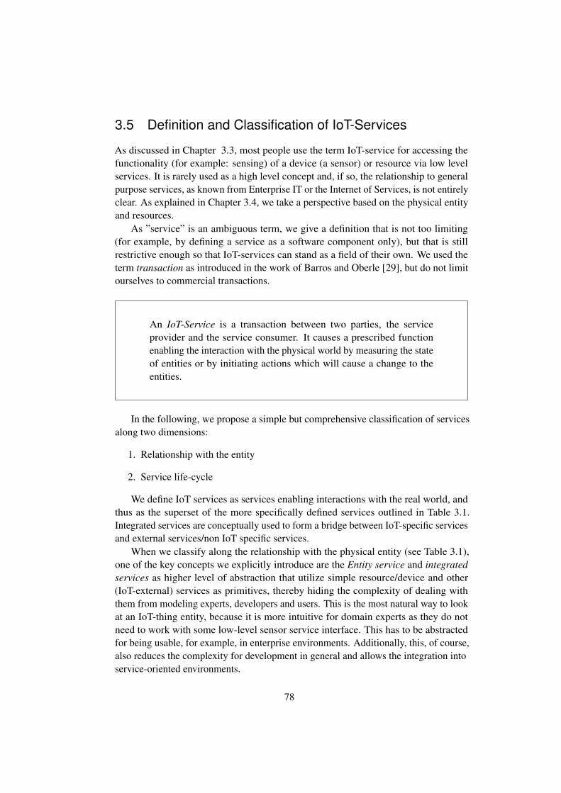
3.5 Definition and Classification of IoT-Services
As discussed in Chapter 3.3, most people use the term IoT-service for accessing thefunctionality (for example: sensing) of a device (a sensor) or resource via low levelservices. It is rarely used as a high level concept and, if so, the relationship to generalpurpose services, as known from Enterprise IT or the Internet of Services, is not entirelyclear. As explained in Chapter 3.4, we take a perspective based on the physical entityand resources.
As ”service” is an ambiguous term, we give a definition that is not too limiting(for example, by defining a service as a software component only), but that is stillrestrictive enough so that IoT-services can stand as a field of their own. We used theterm transaction as introduced in the work of Barros and Oberle [29], but do not limitourselves to commercial transactions.
An IoT-Service is a transaction between two parties, the serviceprovider and the service consumer. It causes a prescribed functionenabling the interaction with the physical world by measuring the stateof entities or by initiating actions which will cause a change to theentities.
In the following, we propose a simple but comprehensive classification of servicesalong two dimensions:
1. Relationship with the entity
2. Service life-cycle
We define IoT services as services enabling interactions with the real world, andthus as the superset of the more specifically defined services outlined in Table 3.1.Integrated services are conceptually used to form a bridge between IoT-specific servicesand external services/non IoT specific services.
When we classify along the relationship with the physical entity (see Table 3.1),one of the key concepts we explicitly introduce are the Entity service and integratedservices as higher level of abstraction that utilize simple resource/device and other(IoT-external) services as primitives, thereby hiding the complexity of dealing withthem from modeling experts, developers and users. This is the most natural way to lookat an IoT-thing entity, because it is more intuitive for domain experts as they do notneed to work with some low-level sensor service interface. This has to be abstractedfor being usable, for example, in enterprise environments. Additionally, this, of course,also reduces the complexity for development in general and allows the integration intoservice-oriented environments.
78
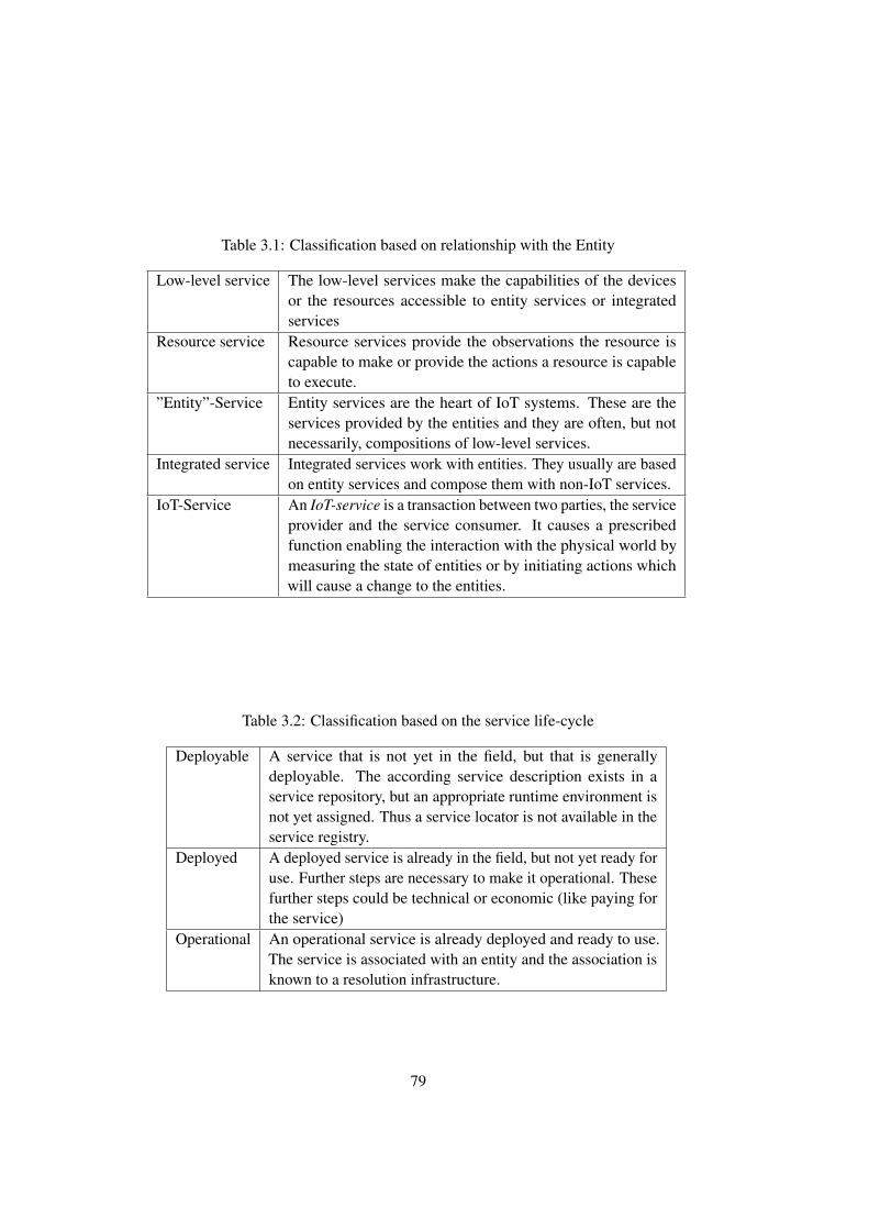
Table 3.1: Classification based on relationship with the Entity
Low-level service The low-level services make the capabilities of the devicesor the resources accessible to entity services or integratedservices
Resource service Resource services provide the observations the resource iscapable to make or provide the actions a resource is capableto execute.
”Entity”-Service Entity services are the heart of IoT systems. These are theservices provided by the entities and they are often, but notnecessarily, compositions of low-level services.
Integrated service Integrated services work with entities. They usually are basedon entity services and compose them with non-IoT services.
IoT-Service An IoT-service is a transaction between two parties, the serviceprovider and the service consumer. It causes a prescribedfunction enabling the interaction with the physical world bymeasuring the state of entities or by initiating actions whichwill cause a change to the entities.
Table 3.2: Classification based on the service life-cycle
Deployable A service that is not yet in the field, but that is generallydeployable. The according service description exists in aservice repository, but an appropriate runtime environment isnot yet assigned. Thus a service locator is not available in theservice registry.
Deployed A deployed service is already in the field, but not yet ready foruse. Further steps are necessary to make it operational. Thesefurther steps could be technical or economic (like paying forthe service)
Operational An operational service is already deployed and ready to use.The service is associated with an entity and the association isknown to a resolution infrastructure.
79

Another important classification of services is according to the service lifecycle.Apart from the different Quality of Information (QoI) and Quality of Service (QoS)constraints of IoT-services, the other very special thing is that they are bound to andrun on a large variety of devices, and they have to be aware of physical entities. Thiscomplicates the service management compared to traditional service managementframeworks. In an Enterprise context, it is therefore a necessity to have a closer lookat the different states in the service lifecycle: This is a necessary precondition forthe service management, as well as for enterprise service orchestration and servicechoreography engines as discussed by Haller et al. [157] and Sperner et al. [362].An IoT-service is usually bound to a physical entity and working together with aservice environment or within a general service ecosystem. In general, we distinguishbetween three different states: deployable, deployed and operational. We call a servicedeployable, if it is generally ready to be deployed in the field. Commonly, this meansthat the service is either not yet on its destination or not yet part of an appropriateservice runtime environment as part of the service ecosystem. Once the service is in thefield (i.e. at its target destination), we call it deployed. A deployed service is not yetworking and serving requests. Further steps might be necessary. These steps can beeither technical or economic. This could mean that first batteries need to be charged tobecome operational or that it is waiting for someone to pay for its services. Finally, wecall a service operational if it can serve requests. The service is typically associated toa physical entity and is known to a service ecosystem, that means it can be found in aservice repository and resolved to a technical endpoint.
3.6 Conclusions
The term ”IoT-service” is used inconsistently in literature. Most projects use the termintuitively. While it might sound obvious that there are specific differences betweenservices in a classic sense and services that allow interaction with the physical world,a conceptual frame defining them is necessary. First, in Chapter 3.2, we argued thata comprehensive definition of the term ”service” in the Internet of Things is needed.In Chapter 3.3 we performed a literature survey and concluded that many works arebased on a rather implicit definition of service and that no generally accepted definitionexists. In Chapter 3.4 we then showed how services interact within an IoT framework.We introduced a conceptual view on IoT-services, which allows easy integration ofIoT entities into the service-oriented world. Based on existing definitions, in Chapter3.5, we suggest a definition based on the term ”transaction” that is consistent withdefinitions found in service science. The classification and the surrounding conceptsare centered on the entity and not that much on the technical representations or meansof realization through low-level services. We explained the entity-concept and mappedour service-definitions to it. In the next chapter, we will discuss how those entities andservices can be integrated into enterprise IT systems.
80

Chapter 4
Enterprise-embedded IoT-Services
This chapter discusses the special needs of enterprises with regard to IoT-services.We present the opportunities for an enterprise that lie in the general use of semanticsand service descriptions for interoperability [381, 375, 382, 373, 374]. We contributeabstractions — such as — the semantical physical business entity [382] to enable busi-ness modeling using semantic concepts. Furthermore, we present a novel architecturebased on linked service descriptions to enable interoperability with IoT-devices. Itsnovelty is the combination of Linked Services and the distribution of services, whichcombined, serve the needs of both enterprises and constrained IoT-devices. We arguethat (distributed) Linked Services are especially well suited for IoT-applications, giventheir limited battery power, as well as storage and processing constraints. Thus, LinkedServices do not only enable interoperability, but also suit the needs of constraineddevices.
4.1 Introduction
One of the main challenges of future enterprise IT systems is using data collectedfrom the real world in real time, contextualizing it, and providing the user of thesesystems with the best possible up-to-date information on which to base business deci-sions. The vision of context-aware and real-world aware enterprise IT systems is oftenassociated with the term ”Sensing Enterprise” [335, 57, 319]. A recent approach todescribe services in a service-oriented environment are semantically enriched servicedescriptions, based on semantic web technologies. This chapter presents our vision ofthe sensing enterprise based on these semantically-enriched services. We use them toaccess sensor devices, which are able to describe themselves, thus enabling a sensingenterprise that seamlessly integrates into today’s enterprise world. Furthermore, we willdiscuss an integration platform as an architectural proposal that can be used to connectERP systems to the physical world.
Semantics and even ontologies do already exist in nowadays enterprise IT systems.Nonetheless, they are often hidden and not explicitly stated as such — at least comparedto what is seen in the semantic web movement. To enable interoperability between
81

different components of an enterprise system, often a common vocabulary is used. Thespecific modules are then based on such common datatypes. For instance, SAP ERPsystems use a Global Data Type (GDT) [334] directory that represents business relatedcontent SAP wide. All elements of service-oriented services provided by SAP systemsare described (typed) by GDTs. A GDT is more than just an integer or a float. It mightbe something rather generic like an invoice or something very domain-specific likeAirCargoSecurityStatusCode. This implicit knowledge provided by the GDT directorycurrently specifies more than 5100 different data types and it is documented on morethan 16.000 pages. This shows the potential of semantics in enterprises that could beleveraged if it were made more explicitly available.
4.2 Key Drivers
We see four key drivers in the sensing enterprise context. The four key drivers are:
Interoperability: In the past (and even nowadays, but at a lower level) ERP vendorsused to base their system on proprietary protocols. Interoperability, as a result,meant implementing custom connectors to these services. The connectors hadto ensure interoperability on a technical level and also map business concepts.To some degree, this was caused by historical and technical reasons, and thelack of agreed-on standards. Nowadays, in the days of coopetition [58, 41]interoperability has become more important. Thinking further into the future,especially in the sensing enterprise, where we might deal with all kinds ofsmart items from several vendors, which have to integrate into various backendsystems, flexible and smart interoperability is a must. Furthermore, even whenwe talk about enterprise interoperability today, there is specific knowledge ofthe used protocol and the data required. Future enterprise systems need to targetinteroperability at a semantic level as well.
Standardized Technologies for Direct Access of IoT-enabled Entities: This key dri-ver is closely connected with the general problem of achieving interoperability.Enterprise systems move away from their proprietary protocols towards stan-dardized technologies, like TCP/IP, HTTP or OData. Previously, IoT-integrationplatforms typically were middleware solutions, where the enterprise system onlycommunicated via an interface with the middleware but not directly with the IoTdevices. We anticipate a shift towards the use of standardized (Internet-) tech-nologies that allow communication between enterprise systems and IoT-devicesdirectly, or over transparent proxies.
Enablement of Sense-making: Future enterprise backend systems will have to doreasoning on data from various sources. The description of these services shouldallow semantic annotations that can be understood and processed by enterprise
82

IT systems. As we will describe later, we are following a pragmatic approachhere, without the need of being fully reasonable in a theoretical sense.
Enablement of Real-time Business Decision Support: In many industries, the back-end systems are still disconnected from what is actually happening. Often, theinformation is gathered a-posteriori and deviations from the planned state aredetected late. Integrating real-time decision support into these systems will en-able a business to run more efficiently, react in a timely manner to the changes inthe business process, and allow proper exception handling. While this is closelyrelated to sense-making, real-time business decision support does not only relyon sense-making. Traditional rule based complex event processing systems arealready in use today.
Two emerging technologies could soon enable the sensing enterprise to become areality:
Real time Big Data Analytics: A typical enterprise generates large and diverse datasets from its distributed business locations. Besides OLAP data, the enterprisemight also record data produced by social networks, surveillance devices, orthird party systems owned by business partners. These massive amounts ofdetailed data can be combined and analyzed by predictive analytics, data mining,or statistics. Doing this in real-time — for example, by using in-memory dataprocessing [118, 119] – creates a business advantage for the company by givinginsight into the real-world dynamics of their business.
Sensor Networks and Near Field Communication: Sensor networks are starting tocomplement the already existing RFID (Auto ID) technologies that are alreadyavailable on the market.
4.3 Semantic Service Descriptions
A service description is used to describe the characteristics of a service. This mayinclude non-functional properties as well as a technical interface. It is important todistinguish between the deployed service itself (in a technical sense) and its description.The description, for example, does not need to be hosted on the same device as theservice. A service description can exist without a deployed service. This is a necessaryprecondition for supporting reconfigurability and reprogrammability.
We define a service description as follows:
A service description is a description of all essential properties ofa given service, as well as the means to access it. A service descriptionis independent of an actual implemented callable service.
83
As emphasized earlier, it is important to distinguish between service descriptionsand the actual implemented (callable) service on a device. The technical interface to thiscallable service is called endpoint. Please be aware that the term endpoint might havedifferent meanings in specific actual protocols specifications or technologies. Unlessstated otherwise, we will always refer to the generic concept of an implemented callabletechnical interface. The process of linking a service description to an endpoint is calledbinding, while finding services for specific items of interest is called discovery. Themeans of access a service is called resolution and delivers an endpoint description.
4.4 Linked Services
Our architecture was designed with the use of Linked Services [297, 299] in mind. Aswe will describe we extend the definition of linking to also include a distribution aspectand relax the constraints on technology. Furthermore, we assume a pragmatic view onthe usage of semantics. In a nutshell, the idea behind Linked Services is to base servicedescriptions on standard technologies known from the semantic web whereby theirinputs and outputs, their functionality, and their non-functional properties are describedin terms of (reused) light weight RDFS vocabularies and exposed following LinkedData principles [297]. The linked data principle was outlined by Berners-Lee [42]. Hesuggested the following four simple rules for publishing data on the web, thus creatinga single data space – the web of data:
1. Use URIs as names for things
2. Use HTTP so that people can look up those names
3. When someone looks up a URI, provide useful information, using the standards
4. Include links to other URIs, so that they can discover more things
The linking aspect, here, essentially means linking vocabularies through reusinglightweight RDFS vocabularies. In our work we extend the term to also include thepossibility of linking parts of one service together, thus distribute parts of the servicedescription, through means of standard technology. Furthermore, we also relax theconstraint of semantic web technology to not only include the traditional standards(RDF, SPARQL) but any semantic technologies like, for example, OData. Additionally,we also have a pragmatic view on semantics in general and differentiate betweenenterprise use of semantics and the more ambitious web of data.
Compared to the very ambitious idea of the web of data [50] our vision is way morefocused on the interoperability between enterprise systems, and between enterprisesystems and IoT devices. We currently see reasoning as applicable on a domain levelonly. In contrast to many ongoing research on the semantic web, we do not want tomodel or understand the whole world. Our mid-term goal is semantic interoperabilityin very specific domains (e.g. in retail). For this, we foresee the use of light-weight
84

ontologies. We would even allow manual steps, like hard-coded rules by domain experts,in the processing of these services. Research on interoperability has shown the need forsemantic interoperability, this is sometimes complemented by the need for pragmaticinteroperability [301]. Our approach does not solve all the problems that can arisefrom wrong assumptions on either the semantic or the pragmatic level, but the use ofsemantic technologies and the restriction on a domain-level should reduce the risk ofmaking wrong assumptions on both sides of the communication channel.
Therefore, we have a more pragmatic view on the web-of-things and its technologies.For example, in Chapter 6 we will use the Constrained Application Protocol (CoAP)instead of HTTP. Any REST-based protocol is suitable for the implementation of LinkedServices. Furthermore, as emphasized already, we are not aiming for understanding ordescribing the ”whole world”. Our aim is simply to leverage on semantic technologiesto the extent needed to achieve our goals.
4.5 Semantic Physical Business Entities
We now introduce the concept of Semantic Physical Business Entities, which in con-junction with ontologies can be used to make this implicit knowledge explicit anddirectly accessible. First, we define the term Physical Business Entity (PBE) that makesthe difference to a semantic physical business entity explicit:
A Physical Business Entity is a conceptual representation of a real-worldentity processed by one or more enterprise IT systems.
At this point we limited ourselves to physical entities in the real-world. Nonetheless,our approach can be generalized to other types of entities, which can be observed by allkinds of sensors. This includes even high-level concepts such as social networks.
In the literature there is no common agreement on the definition of the termsbusiness object and business entity. Some authors use them interchangeably; othersdefine business objects as entities with logic. As we want to emphasize the relationshipwith the entity concept as found in the IoT, we choose the term semantic physicalbusiness entity, which we define as follows:
A Semantic Physical Business Entity is a conceptual representation of areal-world object processed by one or more enterprise IT systems. Informationabout it is discoverable. It is described through well-defined vocabularies thatmake internal and external relationships explicit.
85

Entity Repository
Domain knowledge ontologies
SPBE Is desribed using
is stored in
<<URI points to>>
Service Repository
Describes services
can be queried according to entities
observe Is described using
Describes services
Self- descriptive
Knowledge Repositories
links to
Figure 4.1: Knowledge repositories and distribution
The decoupling between the PBEs and the devices observing it is important: Anenterprise IT system’s user is usually not interested in the value of sensor no. 0815or sensor no. 4711, but in the temperature of some given good or class of goods,which could be monitored by several sensors. This abstraction, moving away fromthe pure technical view concentrating on sensing devices, towards the ”things” theymonitor is one of the main ideas in the IoT community. The SPBE is just a concept. Itmanifests itself through the use and combination of several semantic repositories. Thedecoupling and the dependencies between semantic repositories that form the conceptof an SPBE are shown in more detail in Figure 4.1. The link from SPBEs to an entityin the physical world is through an entity repository and self-descriptive IoT-nodes.Both, the entity description and the service descriptions of the IoT-nodes are stored insemantic repositories. An entity is further described in general and domain-specificknowledge repositories. The services running on an IoT-device are also further refinedin domain-specific ontologies. Further services, that are used to build an integratedservice are also stored in the service repositories. In Chapter 4.6 we show how ourplatform supports this abstraction.
4.6 Enterprise Integration
In our opinion the most important benefits of using service descriptions are seen at thelevel of the enterprise IT integration. This section presents a high-level architecturaloverview on how linkable service descriptions and enterprise IT systems can be com-bined using the service-oriented paradigm. We first present requirements derived froma supply-chain and retail use case and then an integration scenario.
86

4.6.1 Requirements
In the following, we briefly present what we consider the most important requirementsfor enterprise integration, namely the modeling of service characteristics, linkingservices, use of standardized technology, service discovery, constrained resources andreconfigurability and reprogrammability.
4.6.1.1 Modeling of Service Characteristics
To integrate a service into an enterprise system it is necessary to have a service endpointand at least a technical description on how to invoke it. In addition, it is desired tohave also non-functional aspects described. The execution engine can take these intoconsideration in the binding and execution phase of a business process.
4.6.1.2 Linked Services
The architecture should be able to use linked services as introduced in Chapter 4.4. Itshould be able to follow links and download service descriptions.
4.6.1.3 Standardized (Internet) Technology
The architecture should leverage on standardized Internet technologies instead ofproducing home-grown protocols. Nonetheless, the support of existing proprietaryprotocols should be possible, if needed.
4.6.1.4 Service Discovery
In a traditional service-oriented environment a service registry or repository is sufficientfor discovering services within an enterprise. For those sensor networks that are moreor less static in nature, where most of the business logic is performed in the enterprisebackend system, or if only limited business logic is executed on the nodes, a repositoryapproach is sufficient as well. Nonetheless, in ad-hoc or self-organizing scenarios,where a lot of business logic is executed on the nodes and a backend system might noteven exist, self-description of services is essential [395]. Especially, in a non-statictransportation setting there is often the problem that one or more sensor nodes joina different enterprise context, depending on their location. In such transportationscenarios, for example, a sensor network would monitor the goods along the completesupply chain. In case of food it could monitor humidity and temperature. A recentresearch project in this context is Intelligent Container [136]. In such a setup, it ispossible to run small business processes on the sensor nodes, for example, calculatingthe final price the customer has to pay based on SLA and pricing models stored on thesensor nodes.
87

4.6.1.5 Constrained Resources
It is essential for the wide adoption of sensing technology in the enterprise IT thatrelated technologies come at a low cost. Therefore, we are dealing with devices thatare constrained in terms of memory, computation and communication. In an industrialsetting the use of constrained devices is desired and often enforced to reduce the totalcost.
4.6.1.6 Reconfigurability and Reprogrammability
As more sensors are deployed by enterprises, the evolution [306], shared use and reuseof already deployed sensor networks will play a crucial role. In a typical enterpriseIT system a sensor network is used for one or multiple tasks for some time. Changingrequirements and cost pressure lead to the need of constant reconfiguration and shareduse of resources. Applications that time share a sensor network, might need to reflash anode to perform its task, as sensor nets are usually memory constrained. Therefore, it isessential that the devices can easily be reconfigured and reprogrammed.
4.6.2 Application Scenario
Service
Repository Sensor
Vendors’
Service
Sensor
Specification
Description
of Composed
Service
references
describes and
points to
references
Enterprise
System
Sensor Service’
SLA & Cost Model
references
Service
Repository
Sensornet
Middleware
Endpoint of
Composed
Service
points to
Endpoint of
Sensor
Service
Sensor Service
Descriptionuses
describes
Client
invokes
Figure 4.2: Typical sensor network integration scenario in an enterprise environment
In the following we will present a motivating application scenario for the useof Linked Services. Figure 4.2 shows a possible partitioning of a service deployedon the sensor nodes with different references (linking) to other sources, where moreinformation about this particular service can be retrieved. The composed service thatforms a sensor network service has its accessible service endpoint on an enterprisemiddleware system. It refers to the sensing services on the individual sensor nodes.
88
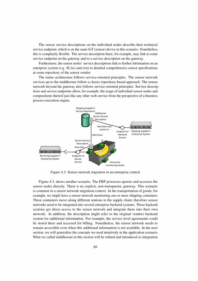
The sensor service descriptions on the individual nodes describe their technicalservice endpoint, which is on the same IoT (sensor) device in this scenario. Nonetheless,this is completely flexible. The service description there, for example, may link to someservice endpoint on the gateway and to a service description on the gateway.
Furthermore, the sensor nodes’ service descriptions link to further information on anenterprise system (e.g. SLAs) and even to detailed comprehensive sensor specificationsat some repository of the sensor vendor.
The entire architecture follows service-oriented principles. The sensor networkservices up to the middleware follow a classic repository-based approach. The sensornetwork beyond the gateway also follows service-oriented principles. Service descrip-tions and service endpoints allow, for example, the usage of individual sensor nodes andcompositions thereof just like any other web service from the perspective of a businessprocess execution engine.
Shipping Supplier’s
Enterprise System
Sensor Service
Description
Shipping Supplier’s
Service RepositoryAdditional
Sensor Service
Description
references
Endpoint of
Backend
Service
describes and
points to
Receiving Supplier’s
Enterprise System
Sensornet
monitoring Goods
Description
Endpoint of
Sensor
Service
describes
Figure 4.3: Sensor network migration in an enterprise context
Figure 4.3, shows another scenario. The ERP processes queries and accesses thesensor nodes directly. There is no explicit, non-transparent, gateway. This scenariois common in a sensor network migration context. In the transportation of goods, forexample, we might have a sensor network monitoring one or more shipping containers.These containers move along different stations in the supply chain; therefore sensornetworks need to be integrated into several enterprise backend systems. These backendsystems get direct access to the sensor network and integrate them into their ownnetwork. In addition, the description might refer to the original vendors backendsystem for additional information. For example, the service level agreements couldbe stored there and accessed for billing. Nonetheless, the sensor network needs toremain accessible even when this additional information is not available. In the nextsection, we will generalize the concepts we used intuitively in the application scenario.What we called middleware in this section will be refined and introduced as integration
89

platform. The integration platform is typically transparent, but could also be used tohost composed services.
4.7 Enterprise Integration Platform Architecture
In the following we present an architectural proposal based on the principles andideas discussed in Chapter 3 and Chapter 4. We provide an overview of how thoseconcepts can be used to enable the sensing enterprise. We present the architecture of aLinked Services enterprise platform and describe how we apply light-weight servicedescriptions to smart items and sensor networks. We are not going into too many detailson how Linked Service integration is carried out in regular enterprise networks andservice marketplaces, but present our extension to the concept. More information onLinked Service integration is given by Cardoso et al. [75, 77] and Razo-Zapata et al.[315].
En
terp
rise
La
ye
r
Se
rvic
e H
an
dli
ng
La
yer
PR
Ad
ap
ter
Se
rvic
e L
ife
cycl
eM
an
ag
em
en
t A
ge
nt
Se
rvic
e D
esc
rip
tio
n D
B
Resolve RDF
Agent
SD
Compression
unit
R
MoteRun
ner Agent
Physical
Resource
Agent
Physical Devices
R
Discovery Agent
Reconfiguration
Agent
Service
Description
Agent
Service Access
Agent
R
Lifecycle
Controller Agent
R
R
R
R
Service Mgm
Unit
On-device
Service Description
1
Service 1
Service n
2
Protocol boundaries
R
R
R
R
R
Netweaver Gateway
R ODATA
ERP
R
SAP RFC
Interface
Service Evaluation
(Linked USDL)
Needs to be standardized
Agent
Storage
R Communication channel. The arraw shows the direction of the Request „R“.
Modififing storage access
Smar
tIte
ms
/ S
enso
rs
Human Agent
Industry Risk
Analysis
Mo
bile
Dev
ices
Assistent App
R
Repository Registry
SD Access Agent
Netweaver Gateway
Enterprise Networks
R
R
R
Industry
ERP Reasoning
R
R
R
R
R
R
Industry
Context Engine
R
Context Agent
R
R
Figure 4.4: Architectural block diagram of the Linked Service enterprise platform.
Our platform, as shown in Fig. 4.4, enables an enterprise IT system to accessand evaluate Linked Services. We distinguish between two main building blocks: theenterprise layer and the integration platform. The integration platform (IP) consists ofthe service handling layer and the physical resource adapters (PR-adapters).
90

The enterprise layer can access both the integration platform and the smart itemsvia the service-oriented paradigm. As we consider IoT devices to be first-class entitiesin our service-oriented architecture, they are able to describe themselves through LinkedServices descriptions. The actual services are accessed via the service management unit.Interoperability is achieved via a standardization of the interface to the managementunit and of the service description language.
The ERP accesses the services provided by the IoT devices in the registry. Asthe service description is standardized it can evaluate its contents using the serviceevaluation component. The business information encoded in the service description isdomain-specific and it triggers further actions in the business processes running withinthe ERP. The actual means of access is described in the service endpoint description.In our system the endpoints are described in Linked USDL for IoT (see Chapter 5).Nonetheless, the architecture is not bound to Linked USDL. Any other solution can beused as well. Depending on the protocol used and the capabilities of the ERP systemeither a direct access is possible, the service-oriented integration platform could serveas a protocol gateway, or the integration platform itself could be the service endpoint[381].
The communication between the enterprise backend system and the integrationplatform is commonly carried out via a gateway component (e.g. SAP NetweaverGateway) that separates the ERP and auxiliary services. As the integration platformis just a service for the ERP system, communication takes place through a standardinterface known to the enterprise SOA environment. Nowadays, ERP systems stilluse a lot of heavy-weight proprietary protocols, e.g. BAPI or SAP RFC, whereas thecommunication with the SOA platform can be done via a standardized protocol. Theindustry is currently moving towards the Open Data Protocol (OData) as specified bythe OData consortium [274]. At an application layer, CoAP and HTTP seem to begood candidates in addition to Linked Services. This allows different ERP vendorsto implement their own integration platform without losing interoperability. Theseself-description capabilities allow the smart items to join an ERP backend system inorder to integrate into the system automatically based on the semantic informationfound in the service description, trigger backend actions and access the services on thesmart item.
The Integration Platform takes care of the actual handling of services on smartdevices. It is exposed to the enterprise layer through a service-oriented compatible inter-face. Thus, it gets integrated into an enterprise’ service-oriented environment. Withinthe Integration Platform there are several agents which we will describe briefly: Thediscovery agent (DA) interacts with the physical resource adapter (PRA) and discoversnew services available on new smart items. Communication with and monitoring ofsmart items is typically done via the physical resource adapter. New service descriptionsare first completed by the semantic resolution agent and (in case of compression) un-compressed by the service description compression unit. The service description agentis then responsible for adding the service to the ERPs service registry and repository,
91

thus making it available to the enterprise. Communication between the ERP and theservices on the mote either can be directly, for example for HTTP or CoAP-basedservices in an IPv6 network, or with the help of a service access gateway agent thatserves as gateway.
The deployment view of our envisioned semantic enterprise integration platform isshown in Figure 4.5 Several integration platforms called integration platform instances(IPI) can be used to talk to one or more wireless sensor networks. Specialized physicalresource adapters, for example for the Mote Runner system, are responsible for thecommunication between the sensor networks and a specific instance of the integrationplatform. The communication between the ERP and the individual device can be eitherdirect (transparent) or indirect. In an indirect scenario a service endpoint can be placedon the IPI via the specialized resource adapters. The only requirement we have towardsthe motes is that the IPI is notified when motes join or leave the WSN. Optionally, themotes can have a service description stored on them. This is necessary when third-partysmart objects join the domain of an enterprise. Information from the motes is then usedin the information and reasoning parts of the enterprise system, supported by ontologiesand domain knowledge.
Zone 1 Zone 2
IPI IPI IPI
IPI
IPI
WSN WSN WSN WSN
WSN WSN
WSN
WSN
ERP C&C SR DK
Enterprise
Data
Configuration / Monitoring
Write
Read/Write
Figure 4.5: Deployment view
The actual IPIs are deployed to different (geographical or logical) zones and controlone ore more motes. They are responsible for reading data from them or setting theirstate in case of an actuator.
Considering interoperability as it is currently done, one observes that almost alwaysa device-centric approach is used: Specific modules within the enterprise systeminteract with the sensing devices through proprietary protocols. Recently, the situationhas changed towards the more widespread use IP-based protocols and standardizedapplication level protocols.
We suggest moving away from the device-centric approach by leveraging on theSPBE conceptual framework as introduced in Chapter 4.5. The integration platform
92

W3C-SSN
ssn:observes
ssn:SensingDevice
ssn:observes
Semantic Entity
Repository
Sem
anti
c La
yer
Semantic Service
Repository
Domain specific
ontology
Inte
grat
ion
Lay
er
Bu
sin
ess
Laye
r
usdl
IPI
SPBEQL Engine
reads&controls (REST ful) (the physical sensors described by SSN).
Business expert
models
mo
del
s u
sin
g
Business Rules Business Rules
Component
Enterprise SOA platform
SPBE Services
invokes
creates
invokes
C&C
describes
PRA
Figure 4.6: SPBE in an enterprise modeling framework
needs support from the business layer/enterprise layer. Modeling tools allow to modelIoT-services on semantic repositories as shown in Figure 4.6. A semantic enterprisemodeling framework can be divided into three layers: a semantic layer, an integrationlayer and a business layer. The integration layer in Figure 4.6 refers to semanticintegration. The integration platform is only a part of it. As the image shows, the IPIcan be used to realize an SPBE integration layer. The components of the integrationplatform are abstracted as command&control (c&c) unit. All information that thebusiness expert needs to model an IoT system is stored in semantic repositories. Thebusiness expert uses a modeling tool that can access all the relevant information storedin semantic repositories. The semantic repositories can be further divided into domain-specific knowledge, semantic representations of physical entities and services relatedto those entities. A transition from legacy systems to such a framework is possible:Business objects are already stored in all kinds of data stores. The introduction ofidentifiers addressing these semantic repositories is necessary. Existing data can bemade available through service interfaces using semantic descriptions. This wouldnot introduce any changes to existing code. Access to all sorts of semantic entities isaccomplished through semantically described services as introduced in this work.
The business expert can formulate different rules that are expressed using SPBEs. Inour vision, the running business model is then to be executed by a (future) semantically-enriched business process execution engine. We call this execution engine SPBEQLengine. It can either access IoT-devices directly or it can create combined higher level
93
(integrated) services that run on the IPI. Those newly created services are added to thesemantic repositories and can be reused by business experts.
4.8 Conclusions
Semantics are omnipresent in nowadays enterprises. In future, leveraging on all thissemantic information will be crucial for enterprises. We identified the key drivers thatwill drive enterprises in the coming years. Namely: interoperability, use of standardizedtechnologies, enablement of sense-making and realtime business decision support.All those drivers, especially interoperability, sense making and real-time businesssupport would benefit from semantic service descriptions and Linked Services. Wesuggested an architecture that allows to integrate all kind of IoT-devices, based uponservice descriptions. We argue that a semantically- enriched platform and semantically-enriched Linked Services allow moving away from a device-centric view, to an entity orbusiness centric view. This not only eases the integration process and enables semanticinteroperability, it also allows easier modeling. To provide further support to a businessmodeler, or business domain specialist, we suggest an abstraction named semanticphysical business entity that can be used in enterprise architectures and especially inmodeling environments. It would enable the business modeler to navigate from entitiesto services easily. Semantic physical business entities can be used as part modelingBPMN modeling frameworks, for example, the approach of Meyer et al. [267, 265]that has been introduced in Chapter 1. Furthermore, a non-disruptive migration path iscritical, because one of the main challenges of innovation for an enterprise softwarevendor with a huge user base is to cope with the myriad of already existing code.Vendors prefer innovation that has a clear integration path into already existing systems,even for more disruptive technologies. Since most enterprise systems already useservice repositories as an integrated part of their SOA environment, the integration ofsemantic service descriptions would not change the paradigm of how software is writtentoday. Semantic services thus could be added to enterprise software in an incrementalmanner without the need of disruptive changes. As explained in Chapter 4.1 there isalready a lot of semantics in enterprise systems. The GDT in SAP systems can be seenas a kind of ontology. What is needed is to make the implicitly encoded knowledgemore explicit. This would not introduce significant changes to nowadays systems.Systems utilizing the business information and reasoning layer could provide additionalhigher level services based on SLAs, reasoning (e.g. ontology based virtual sensors) orthe connection of entities and (virtual) sensor data. This will allow new applications atan enterprise level by leveraging on the semantic repositories filled by the integrationplatform.
94

Part III
Implementation, ServiceDescriptions and Protocols
In the third part of this work we discuss two service descriptions: Linked USDL forIoT and the Open Data Protocol (OData). In Chapter 5 we discuss Linked USDL forIoT. We contribute four new vocabularies to Linked USDL. Each of these vocabulariestargets a specific aspect of the Internet of Things. The covered aspects are events, qualityof information, technical endpoints and the REST paradigm. Chapter 6 describes ourCoAP and OData implementation. We also discuss IoT-related modeling optionsfor OData and compare OData to traditional semantic web technologies, includingstrategies to merge the two worlds.
Furthermore, in Chapter 7, we discuss our Sleepy Nodes protocol and its imple-mentation. We present a scheduling framework to be used within IoT-systems and threedifferent scheduling strategies: A simple first fit, an exhaustive strategy and a strategybased on the observation that it is possible to combine measurements under certaincircumstances.

96

Chapter 5
Linked USDL for IoT
This chapter presents an IoT-extension [378, 259, 382, 187] for the Linked USDL [76]service description language. We contribute four new vocabularies to Linked USDL to
support Internet of Things applications. Each of these vocabularies targets a specificaspect of the Internet of Things. The covered aspects are events, quality of information,technical endpoints and the REST paradigm. We introduce each of these vocabulariesin detail. We call the set of vocabularies, in combination with the Linked USDL core ,as Linked USDL for IoT1. In the context of a semantics-aware enterprise architecture,as described in Chapter 4, Linked USDL for IoT is the service description that is storedon the mote and can be stored in one or more service description repositories. LinkedUSDL for IoT does not prescribe any technical protocol. It is a bottom-up approachwith respect to enterprise IoT integration.
5.1 Introduction
Linked USDL for IoT, similar to Linked USDL [76], follows the Linked Servicesphilosophy [297]. We already elaborated shortly the basic ideas of Linked Servicesin Chapter 4.4. In simple terms, Linked Services are based on two main principles:publishing (semantically-enhanced) service annotations and creating services that followLinked Data principles. Linked Data means essentially four things (based on Berners-Lee [50, 42]):
1. Use URIs as names for things [50]2. Use HTTP so that people can look up those names [50]3. When someone retrieves information by accessing an URI useful2 information
based on standards should be returned.4. Include links to other URIs, so that they can discover more things3 [50]
1available online: http://www.iot4bpm.de/usdl4iot.ttl2Berners-Lee does not specify what ”useful” means. This has to be seen in the context of the application.
The original formulation, which has been generalized here is: When someone looks up a URI, provideuseful information, using the standards (RDF, SPARQL) [50] [SIC]
3Things, in this context, means any information related to the original URI. It does not necessarily
97

We relax the original principles, without altering their meaning. We do not limitourselves to (semantic) web standards. For example, instead of HTTP, any RESTfulprotocol could be used to look up URIs.
Following the Linked Services idea (see also Chapter 4.4) of publishing (semantically-enhanced) service annotations, the service descriptions should describe their semanticand/or technical inputs and outputs, as well as their non-functional properties in termsof (reused or reusable) light-weight vocabularies. In the Internet of Things, as shownin the motivating example in Chapter 4.6.2, the possibility of linking to other URIs isalso particularly useful for partitioning service descriptions in a way that less spaceis consumed on the device, if needed. Only the parts of a service description that arereally needed are transmitted.
Linked USDL
usdl4iot
event usdl4iot-qoi
usdl4iot-rest
usdl4iot-ep
Lin
ked
USD
L fo
r Io
T
Figure 5.1: Linked USDL for IoT (building blocks)
Linked USDL for IoT, short LUSDL4IoT, is an implementation of the LinkedService idea consisting of the following building blocks (see also Figure 5.1):
Linked USDL Core The Linked USDL core is the base of all semantic modeling inLinked USDL for IoT. It covers the high-level concepts that are central to a ser-vice, such as basic service descriptions, service offerings descriptions, businessentities involvement, and service delivery communication by defining communi-cation channels and interaction points.
usdl4iot-event The event vocabulary can be used to model a publish-subscriber inter-face.
usdl4iot-qoi The qoi vocabulary is used to model Quality of Information (QoI) aspects.
mean Things as in Internet of Things.
98

usdl4iot-ep The ep (endpoint) vocabulary is used to describe the endpoint of a service.
usdl4iot-rest This vocabulary is used to describe the properties of an endpoint usingthe RESTful paradigm.
In the following we briefly discuss the application fields each of these vocabulariesare used for and also introduce briefly further Linked USDL extensions that could beused in conjunction with Linked USDL for IoT.
Traditionally, web service communication follows a request-response communica-tion scheme. This is sufficient for some applications, but many IoT applications needcommunication patterns that are more sophisticated. In this work we support threetypes of communication patterns:
Request/Response (R/S) The service consumer issues a request, which the serviceproviders answers either synchronously or asynchronously.
Publish/Subscribe (P/S) The publish/subscribe pattern allows a consumer to subscribeto particular events. As soon as this specific event occurs, the provider triggersa notification to the consumer. A subscriber-based communication model is anecessary precondition for running parts of business processes on smart objects,as these often need to react to specific events.
Time triggered While it can be argued that time-triggered is just a subclass of P/Sin IoT there are many sense and send applications. This specific pattern is socommon that it deserves to be a category of its own.
The R/S pattern is supported by Linked USDL. To support events we added asmall event vocabulary, called usdl4iot-event. Based on existing studies of event-basedsystems [174] we identified the following subset of typical P/S operations that wesupport in usdl-event: (i) register event subscriptions, (ii) remove event subscriptions,(iii) decouple resources from events and (iv) specify means of delivery, for example,callbacks.
Quality of Information is a subset of the more general concepts of Quality of Serviceand uncertainty of information. In the Internet of Things domain Quality of Informationis of special interest when dealing with sensors and actuators. We have only imperfectsensing technologies, and insufficient and/or incomplete contextual knowledge. Thismeans that sensors and actuators inherently have the problem that the informationprovided or the action performed might not be correct, imprecise or depend on somestatistical model. Therefore the uncertainty of the data a service can provide has to besufficiently described.
In the Internet of Things domain a common approach is to look at two specificQuality of Information aspects: Quality of Sensing and Quality of Actuation. Wemodeled the vocabulary based on previous work on quality of information parameters,as shown in Table 5.1
99

Property Description
PrecisionSheikh et al.[348],Buchholz et al.[64]
How exactly the provided context information mir-rors the reality[64], Granularity with which contextinformation describes a real world situation [348]Typical metrics: Depends on subject, e.g. positionprecision of a localization in cm
FreshnessSheikh et al.[348], Buchholz etal.[64]
Time that elapses between the determination of con-text information and its delivery to a requester [348]
Typical metrics: Time span / Age of data, in seconds
Uncertainty of Informa-tion, Probability of cor-rectness, Trust worthi-ness, Confidence, Cer-taintySheikh et al. [348], Buchholz etal.[64], Laskey et al.[228], Guet al.[146], Loke[239]
Probability that a piece of context information iscorrect [64], How likely is that the provided informa-tion is correct. [64] Probability that an instance ofcontext accurately represents the corresponding realworld situation, as assessed by the context source, atthe time it was determined [348]
Typical metrics: percentage values, levels, probabil-ity function
Table 5.1: Quality of Information: Overview of Concepts
The four Linked Data principles map very well to the RESTful paradigm [50],which is currently predominant in the web and has great chances of dominating theInternet of Things as well [149]. Linked USDL for IoT was therefore designed with theprimary goal of supporting the RESTful paradigm.
The Linked USDL core vocabulary can be extended by the following furtherdomain-specific ontologies [76]. They can be used to extend Linked USDL for IoT.
usdl-price usdl-price can be used to describe price structures in the service industry.According to the maturity classification as described in [76] it is regarded asready to use and validated.
usdl-agreement usdl-agreement [135] covers functional and non-functional quality ofservice. It is classified as having past the proof-of-concept phase and is now invalidation [76].
usdl-sec This module covers security aspects of a service. Service providers can use itto describe security related features of their services. It is classified as being inthe proof-of-concept phase [76].
100

usdl-ipr This USDL module covers legal aspects of accessing a service, such as accessrights and copyrights. It is classified as being in the proof-of-concept phase [76].
5.2 Design Principles
The Linked USDL vocabulary for IoT (USDL4IoT) follows the same lightweight ideasas Linked USDL does. Our vocabulary is developed in an iterative use-case drivenapproach [283]. The goal of Linked USDL for IoT is to allow publishing and retrievingof IoT-Services in heterogeneous environments and to standardize the common core, i.e.the properties all these services have in common. We aim to capture the most importantconcepts only. Domain-specific details are delegated to additional ontologies, followingone of the core ideas of Linked Services. We specified the communication patterns upto a degree that allows to model typical IoT-service interactions. Nonetheless, it wouldbe possible to extend it to also support full-blown web-services and more complicatedinteraction schemes.
Considering the original design decisions of Linked USDL [296], and aiming for abecoming a regular member of the Linked USDL family of vocabularies, we identifiedfour principles that guided the design of Linked USDL for IoT: lightweight, coherency,extensibility and compatibility. We choose them in order to ensure a seamless integrationof Linked USDL for IoT into the Linked USDL core vocabulary and the already existingextensions. In the following we will briefly describe the four principles and their mainproperties:
1. Lightweight: We wanted to cover the most important aspects only, avoidingthe possibility of over-specifying and, therefore, limiting the applicability of thevocabularies. In particular, domain-specific knowledge needs to be specified by(external) ontologies. This is inline with the original design methodology ofLinked USDL that was centered on the reuse of widely adopted vocabularies[296].
2. Coherency: Our extension needs to integrate well into Linked USDL. Conceptsand modeling style should follow the one used in Linked USDL to ensure that itseamlessly integrates into the existing Linked USDL vocabulary.In our opinionintroducing a modeling-style that differ from what is used in the core ontologywould lower the acceptance of the IoT extension.
3. Extensibility: The vocabulary is designed with evolution and extensibility inmind. It needs to integrate well with existing well-known external ontologies.The concepts need to be generic enough to provide extension points for domain-specific vocabularies.
4. Compatibility: We aim for compatibility with existing (high-level) concepts andfor easy integration into existing systems.
101
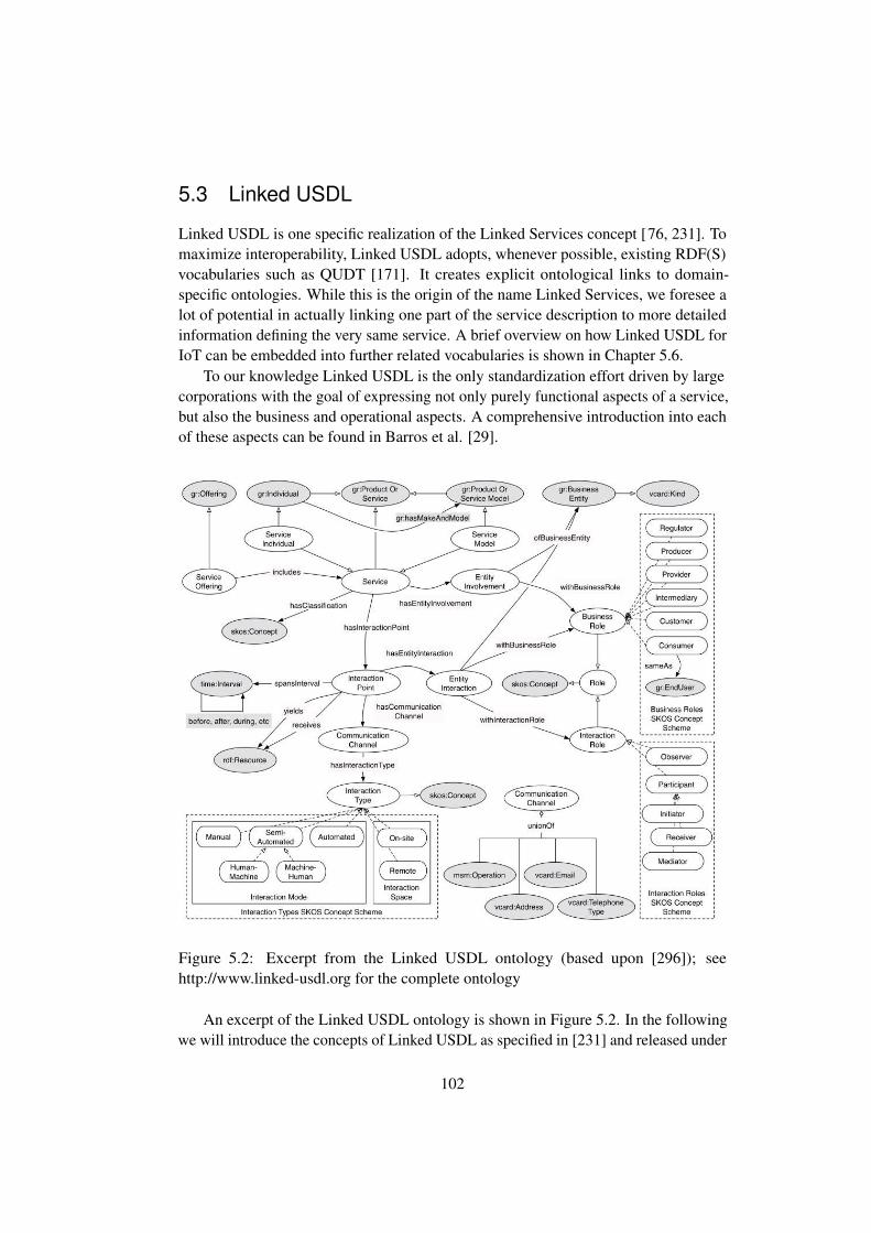
5.3 Linked USDL
Linked USDL is one specific realization of the Linked Services concept [76, 231]. Tomaximize interoperability, Linked USDL adopts, whenever possible, existing RDF(S)vocabularies such as QUDT [171]. It creates explicit ontological links to domain-specific ontologies. While this is the origin of the name Linked Services, we foresee alot of potential in actually linking one part of the service description to more detailedinformation defining the very same service. A brief overview on how Linked USDL forIoT can be embedded into further related vocabularies is shown in Chapter 5.6.
To our knowledge Linked USDL is the only standardization effort driven by largecorporations with the goal of expressing not only purely functional aspects of a service,but also the business and operational aspects. A comprehensive introduction into eachof these aspects can be found in Barros et al. [29].
Figure 5.2: Excerpt from the Linked USDL ontology (based upon [296]); seehttp://www.linked-usdl.org for the complete ontology
An excerpt of the Linked USDL ontology is shown in Figure 5.2. In the followingwe will introduce the concepts of Linked USDL as specified in [231] and released under
102

a Creative Commons license.
usdl:Service
A usdl-service describes a service. It is the initial entry point for service consumers. Thedescription contains functional properties of the service, described by the interactionprotocol as well as non-functional properties described by qualitative or quantitativevalues [231].
Listing 5.1: Linked USDL service definition
usdl:Service a rdfs:Class, owl:Class;rdfs:isDefinedBy <http://linked-usdl.org/ns/usdl>;rdfs:label "Service"@en ;rdfs:subClassOf gr:ProductOrService .
Linked USDL for IoT bases all of its service descriptions on usdl:service. EveryLinked USDL for IoT service is, therefore, also a Linked USDL service.
usdl:ServiceOffering
A ServiceOffering is an offering made by a gr:BusinessEntity to its customers. Anoffering is part of the business side of Linked USDL. It usually includes a price, legalterms, and service level agreements.
Listing 5.2: Linked USDL Service offering
usdl:ServiceOffering a rdfs:Class, owl:Class;rdfs:isDefinedBy <http://linked-usdl.org/ns/usdl>;rdfs:label "Service Offering"@en ;rdfs:subClassOf gr:Offering .
An actual service is added to a particular ServiceOffering using the include property.usdl:ServiceOffering allows specifying bundles of services traded as one entity. It isnot meant for creating composite services. All Linked USDL for IoT service offeringsare modeled with usdl:ServiceOffering.
Listing 5.3: Linked USDL relationship between service and service offering
usdl:includes a rdf:Property;rdfs:isDefinedBy <http://linked-usdl.org/ns/usdl>;rdfs:label "includes"@en ;rdfs:subPropertyOf gr:includes;rdfs:domain usdl:ServiceOffering;rdfs:range usdl:Service .
103
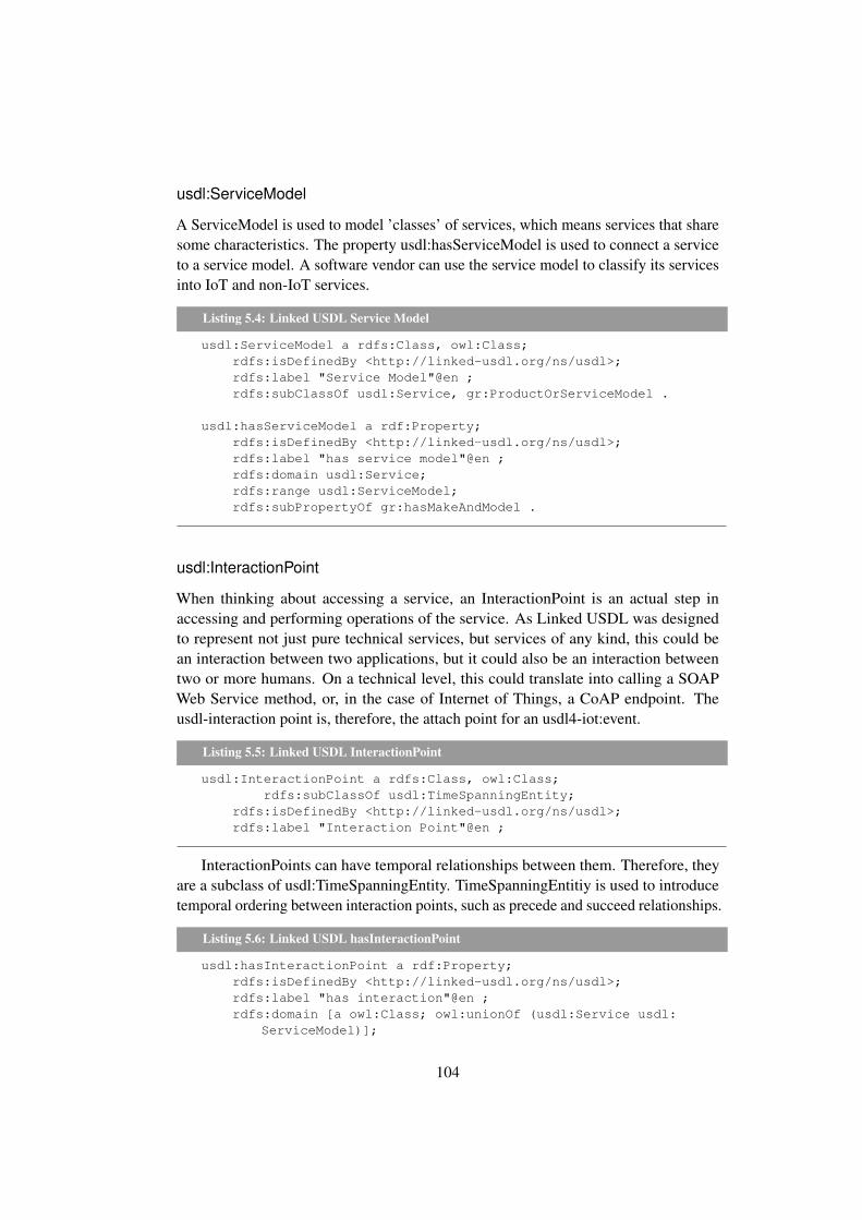
usdl:ServiceModel
A ServiceModel is used to model ’classes’ of services, which means services that sharesome characteristics. The property usdl:hasServiceModel is used to connect a serviceto a service model. A software vendor can use the service model to classify its servicesinto IoT and non-IoT services.
Listing 5.4: Linked USDL Service Model
usdl:ServiceModel a rdfs:Class, owl:Class;rdfs:isDefinedBy <http://linked-usdl.org/ns/usdl>;rdfs:label "Service Model"@en ;rdfs:subClassOf usdl:Service, gr:ProductOrServiceModel .
usdl:hasServiceModel a rdf:Property;rdfs:isDefinedBy <http://linked-usdl.org/ns/usdl>;rdfs:label "has service model"@en ;rdfs:domain usdl:Service;rdfs:range usdl:ServiceModel;rdfs:subPropertyOf gr:hasMakeAndModel .
usdl:InteractionPoint
When thinking about accessing a service, an InteractionPoint is an actual step inaccessing and performing operations of the service. As Linked USDL was designedto represent not just pure technical services, but services of any kind, this could bean interaction between two applications, but it could also be an interaction betweentwo or more humans. On a technical level, this could translate into calling a SOAPWeb Service method, or, in the case of Internet of Things, a CoAP endpoint. Theusdl-interaction point is, therefore, the attach point for an usdl4-iot:event.
Listing 5.5: Linked USDL InteractionPoint
usdl:InteractionPoint a rdfs:Class, owl:Class;rdfs:subClassOf usdl:TimeSpanningEntity;
rdfs:isDefinedBy <http://linked-usdl.org/ns/usdl>;rdfs:label "Interaction Point"@en ;
InteractionPoints can have temporal relationships between them. Therefore, theyare a subclass of usdl:TimeSpanningEntity. TimeSpanningEntitiy is used to introducetemporal ordering between interaction points, such as precede and succeed relationships.
Listing 5.6: Linked USDL hasInteractionPoint
usdl:hasInteractionPoint a rdf:Property;rdfs:isDefinedBy <http://linked-usdl.org/ns/usdl>;rdfs:label "has interaction"@en ;rdfs:domain [a owl:Class; owl:unionOf (usdl:Service usdl:
ServiceModel)];
104

rdfs:range usdl:InteractionPoint .
The semantical link to the input and output of an interaction point is modeled withthe properties usdl:receives and usdl:yields. The range of both of them is rdfs:class, soit is possible to establish a link to an arbitrary domain specific ontology.
Listing 5.7: Linked USDL receives and yields definition
usdl:receives a rdf:Property;rdfs:isDefinedBy <http://linked-usdl.org/ns/usdl>;rdfs:label "receives"@en ;rdfs:domain usdl:InteractionPoint;rdfs:range rdfs:Class.
usdl:yields a rdf:Property;rdfs:isDefinedBy <http://linked-usdl.org/ns/usdl>;rdfs:label "yields"@en ;rdfs:domain usdl:InteractionPoint;rdfs:range rdfs:Class.
The communication taking part at an interaction point is modeled as Communi-cationChannel. The term was chosen to be rather generic because Linked USDL wasdesigned to support all kinds of communication. Linked USDL itself does not define anyspecific CommunicationChannels. In case of human contacts, it could refer to vCard(e.g. email, phone). Operations in Linked USDL for IoT are modeled as communicationchannels.
5.4 IoT-specific Vocabularies
In the following, we discuss the actual implementation of Linked USDL for the IoT(in short, LinkedUSDL4IoT). We generally distinguish between a semantical and atechnical part. The semantical part is mainly used to model the semantic relations,whereas the technical part is mainly used to model the specific parts of a technicalendpoint.
5.4.1 Vocabulary: Endpoint and Application-layer Support
We model the supported application-layer protocol as ApplicationProtocol class. Proto-col layers below the application layer are out of scope, but they could be modeled in anorthogonal way, if needed.
Listing 5.8: Linked USDL for IoT: Application Protocol class
usdl4iot-ep:ApplicationProtocol a rdfs:Class, owl:Class;rdfs:isDefinedBy <http://research.sap.com/IoT/usdl4iot-ep>;rdfs:label "Application Protocol"@en ;rdfs:comment "Technical high-level application protocol"@en .
105

We support the two most common REST-based application layer protocols, namelyHTTP and CoAP. Our main focus in this thesis was CoAP, hence all the experimentswere conducted based on a CoAP application layer. HTTP could be an option forsystems based on less constrained devices. As a third option, we foresee the use ofcustom (REST-like) protocols. We define a separate application protocol endpoint forthat case (APCustom). Custom protocols are a subclass of APCustom.
Listing 5.9: Linked USDL for IoT: Application layer protocol definitions
usdl4iot-ep:APCoAP a rdfs:Class, owl:Class;rdfs:isDefinedBy <http://research.sap.com/IoT/usdl4iot-ep>;rdfs:label "CoAP Application Protocol"@en ;rdfs:comment "CoAP Application Protocol"@en ;
rdfs:subClassOf usdl4iot-ep:ApplicationProtocol .
usdl4iot-ep:APHttp a rdfs:Class, owl:Class;rdfs:isDefinedBy <http://research.sap.com/IoT/usdl4iot-ep>;rdfs:label "HTTP Application Protocol"@en ;rdfs:comment "HTTP Application Protocol"@en ;
rdfs:subClassOf usdl4iot-ep:ApplicationProtocol .
usdl4iot-ep:APCustom a rdfs:Class, owl:Class;rdfs:isDefinedBy <http://research.sap.com/IoT/usdl4iot-ep>;rdfs:label "Custom Application Protocol"@en ;rdfs:comment "Custom Application Protocol"@en ;
rdfs:subClassOf usdl4iot-ep:ApplicationProtocol .
Independent of the underlying application-layer protocol, we will follow the notionsof operations and parameters. The abstraction chosen for modeling services can beused for any underlying application-layer protocol that can be mapped to operationswith accompanying input and output parameters.
Listing 5.10: Linked USDL for IoT: Application layer protocol definition - Operation
usdl4iot-ep:Operation a rdfs:Class, owl:Class;rdfs:isDefinedBy <http://research.sap.com/IoT/usdl4iot-ep>;rdfs:label "Operation"@en ;rdfs:comment "An operation offered by the service, yielding an
output for a given input"@en ;isSubclassOf usdl:CommunicationChannel.
usdl4iot-ep:Parameter a rdfs:Class, owl:Class;rdfs:isDefinedBy <http://research.sap.com/IoT/usdl4iot-ep>;rdfs:label "Parameter"@en ;rdfs:comment "A parameter conceptually describes the input or
output of an operation"@en .
Based on that abstraction, we define the properties that define an operation – namelyhasInput, hasOutput, hasType, isOptional, representAn and hasValueLink. The first twofurther define an operation and its parameter. hasInput connects an operation with a
106

parameter and marks it as an input parameter; hasOutput works similarly for outputparameters. A datatype is attached to a parameter by using hasType. Furthermore, aparameter can be marked as optional.
The remaining two properties representAn and hasValueLink are used for semanticallinking. representAn links to the semantic concept a parameter represents. For example,a temperature parameter could have a datatype of xsd:float. All that is known up tothis point is that there is a parameter and that it expects or return a float value. Tointerpret this value at higher level, the representsAn semantical link can be used to,for example, link this parameter to a temperature ontology and more specifically tothe entity TemperatureCelcius. Now, from a semantic point of view, it is obvious thatthe parameter represents a temperature in degree Celcius and that it is (technically)encoded as a float value.
Listing 5.11: Linked USDL for IoT: Application layer protocol definitions
usdl4iot-ep:hasInput a rdf:Property ;rdfs:isDefinedBy <http://research.sap.com/IoT/usdl4iot-ep>;rdfs:domain usdl4iot-ep:Operation ;rdfs:range usdl4iot-ep:Parameter .
usdl4iot-ep:hasOutput a rdf:Property ;rdfs:isDefinedBy <http://research.sap.com/IoT/usdl4iot-ep>;rdfs:domain usdl4iot-ep:Operation ;rdfs:range usdl4iot-ep:Parameter .
usdl4iot-ep:representsAn a rdf:Property;rdfs:isDefinedBy <http://research.sap.com/IoT/usdl4iot-ep>;rdfs:comment "Connects a parameter to the high level concept
it represents"@en ;rdfs:domain usdl4iot-ep:Parameter ;rdfs:range rdfs:Class .
usdl4iot-ep:hasType a rdf:Property;rdfs:isDefinedBy <http://research.sap.com/IoT/usdl4iot-ep>;rdfs:comment "The parameter value’s type, e.g. xsd:int for
integers"@en ;rdfs:domain usdl4iot-ep:Parameter ;rdfs:range rdfs:resource .
usdl4iot-ep:isOptional a rdf:Property ;rdfs:domain usdl4iot-ep:Parameter ;dfs:comment "Specifies whether parameter is required for the
operation"@en ;rdfs:range xsd:boolean .
usdl4iot-ep:hasValueLink a rdf:Property ;rdfs:isDefinedBy <http://research.sap.com/IoT/usdl4iot-ep>;rdfs:comment "Specifies the parameter’s concrete value in the
output document"@en ;rdfs:domain usdl4iot-ep:Parameter ;
107

rdfs:range rdf:Literal .
5.4.2 Vocabulary: Event Support
The usdl4iot-event vocabulary is used to describe events and a generic publish/subscribecommunication pattern. We decided not to support any further refinement of events, asthis is to be defined by the application scenario. For example, an event could be raisedif the temperature of a given good is above a given threshold. The vocabulary thereforecan get by with two classes: An Event and a Publisher.
Listing 5.12: Publiser/Event interface in Linked USDL4IoT
usdl4iot-event:Event a rdfs:Class, owl:Class;rdfs:isDefinedBy <http://research.sap.com/IoT/usdl4iot-event>;rdfs:label "Event"@en ;rdfs:comment "Any kind of event occuring within the scope of
the service"@en .
usdl4iot-event:Publisher a rdfs:Class, owl:Class;rdfs:isDefinedBy <http://research.sap.com/IoT/usdl4iot-event>;rdfs:label "Publisher"@en ;rdfs:comment "Actor which autonomously generates events"@en .
On a semantic level, we attach the publisher to the interaction point of the usdl-coreontology. Each publisher can support an infinite number of events via the hasEventproperty.
Listing 5.13: Publiser/Event interface in Linked USDL4IoT
usdl4iot-event:hasPublisher a rdf:Property;rdfs:isDefinedBy <http://research.sap.com/IoT/usdl4iot-event>;rdfs:domain usdl-core:InteractionPoint;rdfs:range usdl4iot-event:Publisher.
usdl4iot-event:hasEvent a rdf:Property;rdfs:isDefinedBy <http://research.sap.com/IoT/usdl4iot-event>;rdfs:domain usdl4iot-event:Publisher;rdfs:range usdl4iot-event:Event.
On an operational level, we need to connect the events generated and the subscribeand unsubscribe operations to endpoint operations. Each event is connected to a sub-scribe (hasSubscribeOperation) or unsubscribe operation (hasUnsubscribeOperation)and can generate one or more output parameters (generates).
Listing 5.14: REST verbs in Linked USDL4IoT
usdl4iot-event:hasSubscribeOperation a rdf:Property ;rdfs:isDefinedBy <http://research.sap.com/IoT/usdl4iot-event>;rdfs:domain usdl4iot-event:Event ;
108
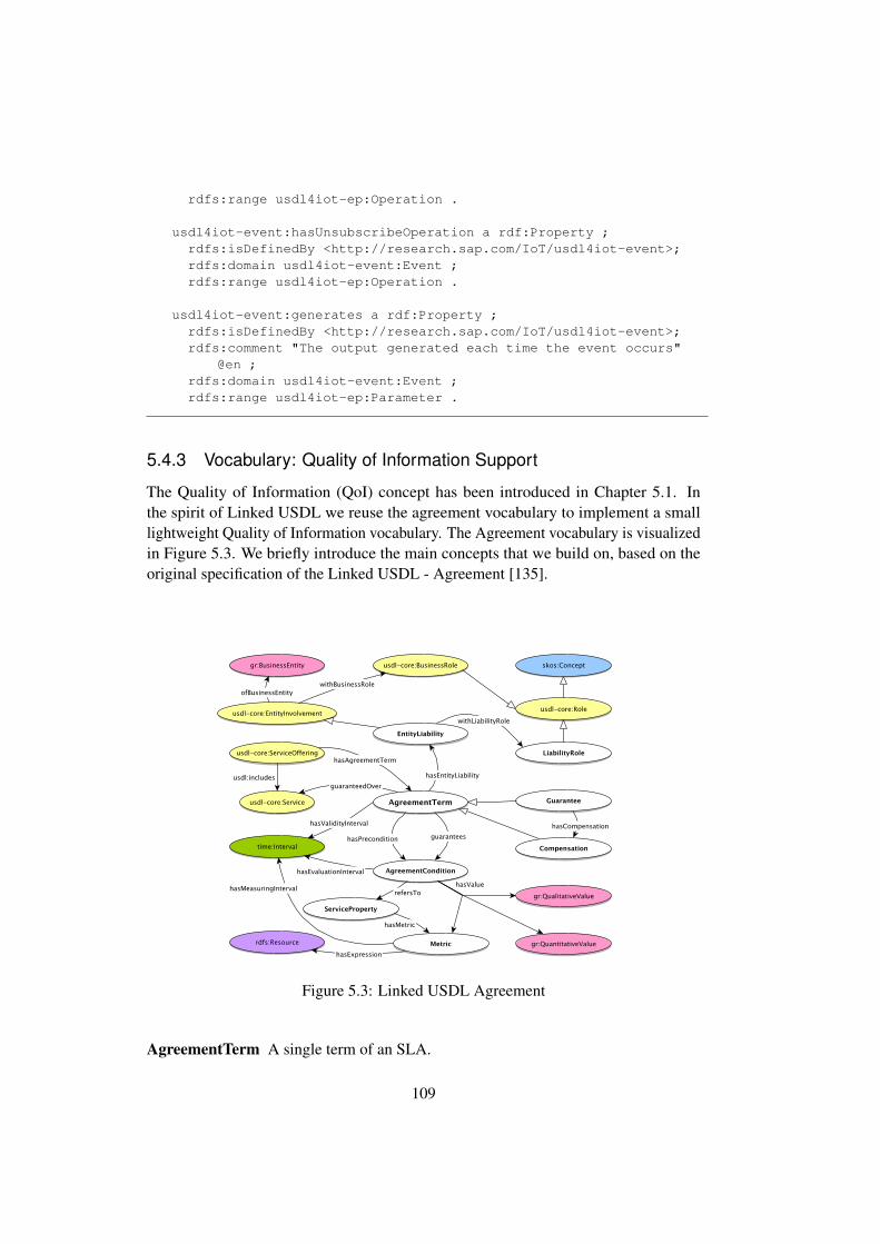
rdfs:range usdl4iot-ep:Operation .
usdl4iot-event:hasUnsubscribeOperation a rdf:Property ;rdfs:isDefinedBy <http://research.sap.com/IoT/usdl4iot-event>;rdfs:domain usdl4iot-event:Event ;rdfs:range usdl4iot-ep:Operation .
usdl4iot-event:generates a rdf:Property ;rdfs:isDefinedBy <http://research.sap.com/IoT/usdl4iot-event>;rdfs:comment "The output generated each time the event occurs"
@en ;rdfs:domain usdl4iot-event:Event ;rdfs:range usdl4iot-ep:Parameter .
5.4.3 Vocabulary: Quality of Information Support
The Quality of Information (QoI) concept has been introduced in Chapter 5.1. Inthe spirit of Linked USDL we reuse the agreement vocabulary to implement a smalllightweight Quality of Information vocabulary. The Agreement vocabulary is visualizedin Figure 5.3. We briefly introduce the main concepts that we build on, based on theoriginal specification of the Linked USDL - Agreement [135].
Figure 5.3: Linked USDL Agreement
AgreementTerm A single term of an SLA.
109
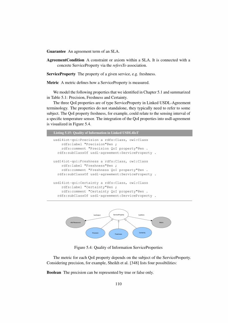
Guarantee An agreement term of an SLA.
AgreementCondition A constraint or axiom within a SLA. It is connected with aconcrete ServiceProperty via the refersTo association.
ServiceProperty The property of a given service, e.g. freshness.
Metric A metric defines how a ServiceProperty is measured.
We model the following properties that we identified in Chapter 5.1 and summarizedin Table 5.1: Precision, Freshness and Certainty.
The three QoI properties are of type ServiceProperty in Linked USDL-Agreementterminology. The properties do not standalone, they typically need to refer to somesubject. The QoI property freshness, for example, could relate to the sensing interval ofa specific temperature sensor. The integration of the QoI properties into usdl-agreementis visualized in Figure 5.4.
Listing 5.15: Quality of Information in Linked USDL4IoT
usdl4iot-qoi:Precision a rdfs:Class, owl:Classrdfs:label "Precision"@en ;rdfs:comment "Precision QoI property"@en .
rdfs:subClassOf usdl-agreement:ServiceProperty .
usdl4iot-qoi:Freshness a rdfs:Class, owl:Classrdfs:label "Freshness"@en ;rdfs:comment "Freshness QoI property"@en .
rdfs:subClassOf usdl-agreement:ServiceProperty .
usdl4iot-qoi:Certainty a rdfs:Class, owl:Classrdfs:label "Certainty"@en ;rdfs:comment "Certainty QoI property"@en .
rdfs:subClassOf usdl-agreement:ServiceProperty .
Figure 5.4: Quality of Information ServiceProperties
The metric for each QoI property depends on the subject of the ServiceProperty.Considering precision, for example, Sheikh et al. [348] lists four possibilities:
Boolean The precision can be represented by true or false only.
110

Numeric Information that can be represented by numerical values, for example theprecision of a temperature reading.
Incremental Sets A series of sets, which progressively represent higher informationvalue.
Weighted Sets Sets of discrete values that cannot be arranged in a series of increasingprecision. An assigned weight shows the information value of each set.
Given the wide range of possible subjects and their metrics, we follow the LinkedUSDL principle of delegating them to specialized ontologies. From a SLA point ofview, for Internet of Things services, standardization in terms of what the possibleQoI properties are is more important than specify each and every detail of its metric.Based upon our initial usdl-qoi more quality of information ServiceProperties could bespecified, if needed.
5.4.4 Vocabulary: REST Support
The usdl4iot-rest vocabulary further refines the endpoint specification by mapping it tothe RESTful paradigm.
We support REST-based systems using the well-known methods/verbs GET, PUT,POST, DELETE, HEAD, TRACE, and CONNECT. These verbs are supported byHTTP. CoAP supports only the subset GET, PUT, POST and DELETE.
Listing 5.16: REST verbs in Linked USDL4IoT
usdl4iot-rest:Method a rdfs:Class, owl:Classrdfs:label "Method"@en ;rdfs:comment "A RESTful verb"@en .
usdl4iot-rest:POST a rdfs:Class, owl:Class ;rdfs:label "POST"@en ;rdfs:comment "POST"@en ;
rdfs:subClassOf usdl4iot-rest:Method .
usdl4iot-rest:PUT a rdfs:Class, owl:Class ;rdfs:label "PUT"@en ;rdfs:comment "PUT"@en ;
rdfs:subClassOf usdl4iot-rest:Method .
usdl4iot-rest:GET a rdfs:Class, owl:Class ;rdfs:label "GET"@en ;rdfs:comment "GET"@en ;
rdfs:subClassOf usdl4iot-rest:Method .
usdl4iot-rest:DELETE a rdfs:Class, owl:Class ;rdfs:label "DELETE"@en ;rdfs:comment "DELETE"@en ;
rdfs:subClassOf usdl4iot-rest:Method .
111

usdl4iot-rest:HEAD a rdfs:Class, owl:Class ;rdfs:label "HEAD"@en ;rdfs:comment "HEAD"@en ;
rdfs:subClassOf usdl4iot-rest:Method .
usdl4iot-rest:TRACE a rdfs:Class, owl:Class ;rdfs:label "TRACE"@en ;rdfs:comment "TRACE"@en ;
rdfs:subClassOf usdl4iot-rest:Method .
usdl4iot-rest:CONNECT a rdfs:Class, owl:Class ;rdfs:label "CONNECT"@en ;rdfs:comment "CONNECT"@en ;
rdfs:subClassOf usdl4iot-rest:Method .
The uniform interface, as introduced in Chapter 2.4, is defined by URI templates.URI templates (and similar concepts) have been defined early on as part of severalspecifications, including WSDL [88] and WADL [154]. Subsequently, it has beenstandardized. We support a simplified subset of URI templates as defined in RFC6570[144]. URI templates are used for describing Uniform Resource Identifiers throughvariable expansion. They provide an easy mechanism for abstracting resource identifiersin such a way that the variable parts can be easily identified and described. RFC6570defines URI templates as follows:
URI Templates are similar to a macro language with a fixed set ofmacro definitions: the expression type determines the expansion process.The default expression type is simple string expansion, wherein a singlenamed variable is replaced by its value as a string after pct-encoding anycharacters not in the set of unreserved URI character. [144]
In usdl4iot-rest, we define two main classes as entry points for describing theuniform interface: URITemplate and URIBinding. The URITemplate represents apattern to model an URI containing placeholders to be replaced by input parameters.The URIBinding binds a certain placeholder in a URI template to the parameter whosevalue should replace it.
Listing 5.17: URI templates
usdl4iot-rest:URITemplate a rdfs:Class, owl:Class;rdfs:isDefinedBy <http://research.sap.com/IoT/usdl4iot-ep>;rdfs:label "URI Template"@en ;rdfs:comment "A pattern to model an URI containing
placeholders to be replaced by input parameters"@en.
usdl4iot-rest:URIBinding a rdfs:Class, owl:Class;rdfs:isDefinedBy <http://research.sap.com/IoT/usdl4iot-ep>;rdfs:label "URI Binding"@en ;
112

rdfs:comment "Binds a certain placeholder in a URI template tothe parameter whose value should replace it"@en.
usdl4iot-rest:hasPlaceholderName a rdf:Property;rdfs:isDefinedBy <http://research.sap.com/IoT/usdl4iot-rest>;rdfs:comment "Name of the placeholder to be replaced in the
template, without the curly brackets’"@en;rdfs:domain usdl4iot-rest:URIBinding ;rdfs:range rdf:Literal .
usdl4iot-rest:hasPlaceholderParameter a rdf:Property;rdfs:isDefinedBy <http://research.sap.com/IoT/usdl4iot-rest>;rdfs:comment "Defines the parameter whose value should be used
for the replacement"@en;rdfs:domain usdl4iot-rest:URIBinding ;rdfs:range usdl4iot-ep:Parameter .
The usdl4iot-rest:hasPlaceholderName property binds a placeholder name to aliteral and hasPlaceholderParameter is used to define the parameter whose valueshould be used as a replacement for the placeholder (called string expansion [144] inRFC6750 terminology). Therefore, it makes the implicitly available information aboutplaceholders within the URI template explicit. For each of these bindings, (semantic)information about the meaning of the parameter is added.
5.5 Representations
The representation of resources for REST-based and non REST-based systems with andwithout semantics has been a research topic that received a lot of attention during thelast years. Linked USDL4IoT, as a service description language, does not prescribe anyspecific data representation. Nonetheless, at the time of writing, JSON and its semanticcounterpart JSON-LD seems to be the upcoming de-facto standards. JSON is currentlyused in many new RESTful enterprise developments. Moreover, the need for JSON(JavaScript Object Notation) [60, 114] to be extended to support semantics as wellhas been identified by the W3C. In 2014 it released a W3C Recommendation calledJSON-LD [226].
Linked USDL for IoT can easily be integrated into JSON/JSON-LD, XML-basedformats such as WSDL, as well as part of a pure textual description.
JSON-LD was designed so that developers would not need to know about any othersemantic web technology [226]. It is, quite close to regular JSON. It is syntacticallyfully compatible with JSON; hence, all tools and preexisting toolchains can be reused.In the same way as our architecture provided a smooth path towards semantics, JSON-LD aims for a smooth integration into already existing tools. One of the design goalsof JSON-LD was to lower the entry barriers for enterprise developers. JSON-LD, likeLinked USDL for IoT, is not a complete technology stack. According to the authors(JSON-LD) needs ontologies to express domain semantics [226]. LinkedUSDL4IoT
113

and JSON-LD complement each other, and combined with the IoT-stack and domain-specific ontology form a complete technology stack.
JSON/JSON-LD and Linked USDL for IoT can be integrated in two differentways: First, in the case of only JSON (without -LD) a semantical link from eachreturned data to the semantics can be established by using the unique ValueLink, whichcan be attached to parameters. The processing system now make the link from thedata representation to the service description. This approach can also be followed forJSON-LD. Furthermore, JSON-LD can be used independently by referring to the sameontologies as Linked USDL for IoT, thus giving the same references to the same entitiesin its response.
To connect WSDL/SOAP with Linked USDL, we leverage on ideas from WSDL-S[6]. WSDL-S based references (modelReference) from a WSDL description to a highlevel ontology is currently used by most semantic approaches, including the OWL-S[249, 251, 250] and WSMO [122, 322] approaches. OWL-S and WSMO are introducedin Chapter 2.11.2 and Chapter 2.11.3.
WSDL-S Schema definition excerpt based on [6]
<?xml version="1.0" encoding="UTF-8"?><schema xmlns="http://www.w3.org/2001/XMLSchema"targetNamespace="http://lsdis.cs.uga.edu/projects/meteor-s/wsdl-s
/examples/purchaseOrder.wsdl"xmlns:wssem="http://lsdis.cs.uga.edu/projects/meteor-s/wsdl-s/
examples/purchaseOrder.wsdl"xmlns:wsdl="http://schemas.xmlsoap.org/wsdl/">
<attribute name="modelReference" type="anyURI" use="optional"/>[...]</schema>
Notably, we use WSDL-S and its wssem:modelReference to connect operationsand parameters with Linked USDL for IoT endpoints, and encode the same semanticinformation there. Furthermore, parameters can be mapped to their respective LinkedUSDL for IoT description by using the ValueLink again. In that case, the link betweenan endpoint and higher level semantics is solely done through usdel4iot-ep:representsAnand, on a service level, the usdl:yields and usdl:receives properties.
To sum up, we now have a vocabulary for specifying the actual means of accessingan IoT-service by specifying the application layer protocol, operations the service canperform, as well as the data encoding. Moreover, links to domain-specific ontologiescan be specified. We would like to emphasize here that this description is meant tobe used for constrained devices. More complex services that demand features goingbeyond the current capabilities of our vocabulary, are not in the scope of Linked USDLfor IoT. The structure of the vocabulary is designed to be extensible though. We expect itto evolve over time and incorporate many more features known from today’s enterprisearchitectures.
114

5.6 Relationship to further Ontologies
Linking vocabularies instead of a one-fits-it-all approach is one of the main design goalsof Linked USDL. In this section we briefly introduce some ontologies that could beused with Linked USDL for IoT to form a larger service ecosystem. Linked USDL4IoTcan be embedded into a more comprehensive framework, in conjunction with otherontologies, to describe the Internet of Things domain fully. Of course, domain specificaspects of an IoT-application are not covered by these and external ontologies are stillneeded.
Linked USDL
usdl4iot-
event
usdl4iot-rest
usdl4iot-ep
SSN
Usdl4iot-qoi
QUQD
QoI
WSN
Datatypes
Domain Specific Ontologies
Application
IOT-A Domain Model
IOT
-A D
om
ain
Model
Services
Figure 5.5: Relationship to Further Ontologies
The most prominent ontology in the sensor network field, and one of the few thathas reached consensus among many researches, is most likely the Semantic SensorNetwork (SSN) ontology4. The SSN ontology provides a rather high-level vocabularyto describe sensor network landscapes, that is, sensor nodes and sensor observation andmeasurement data. It does not provide any service support, generic IoT-enablement norany support for units or quantities of sensor measurements. The service part is coveredby Linked USDL and Its IoT extensions. Considering the Internet of Things one canleverage on the IoT-A domain model[33] and its concepts. It introduces the concept ofPhysical Entities to describe real-world things, devices and resources connected to it, aswell as services as means to access information about physical entities or to manipulatethem.
Data interoperability will require the use of standardized ontologies beyond ourservice vocabularies. Neither SSN, Linked USDL nor Linked USDL4IoT do prescribeany quantitative datatypes. A recent approach driven by NASA and TopQuadrant forstandardization of quantities, units, dimensions, and data types is QUDT5. It is one of
4http://www.w3.org/2005/Incubator/ssn/ssnx/ssn5http://www.qudt.org/
115

the most comprehensive approaches for standardizing datatypes and quantities, and ithas the potential to be the de-facto standard in the coming years.
5.7 Illustrating Example of a Sensor Service Modeled inLinked USDL4IoT
We will now model a specific service for a temperature sensor. The service descriptionis modeled in Linked USDL4IoT. The mote provides a temperature service (tempera-tureMoteService) and supports a publish/subscribe interface. The technical interfaceis realized with CoAP (usdl4iot-ep:APCoAP). The REST-endpoint is described byURITemplate and URIBinding. It has the URL /sensor/number, where number is anexemplary placeholder for a sensor. The mote can support different sensors. It returnsits data in Celsius (measuredTemperatureParameter).
Listing 5.18: Linked USDL4IoT temperature service description
@prefix xsd: <http://www.w3.org/2001/XMLSchema#> .@prefix rdf: <http://www.w3.org/1999/02/22-rdf-syntax-ns#> .@prefix dcterms: <http://purl.org/dc/terms/> .@prefix gr: <http://purl.org/goodrelations/v1#> .@prefix skos: <http://www.w3.org/2004/02/skos/core#> .@prefix usdl-core: <http://www.linked-usdl.org/ns/usdl-core#> .@prefix : <> . # Same as base URI@prefix usdl4iot-ep: <http://research.sap.com/IoT/usdl4iot-ep#> .@prefix usdl4iot-event: <http://research.sap.com/IoT/usdl4iot-
event#> .@prefix usdl4iot-rest: <http://research.sap.com/IoT/usdl4iot-rest
#> .
:temperatureMoteService a usdl-core:Service;usdl-core:hasInteractionPoint :temperatureMoteInteractionPoint;usdl4iot-ep:hasEndpoint :temperatureMoteCoAPEndpoint.
:temperatureMoteInteractionPoint a usdl-core:InteractionPoint;dcterms:title "Temperature Interaction Point";usdl-core:yields :temperatureConcept;usdl-core:hasCommunicationChannel :measureTemperatureOperation;usdl4iot-event:hasPublisher [a usdl4iot-event:Publisher;usdl4iot-event:hasEvent :temperatureChangeEvent].
:temperatureConcept a skos:Concept; #should be replaced with somereal ontology
skos:prefLabel "Temperature".
:measureTemperatureOperation a usdl4iot-ep:Operation;usdl4iot-ep:hasInput :sensorNumberParameter;usdl4iot-ep:hasOutput :measuredTemperatureParameter.
:measuredTemperatureParameter a usdl4iot-ep:Parameter;
116

dcterms:title "Temperature";gr:unitOfMeasurement "CEL";usdl4iot-ep:representsAn :temperatureConcept;usdl4iot-ep:hasDataType xsd:float.
:sensorNumberParameter a usdl4iot-ep:Parameter;dcterms:title "Sensor number";usdl4iot-ep:hasDataType xsd:int.
:temperatureMoteCoAPEndpoint a usdl4iot-ep:Endpoint;dcterms:title "Temperature Endpoint";usdl4iot-ep:hasApplicationProtocol [a usdl4iot-ep:APCoAP];usdl4iot-ep:hasOperationImplementation :
measureTemperatureOperationImplementation,:subscribeTemperatureOperationImplementation,:unsubscribeTemperatureOperationImplementation.
:measureTemperatureOperationImplementation a usdl4iot-ep:OperationImplementation;
usdl4iot-rest:restMethod [a usdl4iot-rest:GET];usdl4iot-rest:hasURI :sensorURIusdl4iot-rest:implementsOperation :measureTemperatureOperation.
:sensorURI a usdl4iot-rest:URITemplate;usdl4iot-rest:hasTemplate "/sensor/{number}";usdl4iot-rest:hasBinding :sensorURIBinding.
:sensorURIBinding a usdl4iot-rest:URIBinding;usdl4iot-rest:hasPlaceholderName "number";usdl4iot-rest:hasReplacementParameter :sensorNumberParameter.
:temperatureChangeEvent a usdl4iot-event:Event;dcterms:title "ChangeEvent";dcterms:description "The measured temperature value has changed
";usdl4iot-event:hasSubscribeOperation :
subscribeTemperatureOperation;usdl4iot-event:hasUnsuscribeOperation :
unsubscribeTemperatureOperation;usdl4iot-event:generates :measuredTemperatureParameter.
:subscribeTemperatureOperation a usdl4iot-ep:Operation;dcterms:description "Temperature Subscription Operation";usdl4iot-ep:hasInput :sensorNumberParameter.
:unsubscribeTemperatureOperation a usdl4iot-ep:Operation;dcterms:description "Temperature Unsubscription Operation";usdl4iot-ep:hasInput :sensorNumberParameter.
:subscribeTemperatureOperationImplementation a usdl4iot-ep:OperationImplementation;
usdl4iot-ep:followsStandard true;
117
usdl4iot-ep:hasContentType "application/json-ld";usdl4iot-rest:hasURI :sensorURI;usdl4iot-rest:implementsOperation :subscribeTemperatureOperation
.
:unsubscribeTemperatureOperationImplementation a usdl4iot-ep:OperationImplementation;
usdl4iot-ep:followsStandard true;usdl4iot-rest:hasURI :sensorURIusdl4iot-rest:implementsOperation :
unsubscribeTemperatureOperation.
5.8 Conclusions
In this Chapter we introduced Linked USDL for IoT. Linked USDL for IoT is a servicedescription language tailored to the needs of the Internet of Things. It is based on LinkedUSDL and consists of four different vocabularies: an endpoint and application-layersupport vocabulary, event support, quality of information and a REST-layer supportvocabulary. They address different aspects of IoT-services. As Linked USDL for IoT isbased on Linked USDL, it can use all of its extensions for modeling high-level serviceproperties. Furthermore, as it is currently being actively developed further extensionsare likely. Linked USDL for IoT has been designed with RESTful IoT systems inmind, but it can be used for custom projects as well. It is flexible enough to be used invery constrained environments with data representations that just transmit a minimalnecessary amount of data.
The advantages of Linked USDL for IoT are manifold: It decouples the technicalinterface and its service description. It enables interoperability not only at a technicallayer, but also on a semantic level. Furthermore, it allows several endpoint technologiesand data representations. Compared to, for example, WSDL, it is not tightly coupledto a particular technical stack. It could be used with XML and JSON in the same way.A more in-depth comparison and evaluation of Linked USDL is presented in Chapter8.5. In the end, not only the technical interfaces form the Internet of Things, but thecombination of technical services and (distributed) service descriptions. The fact thatdescriptions can be distributed has several advantages. First, the service description onthe IoT-device can be kept limited to a minimum, if desired. Second, Linked USDL forIoT can be used as an entry point for discovering more information about all entitiesinvolved in the service. The service description can therefore be used as part of anenterprise business modeling framework.
118

Chapter 6
CoAP and OData
In this chapter we contribute two protocol implementations OData [274] and theConstrained Application Protocol (CoAP) [353] on very constrained devices. To ourknowledge, we are the first that target constrained devices with OData [ 379]. Further-more, we contribute a discussion of semantic modeling options for OData enabledsystems and relate OData to traditional semantic web technologies. We also discusslessons learned from using Java on such an embedded platform.
6.1 Introduction
Following our strategy, as outlined in Chapter 1, of looking into a bottom-up and atop-down approach towards the integration of semantics-aware protocols into Enterprisesystems, we implemented and evaluated two protocols on the Mote Runner environment:CoAP and OData. CoAP is an IETF standard targeting REST-based systems onconstrained devices. A detailed introduction into CoAP is in Chapter 2.5. OData isan enterprise-level REST-based protocol that is semantics-aware. It gained a lot ofattention recently and is the de-facto standard related to semantics-aware enterpriseprotocols.
CoAP can be used as application-layer protocol for the bottom-up approach, sinceCoAP endpoints can be described with Linked USDL for IoT. We described the bottom-up approach in detail in Chapter 5. Therefore, no further semantic information needs tobe provided. Meanwhile, OData is already semantics-aware and it does not necessarilyneed an external description language.
We use OData to illustrate a possible top-down approach for IoT-devices. To ourknowledge we are the first to use OData on such constrained devices. We explainwhy OData can be considered semantics-aware. We also discuss some implementationdecisions that were taken, as well as show usage scenarios and discuss the use of ODatain a comprehensive semantics-aware IoT context.
In the following, we first relate the two protocols to our overall strategy of exploringa bottom-up approach and a top-down approach towards semantics-awareness. We thendescribe our core CoAP implementation and the supported extensions. CoAP is used as
119

REST-based interface for OData. We briefly introduce OData and then continue withdescribing its usage on constrained devices.
6.2 CoAP
This section presents a CoAP implementation for a reactive VM-based OS. The imple-mentation is also used as the underlying protocol for the OData implementation that wepresent in Chapter 6.3. Our codebase was not only used in this thesis, but also as partof the EU PPP FI-WARE. The CoAP codebase developed for the FI-WARE projectis available as open source1. We focused on the base CoAP specification as outlinedin RFC 7252 [353], and two extensions: block-wise transfer [352] and observe [162].Block-wise transfer provides application layer fragmentation support. The observeoption extension allows applications to specifically subscribe to changes in measureddata. The CoAP protocol, the block-wise, and observe extensions are introduced inChapter 2.5.
6.2.1 CoAP on a Reactive VM-based OS
CoAP is a light-weight REST-based protocol that shares some similarities with HTTP.Due to the verbosity of HTTP for constrained devices, CoAP has been suggested andstandardized by the IETF[354]. CoAP uses an interaction model similar to HTTP, buttypically acts in server and client roles. As CoAP has been specifically designed forconstrained environments, it has low overhead and low parsing complexity. Comparedto HTTP, it is designed to work with a non-reliable transport layer (UDP) and it doesnot rely on the transmission control provided by transport-layer protocols such as TCP.A more through description of CoAP, including the message formats and its interactionmodel, can be found in Chapter 2.5.
Supporting CoAP on a very resource constrained (class 0) devices is a non-trivialtask that combined with a reactive VM based operating system poses some interestingchallenges:
1. Serving requests should be implemented in an energy-efficient way that permitsthe motes’ battery depletion, as these devices usually operate for long periodsof time without recharging. The battery could be drained if the sensors are notstarted, suspended, and resumed properly.
2. The implementation must guarantee that responses are sent to the client in a timelymanner, as timeout periods have to be obeyed. This is not always trivial becausemotes have limited computing and network capabilities, and a slow requestcould potentially interfere with newer ones. That leads to the need of supportingconcurrent requests from different clients so that they can all experience the samequality of service.
1https://github.com/MR-CoAP/CoAP
120

3. Scaling is one of the main issues, as the overhead generated by the metadatathat describes the clients and their requests has to be stored in a limited memoryspace. Storing and updating metadata on flash memory is inefficient as increasescomputation time and energy consumption.
In the following, we present our CoAP (Constrained Application Protocol) imple-mentation for the Mote Runner Operating system. First, we give a brief overview ofour implementation of the Constrained Application protocol and two of its extensions:block-wise transfer and observe. We then proceed with how redirections can be imple-mented in a semantical context, before we discuss some of our experiences with Javaon very constrained devices.
6.2.2 Implementation
In the following we present our CoAP implementation. It collects real-time informationfrom sensors installed on the mote. To enable communication via the 6LoWPANprotocol among the motes and between the motes and the gateway, we make use ofthe MRv6 assembly (Mote Runner 13 and later) or 6lowpan assembly (Mote Runner11) that come shipped with Mote Runner. The assembly is the first to be loaded on themotes during the simulation which also defines which motes acts as a gateway and whatkind of topology will be used. A more in-depth description of MRv6 can be found inChapter 2.3.3.
The functionality of the CoAP implementation is split over five main files:
CoapSocket Main entry point for applications.
Message.java Protocol processing. CoAP messages are encoded and decoded here.
Request.java Request allows abstracting requests from actual CoAP messages.
ObserveRequest.java Abstracts a request with observe option set.
Core.java Provides a basic implementation of the ”well-known” CoRE functionality[280]. It has to be extended by an application with its provided resources.
The main message flow of our CoAP implementation is shown in Figure 6.1. Themain interface towards our CoAP service is the CoAP Socket class. It extends the UDPsocket interface. All the message decoding is performed within the message class. Itcontains all the required functionalities for message decoding and encoding. The actualbusiness logic is implemented by a ServiceHandler. As soon as the CoAP service classensures that a valid packet has arrived, it is delegated to the appropriate service handler.We will now describe the main functionality in detail:
When a client makes a request, the incoming packet is received by the MRv6or v6lowpan assembly and a Mote Runner application can process it by overridingthe onPacket method of the UDPSocket class. The CoapSocket class overrides this
121

1 / 1
SequenceDiagram_1
handleMessage(coapMessage)
ok
performSanityCheck()
return
decode()
onPacket()
CoapSocket MessageClient ServiceHandler
handleMessage(coapMessage)
ok
performSanityCheck()
return
decode()
onPacket()
Figure 6.1: CoAP implementation: Core interactions
onPacket method and expects any packet arriving over this particular UDP port to beCoAP-encoded. The actual handling of CoAP packets is application dependent. Inthe following, we describe the extended packet management as implemented by us.Different applications, for example, on even more constraint devices or when timingand amount of requests is known could implement a different strategy.
The strategy we implemented needs to have a buffer for incoming packets. Packetsthat are still being processed could cause others to fill the incoming buffer, if processingtakes longer than expected or if a burst of incoming traffic occurs. To avoid suchdelays we opted first to examine the packet about the type of information it carries,for example which sensor data to retrieve and to store a stripped-down version of itin a queue located in the applications heap memory where it remains until the entireresponse has been sent back to the client. The queue also contains some metadata thatidentifies the network location of the client and the type of the submitted request. Thisapproach scales, as the number of clients the mote can store information about, is linearto the amount of memory available. As long as there are still packets in the queue,we periodically process packets from the incoming queue. The mote exhibits pseudo-concurrent behavior. It is able to concurrently serve multiple requests of different typesand the clients do not have to wait for others to be served first. We also need to keep aqueue of already sent CON messages, as these could get lost and may need to be sentagain in case of a lost packet.
Most of the actual CoAP processing is performed in the Message class. It providesdecode() and encode() messages for decoding and encoding messages. Parsing the
122
header is not a complicated task. The main effort of the whole code goes into optionhandling. Options are delta encoded and, thus, we provided an Iterator-like interface toscan through the options. This interface is tailored towards a use, where the applicationsscans all options once. Finding an option later is an expensive task, as all the optionshave to be examined from the beginning. Applications that create a new CoAP messageshould also add options according to their numbers. Otherwise, a lot of recalculationand memory operations have to be performed which decrease performance significantly.
6.2.3 Redirections
Redirections are not automatically supported in CoAP. To help implementing ourdistributed descriptions, there are several possibilities:
Reintroducing 3.xx message codes The 3.xx message code group, which in HTTPis responsible for redirections, is not available in the current CoAP draft. The3.xx message code group was part of earlier drafts, but was removed beforestandardization. Reintroducing the group solves the problem of redirection, but itwould result in a non standards compliant use of CoAP.
CoAP options CoAP options could be used to define an application-layer redirection.They are application-specific, but protocol-compliant. The solution of usingCoAP options has the disadvantage of needing application support.
Content type A special CoAP option, content-type, can be used to define an appli-cation layer redirection. The type of the content would be x-redirect and itwould signal a redirection content. The advantage of this approach is that thecontent-type can easily be translated to HTTP and, thus, it is usable in any kindof bridging or conversion between CoAP and HTTP.
Data encoding The forth option is to use linking functionality defined in the datarepresentation itself. In case of RDF, for example, the owl:sameAs functionalitycan be used to model that the two URIs actually model the same entity.
The only standard compliant version that does not need application support isencoding the redirections whenever possible within the resulting data. This has thedisadvantage that some result has to be delivered. It is not possible to redirect withoutactually replying to the request. If this is not desirable, we suggest to use applicationlayer redirection as content type. In the long term, reintroducing the 3.xx messagescodes into CoAP would be, from our point of view, the optimal solution.
6.2.4 Validation
We validated our implementation with a third party implementation, Californium [218],for automated testing, and Copper [216] as its browser based incarnation. Californium,
123

written at ETH Zurich, is a cloud-ready implementation of CoAP. Compared to manyother implementations it was not written with any constraints in mind. It is written inJava and works only on rather powerful devices. Copper is a browser-based CoAP client.It offers easy testing with an interface that can be used by human users. Californiumcomes with example applications that also test exceptional states and illegal messageexchanges. Californium participated in several ETSI plug-tests [232, 84] which ensuresconformability with standards. We used Californium for (automatic) interoperabilitytesting using its plug-test code to test the implemented features.
6.2.5 Embedded Java: Experiences and Lessons Learned
The CoAP code was completely written in the Mote Runner Java dialect. The main goalof using Java on an embedded platform is to ease development of embedded applicationson a memory-managed high level embedded platform. Typically, the development wasquite straight forward. We didn’t experience a steep learning curve that some report forother competing embedded platforms like TinyOS and its nesC language [365, 384, 387].Anyone knowing the basic fundamentals of the Java programming language was ableto write applications within hours. The Mote Runner environment proofed to be easy touse for researchers and developers proficient in the Java programming language and,thus, confirmed our initial assumption of its easy applicability within an enterpriseenvironment.
While developing a more bit-and-byte oriented protocol, such as CoAP, we encoun-tered some unexpected difficulties: Java does not provide unsigned data types. This is aparticular problem when translating a specification based on unsigned datatypes to sucha platform. This caused some readability problems and made bit-shifting operationsmore complicated than necessary. Many bugs in our initial implementation were solelydue to such conversion errors. For future versions of embedded Java platforms, wewould suggest adding at least unsigned versions of bytes and integers.
Furthermore, we experienced some out-of-memory situations. As memory is notexplicitly allocated in Java, the feeling for how much memory is allocated got sometimeslost. For performance reasons the Mote Runner documentation suggests reusing objectswhenever possible.
6.3 OData
In the following we introduce a top-down approach for getting a semantics-awareprotocol on embedded IoT-devices. We did all our experimental research with ODataProtocol Version 3.0 (short: OData v3), and we will henceforth refer to that versionas OData. We will also explain (semantics-related) advancements of the more recentOData Protocol Version 4.0 (short: OData v4) and focus on how it could improve thecurrent system where appropriate. First, we briefly introduce OData and its growingimportance in the market, explaining why OData is a good candidate for a semantics-
124
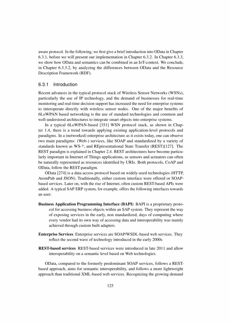
aware protocol. In the following, we first give a brief introduction into OData in Chapter6.3.1, before we will present our implementation in Chapter 6.3.2. In Chapter 6.3.3,we show how OData and semantics can be combined in an IoT-context. We conclude,in Chapter 6.3.3.2, by analyzing the differences between OData and the ResourceDescription Framework (RDF).
6.3.1 Introduction
Recent advances in the typical protocol stack of Wireless Sensor Networks (WSNs),particularly the use of IP technology, and the demand of businesses for real-timemonitoring and real-time decision support has increased the need for enterprise systemsto interoperate directly with wireless sensor nodes. One of the major benefits of6LoWPAN based networking is the use of standard technologies and common andwell-understood architectures to integrate smart objects into enterprise systems.
In a typical 6LoWPAN-based [351] WSN protocol stack, as shown in Chap-ter 1.4, there is a trend towards applying existing application-level protocols andparadigms. In a (networked) enterprise architecture as it exists today, one can observetwo main paradigms: (Web-) services, like SOAP and standardized by a variety ofstandards known as WS-*, and REpresentational State Transfer (REST)[127]. TheREST paradigm is explained in Chapter 2.4. REST architectures have become particu-larly important in Internet of Things applications, as sensors and actuators can oftenbe naturally represented as resources identified by URIs. Both protocols, CoAP andOData, follow the REST-paradigm.
OData [274] is a data access protocol based on widely-used technologies (HTTP,AtomPub and JSON). Traditionally, either custom interface were offered or SOAP-based services. Later on, with the rise of Internet, often custom REST-based APIs wereadded. A typical SAP ERP system, for example, offers the following interfaces towardsan user:
Business Application Programming Interface (BAPI) BAPI is a proprietary proto-col for accessing business objects within an SAP system. They represent the wayof exposing services in the early, non standardized, days of computing whereevery vendor had its own way of accessing data and interoperability was mainlyachieved through custom built adapters
Enterprise Services Enterprise services are SOAP/WSDL-based web services. Theyreflect the second wave of technology introduced in the early 2000s
REST-based services REST-based services were introduced in late 2011 and allowinteroperability on a semantic level based on Web technologies.
OData, compared to the formerly predominant SOAP services, follows a REST-based approach, aims for semantic interoperability, and follows a more lightweightapproach than traditional XML-based web services. Recognizing the growing demand
125

for exposing services to customers and partners as part of a networked industry, manyIT vendors have extended their offerings with OData support. In general, one observesa trend towards OData in many IT organizations. SAP, for example, makes its wholeBusiness Suite available through OData additionally to already existing APIs aimingtowards making OData the sole standard for all of its products. Windows Azure, thecloud platform of Microsoft, can be accessed through OData [205, 219] as well as theirERP offering Dynamics [39] among many others. Other than these examples, showingthe acceptance of OData in the ERP and the cloud sector, many more offerings availablethat can produce and consume OData [367].
The OData protocol was not designed to work with constrained devices in the firstplace. It was originally designed to work with more heavy-weight clients, like in com-municating enterprise systems or communication between an enterprise system and amobile phone. The OData standard defines two ways for data representation (sometimescalled serialization), from which one is rather heavyweight: ATOM/AtomPub [282]and JSON [98]. The two formats are used to represent the result of a service call. Theyare also used to model the service itself, using the common schema definition language.A more detailed overview into the data representation in OData is given in Chapter2.6.4.
Semantic modeling in OData follows a close-world assumption, where everythingis supposed to be known. Its entities (the objects to be modeled) and the relations arestored in the Entity Data Model (EDM). In the case of a temperate sensor, for example,an OData model would need to have the entities for sensors and temperature with aspecialization of TemperatureInCelcsius. Nonetheless, the entity model can be sharedamong parties.
The general concept shares some similarities with the Semantic Web our definitionof Linked Services. Concepts for mapping OData to the (RDF-based) semantic webexist. The data models can be described in EDM terms using the conceptual schemadefinition language (CSDL) [271]. A more detailed introduction into OData, with abroader overview of its data model can be found in Chapter 2.6.
6.3.2 OData on Wireless Sensor Motes
In the following we will, in Chapter 6.3.2.1, first briefly elaborate on possible deploy-ment options and then continue with discussing data representation in Chapter 6.3.2.2,followed by the protocol stack in Chapter 6.3.2.3.
6.3.2.1 Deployment Options
For exposing single IoT-devices or whole sensor networks towards enterprise systemswith OData several deployment options are possible. The two most common options areillustrated in Figure 6.2. In this section, we will discuss the deployment considerationsof implementing an OData-enabled system.
126

Enterprise System
OData stack WSN stack
(a) Intermediate OData Gateway
Enterprise System
(b) Direct access to single motes
Figure 6.2: Deployment Options
The first option is illustrated in Figure 6.2a: OData can be used to access wholesensor networks (Entity Model), with a gateway as entry point. The sensor networkitself communicates internally with a different protocol stack that is typically tailoredto low energy consumption or low latency. The application logic for making requestsand setting up the sensor network to satisfy a request resides in the gateway. The ODatagateway can be either a sensor node itself, or a platform with more computing power.
The second option is shown in Figure 6.2b. The enterprise system interacts directlywith single motes over the OData protocol. This pattern is usually applied when single-board sensor platforms or embedded devices are used. We will consider only thisapproach, as one of the main visions of the future Internet of Things is to be able tocommunicate with and directly address independent motes. The first approach is nodifferent from any other gateway or proxy approach, as the sensor network is completelyindependent from the enterprise communication. We will not explore this option further.Instead, we will only consider only scenarios where the motes themselves communicatethrough OData.
6.3.2.2 Data Representation
OData supports two representations: XML (as in ATOM) and JSON. An introductionto the OData data representation is given in Chapter 2.6.4.
We investigated both options, as the current standards up to OData v3 requirethat OData services must support the ATOM encoding and should support the JSONencoding. The upcoming v4 of the standard loosens those in favor of more lightweightclients, as it specifies that OData service must support at least one of the two.
In our experiments we included a compressed version of both XML and JSON.We opted to use general purpose compression algorithms. Previous research at theCDS working group by Dolfus and Braun [110] showed that standard compressionalgorithms have a quite decent compression performance, even compared to specialized
127
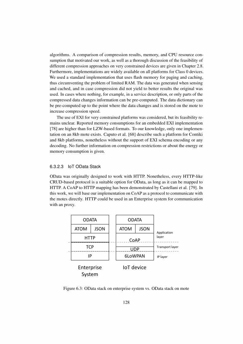
algorithms. A comparison of compression results, memory, and CPU resource con-sumption that motivated our work, as well as a thorough discussion of the feasibility ofdifferent compression approaches on very constrained devices are given in Chapter 2.8.Furthermore, implementations are widely available on all platforms for Class 0 devices.We used a standard implementation that uses flash memory for paging and caching,thus circumventing the problem of limited RAM. The data was generated when sensingand cached, and in case compression did not yield to better results the original wasused. In cases where nothing, for example, in a service description, or only parts of thecompressed data changes information can be pre-computed. The data dictionary canbe pre-computed up to the point where the data changes and is stored on the mote toincrease compression speed.
The use of EXI for very constrained platforms was considered, but its feasibility re-mains unclear. Reported memory consumptions for an embedded EXI implementation[78] are higher than for LZW-based formats. To our knowledge, only one implemen-tation on an 8kb mote exists. Caputo et al. [68] describe such a platform for Contikiand 8kb platforms, nonetheless without the support of EXI schema encoding or anydecoding. No further information on compression restrictions or about the energy ormemory consumption is given.
6.3.2.3 IoT OData Stack
OData was originally designed to work with HTTP. Nonetheless, every HTTP-likeCRUD-based protocol is a suitable option for OData, as long as it can be mapped toHTTP. A CoAP to HTTP mapping has been demonstrated by Castellani et al. [79]. Inthis work, we will base our implementation on CoAP as a protocol to communicate withthe motes directly. HTTP could be used in an Enterprise system for communicationwith an proxy.
TCP
HTTP
ATOM
ODATA
IP
UDP
CoAP
ATOM
ODATA
6LoWPAN
EnterpriseSystem
IoT device
JSON JSONApplicationlayer
Transport layer
IP layer
Figure 6.3: OData stack on enterprise system vs. OData stack on mote
128
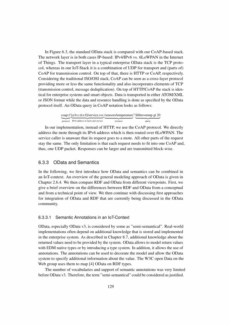
In Figure 6.3, the standard OData stack is compared with our CoAP-based stack.The network layer is in both cases IP-based: IPv4/IPv6 vs. 6LoWPAN in the Internetof Things. The transport layer in a typical enterprise OData stack is the TCP proto-col, whereas in our IoT-Stack it is a combination of UDP for transport and (parts of)CoAP for transmission control. On top of that, there is HTTP or CoAP, respectively.Considering the traditional ISO/OSI stack, CoAP can be seen as a cross-layer protocolproviding more or less the same functionality and also incorporates elements of TCP(transmission control, message deduplication). On top of HTTP/CoAP the stack is iden-tical for enterprise systems and smart objects. Data is transported in either ATOM/XMLor JSON format while the data and resource handling is done as specified by the ODataprotocol itself. An OData query in CoAP notation looks as follows:
coap://︸ ︷︷ ︸protocol
[a:b:c:d:e:f]/service.svc︸ ︷︷ ︸IPv6 address of mote and service
/sensors/temperature︸ ︷︷ ︸resource
? $filter=temp gt 20︸ ︷︷ ︸query
In our implementation, instead of HTTP, we use the CoAP protocol. We directlyaddress the mote through its IPv6 address which is then routed over 6LoWPAN. Theservice caller is unaware that its request goes to a mote. All other parts of the requeststay the same. The only limitation is that each request needs to fit into one CoAP and,thus, one UDP packet. Responses can be larger and are transmitted block-wise.
6.3.3 OData and Semantics
In the following, we first introduce how OData and semantics can be combined inan IoT-context. An overview of the general modeling approach of OData is given inChapter 2.6.4. We then compare RDF and OData from different viewpoints. First, wegive a brief overview on the differences between RDF and OData from a conceptualand from a technical point of view. We then continue with discussing first approachesfor integration of OData and RDF that are currently being discussed in the ODatacommunity.
6.3.3.1 Semantic Annotations in an IoT-Context
OData, especially OData v3, is considered by some as ”semi-semantical”. Real-worldimplementations often depend on additional knowledge that is stored and implementedin the enterprise system. As described in Chapter 8.7, additional knowledge about thereturned values need to be provided by the system. OData allows to model return valueswith EDM native types or by introducing a type system. In addition, it allows the use ofannotations. The annotations can be used to decorate the model and allow the ODatasystem to specify additional information about the value. The W3C open Data on theWeb group uses them to map [4] OData on RDF types.
The number of vocabularies and support of semantic annotations was very limitedbefore OData v3. Therefore, the term ”semi-semantical” could be considered as justified.
129

Before the introduction of annotations some vendors, for example, SAP had their ownsemantic extensions to express business logic.
Listing 6.1: Annotations: OData vendor specific extensions
<Property Name="temperature" Type="Edm.Int16" sap:unit="Celsius"/>
In OData v3, the concept of annotations was introduced. They were, similar tothe original SAP concept, unstructured information to store any kind of annotations,including semantics. As shown in Listing 6.2, terms and strings are used to expresssemantic relationships. The annotation is added to the description of the property.
Listing 6.2: Annotations: OData v3
<property name="temperature" type="Edm.Int16"><ValueAnnotation Term="Measures.Unit.Temperature" String="
Celsius"></property>
OData v4 enhanced the concept of annotations and made them first-class citizens inthe OData world. OData allows annotations both on a metadata level (Metadata annota-tions), as well as on an instance level (Instance annotations). Metadata annotations arevalid for the whole service. They can be attached, for example, to a property. Instanceannotations are used for just that instance of the return set.
Listing 6.3: Annotations: OData v4
<Property Name="temperature" Type="Edm.Int16"><Annotation Term="Measures.Unit.Celsius" />
</Property>
Different modeling options are possible. For example, the above could also beimplemented as a string.
Listing 6.4: Annotations: OData v4 - as string
<Property Name="temperature" Type="Edm.Int16"><Annotation Term="Measures.Unit" String="Celsius" />
</Property>
In addition, the annotations can be made available via hyperlinks. This means thateven the annotations and the semantic information can be made available as part of aHATEOS-driven engine.
Listing 6.5: Annotations: OData v4 - as path
<Property Name="temperature" Type="Edm.Int16"><Annotation Term="Measures.Unit" Path="sensorUnit" />
</Property>
130

<Property Name="sensorUnit" Type="Edm.String" />
Of course, different, and more complicated vocabularies can be build with anno-tations. A comprehensive introduction is given in the OData v3 [271] and OData v4[286] specifications.
With OData v4 [287] more vocabularies are introduced, which are interesting forIoT: for example, a core vocabulary that can be used to annotate the capabilities ofthe OData service. This is especially relevant for OData services that are used in theInternet of Things, as they allow specifying what a service running on a constraineddevice can actually do. For example, some capabilities of OData (i.-e. some queries)might not be supported or might be supported only in a limited scope. OData v4 alsosupports a measures vocabulary. The measures vocabulary is used to describe amountsand measured quantities. Obviously, this vocabulary is of special interest in the IoTdomain.
To sum up, prior to OData v3, vendor-specific extensions had to be used. Onlystarting with OData v3 did the protocol have capabilities to describe services seman-tically. OData v3 already supports relating things with each other (as RDF does) andquerying data (as SPARQL) does. It lacks (standardized) vocabularies though andoffers limited support of annotations. The situation changed with OData v4. It providesmore extensive support of annotations and started to introduce vocabularies. As soon asOData v4 use becomes more widespread and if some standard vocabularies evolve, itcould become the enterprise standard for semantically-enriched data services.
6.3.3.2 OData and RDF: A Comparison
We now briefly compare the properties of OData and RDF. Of course, they were createdfrom different backgrounds and with different underlying goals. Nonetheless, theyshare some key similarities which we will briefly discuss. An overview of the differentproperties of OData and RDF and their similarities and differences is summarized inTable 6.1. Understanding the differences is important to be able to compare LinkedUSDL for IoT and OData in a larger context. Linked USDL and Linked USDL for IoTare typical representatives of the RDF-based service description family.
OData and RDF share the same conceptual model based on an entity-attribute-value graph data model. OData prescribes a data representation format, while RDFdoes not. Typically, RDF is represented as N3, Turtle or more recently JSON-LD. Asdiscussed in Chapter 6.3.3.1, OData previously lacked – to some degree – semanticmodeling capabilities. One of the main issues interoperability faces is the availabilityof standardized vocabularies. Nonetheless, the number of vocabularies is increasing.
131

Property RDF OData
Model Entity-Attribute-Value Graph Entity-Attribute-Value GraphMain data represen-tation format(s)
Non mandatory: Mainlytriples (N3), Turlte, JSON-LD
ATOM (XML), JSON
Operations CRUD CRUDData storage Not mandatory, but RDF and
the development of triplestores are closely connected.Commonly, triple stores arethe backbone of RDF imple-mentations.
None mandatory, OData wasdesigned to be seen as an ab-stract interface to any type ofdata. OData coined the term
Extensibility Open world assumption Closed-world assumptionSemantics Semantic Annotations
(v3,v4), vendor specific (v2)inherent
Vocabularies many fewStandardization W3C OASIS
Table 6.1: OData vs. RDF comparison
6.3.3.3 OData and RDF/SPARQL
An early approach for integration of OData and RDF-encoded knowledge was presentedby Microsoft Research and DERI. They expose data stored within a RDF triple storethrough OData [163]. A generalized RDF to OData converter was developed. The basicschematics of the architecture is shown in Figure 6.4. The converter accesses the RDFdata through a SPARQL interface and maps it to OData. The mapping configurationwas stored in user-defined rule sets and not automated.
The rule-set generates both data-feeds for the actual data (services accesses) and themetadata that describes the service and the semantic information based on the originalRDF triple store.
Further research at SAP is currently underway that aims for integration of ODatainto RDF. Kirchhoff and Geihs [203] propose a semantic extension of the ServiceMetadata Document to make OData available for integration with the semantic web.They defined a mapping from the Entity Data Model (EDM), which is described withCSDL, to RDF graphs. Similarity to the Microsoft Research approach, but moreadvanced, templates are used for mapping.
For querying OData with RDF technologies Kirchhoff and Geihs also present aSPARQL interface for OData [204]. The general architecture of their proposed systemis shown in Figure 6.5. A client issues SPARQL queries to the system. The QueryEngine receives the request and evaluates it using the templates that are stored intheir service registry. In case the data exposed by one of the services is relevant for
132

RDF2OData ConverterEngine
Configuration
File
SPARQLendpoint
OData output
Figure 6.4: Overview of RDF2OData architecture [163]
Due to the complexity and frequent changes of the internal ERP database schema neither of these two approaches can be used. As explained in Section 3, the ontology that is the foundation of the ERP SPARQL endpoint must model the business object types, their properties and their relations among each other. The direct mapping as proposed by the RDB2RDF Working Group cannot be used because the business object types usually do not have a direct mapping in the database schema. Instead business objects are often distributed across several tables. These tables and their columns which represent the properties of the business objects often have none-descriptive names. Hence, the direct mapping approach would result in a very complex ontology with several concepts for most of the business object types. Although it is possible to define a customized mapping by using the R2RML this solution has several drawbacks as well:
The ERP database schema consists of several thousands of tables which are often difficult to understand. This makes it very complicated to define the mapping.
The fact that the business object types usually do not have a direct mapping in the database schema makes it even more difficult to define the mapping.
The database schema changes over time, i.e. it is not unusual that a new version of the ERP system has a different database schema than the previous one. Thus, a customized mapping based on the database schema would be valid only for a specific version. An adaption would be necessary for each new version.
Due to these reasons it is practically not feasible to manually define a mapping based on the database schema. A better solution is to place the SPARQL endpoint on top of existing ERP interfaces that allow the direct retrieval of business objects. This has several advantages:
The interfaces are far less complex than the database schema and they are well documented which simplifies the definition of the mapping.
The functions and services of the interfaces are assigned to business objects. Furthermore, they allow the direct retrieval of the data of the business objects. This simplifies the mapping to the corresponding business object concepts of the ontology.
A mapping defined with regard to a specific ERP version will be valid for many future versions as downward compatibility is guaranteed for a long period of time.
Functions and services released with a new version can be made available to the SPARQL endpoint easily by just adding a new mapping definition without changing the old one.
The SAP ERP provides several interfaces to access business objects. We considered the following: Business Application Programming Interface (BAPI), Enterprise Services (ES) and SAP NetWeaver Gateway. The BAPI is a set of remote function call (RFC) modules that are grouped according the business objects. BAPIs can be called from many different programming environments, e.g. ABAP, Java (SAP Java Connector), .NET (SAP Connector for Microsoft .NET). The Enterprise Service interface is
a SOAP/WSDL-based Web Service interface. Currently, the interface provides services for over 330 business objects of the SAP ERP system. New Enterprise Services are added if a business need is identified by the Enterprise Services Community. Downward compatibility is guaranteed for the Enterprise Services as well as for the BAPI. SAP NetWeaver Gateway is a new development framework that can be used to expose business object data as REST based services. Currently, it does not provide as many predefined services as the BAPI or the Enterprise Services and it is not available on many ERP systems. Therefore, we build our system on top of the Enterprise Services.
3. Architecture In this section we describe the main components of the system. Figure 3 shows the overall architecture of the semantic ERP layer (S-ERP Layer). The layer provides a SPARQL endpoint on top of the ERP system. It can be used by client applications to query the ERP system. A SPARQL query sent by the client is received by the Orchestration Engine (OE) where it is transformed into an internal data model. Based on the syntactic and semantic descriptions of the Enterprise Services stored in the Service Registry the Orchestration Engine determines the Enterprise Services that need to be called to answer the query. The OE sends the orchestration information to the Execution Engine which calls the corresponding Enterprise Services. The result is either forwarded directly to the Orchestration Engine which returns it to the client or, if reasoning is needed, it is forwarded to an RDF Adapter.
SAP ERP
Orchestration Engine
Execution Engine
Triple Store
SPARQL Processor
RDF Adapter
Reasoner
R
R
RService Registry
S-ERP Layer
R
Client Application
Figure 3: S-ERP layer architecture. The RDF adapter transforms the business object data into the RDF data format. Rule-based reasoning is provided by a reasoner that operates on the RDF data stored in the triple store. The actual SPARQL query sent by the client is executed by the SPARQL processor against the data in the triple store.
The ontology is the central component of the whole system as it determines the data that can be queried from the ERP system. It must reflect the business objects, their attributes and associations to other business objects. However, as the S-ERP layer uses the Enterprise Services to retrieve the data from the ERP system the ontology has to be aligned with the data model used by the Enterprise Services. This data model is based on the Global Data Types (GDTs) [9]. The GDTs are SAP-wide standardized data types derived from the Core Data Types as specified in the UN/CEFACT Core Component Technical Specification (CCTS) [1]. They are described in XML Schema and directly used by the Enterprise Services. Figure 4 shows the relation between the
175
Figure 6.5: SPARQL-OData-Layer architecture [204]
the successful evaluation of the query, the Query Engine creates an URI that is thenforwarded to the execution engine. The execution engine performs the actual call tothe OData service. The OData service responds with ATOM or JSON documents thatare transformed into RDF graphs (RDF Adapter). The RDF graphs can be used inrule-based reasoning engines (Reasoner). A SPARQL processing engine executes theSPARQL query against the data stored in the semantic data storage (triple store). Thefinal result is passed to the Query Engine which returns it to the client. The completearchitecture and its logical foundations can be found in [202].
133

6.4 Conclusions
In Chapter 1.3, we introduced our general idea of investigating a bottom-up and a top-down approach. We introduced a CoAP implementation and an OData implementationfor constrained devices. Furthermore, we discussed several properties of OData andrelated them to the needs of a semantics-aware enterprise utilizing IoT-devices. CoAPin conjunction with Linked USDL can be used to implement a bottom-up approach.OData, coming from the enterprise-world, can be seen as an top-down approach.
We presented our implementation of the Constrained Application Protocol (CoAP)on a reactive VM-based operating system (see Chapter 2.2). We implemented thebase CoAP specification, as outlined in RFC 7252 [353] and two extensions: block-wise transfer [352] and observe [162]. Implementing the CoAP protocol on a Class0 [54] (see Chapter 1.4) device exposes some specific challenges. First, we deal withvery constrained devices both in computing capabilities and memory. Especially, amemory-aware implementation of the options as defined by CoAP in its latest versions,needed some effort to reduce the number of processing steps without allocating toomuch memory. Previous versions of CoAP used linearly ordered options, which areway easier to handle on-mote, but consumed more bytes when transferred. Here thedesign of the CoAP protocol should be easier to implement in Class 1 (and above)motes. CoAP implementations for Class 0 devices should refrain from using too manyoptions.
In Chapter 4.7 we already mentioned the need of redirections to support linkingparts of a service description together. CoAP does not have this property at the moment.We therefore discussed four possible solutions: 3.xx message codes, CoAP options,Content Type and Data encoding. We concluded that, while the 3.xx family might bethe most desirable, currently the most promising solution is to move the problem to theapplication itself. In our opinion this is a gap in the standard that needs to be addressedin future CoAP releases.
We implemented all of our work in Java. Using Java was quite an advantage as everyteam member was able to start after a minimal ramp-up phase. While implementinga protocol like CoAP some downsides emerged: The CoAP specification, like mostprotocol specifications, assumes a C-like 8bit unsigned byte datatype or, more generally,the availability of unsigned datatypes. It was therefore not straightforward to implementthe specification and lead to some hard to track errors and unnecessary calculations andtype casts. We believe an embedded version of Java should support unsigned datatypesto ease implementation of such protocols.
We introduced an IoT stack for OData. Instead of using HTTP, the more recentCoAP protocol can be used. OData was used as a representative of a new class ofservice description languages. It follows a different approach than RDF-based servicedescription languages, such as Linked USDL for IoT. It combines semantics-awarenesswith a RESTful protocol that does not need external semantic annotations or extensions.Linked USDL for IoT separates the service description from the representation. There is
134
no representation prescribed and minimal data representations can be used. Furthermore,Linked USDL for IoT is better integrated into the semantic world, leveraging onsemantic technologies and linking well known vocabularies. The advantage of ODatais that it can be easily integrated into Enterprise systems without the need for anyadoptions. It is standardized and used by a large number of corporations. Existingtooling can be reused, as well as programming frameworks and libraries. OData followsa close world assumption. Semantic-annotations are possible and likely to be furtherextended in upcoming OData versions. The amount of vocabularies will most likelyincrease as well. OData does not need to stay in its ”silo”. OData and RDF-basedsemantics do not need to be mutually exclusive. First approaches for integrating ODatawith RDF exist.
OData responses are typically rather large, at least compared to what has been usedin the sensor network community so far. Compression helps reducing transmissiontimes and, thus, total energy consumption. As far as compression is concerned, basedupon previous research as discussed in Chapter 2.8, we opted for a standard compressionscheme. These have shown to work reasonably well compared to more specializedcompression algorithms. They work for both ATOM and JSON representations, as wellas any kind of data that might be collected by the system. Furthermore, they have shownlow computational and memory overhead, and, thus, are suitable for very constraineddevices. Moving away from very constrained devices to a platform with more memoryand computational power, the choice might have to be reconsidered.
Interoperability with enterprise systems is one of main arguments for using OData.On the downside, one has to stay within the ”closed world” of OData. OData currentlyoffers less semantic modeling abilities and was coined ”semi-semantic” by some people,because of its lack of integration into the semantic web. This seems to be justified forOData v2, but less justified for OData v3 and with OData v4, semantic annotations arefully supported. The situation on standard vocabularies also changes currently. ODatav4 already has some standardized vocabularies, for example, for core capabilities andmeasurements. Given the standardization power of the OData supporters within OASIS,the OData community could soon have its own set of standard vocabularies. This wouldenhances OData’s interoperability capabilities and, at some point, might enable thebreakthrough of semantic interoperability in enterprises.
135

136
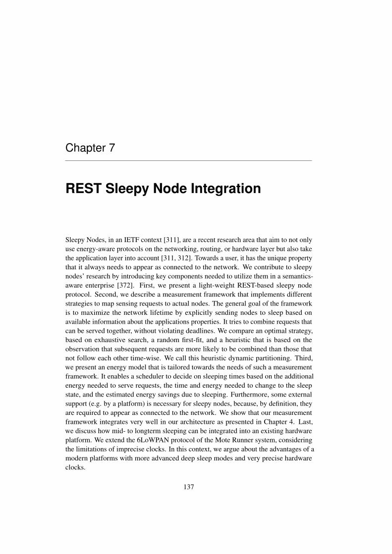
Chapter 7
REST Sleepy Node Integration
Sleepy Nodes, in an IETF context [311], are a recent research area that aim to not onlyuse energy-aware protocols on the networking, routing, or hardware layer but also takethe application layer into account [311, 312]. Towards a user, it has the unique propertythat it always needs to appear as connected to the network. We contribute to sleepynodes’ research by introducing key components needed to utilize them in a semantics-aware enterprise [372]. First, we present a light-weight REST-based sleepy nodeprotocol. Second, we describe a measurement framework that implements differentstrategies to map sensing requests to actual nodes. The general goal of the frameworkis to maximize the network lifetime by explicitly sending nodes to sleep based onavailable information about the applications properties. It tries to combine requests thatcan be served together, without violating deadlines. We compare an optimal strategy,based on exhaustive search, a random first-fit, and a heuristic that is based on theobservation that subsequent requests are more likely to be combined than those thatnot follow each other time-wise. We call this heuristic dynamic partitioning. Third,we present an energy model that is tailored towards the needs of such a measurementframework. It enables a scheduler to decide on sleeping times based on the additionalenergy needed to serve requests, the time and energy needed to change to the sleepstate, and the estimated energy savings due to sleeping. Furthermore, some externalsupport (e.g. by a platform) is necessary for sleepy nodes, because, by definition, theyare required to appear as connected to the network. We show that our measurementframework integrates very well in our architecture as presented in Chapter 4. Last,we discuss how mid- to longterm sleeping can be integrated into an existing hardwareplatform. We extend the 6LoWPAN protocol of the Mote Runner system, consideringthe limitations of imprecise clocks. In this context, we argue about the advantages of amodern platforms with more advanced deep sleep modes and very precise hardwareclocks.
137
7.1 Introduction
In addition to service-based interoperability one of the main issues in industrial use ofsmall battery-powered devices is energy saving. The integration of enterprise systemsand Internet-of-Things (IoT) devices based on semantically enriched protocols andservices enables IoT devices to act according to additional knowledge available on asemantic or application layer.
In the past, the problem of energy saving on the protocol-level [59], routing [178,345], in the MAC layer [13, 400, 385], or on the actual hardware [309, 304, 300] hasbeen studied extensively. While the MAC-layer or routing support for sleepy nodes(or sleep states) performs quite well, these functionalities are typically unaware of anytiming or operational aspects of the application layer and, therefore, cannot leverage onthat.
In the following, we introduce an application-layer REST sleepy node implementa-tion and measurement framework for saving energy [ 372]. We define, based upon theIETF definition [311], a sleepy node as follows:
A sleepy node is a node that may sometimes go into a sleep mode to saveenergy and that temporarily suspends all protocol communication. A sleepy nodewill otherwise remain in a fully powered-on state where it has the capability toperform any protocol communication. To the user, the sleepy node always appearsas connected, thus being part of the network.
Sleepy nodes that perform mid- to longterm sleeping can be used whenever thesesleeping times can be calculated by the application layer. In the following, we will lookinto a monitoring framework with soft real-time constraints. Usually, the design spaceof real-time applications is divided into three disjunctive classes [356]:
Hard real-time: A deadline is called hard, if the consequence of not meeting it is afailure and there are potentially severe consequences.
Firm real-time: A deadline is called firm, if the data produced ceases to be useful assoon as the deadline expires, but the consequences of not meeting the deadlineare not severe.
Soft real-time: A deadline is called soft, if it is not hard or firm and the utility of theresults decreases over time after the deadline expires. Compared to a hard real-time system, in a soft real-time system the miss of a deadline has no catastrophicconsequences. The data produces is still to some degree relevant, even if thedeadline has expired.
We are solely considering near real-time IoT systems [289] with soft quality ofservice requirements. Most enterprise applications that are part of the IoT have soft real-time requirements. In many cases, the data has some value even when it is late. Hard
138

real-time applications are not considered in this work. The delays and unpredictability ofover-the-air transmissions make hard real-time difficult to achieve [83], if the acceptabledeadlines are small. Korber et al. [213] and Lill/Sikora [237] report success under idealconditions in the 5ms to 8ms hard-real requirements. An overview by Paavola et al.[290] concludes that current wireless solutions, such as IEEE 802.11, IEEE 802.15.1,IEEE 802.15.4 and ZigBee are inapplicable for hard real-time applications with triggertimes around 5ms. Nonetheless, such applications can rarely be considered as part ofthe Internet of Things. Moreover, it is even more unlikely that they can profit from mid-to long range sleeping.
We will build on the application scenario as introduced in Chapter 4.6.2. Theimplementation is the monitoring of goods throughout the supply chain. For example,a container may be monitored very infrequently while being transported in a cargoship, more frequently while staying at a harbor and again less frequently while beingtransported in a truck.
In the following, we first present the application REST API that can be used to puta node to sleep. To comply fully with the definition of a sleepy node, we need someplatform support. We describe a possible platform in Chapter 7.3. The platform needsto determine if there is a potential energy consumption benefit in putting a node to sleep.For this we propose an energy model in Chapter 7.4. Next, as a second perquisite forthe successful implementation of the platform we need to adopt the network layer. Weexplain our modifications to the MRv6 protocol in Chapter 7.5. Finally, we put all thepieces together and present a measurement framework that can be used as scheduler ina sleepy node aware platform.
7.2 REST API
The REST API for accessing the sleepy node functionalities is kept simple and light-weight. It consists of a resource called sleepy that each node has to support and onlytwo operations. The first operation is for putting a mode to sleep. The second operationis for retrieving its status. The resource and the operations are shown in Table 7.1. Wesupport a JavaScript Object Notation (JSON)[60] representation with the parametersas key-value pairs. We decided against using CoAP options, which would have hadthe advantage of being more compact as they are stored in the message header itself.Nonetheless, such a design would be tightly coupled to CoAP. The use of specializedresources allows easier integration into non CoAP REST IoT-systems, like those builton top of HTTP.
The get statement is special in some sense. In case of an accessible node it canreturn status information, like the next scheduled sleep period or the time already spentsleeping. If the mote is sleeping, it can, for obvious reasons, not answer the request. Inthat case platform support is needed. It lets the node appear connected to the networkand replies to the request instead of the node.
139

Main Resource: sleepy
Op Parameter Description
POST duration Puts a node to sleep for a given amount of time (in ms)GET duration
stateReturns the remaining sleep time or the state of the node.
Table 7.1: Sleepy Nodes: REST API
7.3 Integration of Sleepy Nodes into the Enterprise Inte-gration Platform
To comply fully with the previously given definition of a sleepy node, some supportof an external system is needed. According to the definition of a sleepy node, to theuser the node has to always appear as connected. Operations on the mote, therefore,need support if the node is sleeping. This can be achieved with an external integrationplatform such as the one we described in Chapter 4. We will now describe how suchsupported can be implemented as part of our integration platform.
The high-level schematics of the needed new components are shown in Figure 7.1.The new components integrate seamlessly into our architecture (as described in Chapter4). The following additions are made: A command and control (C&C) module issuescommands, such as sleep requests, to the sensor nodes. As a sleepy node always appearsconnected to the network, the platform acts as a transparent proxy, intercepting callsto sleepy nodes and returning the state and/or cached values in case they are sleeping.As our sleepy node implementation is to be used as part of a semantically-enrichedIoT platform, the state of the sensor network (in this particular case, sleeping or notsleeping) is stored as part of the sensor network description.
The following three main interactions between a client requesting data and the nodethat provides this data are possible: (1) The node is not sleeping and the client candirectly work with the node. (2) The node is sleeping and a client requests data. Therequest is intercepted by the transparent proxy. It returns the requested data togetherwith the age of the information and an indication that it came from a proxy. The clientcan now either work with this data or query the sleeping time of the node and schedulea new query later on. (3) The node is sleeping, but a request that cannot be handled bythe proxy arrives. This could be the case as no data has been cached, because the noderequested that this particular resource is not to be cached, or because it is a request thathas side effects. In such cases, the proxy will indicate the unavailability of the node andthe client has to query about when the node will be available again and schedules itsqueries accordingly. In each case, the data can then be retrieved either by polling or viaa notification (e.g. CoAP observe)
As outlined in Chapter 7.3, we are working with semantic descriptions instead of aresource directory [350]. Furthermore, we envision the use of an integration platform
140
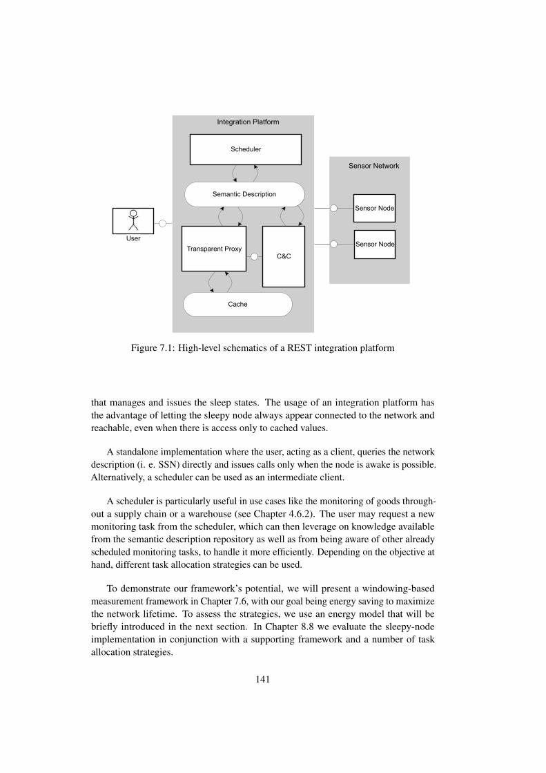
1 / 1
User
Sensor Network
Sensor Node A
Sensor Node B
Integration Platform
Semantic Description
Transparent Proxy
Cache
C&C
Scheduler
Figure 7.1: High-level schematics of a REST integration platform
that manages and issues the sleep states. The usage of an integration platform hasthe advantage of letting the sleepy node always appear connected to the network andreachable, even when there is access only to cached values.
A standalone implementation where the user, acting as a client, queries the networkdescription (i. e. SSN) directly and issues calls only when the node is awake is possible.Alternatively, a scheduler can be used as an intermediate client.
A scheduler is particularly useful in use cases like the monitoring of goods through-out a supply chain or a warehouse (see Chapter 4.6.2). The user may request a newmonitoring task from the scheduler, which can then leverage on knowledge availablefrom the semantic description repository as well as from being aware of other alreadyscheduled monitoring tasks, to handle it more efficiently. Depending on the objective athand, different task allocation strategies can be used.
To demonstrate our framework’s potential, we will present a windowing-basedmeasurement framework in Chapter 7.6, with our goal being energy saving to maximizethe network lifetime. To assess the strategies, we use an energy model that will bebriefly introduced in the next section. In Chapter 8.8 we evaluate the sleepy-nodeimplementation in conjunction with a supporting framework and a number of taskallocation strategies.
141

7.4 Energy Model
The measurement framework needs to be able to determine if there is any benefit insending a node to sleep. For this, it relies on an (analytical) energy model that we willintroduce here.
7.4.1 Introduction
Energy estimations, if not measured directly, are typically made by estimating the timean application stays in a specific energy mode or by counting the number of messagessent and received. Given that the radio is often the most energy-consuming part ofan IoT device, the message counting approach is considered good enough for manyapplications. Often, a three state radio model is assumed in which listening (receive),transmit and sleep states are considered [179, 161, 400, 302]. Models with higher levelsof sophistication also consider the states of the CPU or of specific sensing devices[341, 200, 346].
7.4.2 Energy Model
We use a hybrid approach, in the sense that we consider the duration spent in someenergy modes (idle and sleep) and the energy needed to react to different events(processing, sending and receiving). It is more accurate than message counting, but lessaccurate than measuring hardware states. Given the warm-up and cool-down times ofdevices, the presented strategies will look for large savings. Therefore, the objectiveof the energy model is not to get highly accurate solutions, but to define situations inwhich sleeping is more energy efficient than idling.
For every node, we distinguish between the following modes, each with a differentlevel of power consumption:• Protocol Idle: The node is connected to the network and participates only in
required communication protocol activities.• Protocol Sleeping: The node does not participate in any communication protocol
activity. The nodes’ radio is turned off. Infrastructure support is needed to makea sleepy node appear reachable to users.• Sensing: The node is collecting data from its sensor• Computation: The node performs computations• Communication: The node is transmitting or receiving application data packets
through its radioTo present our model properly, we first make the following assumptions and defini-
tions: Esense, the energy consumed by a sensing request, and Esleep, the energy neededfor processing and executing a sleep request, have negligible variance. Packet payloadsdo not vary considerably either. We call the amount of energy spent for receiving onepacket and then transmitting one, Ecomm. In protocol idle, a node is only consuming(on average) power Pidle for necessary protocol activity. Similarly, in protocol sleeping
142
a node is consuming constant power Psleep. Psleep and Pidle should not be confusedwith the CPUs idle or sleep energy states.
We can now express an approximation of the energy En consumed on node n withspecific numbers of requests m, and the duration a node n stays in a specific state tnstateas:
En = tnidle · Pidle + tnsleep · Psleep︸ ︷︷ ︸time based
+mnsense · Esense +mn
sleep · Esleep +mncomm · Ecomm︸ ︷︷ ︸
event based
Pidle is determined by the lower-layer communication protocol. In a beacon-basedprotocol (like MRv6) it depends on the number N of connected edges, namely thenumber of neighbour nodes it is connected to:
Pidle = P baseidle +N · Pneighbour
idle
where P baseidle is the power consumed by participating in the communication protocol
regardless of the number of connected nodes (neighbours) and Pneighbouridle is the extra
power required for each connected node.It is important to differentiate between time-based and event-based energy and
power consumption. The relationship between time-based and event-based is as follows:Psleep is time-based, while Esleep is event-based. Esleep is the energy needed to send anode to sleep, wake it up again, and reattach it to the network. The energy consumedbetween going to sleep and waking up is tnsleep · Psleep.
7.5 Implementation of Mid- and Longterm Sleeping in MRv6
In the following, we will briefly introduce how we extended MRv6 [180], the 6LoWPANimplementation that ships with Mote Runner, to support mid- and longterm sleepingperiods. A brief introduction into 6LoWPAN is given in Chapter 2.3.2. The MRv6protocol is described in Chapter 2.3.3. The extension of MRv6 came with somechallenges that we had to overcome. The main challenge was to wake a node up beforeit was needed so that it would be available on time, taking into account the time it needsto attach to and leave the network as well as imprecise drifting clocks. First, we presentour modifications and extensions of MRv6 in Chapter 7.5.1. Then we go on to discussclock-drift in Chapter 7.5.2.
7.5.1 MRv6 Extensions for Sleepy Node Functionality
In order to support the application-layer sleepy node protocol, we had to extend theMRv6 protocol to enable the sleep states. As discussed in Chapter 7.4.2, the MoteRunner VM decides in which states the devices go. Therefore, we had to design theprotocol so that it stops executing even the MAC layer protocol. This enables the Mote
143

Runner system to put the radio device (among others) into sleep mode. The upper layerprotocol had to be modified such that the disassociation functionality of the originalMRv6 protocol does not query the children nodes, as they are unable to answer in aplanned deep sleep (protocol off) state.
Every (non-edge) mote that is loaded with the MRv6 component alternates betweenparent and child roles. Both roles keep track of their own state, reflecting the associationor communication stage they are currently in. Either may change several states withina single communication period. Each of these states has several expectations on thebehavior of the counterpart (parent or child) that we had to consider.
After a mote has been successfully associated with a parent, it starts participating inthe super-frame (see Chapter 2.3.3). At the beginning of the communication period themote adopts the child role in STATE CHILD RECEIVE BEACON. It schedules a radioreceive operation in order to listen for a beacon from its parent. The timestamp when thebeacon is expected to arrive is calculated by adding BEACON INTERVAL MILLIS tothe timestamp of the last received beacon. If the node is sleeping, none of this happens.The node cannot act as parent for its children and the children cannot communicatewith the parent.
Our sleeping functionality is exposed to Mote Runner applications as an MAC layerinterface. Any application running on the mote can put it to sleep for m millisecondsby calling Mac.scheduleSleep(ms). The MAC layer will then calculate the sleepingtime for the radio and then instructs the child-part (see Chapter 2.3.3) of the MRv6 layerto prepare for sleeping by also saving the timestamp that the next beacon is expected bycalling the newly introduced function Child.handleSleepRequest, so that it does nothave to go through the energy-costly and time-consuming procedure of reassociatingwith its parent afterwards (see Chapter 2.3.3.3 for the association process). First, thenumber of communication periods (π) that the requested sleeping time amounts to iscalculated:
π =
⌊msSleep
BEACON INTERV AL MILLIS
⌋Then, π beacon intervals are added to the timestamp of the last received beacon to formthe next timestamp that we will be listening to for a parent beacon:
nextBeaconTs =
lastBeaconTs+ π ·BEACON INTERV AL MILLIS (7.1)
After ensuring that there are no more pending packets to be transmitted by the mote,the MAC layer switches the radio off and sets a timer callback that will go off afterthe sleeping duration is over. The total time that the timer will count is calculated bysubtracting an offset from the total requested sleeping time, in order to compensate forthe radio state switches overhead and the mote wake-up (tovh) time.
144

wakeUpTs =
lastBeaconTs+ π ·BEACON INTERV AL MILLIS − tovh (7.2)
Furthermore, clock drift has to be considered. We will take a closer look into clockdrift in the next section.
7.5.2 Clock-Drift Considerations
The clock on most platforms is rather inaccurate and might drift over time. This meansthat two clocks on two nodes might not run at the exact same speed compared to eachother. The clock drift problem, although a major issue in many distributed algorithmsfor WSNs, is not as dramatic in a coarse-grained sleepy node implementation as ours,as no exact timing is necessary. We only have to ensure that the node is awake at agiven time. In sleeping periods in the magnitude of minutes and hours the impact ofwaking up motes some seconds before it is actually needed is negligible, comparedto the savings of long term sleeping. Nonetheless, we want to keep the extra energyneeded to compensate the clock-drift small.
Clock drift is measured in parts per million (ppm). Nowadays, a typical (noncompensated) crystal clock has a drift of around 20ppm [63]. Nonetheless, boards thatare more recent sometimes already have compensated crystals. The IEEE 802.15.4standard specifies a maximum drift of 40 ppm [184]. 20ppm translate to
Dpercent =Dppm
106∗ 100
=20
106∗ 100, forDppm = 20
= 0.002%
(7.3)
So, given one day with 86400 seconds, the expected clock drift per day is 1.78seconds, or around 400ms for a 10 hour period. As shown in Maroti et al. [ 248] mostclocks lag behind in time. As a consequence, the drift makes them timeout earlierinstead of too late. We will see later on (Chapter 7.6) that in the window task allocationscheme we are using, all nodes wakeup periodically at the beginning of a window.We assume window sizes in the range of multiple hours as an absolute maximum.Therefore, the expected clock drift is within a range that can be handled by the protocolwithout too much additional energy waste while waiting for the beacon.
Recent platforms come with more precise clocks. The Waspmote Pro platform,for example, uses the DS3231 [255] from Maxim Integrated. It is a highly accuraterealtime clock with an integrated temperature-compensated crystal oscillator (TCXO).It has an accuracy of only +-2ppm. In common temperature ranges its accuracy is evenclose to 0ppm. Figure 7.2 shows the drift ppm (delta frequency) of a DS3231 compared
145

Figure 7.2: MAXIM DS3231 drift [255]
to crystals that are not temperature compensated. Therefore, on the Waspmote Proplatform, the clock drift we have to compensate for can be calculated as follows:
Dpercent =Dppm
106∗ 100
=2
106∗ 100, forDppm = 2
= 0.0002%
(7.4)
These bounds can be improved by sophisticated estimation schemes that can beplugged into our implementation. Brzozowski et al. [63] investigated clock driftbehavior with typical MicaZ motes by applying drift prediction based on samplesgathered during runtime with moving average and linear regression algorithms.
Furthermore, to increase accuracy (thus sacrificing energy) the motes could turn onin intervals and synchronize with the global time base (beacons). Maroti et al. [248]have shown that in MicaZ modes, which can be considered similar to IRIS or WaspmotePro, linear regressions models can be used to predict the clock drift. In experimentswith lengths of 8 hours and 18 hours, the average absolute error was 2.24µS in thefirst experiment and 1.48µS in the second. The maximum absolute error was 8.64µsin the first experiment and 6.48µS in the second. Dai and Han implemented a similarapproach as part of their TSync protocol [99].
146

If there is significant clock drift, after waking up, the mote might start listening forits parent beacon either sooner or later than it actually arrives. In the first case, therewill be an extra energy overhead, proportional to the clock drift value, as this is the timethat the mote keeps its radio on waiting for the parent beacon redundantly. In the lattercase, the beacon we aimed for might be missed. Therefore, the mote will again have towait with its radio on, until the next parent beacon arrives. In the worst scenario forboth cases, the time that the mote spends with its radio unnecessarily on, will be equalto a whole beacon interval.
To reduce the possibility of loosing the parent beacon in the case of positive clockdrift, we can wakeup one or two intervals earlier, by subtracting a value θ. Furthermore,we need to account for the overhead caused by waking up and turning the radio onagain (tovh).
nextBeaconTs = lastBeaconTs
+ (π − θ) ·BEACON INTERV AL MILLIS
− tovh − tdrift(7.5)
There is a tradeoff when calculating good safety offset values that ensure that thenode wakes up before the targeted beacon and can join the network quickly: If weuse a bigger offset than needed, energy is wasted unnecessarily. But, if the offset isnot big enough to cover the potential drift, then the radio will have to stay on for awhole beacon interval, which is even worse. If the clock drift magnitude, as well as anapproximation of the average sleeping time that we expect to be requested are available,we can calculate a good safety offset as follows:
tdrift = tsleep · pdrift (7.6)
For example, in case we rarely expect to request a mote to sleep for more than 2500seconds and the measured clock drift is less than 2ppm, then by applying the aboveformula we get a 5ms safety offset.
In case of even lengthier sleep durations when large clock drifts are present, thedelay until the mote becomes responsive again might even exceed one beacon interval.Regardless of the effect on energy consumption, it has to be accounted for during thehigher-level sleeping time calculation.
When the sleep timer expires, the radio is switched back on and the mote adopts thechild role again, but this time starting in a new state that we added to the MRv6 statemodel: STATE CHILD SYNC BEACON. This state is identical toSTATE CHILD RECEIVE BEACON, except for the fact that it listens to the globalsuperframe to get in sync with the network again.
The sleep routine was designed to be invoked from the application layer, so that themote may offer a REST go-to-sleep service.
147
7.6 Measurement Framework
We introduce a measurement framework that solves a soft real-time task allocationproblem in a time-sliced (windowed) environment. We present three windowingbased task allocation (WBTA) strategies that map sensing requests to actual nodes.The proposed system shows the potential of a centralized sleep planning system byleveraging knowledge available at the application layer. The objective of the WBTA isto measure the entities at the required intervals, while aiming for an enhanced overallnetwork lifetime. We first give a detailed problem formulation in Chapter 7.6.1. Wethen introduce the task allocation strategies in Chapter 7.6.2. Next, in Chapter 7.7, weexplain the dynamic partitioning heuristic in a step-by-step example.
7.6.1 Problem Formulation
We assume a given static WSN topology and a list of entities that need to be measuredon defined time periods. These measurements can only be performed by defined sensorsets. Our main objective is to generate a close-to-optimal (”best effort”) queryingschedule that accommodates all given entity measurements, considering latency andenergy saving requirements. We defineS to represent the set of all sensors andE to bea set of entities, whose properties we want to monitor over time. First, we introduce thefollowing terms as part of our notation:
• Measurement: A measurement for an entity is a defined period in time (times-tamp and time tolerance) at which a measurement should be performed. Morethan one sensor may be eligible to perform it.
• Query: A query is a specific request to a sensor of the WSN to perform ameasurement. It may combine more than one measurements, as long as they arewithin time constraints and the assigned sensor is eligible to perform all of them.A query can be seen as an instance of one or more measurements.
Furthermore, for each entity ei ∈ E, we define the tuple (S, ω, δ) with
• S: S ⊂ S set of sensors that can measure the property of the entity
• ω: time period between subsequent measurements
• δi: the time tolerance within which a measurement is acceptable
We leverage on the high-level sleeping services, as introduced in Chapter 7.3, takinginto account the period ω, the tolerance δ, and the set of possible sensors S, to sendnodes into a sleep mode in order to save energy and achieve an enhanced networklifetime. A visualization of the scenario is shown in Figure 7.3. In the illustration,there are four nodes in the network (N0,N1,N2,N3) and three entities (E1, E2, E3)representing some goods to be monitored . E1 is in the sensor range of nodes N1 andN2. E2 is in the range of the nodes N3 and N1. E3 is only in the range of node N3.
148

Measurements
Queries
Tolerances(soft-real timeSystem)
Time ->
Window of length L
…
M1M2 M3
M4
E1 E2 E1 E3Entities
E1
E2
E3
N0
N1
N2
N3
N1:M1+M2 N2:M3 N3:M4
Every node wakes at window end
N1
N2
N3
Node is sleeping
Node awake to execute query 3
Figure 7.3: Measurement Framework: Illustration of the problem formulation
We assume that within the first window four measurementsM1, M2, M3 and M4 haveto be performed. M1 and M3 measure a property of E1. M2 measures a property ofE2 and M4 measures a property of E3. Each of these measurements has a toleranceassociated to it. The tolerances of M1 and M2 overlap, so the system could decide tocombine the two measurements into one actual query for node N1. The tolerances ofM3 and M4 overlap as well, but there is no common sensor. So, no decision has to betaken and M3 is mapped to a query of N2 (in this particular example, N1 could alsohave been selected). M4 is realized as query to N3. The resulting sleeping times areshown in the bottom left corner. In the beginning all nodes can sleep, then N1 needsto be awake to answer the query. It then can go to sleep again. Later, the remainingtwo queries have to be performed. Node N2 awakes to execute the second query and,finally, N3 will respond to its query.
7.6.2 Implementation of the Windowing-based Task Allocation Frame-work
In the following, we present the implementation of the WBTA and the task allocationstrategies.
The scheduling task can be roughly expressed as mapping a set of required mea-
149

surements to a sequence of scheduled queries. Our base scheduler uses a priority queryqueue (soonest timestamp first).
There is no explicit sleeping schedule. The sleeping requests are issued immediatelyafter the sensing queries have been completed. Calculation of the sleeping time for eachnode is performed by the scheduler as follows: The scheduler examines the queriesqueue, searching for the soonest timestamp where the node will be needed next eitherfor sensing or for communication. It then calculates the time interval from the currenttimestamp to this timestamp and subtracts a communication overhead. This is themaximum duration that the node can be allowed to sleep. Sleeping is omitted if thisduration is less than a defined threshold, where the energy overhead for sleeping isbigger than the gain. The sleeping times are always constrained by the window length.At the end of every window, all nodes in the network are awake.
The basic querying loop is shown in Algorithm 1, where the sleeping times calcula-tion is provided by the procedure CalcSleepTime.
The scheduling occurs in time windows of length L and is described in Algorithm2. At the beginning of each window w, Mw, the set of measurements that have to beperformed within this particular window, is calculated. Procedure CalcWindowQueriesis then called to map these measurements to a queue of queries. We present a numberof different strategies for this in Chapter 7.6.3.
In order to balance the power load over the nodes, we use a control policy based onpenalties for their utilization. We evaluate the sensors used for a measurement fromthe set of possible sensors, according to their expected effect on the energy footprint ofthe whole network. The penalty pn for each sensor Sn is calculated as the quotient ofthe average energy (m) over all nodes by the nodes’ residual energy (εnres). We use thepenalty to prevent over-utilization of one sensor to increase the network lifetime.
εnres = εninit − εn, ∀n ∈ Spn =← m
εnres,∀n ∈ S (7.7)
A penalty with a value larger than 1 means that the respective node has alreadyconsumed more energy than its counterparts. Further selections of this particular sensorwill result in an even higher utilization and, thus, in larger penalized costs. This willcause the scheduler to avoid choosing that node in favor of one that yields lowerpenalized cost.
Using the aforementioned penalty rule when choosing a sensor has two mainadvantages:
• Modeling of heterogeneous networks with different initial energy reserves fordifferent nodes is possible.
• As a nodes’ energy residual approaches zero, the denominator becomes verysmall, effectively yielding a very high penalty for the utilization of the node.
150

Algorithm 1 Base querying loop
1: while true do2: NEWWINDOW
3: for all n ∈ S do4: tnsleep ← CALCSLEEPTIME(n)
5: Issue sleep request for tnsleep on node n6: end for7: while QueryQueue not empty do8: nextQuery← QueryQueue.remove()9: wait until timestamp of nextQuery
10: execute nextQuery11: for all nodes that were used do12: tnsleep ← CALCSLEEPTIME(n)
13: Issue sleep request for tnsleep on node n14: end for15: end while16: end while
1: procedure CALCSLEEPTIME(n)2: for all q ∈ QueryQueue do3: if q uses node n then . either for sensing or for communication4: tdiff ← q.ts− tsnow5: twind ← windowEnd− tsnow6: tsleep ← min(tdiff , twind)− tcomm
7: if tsleep ≤ tthreshsleep then8: return tsleep9: else
10: return 0
11: end if12: end if13: end for14: end procedure
Hence, any choice that risks a node being depleted will be harshly penalized and,thus, avoided.
The calculation of these penalties is done as part of Algorithm 3. EvalQueries isgiven a query queue as input and it returns an energy cost for its potential realization.Calling SimulateConsumption will produce the states we expect the networks’ nodes tobe in, after executing the given queries within the current window.
GetEnergyMap is then called to provide the energy that has been consumed oneach sensor within the windows time interval according to these states. GetEnergyMapcalculates the consumed energy using the linear energy model and scaled with the
151

Algorithm 2 New Window and penalty update1: procedure NEWWINDOW
2: windowStart← windowEnd . previous window’s end3: windowEnd← windowStart + L4: UPDATEPENALITES
5: Mw ← {m ∈M : windowStart ≤ m.ts < windowEnd}6: QueryQueue←CALCWINDOWQUERIES(Mw)7: end procedure1: procedure UPDATEPENALTIES
2: ~ε← GETENERGYMAP(0, currentT imestamp)3: m← mean(~ε)
4: εnres = εninit − εn,∀n ∈ S . εninit indicates the initial energy reserve of sensorn
5: pn ← mεnres
,∀n ∈ S6: end procedure
penalty vector ~p. The penalties are updated at the beginning of each window, as shownin procedure UpdatePenalties.
Algorithm 3 Base Evaluation of Queries1: procedure EVALQUERIES(Q)2: SIMULATECONSUMPTION(Q)3: ~ε← GETENERGYMAP(windowStart, windowEnd)4: penalizedEnergy ← ~ε · ~p5: return penalizedEnergy6: end procedure
7.6.3 Scheduling Strategies
In the following, we present three strategies for scheduling the tasks within a window:an exhaustive strategy (Chapter 7.6.3.1), a memoization strategy (Chapter 7.6.3.2)and first fit (Chapter 7.6.3.3). The memoization strategy, as we will show, performsonly slightly worse than the exhaustive strategy. The exhaustive strategy, also knownas exhaustive search or bruteforce, guarantees finding the optimal solution for theclustering problem, with respect to our given window and query evaluation system. Ithas exponential complexity and works only for small problem sizes within reasonabletime bounds. The first fit strategy tries to compensate for overusing power resources byrandomly choosing a sensor, without any optimizations or combinations.
For every window w, a set of measurements Mw that are to be mapped to queriesis given. Consider an arbitrary partition of Mw, consisting of a family of sets calledclusters C, with
152

⋃C = Mw, 0 /∈ C,∀C1, C2 : C1 6= C2 → C1
⋂C2 = 0 (7.8)
We call the partition C valid if all Ci ∈ C can be mapped to queries. For a clusterCi to be mapped to a query, the following constraints need to be satisfied:
1. There is at least one sensor eligible to perform all measurements.2. There is an overlap of the time tolerance intervals among all of its measurements.In order to map a cluster that fulfills the above constraints into a query, we extract
a common timestamp and sensor for it. The common timestamp is calculated as themid-point of the common intersection of the time tolerance intervals of all the clusters’measurements. The sensor selection depends on the strategy and is described in therespective sections. We will refer to the above conditions as time tolerance and sensorconstraints, respectively, in the context of combining measurements into queries.
7.6.3.1 Exhaustive Strategy
The optimal solution for the clustering problem, within our windowing and querysystem, is applying an exhaustive approach (backtracking with constrained satisfaction).An exhaustive approach considers all possible partitions of the set Mw and evaluatesthem. The exhaustive approach is outlined in Algorithm 4. First, all possible partitionsare calculated and then each one is evaluated. The evaluation (and sensor selection) inprocedure EvalPartition is performed as follows: The clusters are examined in reversechronological order. First, the intersection of the sets of eligible sensors of all themeasurements is calculated. Afterwards, for every sensor in the resulting set, a queryis constructed and evaluated according to its energy profile in procedure EvalQueries(as defined in Algorithm 3. The sensor that yields the lowest penalized energy cost isselected and the resulting query is added to the queries queue. After all clusters havebeen mapped to queries, the resulting query queue is evaluated and the outcome isreturned. 1
The exhaustive approach has exponential time complexity, as the total number ofpossible partitions for a set of n measurements is the Bell number2 Bn =
∑∞i=0
Bii! n
i =
een−1. In practice, it may only be applied to small windows and, thus, will only be used
for benchmarking.
7.6.3.2 Dynamic Partitioning
In the following, we present an alternative to the exhaustive approach. Instead ofconsidering all possible partitions, we order the measurements Mw according to theirtimestamps and check only the ones that combine neighboring measurements using agreedy strategy. It calculates a local optimum and never reconsiders its choice. This
1This is equal to the cost that was returned by the evaluation of the sensor selected for the last queryadded. Therefore this second evaluation need not be actually done.
2Named after Eric Temple Bell, the Bell numbers count the number of partitions of a set. Bn countsthe number of different ways to partition a set of n elements
153

Algorithm 4 Exhaustive Window Queries Calculation1: procedure CALCWINDOWQUERIES(Mw)2: SPw ← all possible partitions of window measurements set3: Pbest ← argminP∈SPw
EVALPARTITION(P,Mw)4: return generated queries for partition Pbest
5: end procedure1: procedure EVALPARTITION(Pw, Mw)2: Qw ← empty queue3: for all cl ∈ {Pw sorted backwards} do4: Mcl ←Mw(cl) . get measurements in this cluster5: ts← mean timestamp over Mcl
6: Scl ← {∩(S ∈Mcl)} . ∩() represents reduction with intersection7: sbest ← argmins∈Scl
EVALQUERIES( [ new Query(ts, s, Mcl) , Qw ] )8: Qw.add(new Query(ts, sbest, Mcl))9: end for
10: return EVALQUERIES(Qw)11: end procedure
problem can be solved by applying memoization [ 96]. We call this heuristic dynamicpartitioning.
Next, we briefly present the main steps of this strategy: The approach is shownin detail in Algorithm 5. As we are following a memoization approach, we examinepreviously solved subproblems and combine their solutions during the construction of a|Mw|x |Mw| matrix representing subpartitions. The upper triangular part of the matrix,excluding the diagonal, is not used. An illustration of such a matrix can be seen inTable 7.2. Within the lower triangular part of the matrix, the (x,y) coordinates representa sequential set of measurements within Mw, starting at measurement Mx and endingat measurement My, with x ≤ y. This means that cell (x,y) holds the best known validpartition of all measurements (Mx,Mx+1, ..,My) ∈ Mw. By populating the matrixstep-by-step for each subset of sequential measurements we end up with the partitionthat, after being mapped to a query queue, has the lowest known cost for the wholewindow. This approach does not necessarily yield the optimal solution; nonetheless, inpractice, it performs quite well as measurements that can be combined appear often insequence when ordered by timestamp. Experimental results are presented in Chapter8.8.
The matrix is evaluated column-wise starting at column x = |Mw|. At the beginningof each column-wise evaluation, y equals x, because the upper triangular part of thematrix is not used. Next, y is increased as long as y < |Mw|. Afterwards, the nextcolumn is evaluated. The diagonals are filled trivially, as a set of only one elementhas only one possible partition and thus can be filled in directly. For each non trivialsequence of measurements Mx, ..,My we select one element after the other as a pivot
154

element dividing the sequence into two. The two sequences are then evaluated, eitherby computation or by matrix-lookup and concatenated into one solution. The bestvalid concatenation is added to the table. Repeating this iteratively will end with thedesired solution in cell (1,|Mw|). In Chapter 7.7 we illustrate this strategy within acomprehensive example.
Algorithm 5 DP Window Queries Calculation1: procedure CALCWINDOWQUERIES(Mw)2: n← |Mw|3: Ptable[i][i]← [i], ∀i ∈ [1, n]
4: for fr ← n− 1, 0 do5: for w ← 1, n− fr − 1 do6: to← fr + w
7: pivbest ← argminpiv←fr,to EvalSplit(fr, to, piv, Ptable)8: end for9: if pivbest = to then
10: Ptable[fr][to]← [ range(fr, to) ]11: else12: Ptable[fr][to]← [ Ptable[fr][piv], Ptable[piv + 1][to] ]13: end if14: end for15: return generated queries for partition Ptable[1][n]
16: end procedure1: procedure EVALSPLIT(fr, to, piv, Ptable)2: if piv = to then3: subP ← [ range(fr, to) ]4: else5: subP ← [ Ptable[fr][piv], Ptable[piv + 1][to] ]6: end if7: if to < n then8: P ← [ subP , Ptable[to+ 1][n] ]9: else
10: P ← subP
11: end if12: if P breaks time tolerance or sensors constraints then13: return∞14: else15: return EVALPARTITION(P )16: end if17: end procedure
155

7.6.3.3 First Fit Strategy
We compare the dynamic partitioning strategy with two alternative strategies as bench-marks. The first benchmark we use to evaluate the dynamic partitioning strategy is theexhaustive strategy that we already introduced in Chapter 7.6.3.1. As a second bench-mark for comparison, we use a first-fit algorithm operating within the same windowingframework. It creates a new query for every measurement, picking one of the eligiblesensors at random. The first fit algorithm is shown as Algorithm 6.
Algorithm 6 First Fit Window Queries Calculation1: procedure CALCWINDOWQUERIES(Mw)2: Qw ← empty queue3: for all m ∈Mw do4: S ← eligible sensors for m5: s← random sample from S
6: ts← timestamp of m7: Qw.add(new Query(ts, s, m))8: end for9: return Qw
10: end procedure
7.6.4 Dynamic Measurement Request
Up to this point, we assumed that the system has to consider only periodic measurementsknown in advance for a given time window. This is a reasonable assumption in manyenterprise environments. We will now relax this constraint and describe how thesystem can be adapted in order to react to dynamic, not pre-known, measurementrequests. Our schedulers now need to accommodate incoming measurements that aresubmitted externally to our system in a dynamic, perhaps unknown, fashion. First, inChapter 7.6.4.1, we describe how the system can react to arbitrary (previously unknown)measurement requests. We also propose a countermeasure that is based on a probabilitydistribution to schedule probable measurements and, thus, can proactively turn on asensor. We call this strategy ”virtual measurements”, because from a systems point ofview they are not real measurements at the beginning of a window, but just expectedmeasurement requests. Virtual measurements are explained in detail in Chapter 7.6.4.2.
7.6.4.1 Arbitrary Measurement Requests
We assume that on top of the static periodic measurements in each window, we mayalso get measurement requests for any entity at arbitrary times. This means we weakenthe assumption that all measurements are known a-priori. As described in Chapter7.6.1, the scheduling takes place at the beginning of the window, which means that
156

sensors will only be awake and available for the intervals they are needed for the alreadyscheduled queries. Now, assuming that an incoming request has to be served that wasnot previously scheduled at the beginning of the window, the scheduler handles it asfollows: First, the scheduler iterates the queue of the remaining scheduled queries forthat particular window to find sensors that could also perform the new measurement. Ifsuch a query is found, then the measurement can be added to this query and nothing elsehas to be done; the latency of the response depends solely on the time until this query.Alternatively, the scheduler can look for eligible sensors in the communication pathsfrom the sink to the nodes used by the remaining scheduled queries. If such sensors arefound, that is, if one of the nodes in the communication path can be utilized for sensingwhile being awake for enabling communication anyway - then a new query is scheduledfor this node. The timestamp is chosen to be similar to the one from the original query.Finally, in case neither is possible, we schedule the measurement for the next window.A countermeasure that decreases latency at the cost of energy is described in Chapter7.6.4.2. We call it virtual measurements.
7.6.4.2 Virtual Measurements
In order to reduce the latency of the dynamic incoming requests as described in Chapter7.6.4.1, we can choose to include some “virtual measurements”. These virtual mea-surements require the scheduler to reserve nodes that can be used to measure an entity,by keeping them awake for a defined time interval within the window. We call thesemeasurements virtual as they do not necessarily represent a real measurement, but aretreated by the scheduler as such and, therefore, are virtual until a real measurement isadded to the system.
For each entity, this interval reflects the expectation about when it is most probableto receive an actual incoming measurement request. Virtual measurements have a startand end timestamp, and they are processed by the scheduler in the same way as regularmeasurements. The scheduler tries to combine the virtual measurements along withreal ones, by sharing sensors and using the ones that have consumed less energy, in theexact same fashion as it would if only real measurements were used. When assigningactual measurements to queries, separate virtual queries are created for each virtualmeasurement. Finally, when the time comes to execute a virtual query, no real query isissued, but the associated node and all required nodes in the communication path arekept awake for the time interval defined by the virtual measurement.
To define those intervals, we assume an underlying probability distribution for eachentity. In our experiments we used a Gaussian distribution, but any other distributioncould be used as well. The distribution describes the expected timestamp of the nextdynamic measurement request. It is obvious that every virtual measurement induces anenergy overhead equal to the energy that would be preserved if the nodes were sleepinginstead. This energy-latency trade-off can be controlled by adjusting the interval lengthsof the virtual measurements. We will refer to that as the confidence level.
The lower the (required) confidence level of an incoming query the better it is
157
expected to fit the estimation of the underlying distribution. A required confidence levelof 0 means that we believe all incoming messages will arrive exactly when expected,a confidence level of 0.1% means that we choose an interval such that 10% of themeasurements are expected to be covered, while a (theoretical) confidence level of1 means that we will be extending the waiting window according to the underlyingdistribution, in order to be 100% sure that we will be able to answer the message.
For example, if we assume a normal distribution for all arbitrary incoming messages,we can say we expect the next measurement for an entity to arrive in t+30 minutes fromnow, with a standard deviation of 5 minutes. To be 70% confident that we will be ableto answer the request right away - resulting in low latency - we will have to schedulea virtual measurement covering the time interval from 24.818 to 35.182 minutes. Asthose numbers already suggest additional 10min of awake time results in a considerablepotential additional energy consumption. The total amount of additional energy inidle-mode compared to sleep-mode depends on the energy characteristics of the usedhardware and protocol stack. The actual energy consumption depends on when themeasurement request actually arrives.
Therefore, the confidence levels should be chosen reasonably with respect to theproperties of the assumed distribution.
7.6.5 Packet Loss
In case a query is not answered by the mote for any reason – for example, because ofpacket loss due to interference – it is repeated immediately a number of times beforebeing dropped. The default maximum number of retries we used was three. The delayresulting from the retransmissions might cause a measurement to miss the deadlinedefined by the related entity’s tolerance. In a near-real time system this behavior istolerated. Of course, every packet loss will cause an additional energy overhead.
7.7 Example
This section focuses on applying the dynamic partitioning heuristic (Algorithm 5)by examining an example, based on a some small exemplary data set. We will firstdescribe the setup of the example before we proceeding to demonstrate our heuristic,the dynamic partition strategy. We conclude the example by discussing the sensorselection.
7.7.1 Scenario
The setup is illustrated in Figure 7.4. We consider the third window, starting attstart=100 and ending at tend=150. We assume four entities and one measurement each(see Chapter 7.6.1). The measurements that have to be scheduled within the windoware also listed in Table 7.2.
158

0 50 100 150 200
entity #1 entity #2 entity #3 entity #4
0 50 100 150 200time (s)
sensor #1 sensor #3 sensor #5
Figure 7.4: Measurements arrival and assignment to queries
We introduce the following notation in accordance with the definitions presented inChapter 7.6.3
• To refer to each measurement, we will use the measurement numbers (#) givenin Table 7.2. Notice that the measurements are already sorted according to theirtimestamps : ts1 ≤ ts2 ≤ ts3 ≤ ts4.
• We will represent an ordered set (sequence) of measurements, using curlybrackets. For example, the sequence of our window’s measurements is Mw =
{1, 2, 3, 4}
• To refer to clusters within partitions, we will use square brackets. [2 3], for
Measurement # ts Entity # tolerance (δ) avail. sensors (Spi)1 113 3 11 [4, 5, 6]2 120 1 6 [3, 5]3 130 2 8 [1, 3]4 140 4 13 [5]
Table 7.2
159

Measurement # 1 2 3 41 [1]2 - [2]3 - - [3]4 - - - [4]
(a)
Measurement # 1 2 3 41 [1]2 - [2]3 - - [3]4 - - [3] [4] [4]
(b)
Measurement # 1 2 3 41 [1]2 - [2]3 - [2 3] [3]4 - - [3] [4] [4]
(c)
Measurement # 1 2 3 41 [1]2 - [2]3 - [2 3] [3]4 - [2 3] [4] [3] [4] [4]
(d)
Measurement # 1 2 3 41 [1]2 [1 2] [2]3 - [2 3] [3]4 - [2 3] [4] [3] [4] [4]
(e)
Measurement # 1 2 3 41 [1]2 [1 2] [2]3 [1 2] [3] [2 3] [3]4 - [2 3] [4] [3] [4] [4]
(f)
Measurement # 1 2 3 41 [1]2 [1 2] [2]3 [1 2] [3] [2] [3] [3]4 [1 2] [3] [4] [2 3] [4] [3] [4] [4]
(g)
Table 7.3: DP window queries scheduling . Entries that result from fullpartitions are highlighted in red. When a concatenation of smaller subpartitions is used,it is highlighted in blue and the participating subpartitions in yellow.
example, is a cluster containing measurements #2 and #3. We use the samenotation to refer to the measurements that a query combines, as we alreadydefined a one-to-one mapping from clusters to queries.
• Finally, we use square brackets again to group clusters, thus producing partitionsof the respective sequences. For example, [ [1] [2 3] [4] ] is a partition of Mw.This means that measurement #1 is executed as a query. Measurement #2 andmeasurement #3 are combined into one query. Measurement #4 is again executedas a query on its own.
7.7.2 Dynamic Partitioning
This section illustrates the behavior of the dynamic partitioning algorithm based on somesmall exemplary data set. A visualization of the measurements and their tolerances
160

is shown in Figure 7.4. As explained in Chapter 7.6.3.2, the goal of the dynamicpartitioning algorithm is to find a good valid partition of Mw.
The algorithm fills in a 4x4 matrix – here called Ptable – with the best-knownvalid partitions for each sequence within Mw. Cell Ptable[columni][rowj] = (i, j)
will be filled in with the best known valid partition of {i, .., j}, i ≤ j, ignoring themeasurements previous to i and using the best known valid partitions already computedfor {j + 1...n}. The final cell to be filled in – in this example (1, 4) – will contain thedesired solution.
Following this, we use the term ”subpartitions” to refer to partitions of the respectivesubsequences of Mw that correspond to each cell of Ptable. To follow the example,please refer to Table 7.3, where each step is illustrated. The energy values are calculatedusing the linear energy model as described in Section 7.4. The values used in thisexample are not artificial. They are based on a real hardware platform as used in theevaluation section. We will be going through the algorithm step by step, by filling inthe respective cells in the matrix.
The diagonal cells are filled trivially, as there is only one possible partition of a setwith one element – that is, we cannot combine a measurement with any other. Thissufficiently bootstraps the algorithm (see Table 7.3(a)). We start with the first non-trivialcell, (3, 4).
Cell (3,4): The entry of cell (3,4) is the best possible valid partition of {3 4}. Onlytwo partitions are possible [ [3] [4] ] and [ [3 4] ]. The dynamic partitioning heuristicdetermines the possible partitions, by choosing one distinguished element of the set: thepivot element. The pivot element is chosen one by one from left to right. The first pivotelement, at 3, yields the partition [ [3] [4] ]. This means a separate query is neededfor the measurements #3 and #4. The energy cost returned by the evaluation functionhere is assumed to be 2.21. Next, we move the pivot element to the right. The secondpossible pivot, at 4, yields the partition [ [3 4] ]. At this point, we need to evaluate ifthe two measurements can be combined. For this, the partition needs to be valid, asdefined in Chapter 7.6.3. The two measurements satisfy the tolerance constraints andcould be combined. A combination is possible, because the possible interval of M#4
is t4 = 140± 13and t3 = 130± 8. For example, t=130 would be a time where bothmeasurements could be performed within their tolerances. Nonetheless, M#4 can onlybe performed by sensor 5. M#3 can be measured by sensor 1 and sensor 3. As the setsof eligible sensors do not overlap the partition is not valid. It has a cost of∞. As thereis only one valid partition, this partition is added to the table. As shown in in Table7.3(b), [ [3] [4] ] is added into the matrix. We proceed to the next column.
Cell (2,3): The cell (2,3) is processed similarly as cell (3,4). The two possible pivotelements yield the partitions [ [2] [3] ] and [ [2 3] ]. To calculate the energy consumptionand update the penalty map, the algorithm also takes the remaining measurements untilthe end of the window into account – in this case measurement 4. A lookup reveals the
161

best respective partition. Here it is the trivial one, [[4]].Measurements 2 and 3 have one common eligible sensor - sensor #3 - meaning
that since they also satisfy time tolerance constraints, they can be combined into onequery. To evaluate partition [ [2][3] ], three queries with measurements [2] [3] and [4]
are calculated. We assume this returns a total cost of 2.56. To evaluate the performanceof subpartition [ [2][3] ], two queries with measurements [2 3] and [4] are considered.The assumed cost is 2.42. [2 3] is added in the matrix as shown in Table 7.3(c).
Cell (2,4): In cell (2,4) the number of elements in the set increases. There are nowthree elements in the set (2,3,4). For pivot element 2, a lookup at cell (2,2) retrieves thetrivial partition [ [2] ]. A second lookup at cell (3,4) contains the partition [ [3] [4] ].As illustrated, the algorithm is greedy and does not reconsider a decision it made once.The best partition calculated in cell (3,4) is used, even if in this particular situation adifferent partition combing (2,3,4) might be more optimal. The concatenation of thelookups in cell (2,2) and (3,4), [ [2] [3] [4] ], has a total cost of 2.56. Similarly, forpivot element 3 and partition [ [2 3] [4] ] a cost of 2.42 is returned. Pivot element 4
yields partition [ [2 3 4] ]. This combination is encountered for the first time; hence, noentry in the matrix exists for it yet. However, as [ [3 4] ] was not a valid partition, it isobvious that [ [2 3 4] ] is also not valid. Therefore, [ [2 3] [4] ] is added to the matrix.The result of this step is shown in Table 7.3(d). We continue with the next column.
Cell (1,2): The two pivot elements lead to the two partitions [ [1] [2] ] and [ [1 2]]. For the remaining measurements until the end of the window, a lookup of cell (3.4) isnecessary: It contains subpartition [ [3][4] ]. The resulting partitions, after appending tothe aforementioned are respectively: [ [1] [2] [3] [4] ], which yields a cost of 2.91 and [[1 2] [3] [4] ], which yields a cost of 2.56. [ [1 2] ] is entered into cell (1,2), as shownin Table 7.3(e).
Cell (1,3): Similarly to (3,4), we get 1, 2 and 3 as pivot elements. They yield thefollowing partitions and respective costs:
[ [1] [2 3] ]→ 2.77
[ [1 2] [3] ]→ 2.56
[ [1 2 3] ]→∞
[1 2] [3] is added to the matrix, as shown in Table 7.3(f).
Cell (1,4): We now proceed to the final cell. The pivot elements are 1, 2, 3 and 4.The resulting partitions and their costs are:
[ [1] [2 3] [4] ]→ 2.77
[ [1 2] [3] [4] ]→ 2.56
162

[ [1 2 3 4] ]→∞.
As the partition [ [1 2] [3] [4] ] has the lowest cost it is added into the matrix. Asthis is the last cell to be filled in, the algorithm returns this partition as a solution for thewhole window.
7.7.3 Sensor Selection
If more than one eligible sensor exists for a query combining one or more measurements,one has to be selected. This is always done as part of any partition’s evaluation. It isdescribed in detail here in the context of our example.
Assuming partition [ [1 2] [3] [4] ] for the window we discussed above, the sensorselection starts by examining the clusters in reverse order.
The last cluster, and hence the first to be examined is [4]. Sensor #5 is the onlyone eligible to perform measurement #4. So the decision here is trivial.
The next cluster is [2]. There are two sensors eligible to perform measurement#2
– namely #1 and #3. The energy model yields a cost of 2.21 for sensor #1 , whileusage of sensor #3 yields 2.42; therefore, we will query #1 for this measurement.
The final cluster is [1, 2]. The intersection of the sensors eligible to perform thesemeasurements only contains sensor #5; therefore, we again select it trivially.
7.7.4 Final queries
Summing up all of the above, the arrival of the measurements along with the tolerancesof their respective entities and the actual assignment to queries can be seen in Figure7.4. The four measurements due in the window between 100s and 150s, are performedby issuing three queries: The first is for sensor #5, and it combines measurements #1
and #2. The second one is for sensor #1 and performs measurement #3. The lastone is for sensor #5 again and performs measurement #4. One can observe that thequeries indeed satisfy the tolerances of the entities they measure.
7.8 Conclusions
Energy management and saving of energy is not only a network-layer or hardwareproblem, but can also be tackled at the application-layer. The presented sleepy nodeimplementation is leveraging on semantics that are stored in an enterprise system. Thenodes with mid- and longterm sleeping capabilities, which adhere to the definitionof a sleepy node, provide a simple REST API. To unleash the full power of sleepynodes, platform support is needed. This is, first to ensure that the node appears asconnected to the user. Second, in our case, it enables the centralized scheduling. Theintegration into a semantics-aware enterprise platform is very promising because itcan directly leverage on the semantic information stored within the platform. Theknowledge of measurements allowed us to create a system that can only be reconfigured
163

after a specified amount of time. We call this a window. The achievable sleepingtime depends on this window size. In addition, we tried to increase the sleepingtime and the number of sleeping nodes by considering soft real-time tolerances. Wecombine multiple measurements into one query, considering the overlapping of theirtolerances. We added three different possible algorithms to our system: An exhaustivestrategy that tries every combination. It yields the optimal solution, but has exponentialcomplexity. We added a greedy heuristic based upon the fact that measurements thatcan be combined into one query typically follow each other time wise. Thus, instead ofevaluating all solutions, only the ones following each other are potentially considered.Finally, we also added a very simple first fit algorithm. The first fit and the exhaustiveapproach are used as benchmarks in our evaluation. They represent the most optimalsolution, within our constraints, and a naive solution.
The actual integration into the MRv6 protocol and the Mote Runner environmentrequired the adaptation of the beaconing and heartbeat functionalities for leaving thenetwork without being recognized as lost and rejoining of the network. For the in-time or ahead-of-time rejoining the network and the calculation of the sleeping timesthe clock drift is a problem that has to be considered: For non TCXO crystals, asused in the IRIS platform the clockdrift can become considerable over time. Thesituation for TCXO-based systems, as the Waspmote Pro platform, is quite betterand less conservative wakeup times can be achieved. Later on, when we show theevaluation results, it is demonstrated that the network lifetime greatly benefits from theadvanced (deep) sleep mode of the Waspmote Pro platform. The evaluation results ofour implementation are presented in Chapter 8.8.
164

Part IV
Evaluation
In the fourth part of this thesis we present evaluation results. The evaluationitself is divided into an empirical evaluation and an experimental evaluation. We firstdescribe the evaluation framework used, before we present the actual results. On theempirical side we present the results of a survey on semantics and IoT, and an evaluationcomparing Linked USDL for IoT with related approaches. We apply a softwarearchitecture analysis method on our proposed architecture. On the experimental side,we present our results of using OData and CoAP on the Mote Runner environment. Wethen conclude with describing the results of our sleepy nodes implementation on IRISmotes and on Waspmote PRO.

166

Chapter 8
Evaluation
This chapter describes the evaluation of our contributions. We apply two differentevaluations methodologies. First, we perform an empirical evaluation based on asurveys, stakeholder workshops, and architectural evaluation methods to evaluate ourenterprise integration architecture (Chapter 4) and Linked USDL for IoT (Chapter 5).Second, we perform an experimental evaluation of the REST-based protocols ODataand CoAP (Chapter 6) and the Sleepy Node implementation (Chapter 7).
In both cases, for the empirical and the experimental evaluations, we first describethe evaluation framework used. The evaluation framework introduces the theoreticalbackground, as well as the used tools and measurement methods. For each part, wethen present and discuss the actual evaluation results.
8.1 Empirical Framework
The architecture, as described in Chapter 3 and Chapter 4 and the general Linked USDLfor IoT approach, described in Chapter 5, are evaluated using empirical methods.
The empirical evaluation framework consists of three parts:
• An architecture evaluation framework that is used to evaluate the architecturepresented in Chapter 4.
• A survey among industry experts and academia with regard to the potential ofsemantic IoT-integration, including the used and expected technology stack.
• An evaluation of different types of service descriptions based upon existingliterature, internal requirements and stakeholder workshops.
We leverage on three different data sources. The three sources were:
1. The drivers we identified in our own work – namely interoperability, enablementof sense-making and enablement of real-time business decision support (internalsource)
167

IoT-A
Internal Requirements
Unified Requirements
Project Requirements
Stakeholder workshop
System design
Stakeholder workshop
Unified Requirements
Validation
Filter requirements
Unified Evaluation Criteria Criteria based
Evaluation
Domain Expert
Requirements
Internal Requirements Gathering
Evaluation process
Survey
Figure 8.1: Evaluation process
2. The Internet of Things-Architecture (IoT-A) project (external source)
3. Domain experts (internal and external sources)
The evaluation process is illustrated in Figure 8.1. Based on this requirementmining process, we were able to consolidate nine core requirements that an ideal servicedescription language should fulfill. One important first source are the requirements wehave towards a semantic enterprise integration system. As these requirements might bebiased, we also included further internal and external experts. To gain more insight intothe needs of the industry, we gained access to experts knowledge from within SAP andpartners. We leveraged on the results of the Internet of Things-Architecture (IoT-A)project. This allowed us to access expert knowledge not only within SAP, but also fromour partners and from a selected IoT stakeholder group. The information we gatheredfrom our internal assessment, as well as the insights from the stakeholder workshops
168

[34, 259] were used as an input for a survey we started in mid-2013 and concluded inearly 2015 [376, 377]. This allowed us to broaden the basis of our evaluation. Bassi etal. [34] provide an overview of the general findings of the IoT-A project, including acomprehensive description of the requirements engineering process used in the project.Within the IoT-A project, requirements from a wide variety of stakeholders of IoT-basedsystems have been collected. Based on this feedback the IoT-A project derived 184unified requirements1. Out of these, we distilled the ones related to semantic servicesand IoT. These three data sources led to a comprehensive view on the contemporaryneeds of IoT-system users and providers. First, Chapter 8.2 will present a scenario-based architectural evaluation and its methodology. Chapter 8.4 will present the setup ofthe survey, its methodology and the results. We will conclude the empirical evaluationsin Chapter 8.5 by presenting the foundations of the service description evaluation andthen proceed with the actual results.
8.2 Architecture Evaluation Framework
We will use an architecture evaluation framework to assess the proposed architecturethat we described in Chapter 4. Evaluation of software architectures is a lively researchfield that has a large industrial impact [22, 199]. Several software architecture evaluationmethodologies have been developed, especially in the last 20 years [24, 347]. Softwarearchitecture evaluation can be performed at different points during the software devel-opment life cycle. Basically, two different types of evaluations can be distinguished:early evaluation and a late evaluation [238]. Early evaluations are performed duringor shortly after the specification phase, but typically before implementation. Lateevaluations are performed after the system is implemented and running. They are usedto compare against earlier versions of the system or to evaluate changes. Maranzano[245] further distinguishes between an architectural discovery and an architecturereview. Architectural discovery is performed very early in the process with high-levelrequirements and typically focuses on the desired functionality attributes. Later, butstill before implementation, an architecture review can take place to closer examinequality attributes such as performance, portability, and usability more closely.
8.2.1 Architecture Evaluation
A number of software architecture evaluation methods have been suggested. Theobjective of any software architecture evaluation method is to ensure that the architecturefulfills its requirements. Any evaluation is therefore a validation of architecturaldecisions with regard to given requirements. Nonetheless, there is little consensuson the technical and non-technical quality attributes that such an assessment methodshould address.
We perform an architectural discovery based on two methodologies:
1available online: http://www.iot-a.eu/public/requirements
169

• Software Architecture Analysis Method (SAAM) [198]. SAAM is is one of theoldest and best-known software architecture evaluation methods. It originatesfrom the Software Engineering Institute (SEI) of Carnegie Mellon University(CMU). It is widely used in academia and industry [105, 30]. SAAM is basedon scenarios. Requirements and quality properties are mapped onto scenariosand evaluated. SAAM was originally developed to assess the modifiability ofsoftware architectures, but it was soon extended to also cover further qualityattributes such as extensionability, scalability, and functionality.
• Recommended Best Industrial Practice for Software Architecture Evaluation[1]. This summarizes best practices and lessons learned in software architectureevaluation. It is also published by the SEI of CMU. It is based upon real-worldexperiences in applying methods as SAAM.
Method Generality Level of Detail Phase
Questionnaire General coarse earlyChecklist domain-specific varies middleScenarios system-specific medium middleMetrics general or domain-specific fine middle
Table 8.1: Evaluation Approaches (shortened, [1])
Possible evaluation approaches are shown in Table 8.1. Questionnaires are generalin nature and they can be applied to any kind of architectures. Checklists are alreadymore detailed and domain-specific. Checklists in an organization evolve over time anddocument an organizations past experiences in a domain.
Abowd [30] recommends the sole use scenarios, if there are no questionnaires orchecklists available. Questionnaires and checklists for an architecture have to evolveover time. They are often not unavailable in the architectural discovery stage.
SAAM in its original form is a seven-step process where the steps have to be passedthrough sequentially [199, 23], as illustrated in Figure 8.2. The steps are:
Architecture description The architecture or architectures under investigation shouldbe described in an architectural notation that is well-understood by all involvedparties.
Scenario discovery / collection In the first phase scenarios are collected and refined.The SEI, inventors of SAAM, propose [199] to use brainstorming [90] or similartechniques to ensure a broad range of possible scenarios.
Classification of scenarios and prioritization In the previous phase scenarios wereonly collected. In this phase the collected scenarios are categorized, and aprioritization has to be done. In this phase it is decided which scenarios are to beevaluated.
170

Scenario Development Description of Architecture(s)
Classify & Prioritise Scenarios
Individual Scenario Evaluation
Scenario Interaction
Overall Evaluation
Single architecture
analysis
Compare multiple
architectures
Iterate
Or
Figure 8.2: Software Architecture Analysis Method (SAAM) [23]
Individual scenario evaluation SAAM evaluates each discovered scenario by map-ping it onto the relevant parts of the architecture. It investigates whether thearchitecture supports the scenario directly. In that case it is called a direct scenario.If it does not support the scenario directly, it is called an indirect scenario.
Assess interactions of scenarios Different scenarios, which may necessitate changesto the same component are called to scenarios that interact in that componentor connector. Scenario interaction measures the extent to which the architecturesupports an appropriate separation of concerns [197].
Overall assessment During this phase, the scenarios and their interactions are col-lected. A weight is assigned to each scenario based on how much it contributesto the overall success of the system. Alternatives for major ”pain points” in thearchitecture can be collected, if proposed during the process or if there werearchitectural alternatives.
8.2.2 Architecture Evaluation Methodology
In the following we present the applied methodology based on SAAM and its industrialapplication. We follow an approach similar to SAAM combined with lessens learnedfrom its industrial application. The approach follows six phases:
1. Development of Business Use Cases
2. Requirement deduction
3. Ranking of Requirements
4. Development of Scenarios and mapping to Ranked Requirements
5. Assessment of Scenarios
171
Development of business use
cases
Assessment of scenarios
Requirement deduction
Ranking of requirements
Development of scenarios and
mapping to ranked requirements
General assessment
Figure 8.3: Scenario-based Evaluation process used for evaluation
6. General Assessment
The phases are illustrated in Figure 8.3. The phases are sequentially traversed ina waterfall-like process model. If, in a later process phase, an issue with an earlierprocess step is discovered one has to go one phase back and from there on follow thewaterfall again. In the following sections we will discuss each of these phases.
8.2.3 Development of Business Use Cases
It is important for every evaluation to understand the underlying business drivers orbusiness goals and the overall context in which the architecture will be used. We areusing business stories as use-cases, similar to the way stories are used in agile methodssuch as SCRUM [91] or Extreme Programming [254]. Business Use Cases are at ahigher level of abstraction than scenarios. Business use-cases should explain the ”why”and the business context and not the concrete ”what” and ”how”.
8.2.4 Ranked Requirements
Requirements are used to scope the evaluation. Industrial experience suggests not usingmore than three to five requirements [30]. The ranked requirements are on the output ofthe architectural evaluation process.
8.2.5 Scenario-based Evaluation
We perform a scenario-based evaluation. Before describing the scenario developmentphase in detail, however, we must define what a scenario is and what kinds of scenarios
172

exist. A scenario is a particular use-case that represents a typical or anticipated useof the system. We use scenarios in the same way that we employed use-cases anduser-stories to describe high-level business use cases. Scenarios allow catching not onlyfunctional but also non-functional quality properties. Typically, one can distinguishbetween three kinds of scenarios [26]:
Use case: This it the typical or anticipated use of the final system. Such scenariosreflect the normal state or operation of the system. If the system is yet to be built,these would be about the initial release. The architecture should be able to fulfilla scenario without any modifications to the scenario.
Growth scenario: A growth-scenario is an expected and probable modification of thesystem.
Exploratory scenario: Exploratory scenarios consist of further, typically deeper, mod-ifications of the architecture. Exploratory scenarios might involve extremechanges to the system.
8.2.6 Scenario Development and Mapping to Requirements
In the scenario development phase typical user-stories are generated. They describe theanticipated use of the system from a users point of view. User is a rather generic termhere and be either a human or technical user (software component).
8.2.7 Scenario Assessment
In the scenario assessment phase the scenarios are mapped onto the architecture. Foreach scenario it is evaluated how the architecture contributes to realizing the particularscenario. Use cases should be supported directly; otherwise, a gap in the architecturehas been identified. Growth scenarios should be addressed by the architecture withminor modifications or additions. Exploratory scenarios can help to find the boundariesof the architecture and to name its limitations.
8.2.8 Overall Assessment
This phase collects the scenarios and their interactions and puts them in relation witheach other. Furthermore, all other findings during the evaluation are collected and putinto context.
8.3 Software Architecture Evaluation
We will now evaluate the architecture as described in Chapter 8.3.1 using the method-ology of Chapter 8.2. In Chapter 8.3.1, we first present the business drivers, thendescribe the requirements and rank them in Chapter 8.3.2. In Chapter 8.3.3 we deduce
173
scenarios and evaluate them. Eventually, in Chapter 8.3.4, we conclude with the overallassessment.
8.3.1 Business Case
To evaluate our software architecture we use two typical and closely connected IoTuse cases: supply chain management and retail. In particular, we will consider the twofollowing cases:
• Transport monitoring with smart load carrier
• Sensor-based quality control
Transport monitoring with a smart load carrier and the Sensor-Based Quality Controlare based on the corresponding IoT-A use cases [34]. Having already sketched parts ofthe transport monitoring scenario in Chapter 4, we will now present its overall context.
The business case assumes a truck on the road or a ship. It illustrates the usage ofsensor technology in the supply-chain in order to monitor the quality of perishable goods.The scenario is typically associated with the terms intelligent container [222, 108, 241]and smart logistics [48, 326]. The sensor information is directly linked to an alertingfunctionality in order to allow human personnel to react to critical events related tothe temperature of the monitored goods. Most important for a deployment in realbusiness situations, the cool chain history is also linked to an electronic delivery notethat is exchanged with the retailers backend system upon goods receipt. The business-case shows how sensor-enabled smart load carriers (e.g. containers) may prevent thetransported goods from being damaged due to environmental influences. To monitor thefrozen goods, for example, while driving on the road, each load carrier is turned into asmart item with the help of a mobile sensor environment. In this context the load carrieris called smart because it is equipped with a sensor node that may communicate withother devices wirelessly. With this hardware every load carrier continuously measuresits environmental parameters. A truck driver, for example, may transport frozen goodsfrom a distribution center to a retail shop. The goods reside within or on top of smartload carriers, which know the critical temperature ranges of the food specified as partof an Service Level Agreement (SLA). Upon the loading of the load carriers on thetruck, the truck driver is linked to these and is now responsible for them. During thecommissioning of each pallet, several batches of goods are loaded on top of it andlinked to the pallet identifier. Therefore, the pallet knows which kinds of goods are puton top of it and which environmental values have to be monitored. Drivers load palletson to their truck according to a loading list given to them.
The sensor-based quality control scenario shows how sensors monitor perishablegoods in a store or warehouse. The sensor infrastructure and its measurements areused to estimate the quality of a rare and expensive form of good. Depending on theluminance, humidity, and temperature of the environment, the estimated future quality
174
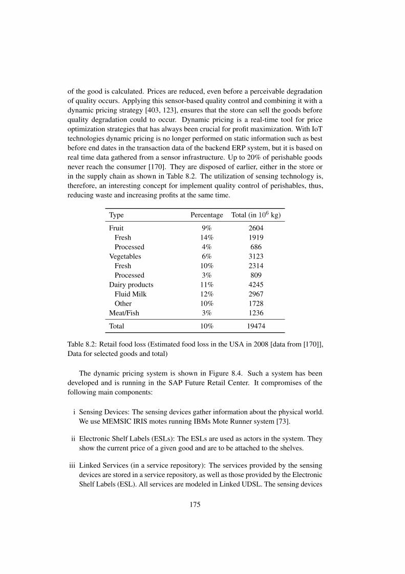
of the good is calculated. Prices are reduced, even before a perceivable degradationof quality occurs. Applying this sensor-based quality control and combining it with adynamic pricing strategy [403, 123], ensures that the store can sell the goods beforequality degradation could to occur. Dynamic pricing is a real-time tool for priceoptimization strategies that has always been crucial for profit maximization. With IoTtechnologies dynamic pricing is no longer performed on static information such as bestbefore end dates in the transaction data of the backend ERP system, but it is based onreal time data gathered from a sensor infrastructure. Up to 20% of perishable goodsnever reach the consumer [170]. They are disposed of earlier, either in the store orin the supply chain as shown in Table 8.2. The utilization of sensing technology is,therefore, an interesting concept for implement quality control of perishables, thus,reducing waste and increasing profits at the same time.
Type Percentage Total (in 106 kg)
Fruit 9% 2604Fresh 14% 1919Processed 4% 686
Vegetables 6% 3123Fresh 10% 2314Processed 3% 809
Dairy products 11% 4245Fluid Milk 12% 2967Other 10% 1728
Meat/Fish 3% 1236
Total 10% 19474
Table 8.2: Retail food loss (Estimated food loss in the USA in 2008 [data from [170]],Data for selected goods and total)
The dynamic pricing system is shown in Figure 8.4. Such a system has beendeveloped and is running in the SAP Future Retail Center. It compromises of thefollowing main components:
i Sensing Devices: The sensing devices gather information about the physical world.We use MEMSIC IRIS motes running IBMs Mote Runner system [73].
ii Electronic Shelf Labels (ESLs): The ESLs are used as actors in the system. Theyshow the current price of a given good and are to be attached to the shelves.
iii Linked Services (in a service repository): The services provided by the sensingdevices are stored in a service repository, as well as those provided by the ElectronicShelf Labels (ESL). All services are modeled in Linked UDSL. The sensing devices
175

Service Resolution Infrastructure
Business Process Execution Engine
R ˆ
SAP Retail Bridge
R ˇ
Services Associations
SAP GUI
ERP
REST Interface
Mote Sensor PRA
SAP System
ESL Actuator PRA
R ˇ
IrisMote Bounce WebServive
R ˇ R ˇ
ESL
R ˇ
Integration Platform
R ˒
Figure 8.4: Technical Realization of a Dynamic Pricing business process
have a CoAP endpoint, while the ESLs use an HTTP REST interface at applicationlevel.
iv Service Resolution Infrastructure: We are using a resolution infrastructure [165] fordiscovery services. The resolution infrastructure contains the associations betweensensing devices, actors and the corresponding service information. It also offerslocation-based and semantic service discovery functionalities.
v Integration Platform: An prototype integration platform, based on SAP RWIP[242] for communication with SAP systems enhanced with the ability to producesemantics-aware Linked USDL based services (see Chapter 4.6 and Chapter 5),is used in in order to make the wireless sensor nodes and the ESLs accessible. InFigure 8.4 only the essential parts of the prototype are shown.
vi Business Process: The adaption of the retail price, as shown by the ESLs, ismanaged by an IoT-aware business process [267]. A prototype IoT-aware BPMNmodeler was used. It measures the environmental parameters and adjusts the price asneeded. The process model contains declarative descriptions of the particular goodfor which it can be executed, as well as the IoT-related operations (sensing or acting).The execution engine then generates a SPARQL query based on these descriptionsand queries the resolution infrastructure for the corresponding IoT services. Uponthe execution of the process, the engine accesses the service endpoints. In addition,the execution engine writes the environmental parameters and the prices into theSAP retail system.
176

8.3.2 Ranked Requirements
The requirements have already been detailed out in Chapter 4.6.1. We briefly repeat therequirements and rank them starting with the most important first. As noted in Chapter8.2.4 and recommended by Bass et al. [30] we will limit ourselves to the five mostimportant requirements.
#R1 Linked Services: The architecture should be able to use linked services as intro-duced in Chapter 4.4. It should be able to follow links and download servicedescriptions.
#R2 Constrained Resources: The architecture must be able to deal with devices thatare constrained in terms of memory, computation and communication.
#R3 Reconfigurability and Reprogrammability: Changing requirements and costpressure will lead to the need of a constant reconfiguration and shared use ofresources. Therefore, it is essential that the devices can be reconfigured andreprogrammed easily.
#R4 Service Discovery: The ERP system should be able to discover services providedby the constrained devices.
#R5 Standard Technologies: Use of standard technologies for direct access of IoTdevices
8.3.3 Scenarios
In the following we present eight scenarios that were derived from the business driversin conjunction with the ranked requirements. Five scenarios consider typical use-cases,two are growth scenarios and one exploratory scenario. We use the integration platformas described in Chapter 4 combined with experiences from the business use case, andprototype described in Chapter 8.3.1 as subject under evaluation.
8.3.3.1 Scenario 1
Scenario # 1 is a use-case that addresses Linked Services (R#1), constrained resources(R#2) and service discovery (R#4)
Description
The container is arriving at different harbors or at the retailer as described in the businessscenario. Linked Service descriptions need to be exchanged, they are stored on themote. The ERP system later on wants to utilize the semantic data stored on the smartdevice for reasoning.
177
Architectural Mapping
On the mote there is a technical endpoint, that runs, for example, CoAP. The servicedescription is stored on-device and can be retrieved upon arrival at the harbor. On theintegration platform an agent for the Mote Runner system is running an adapter forthe MRv6 protocol. Later on, this allows, direct access to the motes. The discoveryagent, in cooperation with the Mote Runner adapter, detects a new mote and adds itto the list of newly detected motes. It is now monitored by the lifecycle controller.The integration platform now downloads its service description. The enterprise systemstores the service description in a service repository. From that point on, its available tothe industry-specific reasoning engines within the enterprise system.
Conclusions
Based on the architectural mapping the scenario can be fulfilled by the proposedarchitecture. The major risks discovered are not of architectural nature, but come fromstandardization. The interface for accessing the service description needs to be eitherstandardized, or at least, known to all adapters.
8.3.3.2 Scenario 2
Scenario #2 is a use-case that addresses Linked Services (R#1) and constrained re-sources (R#2).
Description
In this scenario we assume a very constrained device. We assume that it has somememory to describe its basic services, but not even have enough memory available tostore all related service information. It still needs to be able to attach to the enterprisesystem. A service level agreement and further sensor-specific information is stored onthe repository of the shipping company that owns the container.
Architectural Mapping
The scenario can be implemented by the architecture. This scenario shows how linkeddata principles can be used to obtain further information about almost anything, includ-ing hardware specification. The basic service description is processed as in scenario#1. The main difference is that the service now can be completed by the service de-scription agent and the resolve RDF agent. It is assumed that an Internet connection isavailable. The Linked Services approach allows using a domain-specific ontology todescribe service characteristics. For example, the hardware specifications of the sensorsinvolved (luminance, humidity, and temperature) could be described via an ontologyand downloaded from the manufacturers homepage, following the links in the originalservice description. The data can be loaded on-demand. For example, when the service
178

description agent tries to retrieve the service level agreement, instead of getting thedata delivered by the mote, it gets a redirection. It follows the links in this redirectionuntil it has all the data it needs. The data could be stored in an enterprise system of theshipping company. The respective service is stored in a service repository and madeavailable to its partners in the enterprise network.
The description of a basic service also allows using the mote in situations, where noInternet connection is available. In that case, the mote could still be used for monitoringtasks and be synchronized only at harbors.
Conclusions
The scenario can be fulfilled. The challenges and risks concerning linking differentsources together are more an a management and standardization level than on a technicallevel: all involved parties need to agree on some ontologies in order to be able to linkservices. Availability and correctness needs to be guaranteed, as well.
8.3.3.3 Scenario 3
Scenario # 3 is a use-case that addresses reconfigurability and reprogrammability (R#3)
Description
A container should get a new configuration. It has to be reconfigured by replacing thetechnical service on the mote and its service description. Both are stored on the moteand should be replaced on-the-fly.
Architectural Mapping
The enterprise system needs to instruct the integration platform to reflash the device.The lifecycle-controller ensures that the device is marked as invalid for the time beingand it is currently reconfigured and reprogrammed. The physical resource adapter ofthe system communicates with the service management unit of the device to store newdata. This can be either done before or after the actual reflashing of the software onthe device. It is highly hardware-specific. For the integration platform to perform thisoperation a (vendor-specific) PRA is necessary, or alternatively some standard has to beestablished. After the reflashing of the device it is reattached to the integration platform.Its service description is downloaded and integrated into the system.
Conclusions
This scenario can be generally fulfilled by the architecture. Some technical precondi-tions have to be fulfilled: The mote must be able to receive a new service description,and store it on the mote. Before or after that it also must be able to be ”reflashed”,preferably with minimal to no human interaction.
179
8.3.3.4 Scenario 4
Scenario # 4 is a growth-scenario. It addresses Linked Services (R#1) and constrainedresources (R#2), and service discovery (R#4).
Description
A new device technology should be incorporated into the system. It uses a proprietaryprotocol to attach and reattach to the network and for transportation. The communicationat the application-layer is done via a standardized protocol.
Architectural Mapping
The first step is that a new physical resource adapter for this particular device/protocolcombination has to be written. The device would need to support reconfiguarabilityand reprogrammability on the device to support R#4. Otherwise, it is not possible tosupport that requirement. In addition, access to the network needs to be achieved byproviding software drivers for the IPI. The actual communication with the device canthen happen via a standardized technology.
Conclusions
This scenario can be generally fulfilled by the architecture. It depends on the actualcharacteristics of the hardware, if and how many of the requirements can actually befulfilled. This is not a limitation of the architecture though. In order to improve inter-operability of different hardware devices, it would be necessary to further standardizethose aspects.
8.3.3.5 Scenario 5
Scenario # 5 is a growth-scenario that addresses Linked Services (R#1), constrainedresources (R#2), and service discovery (R#4).
Description
The growth-scenario is shares some similarities with Scenario #4. A new devicetechnology should be incorporated into the system. It uses a proprietary protocolto attach and reattach to the network as well as for transportation. The protocol isproprietary and it is not possible that an ERP (or the Internet in general) at any pointcan directly connect to it. Nonetheless, the ERP should be provided with a service via astandardized technical interface.
180

Architectural Mapping
The first step is that a new physical resource adapter for this particular device/protocolcombination has to be written. The device would need to support reconfiguarabilty andreprogrammability on the device to support R#4. Otherwise, it is not possible to supportthat requirement. In addition, access to the network needs to be achieved by providingsoftware drivers at least for the adapter. To allow access from the ERP or the Internet ingeneral a proxy solution needs to be written. The integration platform could create asimple proxy, accessible through standard web technologies like HTTP or CoAP. Theactual technical interface on the device is then called by the physical resource adapter.
Conclusions
The architecture could support this scenario as well, with minimal changes. Onepossible way would be to generate a proxy out of a given service description. Theservice description would have to specify the technical interface towards the ERP. Thedevice needs to provide a means to access the actual functionality. Next, automaticproxy generation could be applied. As long as the device access can be mapped toa RESTful protocol this could be done automatically. If the protocol itself is alsoproprietary handwritten glue code might be necessary. The ERP would then access thetechnical interface on the IPI and not on the device directly.
8.3.3.6 Scenario 6
Scenario # 6 is a use-case that addresses Linked Services (R#1) and constrainedresources (R#2).
Description
The dynamic pricing scenario include ESLs (Electronic Shelf Labels) as third-partyactuators. The architecture should be able to include actuators.
Architectural Mapping
Out of scope of the architecture is currently real-time support. The actuators needto be accessible via standard Internet technologies. This currently comes with somelimitations: delay, jitter and packet loss needs to be considered, as well as driftingunsynchronized clocks. A scenario like the described electronic shelf label can beintegrated easily, because its updates rates are typically not time-critical.
Conclusions
The architecture supports this behavior. Real-time support with immediate response iscurrently out of scope of the architecture. It can support soft realtime and firm realtime,but hard realtime cannot be achieved without architectural modifications.
181

8.3.3.7 Scenario 7
Scenario # 7 is a use-case that addresses Linked Services (R#1), constrained resources(R#2) and modeling of service characteristics (R#5).
Description
We are assuming a very constrained device. The device is not able to store even a smallservice description. It can hold some data though.
Architectural Mapping
Even, if no service description is stored on the mote the architecture can still accom-modate this situation. The minimal requirement is that there is a endpoint available;running software that can at least return one redirection. This redirection links to anexternal resource – for example, on an enterprise system of the container shippingcompany. The enterprise system can connect to the device through an adapter. Now, theservice description can be processed as if it were available directly on the sensor mote.This scenario requires the availability of an Internet connection. In rural scenarios oron a ship without a working Internet connection, it would not be possible to connect tothe device.
Conclusions
The use-case can be fulfilled. It has imitations though, when no Internet connection isavailable. As a general recommendation, all motes should provide at least a minimalservice description that allows to interconnect with the device. Nonetheless, for themotes to be self-descriptive in all scenarios, a minimal service description on the moteis necessary.
8.3.3.8 Scenario 8
Scenario # 8 is a exploratory-scenario.
Description
In future, it might well be that more and more computation (business process decom-position [158]) is happening on the device. As a result, the interactions between thedevices and the integration platform or the enterprise backend will increase.
Architectural Mapping
The problem of supporting this scenario does not directly involve the integrationplatform. Orchestration of the services needs to be done on the ERP side and it doesnot directly involve the integration platform. In future, additional semantic descriptions
182

might support such an orchestration engine and it might even allow automatic matchingof services.
Conclusions
Business process decomposition [158] support can be achieved by using the integrationplatform. Nonetheless, all the logic of orchestrating this additional logic needs to bedone in the ERP system.
8.3.4 Overall Assessment
We performed a scenario-based assessment of the proposed architecture. The archi-tectural mapping has shown that the proposed architecture in principle is capable offulfilling the defined requirements and their underlying business drivers. The use oflinked services and semantics are on an architectural level able to enable interoperabilityand scalability. Devices and information from different vendors can be incorporated.Some risks have been identified as well. Given the assumed technology stack (REST-based services, IP/6LoWPAN based, CoAP) it is pretty obvious that the architectureis currently targeting only soft-realtime systems. A move towards firm-realtime oreven hard-realtime seems basically possible, but most likely will require changes to thearchitecture and the protocol stack. Very constrained devices that lack self-descriptioncapabilities can be integrated as well. Nonetheless, in such scenarios an Internetconnection is mandatory.
8.4 Survey
We conducted a survey on semantics with an emphasis on the potential of semantics inenterprise IT systems. Semantics are currently being intensively researched by bothindustry and academia. Our objective was to identify the actual needs of IoT withregard to semantic support and to identify current shortcomings. We also investigatedreasons for the perceived ”semaphobia”. Lanthaler and Gutl [225] coined the termsemaphobia to describe the fear of an average developer to use semantic technologies.We first describe the methodology in Chapter 8.4.1, then the threats to its internal andexternal validity in Chapter 8.4.2, before we proceed to discuss the results of the surveyin Chapter 8.4.3.
8.4.1 Methodology
The survey was distributed among domain experts, from industry (among others: SAP,IBM, NEC, Orange, Telefonica) and academia. While some experts were recruiteddirectly, the majority of the respondents were self-selected. The survey was conductedonline, with anonymity being guaranteed and technically enforced by the system. Asthe IoT is a very broad field, we did not ask questions about mobile phone development,
183

and limited protocol related questions specifically to systems where an ISO/OSI-likestack [406] is used. The questionnaire was designed to be rather short, as we did notexpect professionals to spend more than five to ten minutes on it. To further speedup the process the survey mostly contained multiple-choice and ranking questionsand only very few free text entries. The survey included a control question: thequestion if semantics will play a significant role in future IoT was repeated. Incompletequestionnaires and those failing the sanity check were not taken into consideration.
Some questions ask for agreement or disagreement with statements about the IoT orsemantics. We chose a 4-point Likert [236] scale. The Likert-scale allows participantsto specify their level of agreement or disagreement, typically on an agree-disagree scale,for a number of different statements. In literature, especially in psychology, there isplenty of research on the optimal number of Likert items and the value of a neutralanswer. It is widely acknowledged that the number of ”negative” options, should equalthe number of ”positive” options. Furthermore, the number of people choosing a neutraloption decreases with the number of options given [253]. The optimal number ofanswer options depends on the subject of the survey. For example, to express feelings,having more options, closer to ten, seem to be more favorable [305]. When choosingto agree or disagree with statements, a lower number might be more suitable, as itotherwise remains unclear how different subjects perceive the difference between twochoices [81]. Therefore, we decided to use a four-point Likert scale without a neutraloption to force people to form an opinion, even if it is only a slight tendency towardsone or the other side. The scale is quite intuitive and should not leave the subjects muchroom for interpretation. They can agree or disagree, or they need to give a tendency inone or the other direction.
We asked the participants specifically to focus on constrained networks and wirelessprojects, and more specific on IEEE 802.15.4 and similar based protocols. We particu-larly asked not for mobile (phone) development, as for example an IPad-based shoppingassistant. The participants were asked to focus on communication with constraineddevices and the constrained devices themselves.
8.4.2 Threats to internal or external validity
As the study was conducted anonymously, it is not possible to validate that the claimsmade are valid. No incentives were given for participating. Most industrial participantsworked with IoT-systems in industrial automation, retail or logistics. The responses byparticipants from academia were (if a sector was chosen) mainly from automation andlogistics, and the broad areas of smart city. The survey was mainly distributed in anenvironment that is close to enterprise systems and enterprise resource planning, or tosemantic systems. Furthermore, most of the projects and the research in the surveyedcommunity are traditionally based on IEEE 802.15.4 and similar. As this was ourmain research focus and we were particularly interested in the needs and views of thisgroup. We did not survey other IoT-fields – for example mobile development basedupon IEEE 802.11. Therefore, some of the results might not be generalizable to other
184

problem domains or communities. Semantics is one of the major concerns in nowadaysenterprise systems and the participants of the survey are probably from a communitythat is more likely to use semantic technology and more verbose application-layerprotocols, than for example, a more ”bit-and-byte”-orientated community, such asthe automotive sector. Nonetheless, we assume the results to be generalizable to anyenterprise (ERP-) and semantics-prone community. For other communities, furtherresearch is suggested.
8.4.3 Results
In the following, we present and discuss the results of the survey. We categorize theresults into four groups: (i) general statistical information about the participants andtheir skillsets, (ii) protocols, (iii) semantics and (iv) enterprise integration.
8.4.3.1 Participants
The total number of participants was 178. Their experience levels, origin and skillsetsare detailed in Table 8.3. There were twice as many participants from industry as fromacademia. The majority of participants had at least three years of professional experi-ence and a more than basic understanding of IoT and semantics. Most participants hadat least some experience with semantics and IoT. Naturally, the expertise in enterprisesystems and enterprise interoperability was higher for industry participants.
8.4.3.2 Protocols
In the following we give an overview on our results with regard to the used protocolstack. We survey the currently used protocols on the network layer, transportationlayer and application-layer. We were mainly interested in the penetration of REST-based protocols and the progress of standardized protocols. In the past two decades,especially 802.15.4 networks were often associated with custom made, specialized andoften proprietary, protocols. Industry used a lot of vendor-specific, non standardizedprotocols. This started to change with initiatives such as ZigBee, 6LoWPAN and ageneral industry-wide trend towards more integration and standardization.
The views of the community with regard to the current IoT-protocols have beensurveyed with a 4-point Likert-style questionnaire. The Likert items and the responsesare illustrated in Figure 8.5. First, we asked if current application-layer protocols areconsidered sufficient for the special needs of IoT-applications. In total, there was asmall majority towards more work needs to be done on the application layer. A largemajority believes that network management protocols need more work to adopt themtowards IoT, suggesting the need for further research in this area. There seems to beconsensus that most future IoT-applications will be IP-based to some degree, and a biastowards REST-based architectures. In total 87% of the participants opted for a futureIP-based Internet of Things. Especially, the participants from industry (90%) expressed
185
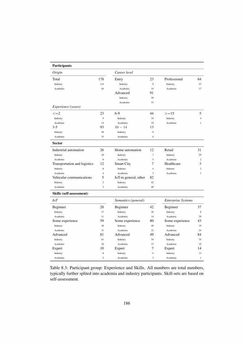
Participants
Origin Career level
Total 178 Entry 23 Professional 64Industry 114 Industry 9 Industry 47
Academia 64 Academia 14 Academia 17
Advanced 91Industry 58
Academia 33
Experience (years)
<=2 23 6-9 44 >=15 5Industry 9 Industry 34 Industry 4
Academia 14 Academia 10 Academia 1
3-5 93 10− 14 13Industry 58 Industry 9
Academia 35 Academia 4
Sector
Industrial automation 26 Home automation 12 Retail 31Industry 20 Industry 7 Industry 29
Academia 6 Academia 5 Academia 2
Transportation and logistics 12 Smart City 7 Healthcare 3Industry 8 Industry 4 Industry 2
Academia 4 Academia 3 Academia 1
Vehicular communications 5 IoT-in general, other 82Industry 2 Industry 42
Academia 3 Academia 40
Skills (self-assessment)
IoT Semantics (general) Enterprise Systems
Beginner 28 Beginner 42 Beginner 37Industry 17 Industry 28 Industry 8
Academia 11 Academia 14 Academia 29
Some experience 59 Some experience 80 Some experience 43Industry 28 Industry 48 Industry 19
Academia 31 Academia 32 Academia 24
Advanced 81 Advanced 49 Advanced 84Industry 61 Industry 34 Industry 74
Academia 20 Academia 15 Academia 10
Expert 10 Expert 7 Expert 14Industry 8 Industry 4 Industry 13
Academia 2 Academia 3 Academia 1
Table 8.3: Participant group: Experience and Skills. All numbers are total numbers,typically further splited into academia and industry participants. Skill-sets are based onself-assessment.
186

19%
10%
13%
81%
90%
87%
28%
25%
26%
72%
75%
74%
23%
19%
21%
77%
81%
79%
58%
75%
69%
42%
25%
31%
50%
71%
63%
50%
29%
37%
52%
61%
58%
48%
39%
42%
Future IoT−based applications will be IP based (e. g. 6LoWPAN)
Most future IoT applications will be REST−based
Energy consumption is a major issue in designing IoT protocols
Todays network management protocols are sufficient for IoT applications
IoT applications will continue to use a proprietary protocol stack
Todays application layer protocol are already sufficient with regards to the special needs of IoT−applications
AcademiaIndustry
Total
AcademiaIndustry
Total
AcademiaIndustry
Total
AcademiaIndustry
Total
AcademiaIndustry
Total
AcademiaIndustry
Total
100 50 0 50 100
Percentage
Response disagree slightly disagree slightly agree agree
Figure 8.5: Usage and potential of IoT-protocols (on a 4-point Likert scale)
the opinion that the IoT will be largely IP-based. This matches the results given inTable 8.4. We always asked for the protocols that are used at the moment, the plannedprotocols and the expected industrial use.
Curr Please select the protocols you are currently using in your project(s). Pleaseconsider only the protocols you are actually using for communication with yourIoT-device.
Planned Considering the near- to midterm future of your project(s) (3-5 years outlook).Please check the protocols that you would most likely use for any new projects,or advancements of your current projects. What protocols would you use rightnow if you would have to start a new project? Please consider only the protocolsyou are actually using for communication with your IoT-device
Expected Please select the project you think new projects will use or you generallyexpect the industry to use in future. What do you think the industry will/shouldchoose in general for future IoT-projects? In which direction do you think theindustry will move?
The planned usage and the further expected usage of standard protocols is veryhigh. The HTTP protocol family is the most frequently used in industry. CoAP,
187

as a second RESTful protocol, also attracted quite some attention. But this wasmainly in academia and not as much in industry. MQTT [177] was also mentionedby quite a few participants. Interestingly, the expected usage of CoAP and MQTT issignificantly higher than the planned. This could be due to the recent attention thatboth protocols have received. AMQP [390], an alternative to MQTT was mentionedonly very infrequently. WebSockets did not attract widespread use either. WebSocketshad to be manually entered by the participants though, so the numbers for the expecteduse are most likely not conclusive. However, what can be said is that WebSockets didnot make it into a generally accepted IoT concept – at least, not to a degree where ourparticipants would naturally have mentioned it ”as to be used” protocol. SOAP, whichis otherwise widely used in enterprises [132], does not seem to play a major role inthe IoT. Surprisingly, ZigBee is not that widely used either. Nonetheless, this could beexplained by the surveyed community. The OData protocol is not yet considered to bean ”IoT-protocol”.
On the network and the transport layers, the answers showed a trend towardsstandardization as well. The data indicates that two types of IoT-streams coexist at themoment: Developments based upon small very constrained devices with specializedprotocols and already quite some developments on platforms capable of running less-constrained protocols, such as IPv6 and TCP. This development is most likely drivenby the general need for standardization, in conjunction with advances in hardware, asignificant drop in hardware prices and the recent advent of many new platforms. Thenumbers show that most people expect standardization towards the high-level protocolsor their IoT adoptions (such as 6LoWPAN). This correlates well with the expectationsof our participants regarding REST-based and IP-based IoT-developments in future.
8.4.3.3 Semantics
Apart from the used protocols, we were mainly interested in the views and the generalattitude of the community with regard to semantic technologies and semantics ingeneral. Semantic technologies and semantics have been around for some time now,but they have not yet gained the widespread use that was once predicted. We asked ourpartiticpants what are, in their opinion, the main obstacles hindering the widespreadadoption of semantics in the Internet of Things. The participants were given a list of sixtypical reasons that might be an obstacle for the wide-spread use of semantics. Theywere asked to rank these reasons from the most influential reason to the least influential.
In Figure 8.6(a) we show the main obstacle – that is, the one the participantsranked first. The most frequently mentioned issues were knowledge / awareness ofdevelopment staff and standardization, followed by development tool support. Thedifferences between the responses of industry participants and academic participantswere small. Only the infrastructure seems to be viewed more critically by academiathan by industrial participants. Figure 8.6(b) shows the same numbers in weighted andnormalized ways. As mentioned earlier, the participants were asked to rank the sixpossible obstacles from most important to least important. We multiplied all ”most
188

Network layer Curr Plan Exp Transport layer Curr Plan Exp
IPv4 16.29% 7.86% 6.17% UDP 25.84% 25.28% 51.66%Industry 21.92% 11.40% 7.89% Industry 34.21% 34.21% 56.14%Academia 6.25% 1.56% 3.12% Academia 10.93% 9.37% 43.75%
IPv6 29.21% 56.17% 85.39% Reliable UDP (nonCoAP)
6.74% 6.17% 20.24%
Industry 35.08% 64.91% 86.84% Industry 5.26% 3.50% 14.03%Academia 18.75% 40.62% 82.81% Academia 9.37% 10.93% 31.25%
6LoWPAN 45.50% 80.33% 97.75% Reliable UDP(CoAP)
23.59% 36.51% 68.53%
Industry 49.12% 80.70% 98.24% Industry 20.17% 36.84% 67.54%Academia 39.06% 70.31% 92.18% Academia 29.68% 35.93% 70.31%
Custom 802.15.4protocol
49.43% 33.14% 20.22% TCP 47.19% 60.11% 76.40%
Industry 38.59% 19.29% 10.52% Industry 60.25% 77.19% 78.94%Academia 68.75% 57.81% 37.50% Academia 23.43% 29.68% 71.87%
Custom (other) 21.91% 23.03% 10.11% Custom/other(TCP-like)
36.51% 29.77% 18.53%
Industry 19.29% 21.05% 7.89% Industry 30.70% 21.92% 12.28%Academia 26.56% 26.56% 14.06% Academia 46.87% 43.75% 29.68%
Zigbee 8.98% 9.55% 51.68% Custom/other 42.13% 39.32% 16.29%Industry 10.52% 10.52% 53.50% Industry 33.32% 29.82% 10.52%Academia 6.25% 7.81% 48.43% Academia 57.81% 56.25% 26.56%
Application Layer Curr Plan Exp Curr Plan Exp
CoAP 23.59% 40.44% 62.92% AMQP 1.12% 1.12% 1.12%Industry 12.28% 32.45% 59.64% Industry 0.87% 0.87% 0.87%Academia 43.75% 54.68% 68.75% Academia 1.56% 1.56% 1.56%
HTTP(S) 54.94% 55.06% 76.40% KNX 6.17% 5.61% 11.79%Industry 63.15% 65.78% 75.43% Industry 7.89% 7.01% 9.64%Academia 39.04% 35.93% 78.12% Academia 3.12% 3.12% 15.62%
SOAP 12.35% 8.42% 16.85% MODBUS 7.86% 8.42% 7.86%Industry 18.42% 12.28% 20.17% Industry 10.52% 10.52% 7.89%Academia 1.56% 1.56% 10.93% Academia 3.12% 4.68% 7.81%
ODATA 2.80% 3.93% 5.05% MQTT 20.78% 23.03% 49.43%Industry 3.50% 5.26% 6.14% Industry 28.94% 32.08% 57.01%Academia 1.56% 3.12% 3.12% Academia 6.25% 6.25% 35.93%
CAN 6.17% 6.17% 5.06% WebSockets 2.24% 2.24% 1.68%Industry 7.89% 7.89% 6.14% Industry 2.63% 2.63% 1.75%Academia 3.12% 3.12% 3.12% Academia 1.56% 1.56% 1.56%
Other/Custom 29.77% 29.21% 29.77% Zigbee 13.48% 13.48% 38.20%Industry 20.17% 15.78% 23.68% Industry 15.78% 16.66% 47.36%Academia 46.87% 51.56% 40.62% Academia 9.375% 7.81% 21.87%
None 4.49% 4.49% 1.12%Industry 0.00% 0.00% 0.00%Academia 12.50% 12.50% 3.13%
Table 8.4: Used Protocols, in percentage of the participants (in total, and per group)choosing the respective protocol. Participants could choose more than one protocol.The responses are categorized into current usage (curr), planned knowledge (plan) andthe anticipated or expected use of the industry in future (exp)
189

0
10
20
30
40
50
60
Per
cen
t
Total
Industry
Academia
0
0,2
0,4
0,6
0,8
1
1,2
Wei
gete
d (
nro
mal
ized
)
Total
Industry
Academia
(a) Main (percentage)
0
0,2
0,4
0,6
0,8
1
1,2Total
Industry
Academia
(b) All (weighted, normalized)
Figure 8.6: The main obstacles for not using semantic technologies (”semaphobia”).Participants had to rank the reasons from most important to least important. Results inpercent of main reason (top ranked) and all reasons weighted by importance
important” entries with six, the second most important with five and so on. Here,it becomes even more evident that education of developers and standardization isconsidered the main obstacle for the use of semantic technologies. Tools support, forboth domain experts and developers did not rank very high. Academia consideredtool support for domain experts irrelevant, while industrial participants gave it onlya minor importance. We found this quite surprising as semantic tool support forbusiness specialists is still considered a weak spot in the business modeling community[47, 169, 55]. Nonetheless, the participants’ views might be due to the fact that systemdesigners are not yet fully convinced of semantic technologies, and therefore theimportance of business users is not yet particularly high and therefore not visible yet.
The attitude of the community towards semantics, and more explicitly semantics inthe IoT was surveyed with a four point Likert-style questionnaire. The individual Likertitems and the distribution of the answers are shown in Figure 8.7. Most participantsagree that semantics will play a role in future IoT systems. Some think that it is toobloated/an academic toy, or as one of the participants stated in a personal mail to usthat it is ”a hype from bored academics that no one will remember in a few years”
Next, we proceeded to ask the participants about the actual usage, opportunitiesand main advantages of using semantic technologies. We presented the participantswith a list of seven opportunities of semantics in the Internet of Things as identified byus. The seven opportunities are:
Self-healing If an overall system is able to detect the situation that individual parts ofit do not work as intended and automatically takes measures to either repair orreplace these parts, the system is said to be self-healing [186]
190
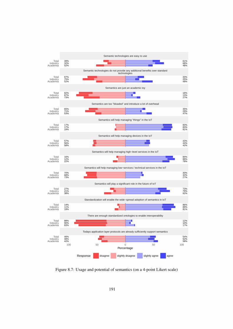
52%32%39%
48%68%61%
52%75%67%
48%25%33%
73%87%82%
27%13%18%
53%71%65%
47%29%35%
19%17%17%
81%83%83%
58%56%57%
42%44%43%
22%12%16%
78%88%84%
73%68%70%
27%32%30%
38%21%27%
62%79%73%
19%11%14%
81%89%86%
83%90%88%
17%10%12%
42%48%46%
58%52%54%
Semantic technologies are easy to use
Semantic technologies do not provide any additional benefits over standardtechnologies
Semantics are just an academic toy
Semantics are too "bloaded" and introduce a lot of overhead
Semantics will help managing "things" in the IoT
Semantics will help managing devices in the IoT
Semantics will help managing high−level services in the IoT
Semantics will help managing low−services / technical services in the IoT
Semantics will play a significant role in the future of IoT
Standardization will enable the wide−spread adoption of semantics in IoT
There are enough standardized ontologies to enable interoperability
Todays application layer protocols are already sufficiently support semantics
AcademiaIndustry
Total
AcademiaIndustry
Total
AcademiaIndustry
Total
AcademiaIndustry
Total
AcademiaIndustry
Total
AcademiaIndustry
Total
AcademiaIndustry
Total
AcademiaIndustry
Total
AcademiaIndustry
Total
AcademiaIndustry
Total
AcademiaIndustry
Total
AcademiaIndustry
Total
100 50 0 50 100Percentage
Response disagree slightly disagree slightly agree agree
Figure 8.7: Usage and potential of semantics (on a 4-point Likert scale)
191

Self-configuring A self-configuring system can be described as having the propertythat it does not require manual configuration before it is ready to be used. Inother words, a self-configuring system automatically adapts to its environmentand to the needs of the user. [186]
Reasoning/Sense Making Reasoning enables backend systems to automatically per-form reasoning on data coming from various sources. Semantic annotations canto be understood and processed by enterprise IT systems.
Device Management Device Management is concerned with information about theused devices and their capabilities.
Management of Things Things, or entities, are the subjects of the Internet of Things.This can be any physical object of interest to a system. Semantics make propertiesof and connections between things explicit.
Interoperability at technical level Interoperability at a technical level is concernedwith the description of the technical interface of services, e.g. what calls can bemade to a technical endpoint, how the resources look like.
High-level interoperability Interoperability is not restricted to the technical layer only.Interoperability at a semantic level allows systems to not only know that thereceived value is a float, but that it is a float representing a temperature with agiven precision and that it is monitoring a specified good.
The participants were given the same short definitions. They were asked wherethey see the most opportunities for semantics to make an impact on IoT. They couldchoose from a range of none to any. The results are presented in Figure 8.8. The mainadvantages of semantics are seen in high-level interoperability and reasoning, followedby the management of things. Interoperability at an endpoint level, a topic that is alsoaddressed by our integration platform, is not yet seen as an area where semantics cancontribute a lot. The differences between academia and industry were negligible.
Given that most people think there is potential in semantics, it is interesting to seeits actual usage: We summarized the results in Table 8.5. Participants could choosefrom a list of widely-recognized uses of semantics and select what they are using it fortoday, if they do. They were asked to express what their short- to midterm plans areand what they think the industry will move towards. In this case, the question was notwhere they see most benefit or most opportunities, but to which degree they are usingthe technology and what they think will happen.
Reasoning seems to be one of the most important topics discussed currently. Giventhat research on protocols and energy efficiency has been conducted for more thantwo decades now it is, in our opinion, just the logical consequence that IoT-researchmoves one layer or two layers up and is spending more resources on application topics.Considering the huge interest in reasoning, it could also be the main driver behinddescribing things, services and devices.
192

0
20
40
60
80
100
%
Total
Industry
Academia
Figure 8.8: Attitude towards opportunities/usages of semantics in IoT (in percentage ofparticipants per item, multiple selections were possible)
This part of the survey was followed by a question that asked for any specificIoT-related ontology people could think. There were some mentions of enterpriseinternal ontologies. The only ontology that was mentioned more often was SSN.
8.4.3.4 Enterprise Integration
We were also interested in enterprise or, more generally, ”outer world” integration. TheInternet of Things vision, to some degree, assumes direct use- and addressable smartobjects. We call that direct access, which means with only transparent network devices,if any. A network device is called transparent, if other devices on a network do not needto be aware of its existence. On the other side of the spectrum are gateway solutions,where communication is done via some intermediary that also offers the services. Insuch a setup, for example sensors, do not appear directly and they are not directlyaddressable or known to the service consumer. We call this a gateway access. A typicalexample for a gateway solution is some enterprise monitoring tool, where the sensorsare connected through a specialized protocol to the gateway. On the gateway the date iscollected and the gateway is the interface towards the outer world. Also, many homeautomation systems follow the same principle. The participants had to choose if their(main-) product/prototypes fall into or are closer to the first or second scenario. Intotal, direct access is used more often than a gateway solution (57.86% vs. 42.13% ofall participants). Industry participants choose direct access (64.9%) more often thanparticipants from academia, while academia had a slight bias towards gateway (56.2%).
193

Usage
Curr Plan Exp
Description of Things 28% 46% 82%Industry 32% 51% 86%
Academia 22% 37% 73%
Description of high level(semantic) services
14% 33% 73%
Industry 15% 43% 76%
Academia 11% 14% 68%
Description of low level(technical) services
6% 14% 28%
Industry 4% 9% 25%
Academia 8% 20% 34%
Description of Devices 11% 28% 61%Industry 11% 29% 69%
Academia 11% 23% 48%
Reasoning 38% 69% 88%Industry 42% 77% 91%
Academia 29% 46% 82%
Configuration 3% 5% 25%Industry 3% 4% 24%
Academia 5% 6% 26%
Table 8.5: Usage of semantic technologies for the mentioned reason (in total, and pergroup) in percent. Participants could choose more than one reason. The responses arecategorized into current usage ( curr), planned knowledge (plan) and the anticipated orexpected use of the industry in future (exp)
Direct Access seems to be more common now, than gateway solutions. In this question,the participants were forced into one option and should think about their current mainproject. Nonetheless, in our opinion both options are valid in the Internet of Things.A sensor node that is accessible via HTTP over a more powerful gateway is in ourbelief not necessarily worse than using direct access. Gateway solutions help reducingthe total energy consumption by applying specialized protocols and many solutionsworking or doing research with such specialized protocols might still choose a gatewayapproach.
We were also interested in how the IoT-devices are configured, for example if theycan automatically connect to a network without any manual work, or if the end user hasto configure the device or if some kind of administrator has to configure the devicesfirst. We differentiated the following four scenarios:
Fully-automatic: The configuration of the IoT devices is automatic, after an optionalinitial setup or one-time network configuration. Devices can potentially be addedand removed with further configuration steps.
End-user: The end-user is responsible for the configuration of the device – for example
194

by entering connection data.
Administrator, on-site: A technically skilled administrator has to be on-site to addand remove devices and to execute some configuration steps that go beyond whatan (less experienced) end-user can do.
Administrator, semi-automatic: A technically skilled administrator has to executesome configuration steps on a regular basis that go beyond what an (less experi-enced) end-user can do.
Fully-automatic and semi-automatic configurations are used most often. On-siteconfiguration, where a technically skilled administrator has to work on-site, is alsocommon in industry to some degree. There is a huge gap between academia and industryin manual end-user configurations. It is widely used by academic participants and onlyseldom by industrial participants. It seems likely that the end-user, in many cases, isthe research team itself.
0
10
20
30
40
50
60
70
80
Fully automatic End userresponsible
Administrator on-site
Administrator,semi-automatic
Total
Industry
Academia
Figure 8.9: Internet of Things - Configuration (in total, and per group) in percent ofall participants selecting this option. Participants could choose no, or more than oneoption.
Finally, we asked two questions regarding data gathering, data aggregation anddata processing for monitoring tasks. Participants could choose to answer one orboth questions, or to skip the questions. First, we asked where the processing ofthe monitoring data or the data aggregation takes place. We offered three differentpossibilities: on the device, on the gateway or in a backend-system. Second, we askedwhere the view of the system materializes and how it is gathered. The options were:device level (autonomous), centralized (event-based or time-based push), centralized(poll), or centralized (stream). The results are summarized in Table 8.6. Data processingand aggregation is mainly happening on a backend-system or on a gateway. Typically,
195

it seems that devices push information to the monitoring application in either an event-based or a time-based way. Stream processing is not yet widely used.
Processing of tasks / data aggre-gation
% Overall control and view on applica-tion
%
device level 11.79% device level (autonomous) 15.16%on a gateway 26.40% centralized, push, time-interval 14.04%on a backend-system 34.26% centralized, push, event-based 25.28%
centralized, poll 11.79%centralized, real-time stream 8.98%
Table 8.6: Data processing and overall system (application) view (non mandatoryquestion), answers in percentage of all participants choosing this option
8.4.4 Conclusions
We conducted a survey among domain experts from industry and academia. On onehand, to get an overview of the state of semantics, the Internet of Things and its relationto enterprises. On the other hand, the survey served as an input to our evaluation ofLinked USDL for IoT. First, we surveyed the general feeling about Internet of Thingsand Semantics. It seems to be widely anticipated that the (future) Internet of Thingswill be largely REST-based and IP-based. This might not be surprising at a first glance.Nonetheless, abstracting from the buzzword IoT and taking the history of the wirelesssensor networks into account, this was not a compulsory development, especially in anenterprise environment. First, because a considerable part of nowadays IoT communitydeveloped out of the sensor and actor community, as well as automation. In the past,both communities were to a considerable extend grounded in (sometimes proprietary)protocols that were neither IP-based nor REST-based, but still many solutions havebeen advertised as being part of the IoT. The IP or Internet part in such solutions, ifat all, was often not more than a gateway that provided some services. The servicesthemselves were technically realized through specialized protocols between the gatewayand some constrained devices. Second, also the enterprise community, which has onlyvery recently moved towards REST-based protocols. In the past, many enterprisecompanies based their products on either SOAP-services or proprietary protocols, suchas RFC and BAPI. Specialized protocols still have its share in the current IoT, butmost of our participants are already using standardized technologies or plan to movetowards standardized technologies, so a convergence towards REST-based and IP-basedprotocols can be expected. It is interesting that Enterprises move towards IoT-protocols,instead of moving enterprise protocols (as SOAP) towards IoT. CoAP, to some degree,seems to be in a special position. It was used by many participants from academia, butnot by many from industry. Nonetheless, many industry participants nonetheless statedthat they will consider it for future projects. In our opinion, it remains open whether
196

the protocol really will get a considerable industrial usage, or if the expected usage ismainly based on the recent hype the protocol has received in the IoT community. Thesurveyed community was split (see Figure 8.5) when asked if todays application-layerprotocols sufficiently address the special needs of IoT. The used protocols might changein future, with increasing hardware capabilities: The use of standard Internet protocols,suggests that more capable hardware is used now, something that was not alwaysassumed as given in the past. This might further influence the protocol stack towardsthe use of4 existing and mature technologies, or the new upcoming developments in theInternet such as HTTP/2 [40] or SPDY [116]. Even SOAP might experience a revivalthen. Applications could also use a more powerful node as application gateway thatuses a specialized protocol for communication with sensor nodes and a standardizedprotocol for communication with the outer world. It seems that the aspect of directcommunication with devices, as predicted by the IoT vision, is becoming increasinglycommon. Significantly less participants were using a gateway approach than the numberdirect communication. Combined with the expected IP-protocol use, this number canbe expected to grow in the upcoming years.
The overall picture with regards to semantics is even more diverse. The generalapplicability and reasonability of semantics seems not to be denied. Nonetheless, theuse of semantics is still not that high, a phenonemon coined ”semaphobia”. The maincurrent and expected usage of semantic information seems to be for reasoning and forincreasing interoperability. This is not surprising as sensor data is predestined for basingbusiness decisions on them. As the semantic technology has not been surveyed, it isunclear if there is an end-to-end semantic scenario or if the sensor data is transformedinto some semantic representation to be able to do reasoning. Description of Thingsranked second in usage, most likely this is due to its usage in reasoning applications.Still, the reluctance to use semantic technologies in general was also observed byus. Quite some participants agree to the statement that semantic technologies do notprovide additional benefits over standard technologies. Reasoning, for example, doesnot necessarily need to use RDF or other (standard) semantic (web-) technologies. Thetop reason for ”semaphobia”, is seen in a lack of training and awareness, followed by alack of standardization in terms of vocabularies and ontologies. Standardization of theactual semantic technologies or support from tools and infrastructure (e.g. triple-stores)did not rank high. We assume that with the next generation of computer scientist joiningthe industry the acceptance of semantics will raise, as many of those will already havehad contact with machine-learning, reasoning and semantics during their studies.
8.5 Linked USDL for IoT
In the following section, we will evaluate Linked USDL for IoT and several otherdescription languages with regard to nine selected evaluation criteria.
197

8.5.1 Introduction
We present a qualitative evaluation comparing Linked USDL for IoT with more tradi-tional technologies like WSDL, and competing semantic approaches like SA-WSDLand OWL-S. A brief introduction into those technologies and related concepts can befound in Chapter 2. First, we briefly introduce the used methodology and present thenine evaluation criteria that we use to evaluate the different service description lan-guages. We then evaluate the semantic and non-semantic service description languages,including Linked USDL for IoT, with regard to this evaluation criteria. Finally, wepresent the conclusions that can be deduced from our evaluation.
8.5.2 Methodology
We perform a criteria-based evaluation based upon an internal requirements-gatheringprocess, the IoT-A stakeholder workshops and our survey (unified evaluation criteria).The applied evaluation process is shown in Figure 8.1. The internal requirements andthe results of the IoT-A stakeholder workshops influenced the survey and they werealso used in the unified evaluation criteria. Based on the requirements mining process,as described in detail in Chapter 8.1, we distilled the following nine properties that aservice description has to fulfill and six characteristics that a corresponding IoT-systemshould have. First, we introduce the nine service description related characteristics:
Endpoint agnostic: Endpoint agnostic means that the service description should be asindependent of any specific technical endpoint technology as possible. The differ-ent technical endpoints in a sensing enterprise are typically heterogeneous. Thereexist proprietary protocols, like RFC or BAPI, webservices (SOAP), semanticweb-enabled interfaces (often RDF-based), as well as specialized protocols likeCoAP to mention only a few. Endpoint refers to any of those technical real-izations of a service. Any service description language that is chosen needs tosupport such formats and to describe them in a semantically interoperable way.
Support of Business Aspects: A service description needs to provide more informa-tion than just the mere technical details on how to call a technical interface.Therefore the selected service description language should be able to expressbusiness aspects like Service Level Agreements (SLAs) or pricing.
Distributed Descriptions: Nowadays, services can be composed of parts from dif-ferent vendors. We foresee the need of storing parts of a composed servicedescription at different locations. For example, the Quality of Information param-eters of a specific sensor node can be stored on the ERP of the sensors’ vendor.The service description should be able to capture such dependencies.
Self-Description capabilities: Service descriptions should be able to allow smartitems to describe themselves. The service description should ideally be stored onthe smart item itself.
198

Quality of Information: In sensing environments is the capability of describing qual-ity of information (QoI) parameters particularly important . Sensors often havea limited sensing range or work different in special conditions. The servicedescription should be able to express such QoI parameters.
Semantic Extensions possible: To enable reasoning and interoperability on a seman-tic level the service description needs should be customizable/extendable forspecific domains.
Infrastructure support: Infrastructure and tool support is essential in an enterpriseenvironment. A service description, which does only exist in paper, but withouttooling support for using it as part of a programming language or store it inappropriate repositories is not sufficient for professional use.
Standardization: Standardization of one of the key drivers of interoperability. There-fore, we evaluated the service description languages also towards standardizationor standardization efforts.
Discovery of further information / knowledge base: A service description can beused as a base to find further information from a knowledge base, for exampleabout the sensed entity.
We compared the Linked USDL approach first with other service descriptionlanguages, both semantic and non-semantic. We compared Linked USDL for IoT withWS-*, hRESTS, WADL, OWL-S and SEREDASj. The WS-* family was selectedbecause of its widespread use. OWL-S is represents a semantics-based language mainlyusing WSDL. SEREDASj represents a recent approach based on JSON-LD.
We carefully examined each service description language. To control an examinersbias we used the survey to determine the importance of these properties for possibleusers of a service description language. The results of our evaluation are presented inthe next section.
8.5.3 Evaluation
In the following, we present the results of our evaluation. As described in the previoussection we identified nine properties related to service description languages. Weused these properties as evaluation criteria. First, we present a grading of the nineevaluation criteria to show their perceived importance. Next, we perform a criteria-based evaluation. Finally, we combine the findings of the grading and the criteria-basedevaluation into a multi-variant comparison.
8.5.3.1 Evaluation Criteria Grading
As part of our survey, the participants where asked to grade each item by their perceivedimportance, as shown in Table 8.7. The scale ranked from one point (low importance)
199

up to seven points (high importance). Each item was graded separately. No rankingbetween items was enforced. We then classified the nine properties based on the averagevalues into three classes: high importance, medium importance and low importance.The average values formed three clusters. One outlier with an average value of 2.69.The remaining eight properties formed two clusters: four of them are between 4.6and 5.2, the other four have average values larger than 5.5. The classification and theaverage values are depicted in Table 8.7.
Avg Importance
Endpoint agnostic 2.69 Low
Business Aspects 5.08 MediumDistributed Descriptions 5.19 MediumSelf-description capabilities 4.67 MediumQuality of Information 4.83 Medium
Infrastructure 5.62 HighSemantic Extensions 5.52 HighStandardization 5.88 HighDiscovery of further information /knowledge base
5.56 High
Table 8.7: Grading of the different evaluation characteristics (external, survey)
8.5.3.2 Criteria-based Evaluation
We now present the results of the evaluation. We compared Linked USDL for IoTwith WS-*, hRESTS, WADL, OWL-S and SEREDASj. The results are summarized inTable 8.8. Each attribute was given a value on an nominal scale ranging from does ”notfulfill requirement at all” [-], ”can be supported by additional modules or is generallysupported by the chosen paradigm” [0], ”supports requirements with some constraintsor limitations” [(x)], to ”fully supports requirements” with little or no limitations [X].In the following we will examine each property individually.
Endpoint-technology Agnostic The property ”endpoint-technology agnostic” wasthe only one to be given a low priority in our survey. For further analysis we divided theproperty into three sub-properties: We distinguished between SOAP and REST, whereREST stands for all kinds of REST-based system regardless of the actual technologyin which the endpoint was realized (e.g. CoAP or HTTP) or its maturity (see Chapter2.10.3). Furthermore, we looked into how far the service description could be used tomodel any arbitrary endpoint technology or paradigm. Linked USDL for IoT, OWL-Sand to some extend the WS-* family support different endpoint technologies. LinkedUSDL for IoT was designed with REST-based endpoints in mind, but can supportSOAP/WSDL and integrates well with a variety of data representations. OWL-S,
200

L-USDL4IoT WS-* hRESTS WADL OWL-S SEREDASj
Endpoint-technology ag-nostic
X (x) 0 0 X 0
SOAP (x) X - - X -REST X (x) X X X XArbitrary Paradigm X - - - (x) 0
Business Aspects X (x) - - (x) 0
Service Level Agreements X X - - - -Pricing X - - - - -Business concepts integra-tion
X 0 0 0 0 0
Quality of Information X 0 - - 0 0
Self-description capabili-ties
X X 0 X X X
Distributed Descriptions X 0 0 0 X 0
Semantic Extensions X 0 0 0 X X
Infrastructure 0 X 0 0 0 0
Standardization 0 X - 0 0 0
Discovery of further in-formation
X 0 0 0 X 0
Table 8.8: High-level qualitative analysis of the capabilities of different service descrip-tion languages
supports WSDL/SOAP by default, but could also be used in conjunction with REST.The WS-* family is a special case: the widely used, and widely with WS-* associatedWSDL 1.1 [88] specification, only supports SOAP-like interfaces. WSDL 2.0 [86]added support for REST-based systems, mainly through the HTTP binding extensions[85, 244]. However, it did not gain widespread use. In theory, other extensions could beprovided. However, no such attempts are known to us. All the other service descriptionlanguages are either bound to SOAP or the REST-paradigm. hRESTS, WADL andSEREDASj were build for RESTful, mainly-HTTP based, technical interfaces.
Support of Business Aspects Support of business aspects is a requirement mainlyinfluenced by our definition of IoT-service as something that goes beyond a puretechnical interface. In the evaluation this favors languages that already have a morecomprehensive view of the term ”service”. All semantic approaches would be exten-sible to support business aspects. We again selected three sub-aspects of the generalrequirement: (i) service level agreements, with the restriction that it should also be
201

possible to model non-technical requirements (ii) pricing, as an example of a purebusiness aspect and (iii) general business concept integration as an indicator of whetherconcepts from any business domain could be added.
As linking ontologies was one of the main design goals of Linked USDL, thestrength of our Linked USDL for IoT approach is to seamlessly integrate all kinds ofbusiness aspects. As the original research goal of its predecessor USDL was to supportbusiness aspects, its successor Linked USDL also comes with modules for ServiceLevel Agreements and Pricing. OWL-S and SEREDASj generally can support businessaspects. Several ontologies exist that can be used with OWL-S for describing servicelevel agreements, for example DAML-QoS [404] and QoSOnt[109]. Compared toLinked USDL for IoT, which is able to describe the base actors of service interactionsand which was designed to connect service actors and further ontologies, OWL-Swould need more work to model general business concepts. Nothing specific is knownto us with regards to SEREDASj. Nonetheless, it is in principle capable of usingbusiness-related ontologies as well. The whole modeling would happen outside ofSEREDASj, though. The WS-* family supports the description of some businessaspects. WS-Agreement [12] and WS-Policy [25] could be used to model service levelagreements.
Self-description Capabilities All description languages generally provide self-description capabilities. The only exception is hRESTS being a microformat thatusually needs to be delivered in conjunction with a describing webpage. Hence, theeffort to provide self-description capabilities is therefore considered a magnitude higherthan with one of the other approaches. The issue that typically needs to be solved is thesize of description, in case the smart item does not provide enough storage. One way isto compress the descriptions; the other is to store as much as possible on the smart itemand distribute most (maybe optional, or advanced) parts on the Internet.
Distributed Descriptions All semantic approaches generally allow service descrip-tions to be distributed. Typically, they do not have to be stored on a single repository.Linked USDL for IoT, OWL-S and SEREDASj can therefore support distributed de-scriptions. The Linked Services Architecture (Chapter 4), which uses Linked USDL,supports this property as it is one of its main design goals. WS-* follows more an ”allor nothing” mentality, but some parts can be distributed. For example, a WSDL canbe combined with a corresponding WS-agreement file. hRESTS and WADL do notspecifically support the distribution of descriptions. To our knowledge, only LinkedUSDL for IoT particularly emphasizes the distribution and linking aspect to decreasethe amount of data to be stored on the mote and to enable interoperability of IoT devices.
Semantic Extensions While USDL and OWL-S started as conceptual languages fordescribing services at a higher level, and not necessarily technical endpoints, WSDL andWADL started as interface descriptions. WSDL, as well as its REST-counterpart WADL,
202

were originally designed to describe technical endpoints in a syntactical way, and only tosome degree in a semantically interoperable way. Therefore, semantic extensions weredesigned to annotate semantic information to these languages. SA-WSDL (SemanticAnnotations for WSDL) or SA-REST are examples of such extensions.
Infrastructure and Tooling WS-*, in particular WSDL, is currently the most widelyused service description language for describing web services. It also has the mostcomplete infrastructure and tooling support. The core standard, WSDL, has excellenttooling support. This does not necessarily include all further standards and extensions.Support of semantic modeling with SAWSDL, for example, often has to be implementedmanually on top of general WSDL libraries. WADL and hRESTS do not have significanttool support. Semantic Web based languages (RDF/OWL) have gained significantattention recently. Tooling support has increased a l3ot over recent years and libraries tomanipulate RDF/OWL files are now available for all major languages. Nonetheless, itis still much behind the infrastructure and tooling support that the WSDL-family offers.Furthermore, while RDF/OWL tooling support is increasing, semantic service support isnot. There is a Protege2 Plugin for OWL-S3 [115]. Although, active development seemsto have stopped around 2007. Only one maintenance release has been published since.Linked USDL provides a web-based service editor4. Service marketplaces and servicerepositories are also being developed [107], leading to a complete service eco-system.Some tools support WADL, for example the GlassFish EE Application server [131].No extended tooling or infrastructure support is known for hRESTS. SEREDASj can,to some extend, built upon the tooling and infrastructure support of JSON. Nonetheless,no extended tooling or infrastructure support is known. As only WS-* has a rich set ofspecialized tooling and infrastructure, combined with a very lively community we ratedall but WS-* with a rating of 0. WS-* clearly is the gold standard regarding this criteria.
Standardization The W3C family, especially WSDL, is currently the most importantstandard used to describe services. All the large enterprise systems provide SOAPsupport to some degree. In total, there are more than 150 specifications with a differentdegree of standardization as part of the W3C or OASIS. All other service descriptionsare not even close to that degree of standardization. A W3C unified service descriptionlanguage incubator group [196] was initiated in 2010. It concluded its work with areworked USDL specification [28]. The standardization efforts so far have not lead toa W3C (or other) standard USDL. Meanwhile, its successor Linked USDL has someenterprise sponsors that could eventually lead to a further standardization efforts or theestablishment of a de-facto standard. For this reason standardization was ranked witha ”0”, as it is an ongoing effort and backed by a community. WADL was submittedby SUN Microsystems to the W3C. Nonetheless, the community did not pick-up the
2http://protege.stanford.edu3http://owlseditor.semwebcentral.org/index.shtml4http://www.linked-usdl.org/ and https://github.com/linked-usdl/usdl-editor
203
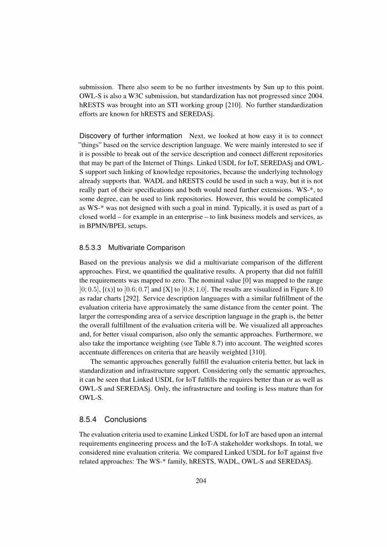
submission. There also seem to be no further investments by Sun up to this point.OWL-S is also a W3C submission, but standardization has not progressed since 2004.hRESTS was brought into an STI working group [210]. No further standardizationefforts are known for hRESTS and SEREDASj.
Discovery of further information Next, we looked at how easy it is to connect”things” based on the service description language. We were mainly interested to see ifit is possible to break out of the service description and connect different repositoriesthat may be part of the Internet of Things. Linked USDL for IoT, SEREDASj and OWL-S support such linking of knowledge repositories, because the underlying technologyalready supports that. WADL and hRESTS could be used in such a way, but it is notreally part of their specifications and both would need further extensions. WS-*, tosome degree, can be used to link repositories. However, this would be complicatedas WS-* was not designed with such a goal in mind. Typically, it is used as part of aclosed world – for example in an enterprise – to link business models and services, asin BPMN/BPEL setups.
8.5.3.3 Multivariate Comparison
Based on the previous analysis we did a multivariate comparison of the differentapproaches. First, we quantified the qualitative results. A property that did not fulfillthe requirements was mapped to zero. The nominal value [0] was mapped to the range]0; 0.5], [(x)] to [0.6; 0.7] and [X] to [0.8; 1.0]. The results are visualized in Figure 8.10as radar charts [292]. Service description languages with a similar fulfillment of theevaluation criteria have approximately the same distance from the center point. Thelarger the corresponding area of a service description language in the graph is, the betterthe overall fulfillment of the evaluation criteria will be. We visualized all approachesand, for better visual comparison, also only the semantic approaches. Furthermore, wealso take the importance weighting (see Table 8.7) into account. The weighted scoresaccentuate differences on criteria that are heavily weighted [310].
The semantic approaches generally fulfill the evaluation criteria better, but lack instandardization and infrastructure support. Considering only the semantic approaches,it can be seen that Linked USDL for IoT fulfills the requires better than or as well asOWL-S and SEREDASj. Only, the infrastructure and tooling is less mature than forOWL-S.
8.5.4 Conclusions
The evaluation criteria used to examine Linked USDL for IoT are based upon an internalrequirements engineering process and the IoT-A stakeholder workshops. In total, weconsidered nine evaluation criteria. We compared Linked USDL for IoT against fiverelated approaches: The WS-* family, hRESTS, WADL, OWL-S and SEREDASj.
204
0,0
0,2
0,4
0,6
0,8
1,0Endpoint support
Business aspects
DistributedDescriptions
Self-Description
Quality ofInformation
Infrastructuresupport
SemanticExtensions
Standardization
Discovery offurther information
LUSDL4IoT WS-* hreST WADL OWL-S SERDASj
(a) All approaches
0,0
0,2
0,4
0,6
0,8
1,0Endpoint support
Business aspects
DistributedDescriptions
Self-Description
Quality ofInformation
Infrastructuresupport
SemanticExtensions
Standardization
Discovery offurther…
LUSDL4IoT OWL-S SERDASj
(b) Semantic Approaches only
0
0,2
0,4
0,6
0,8
1Endpoint support
Business aspects
DistributedDescriptions
Self-Description
Quality ofInformation
Infrastructuresupport
SemanticExtensions
Standardization
Discovery offurther…
LUSDL4IoT WS-* hreST WADL OWL-S SEREDASj
(c) All approaches (weighted)
0
0,2
0,4
0,6
0,8
1Endpoint support
Business aspects
DistributedDescriptions
Self-Description
Quality ofInformation
Infrastructuresupport
SemanticExtensions
Standardization
Discovery offurther information
LUSDL4IoT OWL-S SEREDASj
(d) Semantic Approaches only (weighted)
0,0
0,2
0,4
0,6
0,8
1,0
Infrastructuresupport
SemanticExtensions
Standardization
Discovery offurther information
LUSDL4IoT OWL-S SERDASj(e) Important features, Semantic Approaches only
0,0
0,2
0,4
0,6
0,8
1,0Business aspects
DistributedDescriptions
Self-Description
Quality ofInformation
LUSDL4IoT OWL-S SERDASj
(f) Medium features, Semantic Approaches only
Figure 8.10: Radar charts of the different approaches and the degree they fulfill the evaluationcriteria
205

We showed that Linked USDL for IoT, as a part of the Linked USDL family,fulfills most requirements. Compared to the current gold standard, – that is, the WS-*family – it lacks infrastructure and tooling support, as well as standardization. Inthose two aspects WS-* is clearly superior to all other service description languages.Linked USDL comes with some specialized tooling and can use all RDF-based tools.Nonetheless, the lack of infrastructure and tooling is blatant when compared to the richtooling of WS-*. Only, WS-* has gone through a standardization process. The workon Linked USDL itself was initiated within the W3C USDL Incubator Group. It ismainly driven by SAP, the Knowledge Media Institute of The Open University, and theUniversity of Coimbra.
Linked USDL for IoT is stronger in the area of modeling business aspects. Fur-thermore, it is – naturally – more tailored towards the needs of Internet of Thingsapplications: It supports distributed descriptions, comes with a Quality of Informationvocabulary, and generally offers a better support for semantic extensions. The WS-*protocol family, representing a non-semantic means of describing services, of courselacks any semantic modeling abilities. Extensions for WSDL exist (see Chapter 2.11),but do not have gained widespread adoption.
In comparison with its direct competitors – OWL-S and SEREDASj – it is eitheron par (OWL-S) or even more advanced (SEREDASj). Both, OWL-S and SEREDASj,lack support for business aspects. OWL-S is not specifally tailored towards the needs ofthe IoT, although some research exists. OWL-S did not develop into an integrated suiteof complementary languages, but is more based on isolated research. Development ofthe OWL-S generally seems to have stalled, recently. Tooling support, for examplethe Protegee plugin has not been further development since 2007. Linked USDL has aweb-based marketplace and service editor and currently is under active development.SEREDASj is a relatively new development; it is not specifically made for the IoTas well. It is tightly coupled to JSON and is only a description language (similar toWSDL) and does not come with any vocabularies of its own. Linked USDL for IoTand OWL-S are not tightly coupled to the RESTful paradigm, while SEREDASj solelyis based on a RESTful design.
For industry-wide adoption of Linked USDL for IoT it needs to improve on toolingand standardization. Furthermore, with increasing adoption it would need to be strictlydecided which parts of a service-ecospace should be standardized as part of the LinkedUSDL family of vocabularies, and which parts should be left for external (linked)vocabularies. An open standardization process would prevent users from fearing avendor lock-in and strengthen their belief in a further development of the language.
206

8.6 Experimental Evaluation Framework
We designed a (semi-) automatic toolchain for measuring different properties of IoT ap-plications and protocols within the Mote Runner simulation environment. As discussedin Chapter 2 the Mote Runner system comes with a simulator called Saguaro. Forthe application it is transparent if it runs on a simulated platform or on real hardware.Within the simulation environment measurements of energy consumption and memoryconsumption are possible. Measuring round trip time (RTT) and service access time(SAT) can be done either on hardware or also within the simulation. The definition ofService Access Time is introduced in Chapter 8.6.3. In the following we will presentthe main parts of the experimental evaluation framework.
8.6.1 Simulation Environment
The Mote Runner simulation is a real-time simulation with actual code execution. Thesimulation environment was used to gather the results for the OData evaluation. Further-more, it was used to derive the energy estimations in the sleepy node implementationand for validation of the algorithms.
8.6.2 Memory Usage measurements
The Mote Runner environment provides two tools to measure the memory consumptionof an application. Heap and stack usage can be measured over time. It is possible tostop the execution of the Mote Runner assembly at any possible event and retrievememory usage data. As the Mote Runner environment is controlled and manipulateda script like the one shown in Listing 8.1 is used. It attaches itself to the (memory)frame creation event. Whenever this event occurs the registered listener is called and itretrieves memory information.
Listing 8.1: Memory usage measurements in the Mote Runner simulation environment
for (var i = 0; i < this.motes.length; i++) {var mote = this.motes[i];var conditions = Bugz.args2conds(Saguaro.EV_VM_FRAMESTART, 1);mote.getImpl().programHaltConditions(conditions, BLCK);
}
[...]
var listener = function(/** Sonoran.Event */hev, /** Saguaro.Connection.EventListeners */eventListeners) {
[...]if (evname !== Saguaro.EV_FRAMESTART) {
return;}
for (var i = 0; i < _this.motes.length; i++) {
207

var mote = _this.motes[i];var data = mote.getImpl().inspectResources(BLCK).getReply().
data;var stack = data.vmstack[1];var theap = data.theap[1];if (stack != -1 && stack < _this.freeStack[i]) _this.freeStack
[i] = stack;if (theap != -1 && theap < _this.freeTheap[i]) _this.freeTheap
[i] = theap;}
[...]
The memory measurements produce a human-readable result and, of course, canalso be redirected to disk. The human readable output looks as follows:
Listing 8.2: Memory usage measurements in the Mote Runner simulation environment
---------------------------------------Maximum Resource Usage:---------------------------------------
| STACK | THEAP02-00-00-00-00-5A-E3-D1 | 52 | 536
FREE | 912 | 3256AVAILABLE | 964 | 3792
02-00-00-00-00-5A-E3-D0 | 52 | 536FREE | 912 | 3256
AVAILABLE | 964 | 3792---------------------------------------
The memory usage measurements should not be used together with time-basedmeasurements, as it increases the execution time while recording memory usage data.Therefore, the data gathered for memory and all time-based measurements (energy,access times) were retrieved in different runs.
8.6.3 Service Access Time Measurements
We usually measure the service access time. The service access time is defined asfollows:
Service Access Time (SAT): Service access time (SAT) is the time it takes for a ser-vice request to be sent to the recipient, processed, sent back and decoded by theservice requester.
The SAT can be seen as the service-oriented equivalent of the round trip time.For CoAP calls, and therefore also for OData, we used Californium [218], a CoAPimplementation for more powerful devices, from ETH Z urich. Californium is writtenin Java using heavyweight technologies. Its design goal was not particularly the use onembedded devices, but ease of use from a developers point of view.
208

8.6.4 Energy Measurements
The Mote Runner platform provides a tool that writes a trace of the power consumption.Basically, there are two approaches for estimating the energy consumption: hardware(attached or in circuit) measurements and simulation-based approaches. Approachesbased on hardware rely on additional components on the mote (to provide run-timemeasurement of energy consumption) or it means the complicated and time consuminguse of oscilloscopes and multimeters. Due to the nature of the used devices thesemeasurements are quite accurate. Hurni et al. [179] studied the accuracy of softwarebased estimation compared to sophisticated (in circuit) hardware measurements. Theyreached the conclusion that the while due to inaccuracies in the production of electroniccomponents, differences of more than 4% are possible. Protocol generic, per node cali-brated parameters could reduce the difference to as low as 1.13%± 1.15%. The paperconveys that software-based energy estimation can be a valuable alternative to usingsophisticated measurement hardware. Therefore, software based power consumptionmeasurements are more than feasible when comparing protocols and yield results thatare very close to in circuit measurements.
The energy tracer outputs a given point in time for a specific mote as triple (tn, pn,rn), where tn is a timestamp given in nanoseconds starting from the beginning of thesimulation, pn is the current draw in nano-ampere and rn is the reason for changing theenergy state based on the internal state machine. As soon as the state in the simulationchanges and, thus, the power consumption (current draw), a new triple (tn+1, pn+1,rn+1) is generated.
Figure 8.11: Visualized current trace as produced by the Mote Runnner simulationenvironment
209

A trace, as written by the Mote Runner simulation environment is shown in Listing8.3. The energy traces of different energy states are shown in Figure 8.11. The figureshows the energy trace of a periodic application doing some calculations periodically ev-ery 10 seconds and sending data after every second periode. The radio is in sleep modein between. The peaks at around 1.8∗107nA are the short transmitting phases, the calcu-lations are around 1.4 ∗ 107nA, while the sleeping in between is around 5 ∗ 106nA. TheMote Runner simulation environment, in conjunction with our evaluation framework,allows an a-posteriori analysis and simulation of different hardware characteristics. Weused that feature to simulate different behavior of the Waspmote Pro for scenarios withdeep sleep and without deep sleep.
Listing 8.3: Power measurements in Mote Runner Simulation environment
[nS] [nA] [State]12221068740 17602000 RUN12221100870 7612000 IDL12222352067 17602000 RUN12222370157 12602000 HLT12223346701 17602000 RUN12223346701 12602000 HLT12223346701 17602000 RUN12223346701 20402000 TXING12223351561 10412000 IDL12223922701 20402000 RUN12223922701 17602000 ACTIVE12223925941 7612000 IDL12223925941 17602000 RUN12223947001 16002000 IDLE12223961581 6012000 IDL13222630406 16002000 RUN13223624403 14002000 LED off
Within a given time interval [ta, tb], using an energy consumption function Ψ(t)
and an ordered set of energy level change points p = (t0 = ta, t1, t2, ..., tn = tb) theoverall energy consumption E(ta, tb) can be calculated via discrete integration:
E(ta, tb) =
∫ tb
ta
Ψ(t)dt
=
n−1∑x=0
Ψ(tx) ∗ (tx+1 − tx)
(8.1)
We wrote a tool in Java that takes the output of the Mote Runner simulationenvironment, reads it, performs some operations on the data and outputs the energyconsumption. The framework is shown in Figure 8.12. First, the power measurementstriples (ti, pi, ni) are read, then some processing can be done one the data, like filteringfor different motes or applying a different energy profile. This is particularly useful for
210
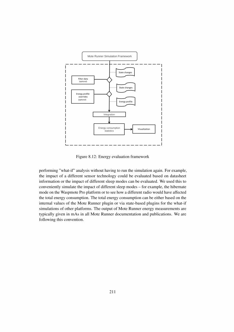
Mote Runner Simulation Framework
Integration
Energy profile overrides (optional)l)
State changes
Energy profile
Energy consumption
statistics
Filter data (optional)
State changes
Visualization
Figure 8.12: Energy evaluation framework
performing ”what-if” analysis without having to run the simulation again. For example,the impact of a different sensor technology could be evaluated based on datasheetinformation or the impact of different sleep modes can be evaluated. We used this toconveniently simulate the impact of different sleep modes – for example, the hibernatemode on the Waspmote Pro platform or to see how a different radio would have affectedthe total energy consumption. The total energy consumption can be either based on theinternal values of the Mote Runner plugin or via state-based plugins for the what-ifsimulations of other platforms. The output of Mote Runner energy measurements aretypically given in mAs in all Mote Runner documentation and publications. We arefollowing this convention.
211

8.7 OData Stack
In this section we perform a quantitative analysis of our OData implementation and,consequently, the CoAP implementation. We are using the software (Mote Runner) andhardware (IRIS) as described in Chapter 2. First, we present the experimental settingthat was used to perform our experiments (Chapter 8.7.1). As outlined in Chapter6.3.2.1 we are communicate with the mote directly. The enterprise system has directaccess to the mote and communicates with it without an intermediary gateway.
8.7.1 Experimental Setting
IRIS
(Odata)CoAPUDP
MRv6
Mote Runner
(OData)CoAPTCPIPv6
Edge mote IoT-device
IRISEnterprise
System
Enterprise
wired
wireless
Stac
k
Stac
k
Figure 8.13: Experimental setting
All experiments were conducted with IRIS motes. The technical details and spec-ifications of the IRIS mote can be found in Chapter 2.1.2. All measurements wereperformed within the Mote Runner simulation environment. We were only interestedin scenarios, in which the mote communicates directly with the enterprise systemfollowing the Internet-of-Things vision. No application-layer gateway was used. Theexperimental setting is shown in Figure 8.13. The motes were running the Mote Runnerv11 with a 6LoWPAN network stack, as shown in Figure 6.3. The Mote Runner v116LoWPAN stack is tailored towards predictability and not optimized for low energyconsumption or high throughput. Some optimization-potential has been addressedwith later versions of MRv6. Please refer to Chapter 2.3.3 for more details on MRv6.We assume our results to be generalizable to other platforms and protocols as well,because the ratios between sending, receiving, sensing and using CPU time should becomparable on all platforms.
8.7.2 Mote Setup
The OData service we are exposing consists of one mote with three different sensors(temperature, humidity and light), where each has a unique ID, a name and can return a
212

value (data). As outlined in Chapter 6.3, service discovery is done through the servicedescription and the metadata information. The service description of our service looksas follows:
Listing 8.4: ”OData Service”
<?xml version="1.0" encoding="utf-8" ?><service xml:base="http://tmpsvc.sap.com/OData.svc/" xmlns="http
://www.w3.org/2007/app" xmlns:atom="http://www.w3.org/2005/Atom">
<workspace><atom:title>Default</atom:title>
- <collection href="Sensors"><atom:title>Sensors</atom:title>
</collection></workspace>
</service>
The JSON representation is more compact and therefore more suitable for con-strained devices:
Listing 8.5: ”OData Service - JSON”
{"odata.metadata":"http://tmpsvc.sap.com/OData.svc/\$metadata","value":[{"name":"Sensors","url":"Sensors"}]}
The $metadata keyword, which provides information about the sensors looks asfollows:
Listing 8.6: ”OData Service - metadata”
<?xml version="1.0" encoding="utf-8"?><edmx:Edmx Version="1.0" xmlns:edmx="http://schemas.microsoft.com/
ado/2007/06/edmx"><edmx:DataServices m:DataServiceVersion="3.0" m:
MaxDataServiceVersion="3.0" xmlns:m="http://schemas.microsoft.com/ado/2007/08/dataservices/metadata">
<Schema Namespace="Mote" xmlns="http://schemas.microsoft.com/ado/2009/11/edm">
<EntityType Name="Sensor"><Key><PropertyRef Name="ID" /></Key><Property Name="ID" Type="Edm.Int32" Nullable="false" /><Property Name="Name" Type="Edm.String" m:FC_TargetPath="
SyndicationTitle" m:FC_ContentKind="text" m:FC_KeepInContent="false" Nullable="false" />
<Property Name="temp" Type="Edm.String" m:FC_TargetPath="SyndicationSummary" m:FC_ContentKind="text" m:FC_KeepInContent="false" Nullable="true"
<ValueAnnotation term="Measurements.Unit.Celsius"></property>
213

<Property Name="humi" Type="Edm.String" m:FC_TargetPath="SyndicationSummary" m:FC_ContentKind="text" m:FC_KeepInContent="false" Nullable="true" />
<ValueAnnotation term="Measurements.Unit.Humidity"></property>
<Property Name="lght" Type="Edm.String" m:FC_TargetPath="SyndicationSummary" m:FC_ContentKind="text" m:FC_KeepInContent="false" Nullable="true" />
<ValueAnnotation term="Measurements.Unit.Light"></property><Property Name="data" Type="Edm.String" m:FC_TargetPath="
SyndicationSummary" m:FC_ContentKind="text" m:FC_KeepInContent="false" Nullable="true" />
<ValueAnnotation term="Measurements.Unit"></property><EntityContainer Name="APPService" m:IsDefaultEntityContainer="
true"><EntitySet Name="Sensors" EntityType="Mote.Sensor" /></EntityContainer>
The metadata encodes that our mote has entities (in OData notation) of typeMote.Sensor. These entities have certain properties (ID, name, and data) as wellas corresponding datatypes. Furthermore, the set Sensors as specified in the servicedescription is further defined to be of type Mote.Sensor. The $metadata request inOData v3 is only specified for ATOM/XML. OData v3 does not support the metadatadocument as part of a JSON representation. As per OData v4 the JSON representationis also supported now. The responses of the motes are based on that schema.
Listing 8.7: ”OData service- sample response: ATOM”
<d:temp xmlns:d="http://sap.com/dataservices" xmlns:m="http://coap/metadata">24</d:temp>
The same result in JSON verbose format [272] would look as follows:
Listing 8.8: ”OData service - sample response: JSON”
{"odata.metadata":"[::::1]/OData.svc/$metadata#Edm.String","temp":"24"}
As baseline for a system that is not OData-enabled, we choose pure CoAP asapplication layer protocol with a small data representation. This baseline could be usedas data representation in an external service description such as Linked USDL for IoT.In the following we will refer to this baseline simply as CoAP, in comparison to JSONand ATOM. The message representation in the CoAP baseline is then in the form ofcomma delimited property:value pairs, as shown in the following code fragment:
Listing 8.9: ”OData payload - sample CoAP response”
214

id:<sensor_no>,n:<sensor_name>,d:<value>
A means of discovery resources is the CoRE Link Format[349], accessible throughthe .well-known/core interface. There is a subtle difference between the ./well-known/coreand OData service discovery: the CoRE Link Format supports Resource Discovery,while OData aims for Service Discovery. The CoRE Link Format provides web linkingas specified in RFC5988[281] and can be used to discover the links hosted by a CoAPserver. It returns information in a link-header style format [ 281]. A minimal resourcedescription for a similar resource based access to the mote could look as follows:
Listing 8.10: ”OData Service - metadata in Core Link Format”
</temp>;rt="temperature";ct=0;if="sensor"</hum>;rt="humidity";ct=0;if=sensor,</light>;rt="light";ct=0;if="sensor"
First, the resource is named – in this case ”/temp”, for temperature sensor. Then theresource type (rt) and the content type (ct). The rt attribute is string used to assign anapplication-specific semantic type to a resource [349]. In case the CoRE-Link Formatis used in conjunction with Linked USDL for IoT, it can be used for linking the two.The interface ”if” specifies the interface to be used, in our case sensor. This is also anapplication specific string. The ct attribute specifies the content type, as described inthe CoAP specification [354]. A content type of zero means plain text.
Q1 GET coap://[]:1024/OData.svc?$metadataQ2 GET coap://[]:1024/OData.svc/sensorsQ3 GET coap://[]:1024/OData.svc/sensors(0)Q4 GET coap://[]:1024/OData.svc/sensors(0)/IDQ5 GET coap://[]:1024/OData.svc/sensors(0)/NameQ6 GET coap://[]:1024/OData.svc/sensors(0)/tempQ7 GET coap://[]:1024/OData.svc/sensors?$filter=
Data gt 42Q8 GET coap://[]:1024/OData.svc/sensors?$filter=
Data eq 60 and Name eq humidity
Table 8.9: Queries
8.7.3 Results
In the following we investigate a typical IoT-scenario in which a backend system isdirectly communicating with the mote. The queries used to evaluate the properties ofthe system are listed in Table 8.9. The computational complexity increases with eachQi. In the rest of the work we will refer to these queries as Qm
i or Qmi, where i isthe query number as listed in Table 8.9, and m is either A for OData/ATOM, J forOData/JSON and C for CoAP, with or without the compression suffix CP
215

0,00E+00
1,00E+03
2,00E+03
3,00E+03
4,00E+03
5,00E+03
6,00E+03
7,00E+03
8,00E+03
Q4 Q5 Q6 Q3 Q8 Q7 Q2 Q1
Serv
ice
Acce
ss T
ime
(in
ms)
Query
ATOM JSON COAP
Figure 8.14: Service access time (in ms, blockwise-transfer with block size 64 Byte)for queries Q1 to Q8 sorted by QA
n payload size
Query ATOM ATOM/CP JSON JSON/CP COAP
Q1 1627 1164 — — 115Q2 1643 906 191 156 63Q3 604 443 110 105 23Q4 99 96 74 74 4Q5 94 88 85 84 13Q6 87 82 76 76 4Q7 1199 734 148 100 39Q8 761 523 108 108 18
Table 8.10: Payload size (in Bytes), compressed (CP) and uncompressed
The resource consumption of the on-mote implementation is shown in Table 8.11.It is seen that the memory consumption of the OData/ATOM implementation is largerthan the memory consumption of JSON. Nonetheless, the JSON implementation iscomparable to a pure CoAP implementation in terms of resource consumption. Wedid not optimize for resource consumption – for example, some memory blocks werepre-allocated to have a big enough table available for sensor data and the dictionary,and might not be actually used. More aggressive implementations are possible. Onlystack and heap are critical because the IRIS platform offers only 8kb of which nearlyhalf is already used by the Mote Runner VM. Flash is not that much of an issue on thehardware platform. The IRIS mote offers 128KB of program flash and another 512KBof data flash. The actual payload of each query is shown in Table 8.10.
For each query Q1...Q8 we measured the service access time, that is, the time froma request being issued by the the service consumer until the answer has been decoded.The results (averaged over 100 runs) are shown in Figure 8.14 for uncompressed data
216

COAP JSON ATOM
Stack Heap Flash Stack Heap Flash Stack Heap Flash
Q1 232 3271 3850 — — — 292 3543 4255Q2 232 3284 3850 292 3460 3931 292 3552 4255Q3 232 3252 3850 292 3432 3931 292 3476 4255Q4 232 3244 3850 292 3436 3931 292 3408 4255Q5 232 3248 3850 292 3440 3931 292 3496 4255Q6 232 3248 3850 292 3448 3931 292 3416 4255Q7 232 3316 3850 292 3500 3931 292 3524 4255Q8 232 3404 3850 292 3528 3931 292 3548 4255
Table 8.11: Memory consumption (maximum, in bytes)
and in Figure 8.15 for compressed data. For small result sets the difference betweenthe three formats is negligible. Larger data sets change the situation. Compression candecrease the service access time considerably for large ATOM requests and, to somedegree, the JSON requests. CoAP and JSON remain at low service access times, but theATOM format increases the service access time rapidly because of the amount of datato be transmitted. Compression does help in case of ATOM, but is still considerablyworse than JSON. It reduces the energy consumption and the service access times, butnot to a degree where it could compete with JSON or even CoAP. Devices that are lessconstrained would profit from more advanced compression schemes. Unfortunately,OData v3 does not support a metadata JSON representation, so at least once a downloadof the metadata is necessary.
The CoAP block size also affects the service access time. A 6LoWPAN packet, evenif fragmented, is typically more efficient than the CoAP block option in settings that donot suffer packet loss and when WSN links do not suffer from congestion often [ 240].In such cases they show a better performance than the CoAP block option. Nonetheless,in cases of packet loss or when fragmentation is not available or exceeds the capabilitiesof the system, CoAP blockwise transfer can be used. Furthermore, block-wise transferhas the additional advantage that allows the server to be stateless. A block-wise transferdoes not need any connection setup or memory of previously sent blocks. Most highlyconstrained devices are running on so few memory that the handling of additional stateand possible caching of packets would exceed their capabilities. In our implementationwe therefore rely mainly on the CoAP block option. The relationship between CoAPblock sizes and the resulting service access times are shown in Figure 8.16. Earlynegotiation of block sizes is assumed. The simulation was idealistic as we assumed nopacket loss, and minimal to no application-related overhead (e.g. sensing) that mightcause later transmission. Due to limitations of the MRv6 protocol [180], we did nottake the overhead of the IP-layer fragmentation or the adaption-layer fragmentation intoaccount, but only the transmissions and receptions of packets. The VM-based approachof Mote Runner might have added some delays as we do not control the hardware. It is
217

possible that the VM delays sending by a slot or two (e.g. garbage collection, differenttasks running). Other than that, the response times typically did not vary by more than afew slots for the same amounts of packets send when running with the MRv6 protocol.
We experimented with non-standard block sizes (see also Chapter 2.5) to estimatethe effects of an unconstrained block size negotiation. As shown, the effects wererelatively low. So, the restriction is sufficient. The main factor reducing the responsetime is the number of new block requests. A block size of 32 bytes, of course, requirestwice as many new block requests than a 64 byte block size.
0,00E+00
5,00E+02
1,00E+03
1,50E+03
2,00E+03
2,50E+03
3,00E+03
3,50E+03
4,00E+03
4,50E+03
5,00E+03
Q4 Q5 Q6 Q3 Q8 Q7 Q2 Q1
)sm ni( e
mit ssecca ecivreS
Query
ATOM/CP JSON/CP COAP
Figure 8.15: Service access time (in ms, blockwise-transfer with block size 64 Byte)for queries Q1 to Q8 (compressed) sorted by QA
n payload size. CoAP (see also Figure8.14) as baseline for comparison (always uncompressed)
The energy consumption evaluations were performed within our simulation en-vironment. In Figure 8.17 and Figure 8.18, we show the energy consumption ofOData/ATOM, OData/JSON and CoAP once for a block size of 64 bytes and 256 bytes.As can be seen, the advantages of a more machine-readable and machine-interpretabledata representation is payed with higher energy consumption. The ATOM responseneeds most energy, for the obvious reason of more air time, but also as there are manytransfers from flash memory to RAM. The energy consumption of JSON, and especiallyJSON/CP, is comparable or only slightly higher than the CoAP baseline. Smaller blocksizes lead to more data transfer for the block requests and responses, as well as morecomputation to process these requests and thus an increase in energy consumption.The advantage of a smaller block size is increased reliability and in case of very lossynetwork increased throughput. Furthermore, they avoid fragmentation on lower layers.
8.7.4 OData versus Linked USDL
In the following we will briefly compare OData and Linked USDL for IoT. They followdifferent design philosophies, which leads to certain strengths and weaknesses. The
218

0
1E3
2E3
3E3
4E3
5E3
6E3
64 128 192 256 320 384 448 512 576 640 704 768 832 896 960 1024
Service Access Time (Pr
Q1 Q2 Q3 Q4 Q5 Q6 Q7 Q8
[ms]
[Byte]
Figure 8.16: Service access times of queries QA1 to QA
8 with different CoAP block sizes(simulation, idealistic values)
0,00E+00
5,00E+03
1,00E+04
1,50E+04
2,00E+04
2,50E+04
3,00E+04
3,50E+04
ATO
M
ATO
M/C
P
JSO
N
JSO
N/C
P
CoAP
ATO
M
ATO
M/C
P
JSO
N
JSO
N/C
P
CoAP
ATO
M
ATO
M/C
P
JSO
N
JSO
N/C
P
CoAP
ATO
M
ATO
M/C
P
JSO
N
JSO
N/C
P
CoAP
ATO
M
ATO
M/C
P
JSO
N
JSO
N/C
P
CoAP
ATO
M
ATO
M/C
P
JSO
N
JSO
N/C
P
CoAP
ATO
M
ATO
M/C
P
JSO
N
JSO
N/C
P
CoAP
ATO
M
ATO
M/C
P
JSO
N
JSO
N/C
P
CoAP
Q1 Q2 Q3 Q4 Q5 Q6 Q7 Q8
)SAm( notp
musnoc ygrneE
Figure 8.17: Energy consumption (in mAs, serving a series of 100 requests, blocksize64 Byte)
main advantage of OData is its industrial support. Unlike Linked USDL, it prescribes adata representation. Linked USDL for IoT provides far richer modeling possibilities. Ithas a more comprehensive service idea – for example, it allows model business aspects,human work, and interaction patterns among other things. As discussed in Chapter6.3.3.2 for reasoning purposes, a mapping from OData to RDF can be performed.OData is more than just a service description, it is also a query language. Linked USDLfor IoT is not designed to work on that level. Extending Linked USDL for IoT withcomplex query capabilities might also not be desirable. However, further extensions ofLinked USDL for IoT that allow modeling such query interfaces easily are possible.
A Linked USDL implementation that uses JSON-LD as data representation wouldhave approximately the same resource consumption and general behavior as we ob-served in the OData/JSON case. Linked USDL for IoT is able to ”semantify” our CoAP
219

0,00E+00
5,00E+03
1,00E+04
1,50E+04
2,00E+04
2,50E+04
ATO
MAT
OM
/CP
JSO
NJS
ON
/CP
CoAP
ATO
MAT
OM
/CP
JSO
NJS
ON
/CP
CoAP
ATO
MAT
OM
/CP
JSO
NJS
ON
/CP
CoAP
ATO
MAT
OM
/CP
JSO
NJS
ON
/CP
CoAP
ATO
MAT
OM
/CP
JSO
NJS
ON
/CP
CoAP
ATO
MAT
OM
/CP
JSO
NJS
ON
/CP
CoAP
ATO
MAT
OM
/CP
JSO
NJS
ON
/CP
CoAP
ATO
MAT
OM
/CP
JSO
NJS
ON
/CP
CoAP
Q1 Q2 Q3 Q4 Q5 Q6 Q7 Q8
)sAm( noitp
musnoc ygrenE
Figure 8.18: Energy consumption (in mAs, serving a series of 100 requests, blocksize256 Byte)
baseline as well. Each mote has a core link format description and a Linked USDLservice description, similar to Listing 5.18. Thereby, the energy and service accesstimes could be reached by using Linked USDL as external service describing, linkingthe result sets to their respective semantics. In case of more complex result sets, ofcourse, the size of the Linked USDL payloads and the necessary modeling effort wouldalso increase.
8.7.5 Conclusions
We performed an experimental feasibility study on the applicability of OData on Class0 devices. Based on the terminology we introduced in Chapter 1.1, this representsa top-down approach for enabling REST-based interoperability in a semantics-awareenterprise. As shown, there is a considerable energy overhead of ATOM/XML overthe CoAP baseline. The SATs are also much higher and they render the ATOM rep-resentation as an almost impossible choice for battery-powered constrained devices.Compression significantly improved both the SAT and the energy consumption. Incase of a Class 0 device, it is still not feasible unless the device communicates veryinfrequently. Given our experimental platform, we could not improve much on this.Class 1 and higher devices could benefit from more advanced ATOM/XML represen-tations using XMI and other technologies. More details can be found in Chapter 2.8.Nonetheless, compared to JSON the advantage of the baseline shrinks. The differencebetween JSON/JSON-CP and CoAP is the price to be paid for an enterprise protocol onan IoT-node. The overall energy consumption was comparable. The CoAP baseline didconsume significantly less energy than ODATA, but typically not significantly less thanthe JSON or JSON/CP representation. In terms of SAT, the JSON representation wasbetween 1.38 and 2.62 times the respective SAT of the COAP baseline. JSON/CP hadSATs between 1.20 and 2.62 times the baseline. Of course, as shown in Chapter 2.8,real performance gains from the compressed versions are to be expected for larger datasets when lot of sensor data has to be transmitted. For exampleQ7, where the amountof data was reduced to three thirds of the original, the SAT time immediately decreased
220

by around the same. The critical $metadata information, one of the weak points ofOData v3, decreased from around 6.0 times the baseline to 4.0 times the baseline. Froma pure SAT and energy point of view, this makes the bottom-up approach using LinkedUSDL for IoT more attractive. In contrast, the use of an industry standard increasesinteroperability immediately, without the need for Linked USDL. One is then, of course,limited to the semantic expressiveness of OData. A major drawback of OData v3 isthe fact that the $metadata, thus the place were all the semantics is provided, has norepresentation in JSON and thus always needs to be transmitted as ATOM/XML. Thesituation changed with OData v4 so that future OData implementations on IoT systemscan benefit from a $metadata JSON representation.
8.8 Sleepy Nodes
In the following, we present the evaluation results of the sleepy node framework asdescribed in Chapter 7. First, we describe the experimental setup. We proceed bydetermining the constants in our energy model and discussing the impact of clock drift.Afterwards, we evaluate our implementation and the three allocation strategies withinthe windowing framework.
8.8.1 Experimental Setup
We used a network of seven nodes (n0...n6) – including the sink (n0) – in a binary treelayout running the MRv6 protocol (see Chapter 7.5). We simulated Waspmote PROsand IRIS Motes with hardware capabilities as explained in Chapter 2. If not specifiedotherwise, the following default parameters were used to run the experiments:
In most experiments we assumed the energy state for all the nodes as follows(n0, ..., n6) = (∞, 2Eleaf , 2Eleaf , Eleaf , Eleaf , Eleaf , Eleaf ). For leaf nodes we as-sumed either EES1 ≡ Eleaf=10J, EES2 ≡ Eleaf=100J or EES3 ≡ Eleaf = 2000J .The results scaled well with different energy values. The sink was assumed to haveinfinite power reserves and therefore the power consumption on it was ignored.
A variable number of entities was used, 8 ± 3, the entities measurement periodsvaried from 3*103 seconds to 7 ∗ 103 seconds. The experimental setup is a scaleddown version of a supply chain or warehouse scenario, with rather frequent monitoringof perishable goods, or medicine that allows time for longer sleeping periods. Themeasurement tolerance per entity was up to 20% of its measurement period. Thewindow size used was equal to the mean measurement period. 50% of the entities couldbe measured by 2 sensors, 30% by 3 and 20% by 4. The assignment of eligible sensorsto entities according to the above percentages was done by sampling from a uniformrandom distribution. All the values presented in the results are typically averages amonga number of runs (up to 15), using the same parameters. For every run the randomnumber generator was initialized with a different seed. We used the Monte Runnerenvironment v14.
221

8.8.2 Energy Model
To be able to compare different sensor selections for some given measurements, we haveto be able to calculate the energy that would be spent on each node of the WSN. Weapproximate this by using the linear energy model (Chapter 7.4). From a computationalpoint of view, as this is only an estimation based on a linear model, the calculation takesvirtually no time. The energy model, as shown in the following formula, was alreadydiscussed in Chapter 7.4.
En = tnidle · Pidle + tnsleep · Psleep︸ ︷︷ ︸time based
+mnsense · Esense +mn
sleep · Esleep +mncomm · Ecomm︸ ︷︷ ︸
event based
In this chapter, we present the actual values we derived for the two hardwareplatforms. The simulation framework allows us to measure durations, states and currentdraw. Furthermore, we can control the input parameters, in particularly the numberof requests, and the time in protocol sleep and protocol idle mode; therefore, we canuse ordinary least squares (OLS) regression analysis [ 314] to determine the unknownvariables in our linear equation.
The general idea is to model a variable (En) as a linear function of others. OLSminimizes the sum of squared errors between the estimations by applying the modeland observations as measured in simulation. En has been measured, as well as tsleepand tidle. The number of requests msense, msleep, and mcomm have been varied. Forboth platforms (IRIS and Waspmote), we performed a large number of (automated)experiments over several hours to get enough data to fit our model. In the end, we gothundredths of Megabytes of Data. Every experiment was repeated in four differentmodes of network operation, so that we could extract correlated and uncorrelatedfeatures for approximating the different energy components of our model. The differentmodes of operation were:
• Querying and Sleeping: Normal mode of operation. Nodes are put to sleepbetween measurements.
• Querying Only: Only measurement queries are issued. The nodes are not put tosleep between measurements.
• Sleeping Only: Only sleep requests are issued. No measurements are performed.
• Idle Only: The network is initialized and left in the idle state for the wholeduration of the experiment. Neither queries nor sleeping requests are issued forany of the nodes. There is no network activity other than the one imposed by theMRv6 protocol itself.
222

For all components given in Equation 8.8.2 we derived the following energy andpower values:
Esense = 4.62891 ∗ 10−3J
Esleep = 3.45422 ∗ 10−3J
Ecomm = 6.82133 ∗ 10−4J
Psleep = 3.60 ∗ 10−5W
P baseidle = 1.70 ∗ 10−2W
Pneighboridle = 4.64 ∗ 10−4W
IRIS
Esense = 1.99402 ∗ 10−3J
Esleep = 6.30984 ∗ 10−3J
Ecomm = 5.27001 ∗ 10−4J
Psleep = 6.00 ∗ 10−6W
P baseidle = 1.71 ∗ 10−2W
Pneighboridle = 4.61 ∗ 10−4W
Waspmote Pro
We used two-thirds of the data to determine the parameters in our equation andone-third of it for validating our model with two metrics: the mean absolute percentageerror and the coefficient of determination. The mean absolute percentage error (MAPE)is defined as
MAPE =1
n
n∑i=1
∣∣∣∣Vi − V i
Vi
∣∣∣∣ ∗ 100 (8.2)
where Vi is the actual value of the observation and V i its statistical forecast. MAPEexpresses its accuracy as a percentage and describes how large the mean absolutepercentage error is. Its lower bound is zero and it has an unlimited upper bound. Alower value means a better match of the actual observation and its statistical forecast.
The coefficient of determination R2 indicates how well the data fits its statisticalforecast as well. R2 is defined as:
R2 = 1−∑n
i=1(Vi − V i)2∑n
i=1(Vi −AV G(V ))2(8.3)
The coefficient ranges from zero to one. The closer the coefficient is to one, thebetter the fit. A coefficient of one means a perfect fit.
We calculated for IRIS motes:
MEAPIRIS = 1.09
R2IRIS = 0.99951
(8.4)
223

and for the Waspmote Pro Platform:
MEAPWaspmote = 1.71
R2Waspmote = 0.99903
(8.5)
Both metrics show, for both platforms, a good fit between the expected value andthe simulated value. In the following, the simulated sleepy node algorithms use theenergy model with those derived parameters.
8.8.3 Clock-Drift and Energy Considerations
We have already discussed clock drift and its consequences in Chapter 7.5.2. Now, wequantify its impact on energy consumption. Clock-drift is important because it preventsa node to wake-up at the exact calculated moment. Depending on the clock-drift thecalculated and the actual clock-drift can differ substantially. Calculations are presentedin Chapter 7.5.2.
At this point, we are solely looking at the impact on energy consumption. Theenergy consumption of a mote that is sleeping and about to wake up and rejoin thenetwork is shown in Figure 8.19. The least energy is consumed if the node wakes up atexactly the right time, catches the beacon and immediately joins the network. This isillustrated in the graphs at point ppm=0. Assuming a clock-drift of, for example, 10ppman additional 0.008J is spent on the IRIS mote (see Figure 8.19). In an experiment weobserved that the maximum energy overhead caused by drift is in the order of 1 ∗ 10−2Jper 5000 seconds sleep request. As can be seen, clock-drift that causes the mote towake up earlier than required is typically better than clock-drift that will cause missingthe beacon. A miss just after the beacon forces the mote to keep listening for a nearlyfull beacon interval.
8.8.4 Sleepy Node Implementation
In the following, we present the results of the conducted experiments based on thethree strategies introduced in Chapter 7: first Fit, an exhaustive approach, and dynamicpartitioning. The three strategies can be summarized as follows. For further detailsplease refer to Chapter 7.6.3
Exhaustive Strategy (ea): The optimal solution for the task allocation problem,with regard to our energy model and within the given window, is computed by applyingan exhaustive approach (backtracking with constrained satisfaction). An exhaustiveapproach considers all possible partitions of the set Mw and evaluates them. It hasexponential time complexity.
First Fit (ff): As a second benchmark for comparison, we use a first-fit algorithmoperating within the same windowing framework. It creates a new query for everymeasurement, picking one of the eligible sensors at random.
224

IRIS WASPMOTE PRO
−30 −20 −10 0 10 20 30Clock drift (in ppm)
0.240
0.242
0.244
0.246
0.248
0.250
0.252
0.254
Ener
gy c
onsu
mpt
ion
(in jo
ules
)
−30 −20 −10 0 10 20 30Clock drift (in ppm)
0.088
0.090
0.092
0.094
0.096
Ener
gy c
onsu
mpt
ion
(in jo
ules
)
Figure 8.19: Energy consumption for node answering a 5000s sleep request, sleepingfor that amount of time and then waking up. The chosen beacon interval here is 250ms.For the largest drifts of 25 ppm presented, the clock offset over 5000 seconds is 125 ms.
Dynamic Partitioning (dp): Instead of considering all possible partitions, weorder the measurements Mw according to their timestamps and check only the ones thatcombine neighboring measurements in a greedy way. The rationale for this strategy isthe observation that measurements that can be combined often appear in sequence.
In the presentation of the results we normalized the window sizes (ws) and toler-ances according to the mean entity measurement period. For ws=0.5, therefore theactual length of a window in seconds (Lwindow) was half of mean(ω). For ws = 2,Lwindow was twice mean(ω).
ws =← Lwindow
mean(ω)
tolerancee ←e.δi
mean(ω)∀e ∈ G
To compare the two platforms in a better way, we typically normalized the energyand network lifetimes with respect to the maximum value of the IRIS mote. As describedin Chapter 7.6, the task-allocation algorithm tries to take advantage of the knowledge ofthe measurement timings and sensor distribution, in order to reduce energy overhead bycombining measurements into the same query. Therefore, the capability of a possiblecombination relies on two factors (see Chapter 7):
1. the entities tolerances
2. the sensors overlapping
225

IRIS WASPMOTE PRO
0.2
0.3
0.4
0.5
0.6
0.7
0.8
0.9
1
0 0.5 1 1.5 2
lifet
ime(
norm
aliz
ed)
window size
exhaustivedynamicpartitioning�rst �t
(a)
0.2
0.4
0.6
0.8
1
1.2
1.4
1.6
0 0.5 1 1.5 2
lifet
ime(
norm
aliz
ed)
window size
exhaustivedynamicpartitioning�rst �t
(b)
Figure 8.20: Comparison of the different task allocation algorithms, IRIS Platform (lefthand side) and Waspmote Pro platform (right hand side), EES1. The window size isexpressed relatively to the mean entity measurement period
Figure 8.20 presents a comparison of the allocation strategies (first fit, dynamicpartitioning, exhaustive). The metric for lifetime was defined as the time until thefirst node ”dies” because of energy depletion. The simulated lifetimes are idealistic.The battery technology, timing and intensity of the applied load and the physicalenvironments have an impact on the actual lifetime, as demonstrated by Feeney et al.[121].
The exhaustive algorithm is only slightly better than the dynamic partitioningapproach. This renders the latter a very good approximation. The lifetime gain forlonger windows is substantial even in the case of the first fit algorithm, where nomeasurement combinations occur. This is due to all the nodes waking up at the endof each window, which induces considerable energy costs. The longer the windowsare, the more rarely the scheduling has to be performed. Hence, the nodes can sleepfor longer periods before they have to wake up again for the scheduling of the nextwindow. This also explains why the other two strategies do not perform significantlybetter than the first-fit strategy for small window sizes (< 1): For very small windowsizes there was not much of a difference between the three strategies, because therewere not enough opportunities to go to sleep at all. For larger window sizes (>= 1) thefirst-fit strategy reached significantly lower lifetimes than the other two strategies. Onthe Waspmote Pro and with a window size of two, for example, first-fit only reachedaround 60% of the lifetime of the other two strategies.
It is obvious that the Waspmote platform is superior in terms of network lifetimedue to its better energy characteristics and better real-time clock. The lifetime of theapplication on the Waspmote Pro platform was around 1.5 times the lifetime on the
226
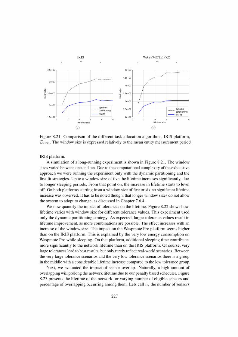
IRIS WASPMOTE PRO
1.5e+07
2e+07
2.5e+07
3e+07
3.5e+07
0 2 4 6 8 10
lifet
ime(
s)
window size
dynamicpartitioning�rst �t
(a)
2e+07
2.5e+07
3e+07
3.5e+07
4e+07
4.5e+07
5e+07
0 2 4 6 8 10lif
etim
e(s)
window size
dynamicpartitioning�rst �t
(b)
Figure 8.21: Comparison of the different task-allocation algorithms, IRIS platform,EES3. The window size is expressed relatively to the mean entity measurement period
IRIS platform.A simulation of a long-running experiment is shown in Figure 8.21. The window
sizes varied between one and ten. Due to the computational complexity of the exhaustiveapproach we were running the experiment only with the dynamic partitioning and thefirst fit strategies. Up to a window size of five the lifetime increases significantly, dueto longer sleeping periods. From that point on, the increase in lifetime starts to leveloff. On both platforms starting from a window size of five or six no significant lifetimeincrease was observed. It has to be noted though, that longer window sizes do not allowthe system to adopt to change, as discussed in Chapter 7.6.4.
We now quantify the impact of tolerances on the lifetime. Figure 8.22 shows howlifetime varies with window size for different tolerance values. This experiment usedonly the dynamic partitioning strategy. As expected, larger tolerance values result inlifetime improvement, as more combinations are possible. The effect increases with anincrease of the window size. The impact on the Waspmote Pro platform seems higherthan on the IRIS platform. This is explained by the very low energy consumption onWaspmote Pro while sleeping. On that platform, additional sleeping time contributesmore significantly to the network lifetime than on the IRIS platform. Of course, verylarge tolerances lead to best results, but only rarely reflect real-world scenarios. Betweenthe very large tolerance scenarios and the very low tolerance scenarios there is a groupin the middle with a considerable lifetime increase compared to the low tolerance group.
Next, we evaluated the impact of sensor overlap. Naturally, a high amount ofoverlapping will prolong the network lifetime due to our penalty based scheduler. Figure8.23 presents the lifetime of the network for varying number of eligible sensors andpercentage of overlapping occurring among them. Lets call ns the number of sensors
227

IRIS WASPMOTE PRO
0.2
0.3
0.4
0.5
0.6
0.7
0.8
0.9
1
0 1 2 3 4 5 6
lifet
ime
(nor
mal
ized
)
window size
tolerance = 0.00tolerance = 0.05tolerance = 0.10tolerance = 0.20tolerance = 0.25tolerance = 0.50tolerance = 0.75tolerance = 1.00
(a)
0
0.5
1
1.5
2
0 1 2 3 4 5 6
lifet
ime
(nor
mal
ized
)window size
tolerance = 0.00tolerance = 0.05tolerance = 0.10tolerance = 0.20tolerance = 0.25tolerance = 0.50tolerance = 0.75tolerance = 1.00
(b)
Figure 8.22: network lifetime vs window size for different tolerance values. IRISplatform (left hand side) and Waspmote Pro platform (right hand side), EES1, bothtolerance and window size are expressed relatively to the mean entity measurementperiod
that is indicated by the different lines in the plot. The overlapping percentage expressesthe percentage of entities that could be measured by ns sensors. The remaining entitiesin this series of experiments could only be measured by one sensor. For example, for50% overlapping, we get the result of an experiment where 50% of the entities can bemeasured by three different sensors and the rest can only be measured by one. Similarlyto when varying the tolerance, considerable improvement in lifetime is observed whenthe number of sensors eligible to measure the entities is increased and more overlappingbetween them occurs. The penalty-based sensor allocation (see Chapter 7.6.2) ensuresthat all sensors are more or less equally utilized.
8.8.4.1 Dynamic Behavior of the System
We now evaluate the dynamic behavior of the system, as explained in Chapter 7.6.4.First, we add an arbitrary incoming measurement that is unknown to the system.Second, we extend our evaluation by assuming the system has some knowledge aboutthe probability distribution of the incoming, otherwise unknown, measurements overtime. We use the concept of virtual measurements as explained in Chapter 7.6.4.2.
Dynamic incoming measurements, as introduced in Chapter 7.6.4, are served byadding separate requests that are unknown to the scheduler at the time of scheduling.The scheduler has to dynamically do a best effort integration into its plan or schedulethem for the next window. We modeled those incoming measurements, for each e ∈ E,by adding new measurements reusing the existing experimental framework.
228
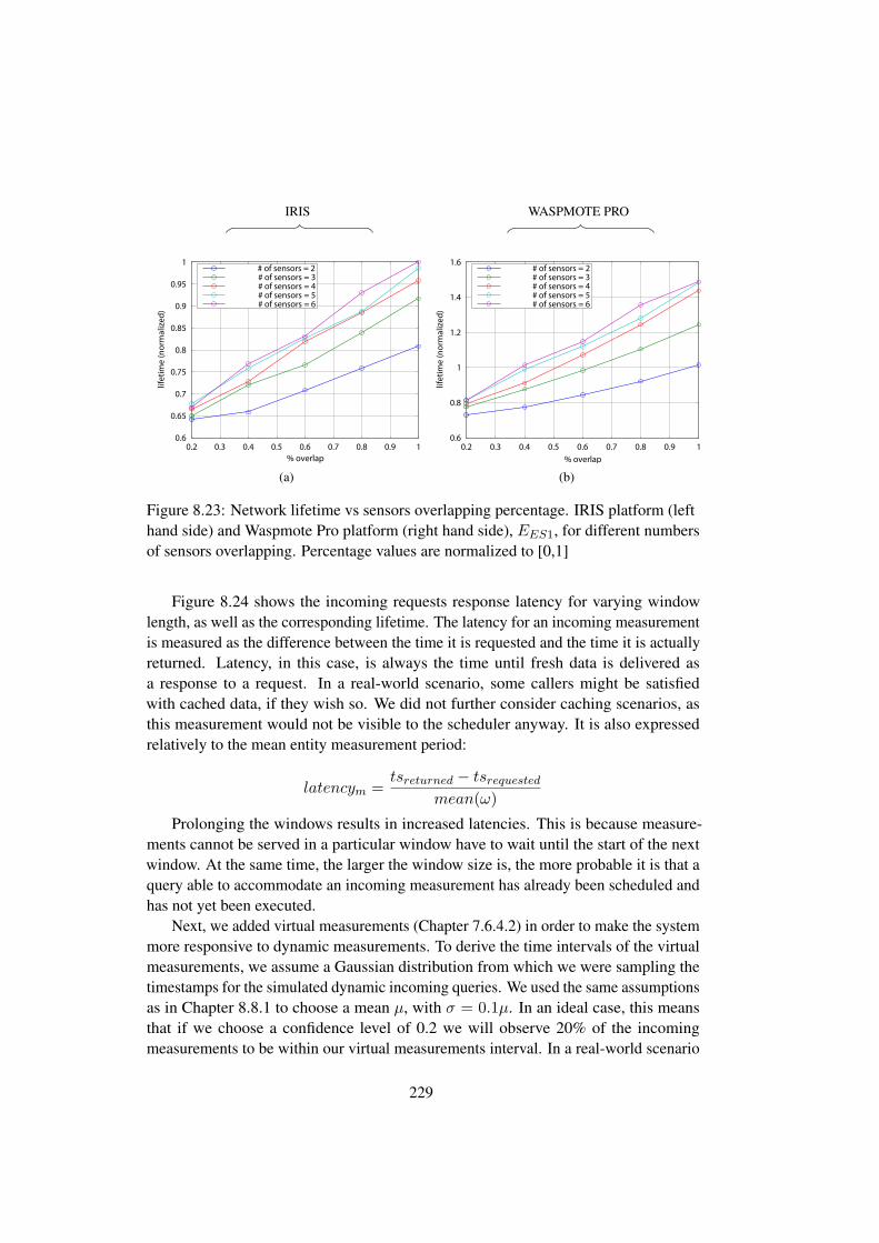
IRIS WASPMOTE PRO
0.6
0.65
0.7
0.75
0.8
0.85
0.9
0.95
1
0.2 0.3 0.4 0.5 0.6 0.7 0.8 0.9 1
lifet
ime
(nor
mal
ized
)
% overlap
# of sensors = 2# of sensors = 3# of sensors = 4# of sensors = 5# of sensors = 6
(a)
0.6
0.8
1
1.2
1.4
1.6
0.2 0.3 0.4 0.5 0.6 0.7 0.8 0.9 1lif
etim
e (n
orm
aliz
ed)
% overlap
# of sensors = 2# of sensors = 3# of sensors = 4# of sensors = 5# of sensors = 6
(b)
Figure 8.23: Network lifetime vs sensors overlapping percentage. IRIS platform (lefthand side) and Waspmote Pro platform (right hand side), EES1, for different numbersof sensors overlapping. Percentage values are normalized to [0,1]
Figure 8.24 shows the incoming requests response latency for varying windowlength, as well as the corresponding lifetime. The latency for an incoming measurementis measured as the difference between the time it is requested and the time it is actuallyreturned. Latency, in this case, is always the time until fresh data is delivered asa response to a request. In a real-world scenario, some callers might be satisfiedwith cached data, if they wish so. We did not further consider caching scenarios, asthis measurement would not be visible to the scheduler anyway. It is also expressedrelatively to the mean entity measurement period:
latencym =tsreturned − tsrequested
mean(ω)
Prolonging the windows results in increased latencies. This is because measure-ments cannot be served in a particular window have to wait until the start of the nextwindow. At the same time, the larger the window size is, the more probable it is that aquery able to accommodate an incoming measurement has already been scheduled andhas not yet been executed.
Next, we added virtual measurements (Chapter 7.6.4.2) in order to make the systemmore responsive to dynamic measurements. To derive the time intervals of the virtualmeasurements, we assume a Gaussian distribution from which we were sampling thetimestamps for the simulated dynamic incoming queries. We used the same assumptionsas in Chapter 8.8.1 to choose a mean µ, with σ = 0.1µ. In an ideal case, this meansthat if we choose a confidence level of 0.2 we will observe 20% of the incomingmeasurements to be within our virtual measurements interval. In a real-world scenario
229

IRIS WASPMOTE PRO
0.2
0.3
0.4
0.5
0.6
0.7
0.8
0.9
1
0 0.5 1 1.5 2 2.5 3
lifet
ime
(nor
mal
ized
)
window size
(a)
0.2
0.4
0.6
0.8
1
1.2
1.4
1.6
0 0.5 1 1.5 2 2.5 3
lifet
ime
(nor
mal
ized
)
window size
(b)
Late
ncy
window size(c)
window size
Late
ncy
(d)
Figure 8.24: Network lifetime and latency vs window size, IRIS platform (left hand side) andWaspmote Pro platform (right hand side),EES1. The window size is expressed relatively to themean entity measurement period.
230

this could be an intelligent container moving along the supply chain that is expectedto reach waypoints at a given time, but the actual arrival cannot be precisely detected– for example, because of traffic. Figure 8.25 provides an overview of the changein the network lifetime and the latency of the incoming measurements when virtualmeasurements with varying confidence levels are used for different window sizes. It isseen that with increasing required confidence levels, the gain from prolonging windowsis very small compared to the loss from keeping the nodes awake with the virtual queries.The higher the required confidence level, the longer the node has to be switched on,waiting for the query, resulting in higher energy consumption and thus lower networklifetime. The lower the confidence levels, the higher the latency due to missed wronglyassumed virtual measurements.
This trade-off between network lifetime and the reduction of the incoming measure-ments latency is shown in Figure 8.26. The effect is quite strong, as high confidencelevels lead to high duty-cycles and few sleeping periods. If network lifetime is the keyproperty of a system, then it should be designed in such a way that, as far as thesearbitrary incoming messages are concerned, either the system is provided with a verygood estimation of when the actual measurements will happen with lower deviationsthan the one we assumed, or such that latency is not an issue. A system, where thesensor measurement can be predicted with a deviation of only a few seconds or it is nothappening at all otherwise, might work well with large confidence levels. Furthermore,a protocol with a better idling energy footprint than MRv6 should be considered.
8.8.4.2 Packet Loss
Packet loss, as mentioned in Chapter 7.6.5, may cause measurements to miss theirdeadlines and impacts network lifetime. In the experiment presented in Figure 8.27we varied the percentage of packet loss from low to high for five different tolerances(5s, 10s, 25s, 50s and 100s). The closer the tolerance is to the round-trip time the morelikely a deadline miss is to occur. Nonetheless, even small tolerances are still somewhatresilient towards deadline misses for relatively small to moderate packet loss rates. Thenetwork lifetime is relatively independent of the tolerance. Naturally, it is very sensitiveto packet loss. In harsh and loosy environments the system architect would have toadapt the combination logic of the dynamic partitioning algorithm: measurements couldbe excluded from the combining algorithm if the remaining time were be smaller than agiven threshold, to ensure that a retry is possible within the time constraints.
231

IRIS WASPMOTE PRO
0
0.2
0.4
0.6
0.8
1
0 0.2 0.4 0.6 0.8 1
lifet
ime
(nor
mal
ized
)
con�dence level
window size = 0.20window size = 0.50window size = 1.00window size = 1.50window size = 2.00
(a)
0
0.5
1
1.5
2
0 0.2 0.4 0.6 0.8 1
lifet
ime
(nor
mal
ized
)
con�dence level
window size = 0.20window size = 0.50window size = 1.00window size = 1.50window size = 2.00
(b)
0
0.05
0.1
0.15
0.2
0.25
0.3
0.35
0 0.2 0.4 0.6 0.8 1
late
ncy
con�dence level
window size = 0.20window size = 0.50window size = 1.00window size = 1.50window size = 2.00
(c)
0
0.05
0.1
0.15
0.2
0.25
0.3
0.35
0 0.2 0.4 0.6 0.8 1
late
ncy
con�dence level
window size = 0.20window size = 0.50window size = 1.00window size = 1.50window size = 2.00
(d)
Figure 8.25: Network lifetime and incoming measurements latency vs virtual measurementsconfidence level, IRIS Platform (left hand side) and Waspmote Pro platform (right hand side),EES2, for different window lengths
232
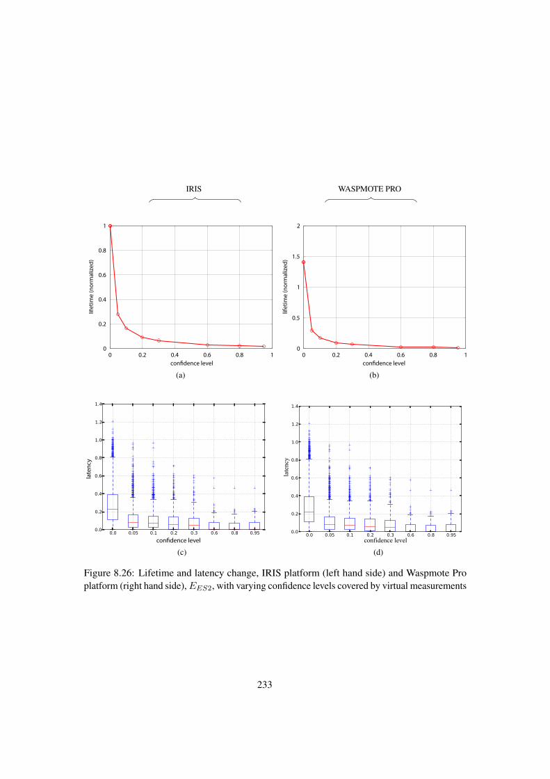
IRIS WASPMOTE PRO
0
0.2
0.4
0.6
0.8
1
0 0.2 0.4 0.6 0.8 1
lifet
ime
(nor
mal
ized
)
con�dence level
(a)
0
0.5
1
1.5
2
0 0.2 0.4 0.6 0.8 1
lifet
ime
(nor
mal
ized
)
con�dence level
(b)
con�dence level
late
ncy
(c)
late
ncy
confidence level
(d)
Figure 8.26: Lifetime and latency change, IRIS platform (left hand side) and Waspmote Proplatform (right hand side),EES2, with varying confidence levels covered by virtual measurements
233

IRIS WASPMOTE PRO
0
0.2
0.4
0.6
0.8
1
0 0.2 0.4 0.6 0.8 1
perc
enta
ge o
f mea
sure
men
ts m
issi
ng d
eadl
ine
packet loss (percentage)
tolerance = 5 stolerance = 10 stolerance = 25 stolerance = 50 stolerance = 100 s
0
0.2
0.4
0.6
0.8
1
0 0.2 0.4 0.6 0.8 1
perc
enta
ge o
f mea
sure
men
ts m
issi
ng d
eadl
ine
packet loss (percentage)
tolerance = 5 stolerance = 10 stolerance = 25 stolerance = 50 stolerance = 100 s
0
0.2
0.4
0.6
0.8
1
0 0.2 0.4 0.6 0.8 1
lifet
ime
(nor
mal
ized
)
packet loss (percentage)
tolerance = 5 stolerance = 10 stolerance = 25 stolerance = 50 stolerance = 100 s
0
0.2
0.4
0.6
0.8
1
0 0.2 0.4 0.6 0.8 1
lifet
ime
(nor
mal
ized
)
packet loss (percentage)
tolerance = 5 stolerance = 10 stolerance = 25 stolerance = 50 stolerance = 100 s
Figure 8.27: Percentage of measurements made outside entities tolerance and network lifetimefor varying percentage of packets lost and tolerance values. EES1. Percentage values arenormalized to [0,1]
234
8.8.5 Conclusions
We presented the evaluation results of our application-layer sleepy node implementationas introduced in Chapter 7. Our experimental platform, Mote Runner, started to supporta second platform – Waspmote Pro – with Mote Runner beta13. Based upon our on-motesimulation and evaluation framework (Chapter 8.6) we evaluated our implementation onIRIS and Waspmote Pro motes. A modern platform such as Waspmote Pro provides ahuge benefit compared to previous platforms with regard to mid- and longterm sleeping,due to its advanced sleep states.
First, we derived a hybrid energy model that is used to calculate the savings ofa deep sleep compared to idling. Within our windowing-based framework (Chapter7.6) we evaluated three different strategies: a first fit, an exhaustive strategy and aheuristic named dynamic partitioning. The dynamic partitioning heuristic is based onthe observation that measurements that can be combined (executed together) are oftensequential in time. We have shown that the dynamic partitioning approach does notperform significantly worse than an exhaustive (optimal) approach and considerablybetter than a simple first fit. It could be shown that the sleepy nodes implementationon Waspmote Pro achieved an enhanced network lifetime that was up to 50% higherthan on IRIS motes. Without sleeping, the energy consumption for idling and runningis comparable on both platforms. One of the main problems with sleepy nodes is thatthey cannot respond to any request while sleeping; thus, they, cannot react in a dynamicenvironment. We also evaluated our system in such dynamic scenarios: first, by justusing the next available mote (if any) to serve a request in this window. Second, weassumed that the system knows the probability of a request, but not its exact timing. Tocope with them, we introduced virtual measurements. The measurements are calledvirtual, because at the time of scheduling its not yet clear when they will becomereal measurements. The scheduling algorithm now keeps the mote on for the timeperiod specified by the virtual measurements in order to increase the responsivenessof the system. Our experiments have shown though, that such a strategy – whileindeed increasing the responsiveness – decreases the network lifetime significantly. Itis important that system designers carefully choose a window size that matches theirrequirements concerning network lifetime. The less often the system changes, thebetter and the more soft their real-time requirements are. Higher tolerances allow thealgorithm to combine more measurements and, therefore, save energy.
Knowledge about this long term sleeping periods cannot be derived easily by themotes themselves, or by a network-layer protocol. A semantics-aware enterprise canbenefit from the knowledge of its entities to maximize the energy savings. Sleepynodes, in conjunction with a windowing-based framework, allow the system to maintaina degree of flexibility in order to adapt to a changing environment. Sleepy nodescan benefit from a semantic platform in various ways. First, the data stored aboutentities and positions can be derived easily. In addition, the dynamic behavior can besignificantly improved if the system is able to reason about upcoming measurementrequests. In combination with learning algorithms that leverage on the semantic data
235
and gathered data, patterns could be deduced that improve the forecast of measurementsand adopt virtual measurements accordingly.
8.9 Conclusions
In this chapter, we presented the evaluation results of our work. We applied empiricaland experimental research methodologies. Our empirical evaluation stands on threepillars: first, an internal requirements gathering process (internal stakeholders anddomain experts); second, a broader and structured requirements gathering process basedupon the IoT-A stakeholder workshops; third, a survey on the use of semantics in theIoT. In addition, we applied an architecture evaluation methodology to gain insightinto the strengths and weaknesses of our proposed architecture. The experimentalevaluation is based on the Mote Runner platform running JAVA-based applications. Weprototyped our CoAP, OData and Sleepy Node implementation and measured, amongothers, response times and energy.
The proposed architecture has been evaluated using an architecture evaluationmethodology based on SAAM [198] and extended with industry best practices. Themethodology is described in Chapter 8.1. Our scenario-based architecture analysisshowed that the architecture generally fulfills the requirements. It is flexible enough toaccommodate a variety of changes. The semantic-awareness approach using LinkedServices fits the needs of enterprises well. However, we also identified some risks. Thearchitecture and its components are not well suited for hard real-time requirements.Additional effort is necessary to adopt it accordingly and to introduce mechanisms tosupport hard real-time requirements.
The stakeholder workshops and the survey generally showed an expected moveof IoT-applications towards standardization – mainly towards REST-based systemsbuilt upon IP-technology (6LoWPAN) – and an increased interest in semantics. Thestakeholder workshops and the survey were conducted in a community that traditionallyworked with 802.15.4 networks, we especially did not survey mobile (as in IPad orIPhone) related developments. The use of specialized protocols, which traditionallyplayed an important role in the IoT community, is declining. They are expected to bealmost completely replaced by already existing standards. On the application layer theparticipants were split when asked if today’s application-layer protocols sufficientlysupport the special needs of IoT-applications. All other layers are clearly expected tomove towards standards. One explanation could be that the large payloads generated byapplication-layer protocols and their processing complexity are beyond the constraintsof those devices. The energy and processing power needed to use protocols such asSOAP is a magnitude higher than of simple protocols such as CoAP. Furthermore, inthe past a lot of research has been done on the network, transport and the MAC-layer.The lack of standardized application-layer protocols could also be because the IoT-market is still yet to be established. Initiatives, for general-purpose application-layerprotocols like CoAP are relatively new. Different future solutions – for example, in the
236

area of home automation, could compete and finally converge towards a standard. Ofcourse, with better battery technology coming up and the availability of more low-powerplatforms, it is also possible that traditional technologies like HTTP, its successors, orSOAP will play a major role even in future (constrained) IoT-applications. The need forgeneral-purpose specialized IoT-protocols thus might vanish and applications, which areso constrained that they cannot run such a protocol, will then use a specialized protocoland an application gateway solution. The use of semantics is anticipated and some needfor it seems to be recognized, mainly driven by the anticipation of machine-learningsystems. Of course, the the enterprise community is very much interested in suchopportunities. A more traditional ”bit-and-byte”-oriented community as, for example,automotive might have a different view. The results might not be easily generalizable todomains other than an enterprise/ERP community. We also looked into a phenomenoncalled semaphobia[225] – the observation that many developers are somewhat reluctantto use semantic technologies, even if they see benefit in it. The top reason, most of ourparticipants assumed to be responsible for this effect, are knowledge and awareness ofthe development staff, followed by a lack of standardization.
We compared Linked USDL for IoT with related approaches based on a set ofcriteria. Our criteria-based evaluation shows that Linked USDL for IoT fulfills mostrequirements. Compared to the current gold standard, – that is, the WS-* family –it lacks infrastructure and tooling support, as well as standardization. In those twoaspects WS-* is clearly superior to all other languages, including Linked USDL for IoT.Nonetheless, Linked USDL for IoT is stronger in the area of modeling business aspects.Furthermore, it is — naturally — more tailored towards the needs of Internet of Thingsapplications: it supports distributed descriptions, comes with a Quality of Informationvocabulary, and generally offers a a better support for semantic extensions. The WS-*protocol family, representing a non-semantic means of describing services, of courselacks any semantic modeling abilities. In comparison with its direct competitors, OWL-S and SEREDASj, it is either on par (OWL-S) or even more advanced (SEREDASj).Both, OWL-S and SEREDASj, lack support for business aspects. Besides, SEREDASjis currently tightly coupled to JSON. For industry-wide adoption of Linked USDL forIoT it needs to improve on tooling. An open standardization process would preventusers from fearing a vendor lock-in and strengthen their belief in a further developmentof the language.
As part of our architecture, we prototyped two protocols on the Mote Runnerplatform: CoAP and OData. OData was chosen as a top-down approach for makingsemantics available on constrained IoT-devices. Our proof-of-concept implementationshowed that OData can be made available to such devices. We compared OData in itstwo representations JSON and ATOM/XML with a CoAP baseline. The CoAP baselinecould be made semantics-aware using Linked USDL. Therefore, it can be seen as apossible data representation in a bottom-down approach. The difference between thebaseline and OData representation can be considered the price to be paid for semanticson our IoT-platform. The ATOM/XML representation is possible, but both its power
237

consumption and its service access times are order of magnitudes larger than withJSON or the CoAP baseline. Compression improves the situation for queries withlarger payloads and reduces both the power consumption and the service access times.In the case of the ATOM representation compression reduced large payloads, as themandatory $metadata, from around 6.0 times the baseline to 3.8 times the baseline.
The JSON representation performed better and was close to the CoAP baseline,but on average also had a relative penalty of between 1.2 and 2.6 times the CoAP SATvalue. Compression did not contribute much in the JSON case for small payload sizes.In the worst case it still needed around twice as much time as the CoAP representation.The energy consumption was much lower than the energy consumption of ATOM, andoften as good or only slightly worse than the CoAP baseline. The still widely usedOData protocol v3 has the drawback that the overall metadata cannot be specified inJSON representation, because it is undefined. This changed with OData v4. The changewill make it even more suitable for IoT-applications. Considering that our IoT-platformis on the lower end of the spectrum (a Class 0 device), OData can be expected to be aneven more viable alternative on more powerful devices.
We evaluated our sleepy node implementation. The application-layer sleepy nodeimplementation serves as an example of how a semantics-aware enterprise can benefitfrom the information available at the application layer, for example in a supply chainor warehouse scenario. The sleepy node architecture and implementation integrateswell into our proposed platform. Our experiment was based on two IoT-platforms: IRISand Waspmote Pro. The Waspmote Pro has an advanced sleep state that consumes onlyvery little energy and thus achieved considerably higher energy savings than the IRISplatform. First, we had to extend the existing MRv6 implementation to to allow mid- tolongterm sleeping periods. The challenge here was to integrate into the beacon-basedprotocol and to calculate a wake-up point that is close to the expected next beacon aftersleeping. We derived a hybrid energy model for both platforms. The energy model canbe used to calculate beneficial sleep times. We were able to show the general benefit ofapplication-layer sleepy nodes. We experimentally evaluated three different strategies:a first fit, an exhaustive approach and a heuristic named dynamic partitioning. Wedemonstrated that within a time-sliced (windowed) environment this heuristic – basedupon combinable subsequent measurements – further reduces the energy consumption.It achieved only slightly worse network lifetimes than the exhaustive approach andgenerally performs better than first fit. The windowing approach we used has somebenefits and some drawbacks. Beneficial for the calculation of the sleeping periods isthat no changes to the system are expected. This allows an calculation of the sleepingperiods. Nonetheless, this is also one of the major drawbacks: Changes to the systemcan only be done at the beginning of each window. Larger window sizes have shown toincrease the network lifetime, therefore there is a trade-off to be made between windowsize and the number of possibilities to change the system.
For requests that arrive between two windows one naive approach would be to justschedule it for the next window and inform the requester. Another way of handling such
238

situations would be to return cached data and information about the age of the data. Weexperimented with two different scenarios: we try to serve arbitrary incoming requestsanyway, and we consider requests that are expected i.e. a known probability distributionexists. In the first case we try combine the request with an already known measurementand schedule the request there, or look into the communication paths for a suitable node.If no such node exists, we resort to the naive strategy of scheduling it starting from thenext window. For requests were such a node exists, the data can be served earlier thanby waiting for the next window. We also tested scenarios in which we assume to knowthe probability distribution of some expected requests. We still want to leverage onsleeping, instead of keeping the node on all the time waiting to serve the request. Weschedule therefore some virtual measurements i.e. measurements that might becomereal queries. For the virtual measurements we specified confidence levels. The higherthe confidence level the longer we wait for the query. Virtual measurements reducethe time we need to answer the requests that would otherwise be handled like arbitraryrequests. Nonetheless, the higher the confidence level the smaller the network lifetime.Therefore, a good estimation of the time frame the requests arrives is necessary for longnetwork lifetimes.
239

240

Part V
Conclusions and Outlook
In this part of the thesis we summarize our work and present the main conclusions.We also provide on Outlook presenting opportunities for further work.

242

Chapter 9
Conclusions and Outlook
Semantics-aware integration and REST-based services are considered major challengesin future enterprise scenarios coined as theSensing Enterprise. The Internet of Things,still being a relatively constrained environment, is currently in the lead with regardto applying semantic technologies. More and more vendors, such as Google, areentering the field with semantic technologies. This thesis explored various aspects ofthe service-based integration of IoT-devices into a semantics-aware enterprise. Wepresented conceptual and architectural work on IoT-services, and their integrationinto semantics-aware enterprises. Based on our integration platform we explored twoapproaches of semantics-aware enterprise integration: a bottom-up approach and atop-down approach. The bottom-up approach semantically enriches existing protocols.It is based on Linked USDL for IoT, a service description language specifically tailoredtowards the needs of the IoT. We developed Linked USDL for IoT as an extension of theLinked USDL family of vocabularies. The top-down approach is based on an alreadyexisting semantics-aware enterprise protocol which we moved to and evaluated onconstrained devices. Furthermore, we discussed possibilities of modeling IoT-specificentities and properties with OData.
We extended our proposed integration platform to support also sleepy nodes. Sleepynodes are IoT-devices that go to sleep, but still appear as connected to the user. Weintroduced a windowing-based measurement framework supporting three allocationstrategies: a first-fit, an exhaustive approach and a self developed heuristic calleddynamic partitioning. We were able to show that dynamic partitioning performssignificantly better than first fit and only slightly worse than the exhaustive approach.We also investigated how a window-based framework can react to requests that areunknown at the beginning of a particular window.
9.1 Conclusions
In Chapter 3, we conducted a literature survey on definitions and usages of servicesin the Internet of Things. At the beginning of our work, we realized that the termIoT-service was often used in an intuitive way and that its relationship to the Internet
243
of Things in general was unclear. We suggested a definition of Internet of Thingsservices that differs from the more common idea of using service as a synonym fortechnical interface. Our definition based on the term ”transaction” that is consistent withdefinitions found in service science. The classification and the surrounding conceptsare centered on the entity and not that much on the technical representations or meansof realization through low-level services. This idea guides the work on Linked USDLfor IoT, which we introduced in Chapter 5. We presented conceptual work on thearchitectural building blocks and design considerations for an Internet of Things serviceintegration framework. We showed how services can be integrated into the Internet ofThings-Architecture, which is semantics-aware.
Chapter 4 built on the ideas of Internet of Things-services in general and describedhow they can be embedded into an enterprise environment. We presented an architecturefor an IoT-aware enterprise, typically named the sensing enterprise. Its novelty is thecombination of two concepts – linked services and distribution – which, when combined,serve the needs of both enterprises and small constrained IoT-devices. We argue that(distributed) linked services are especially well suited for IoT-applications given theirlimited battery power, as well as storage and processing constraints. They allow only aminimal subset of the service description to be stored on the mote. More information canbe accessed on-demand. We identified the key drivers that will drive enterprises in thecoming years, namely: interoperability, use of standardized technologies, enablementof sense-making, and realtime business decision support. Especially interoperability,sense making, and real-time business support would benefit from semantic servicedescriptions and linked services. We suggest an abstraction named semantic physicalbusiness entity, which can be used in enterprise architectures and especially in modelingenvironments.
Linked USDL for IoT, our extension of Linked USDL for supporting the Internetof Things, is presented in Chapter 5. It has the advantage of being a service descriptionlanguage that goes beyond the technical interface. It consists of different modules thatcover functional, operational and business aspects. In addition, it allows the usageof already existing domain specific vocabularies, because it is modeled in RDF. Weextended Linked USDL to support REST-based IoT technical interfaces and propertiesthat are IoT-specific. We contribute four new vocabularies to Linked USDL to supportInternet of Things applications. Each of this vocabularies targets a specific aspect ofthe Internet of Things. The covered aspects are events, quality of information, technicalendpoints and the REST paradigm. Furthermore, we embedded it into related ontologies.We evaluated Linked USDL for IoT by performing a criteria-based evaluation and amultivariate comparison. We identified nine key properties a service description for theIoT should have and their importance. The criteria-based evaluation compares LinkedUSDL for IoT to related approaches, namely WS-*, hRESTS, WADL, OWL-S andSEREDASj. The multivariate comparison also takes the importance of the propertiesinto account. In the IoT-domain, we showed – based on our nine properties – anadvantage of RDF-based languages over traditional XML-based technologies. Linked
244

USDL for IoT is one of the few approaches that have light-weight design principlesin mind. To some degree, however, it lacks tool support and standardization. In thesetwo aspects (tool support and standardization) WS-* can be seen as gold standard andLinked USDL for IoT and similar approaches will have to catch up.
Our empirical results are supported by a survey, stakeholder workshops, and internalexperts. In particular, we were interested in the acceptance of semantics in the IoT,and its relationship to IoT-technologies. We can conclude that, within the surveyedgroup, there is a strong expectation towards the future enterprise IoT to be based onRESTful paradigms supporting standards known from the Internet community. On theapplication-layer the participants were split when asked if today’s application-layerprotocols sufficiently support the special needs of IoT-applications. One explanationcould be that the large payloads generated by application-layer protocols and theirprocessing complexity are beyond the capabilities of those devices. HTTP, for example,is quite verbose. It remains open in our opinion if advances in hardware and newdevelopments on the web (like HTTP/2 or SPDY) will reduce the need for a general-purpose IoT application-layer protocol, or if the IoT-community will have its ownprotocol stack. It is interesting that Enterprises move towards IoT-protocols, instead ofmoving enterprise protocols (as SOAP) towards IoT. The observation that semanticswhile being advocated for many years now still did not gained widespread use couldbe explained by the lack of training and the fact that the first generations of computerscientist educated in semantic web just entered the enterprises. In general, most peoplesee potential for semantics in the Internet of Things and expect usages starting fromdescribing things and services up to reasoning on a semantic layer.
As explained in Chapter 1.4 our IoT-stack is based on CoAP as application-layerprotocol. We implemented a CoAP solution on the Mote Runner platform. In particular,we implemented the base specification [353] and two extensions: block-wise transfer[352] and observe [162]. We implemented the CoAP protocol (like all our software) inJava. On one hand, it was quite an advantage because the ramp-up time was quite low,compared to – for example – nesC. On the other hand, however, it was counter-intuitiveto work with the CoAP specification which is based on unsigned datatypes. The use ofJava in low-level and protocol programming would, in our opinion, greatly benefit fromunsigned types. For allowing (distributed) linked services some kind of redirectionpossibility is desirable, similar to what HTTP offers. CoAP does not have this propertyat the moment. We therefore discussed for possible solutions: 3.xx message codes,CoAP options, Content Type and Data encoding. We concluded that, while the 3.xxfamily might be the most desirable, currently the most promising solution is to movethe problem to the application itself. In our opinion this is a gap in the standard thatneeds to be addressed in future CoAP releases.
We evaluated a top-down approach by using an existing semantics-aware enterpriseprotocol and applied it to Class 0 IoT-motes. We propose the OData protocol as anend-to-end solution for the integration of REST-based sensor networks into enterpriseIT systems. We concentrated on direct communication with the Mote. Interoperability
245

with enterprise systems is one of main arguments for using OData. On the downside,one has to stay within the modeling capabilities of OData: OData currently offers fewersemantic modeling abilities than description languages based on RDF. It was coined”semi-semantic” by some people, because of its lack of integration into the semanticweb. This seemed to be definitely justified for OData v2, already less justified for ODatav3. With OData v4, semantic annotations are fully supported. Notably, the ODataentity abstraction fits a typical sensor network usage very well, including abstractingthe topology and the sensors (or actors) as entities. This makes OData a very goodabstraction for systems that can be seen as sensor network databases. Querying thesensor network becomes easily possible, as well as accessing temporal data. Moreover,these can be carried out in a standardized RESTful way that is immediately accessibleby other applications. Compared to Linked USDL for IoT OData follows a close-worldassumption. Linked USDL for IoT is better integrated into the semantic world andleverages on semantic technologies and linking well known vocabularies together. Acombination or integration of Linked USDL and OData, or more general RDF-basedlanguages and OData, is a current research field.
We implemented a proof-of-concept OData-enabled prototype on the IRIS platform.The difference in resource usage and transmission time between the baseline and ODatarepresentation can be considered the price to be paid for semantics on our IoT-platform.The ATOM/XML representation is possible, but both its power consumption and itsservice access times are order of magnitudes larger than with JSON or the CoAPbaseline. Compression improves the situation and reduces the power consumption andthe service access times. In the case of the ATOM representation compression reducedlarge payloads, as the mandatory $metadata, from around 6.0 times the baseline to 3.8times the baseline. Nonetheless, in most cases it is still considerably higher than theJSON or CoAP representation. For a single temperature query with a minimal ATOMrepresentation, it needed 40% more time than JSON and around twice (93% more)the time of the baseline. The JSON representation for this single temperature call wasaround one third slower than the CoAP baseline.
The JSON representation, in general, performed better and was close to the CoAPbaseline, but on average still was in the range of 1.2 to 2.6 times the CoAP SATvalue depending on the query. Compression did not contribute much in the JSONcase for queries resulting in small payload sizes. This is to be expected though, as(dictionary-based) compression needs more and repetitive data to perform better andsignificantly reduce the payload. For example Q7, a query with a lot of payloadwhere the amount of data could reduced to three thirds of the original: the SATtime immediately decreased by around the same and also power consumption wasreduced significantly. The effect is expected. As shown in Chapter 2.8, a strengthof general-purpose compression algorithms are large amounts of sensor data [110].Therefore, OData as a sensor database with queries that return a lot of data, for examplecollected over a day, will almost certainly benefit strongly from the general purposecompression. Within a very constrained environment, as provided by the IRIS platform,
246

the differences between the resource usage in terms of memory, processing time andenergy consumption of ODATA/JSON, compared to a pure CoAP solution, could beconsidered small enough to justify the benefits of a full semantic integration, while theATOM representation is clearly not feasible unless for small use-cases. ODATA/JSONproved to be a worthwhile alternative to pure CoAP solutions, providing enterprisesand other systems direct access to data-driven IoT-devices. In contrast to the CoAPbaseline solution, direct and standardized access the to semantic information is possible.Moreover, for an enterprise system a sensor node or a wireless sensor network is justanother datasource that can be used in business processes, just like any other datasourcewithout the need for adapters or special low-level information. XML processing shouldbe avoided. JSON was superior to ATOM in almost every aspect. Transmission oflarge ATOM files should be, if possible, redirected to a system with more performancecapabilities.
In addition to interoperability, energy efficiency is one of the major issues in wirelesssensor system. The concept of sleepy nodes, as defined by IETF [313], is relativelynew in the community. Sleepy nodes are sensor nodes that might be in an energysaving mode for some time and thus not available for any communication, but, bydefinition, a sleepy node should appear as being connected to the network to the user.In Chapter 7 we present an implementation of a Sleepy Nodes extension to our IoT andsemantics-aware enterprise architecture. Sleepy nodes can leverage on the semanticknowledge stored in enterprise repositories to save energy. Our prototype system wasrunning on two hardware platforms: MEMSIC Iris and Waspmote Pro. The WaspmotePro has a more precise clock and a hardware deep sleep mode. Compared to the IRISplatform, which does not have such a deep sleep mode, the Waspmote Pro platformhad a significantly longer lifetime. We derived a hybrid energy model, combiningtime-based aspects and event-based aspects, for both hardware platforms to calculatebeneficial sleeping times. We were able to show that our model predicts the actualenergy consumption quite accurately. The MRv6 implementation had to be modified tosupport mid- and longterm sleeping periods. The wakeup time had to be calculated tobe as close to a beacon as possible, thus reducing the time a node has to keep his radioon.
We compared three different allocation strategies: exhaustive, first fit and a self-developed heuristic, which we named dynamic partitioning. As expected, the exhaustiveapproach performed best, but is only feasible for a small number of sensors and entities.Within the constraints of the windowing-based framework the dynamic partitioningapproach performed significantly better than the first-fit algorithm, and only slightlyworse than the exhaustive approach. We also adopted our windowing-based system tocope with requests that are either unknown at the beginning of a window or only theprobability of a request is known in advance. We introduced the concept of a virtualmeasurement, allowing the system to guess the arrival of a request. This increasesthe responsiveness of the system, but sacrifices a lot of energy. Keeping the mote onin order to wait for a virtual measurement to become a real measurement has a large
247

impact on the system lifetime and thus should preferably only be used if the period inwhich a virtual measurement becomes a real measurement is small.
9.2 Outlook
The Internet of Things is expected to grow tremendously over the next decade. Gartnerpredicts $2.5M per minute in IoT spending and 1M new IoT devices sold every hourby the year 2021. We expect significant growth not only in the consumer sector, butespecially in the enterprise sector.
Linked USDL for IoT currently is capable to describe services in the IoT followinga REST-based input/output concept. Having semantically-enriched services is a pre-condition for many upcoming applications. We hope that the vocabulary is taken up bythe semantics community and further integrated into reasoning and machine learningscenarios. Furthermore, non REST-based endpoints could be added to increase thecompatibility with legacy enterprise systems. Interoperability between systems couldbe further improved by automatically generate endpoints depending on the application.It would then be possible to generate, for example, a SOAP/WSDL endpoint in additionto a REST endpoint.
We proposed a semantics-aware enterprise architecture and some modeling conceptsthat center around semantics. We would encourage further work on modeling IoT withsemantics in a BPMN-context and its automatic execution. Engines and concepts (suchas SPBQL) need to be fully specified and integrated into an business process executionframework. We would like to see experimental results of such a platform. Furtherwork on the distribution of service descriptions, versioning and the combination ofdistributed service descriptions would also be worthwhile.
OData is an upcoming semantics-aware protocol, which can also play a major role inIoT-applications. Our experiments were conducted with OData v3 and should be movedto OData v4 and its JSON representation. With more advanced hardware platformsnew energy measurements with better compression schemes would be interesting forboth JSON and also XML. Our modeling of services and sensors for the IoT was basedon the capabilities of OData v3. More work on how to model the IoT on OData v4would be interesting. For a better integration of OData into the Internet of Things newvocabularies are required. Thus, work on the specifications of those vocabularies andtheir standardization is necessary. Recent work on the integration of OData and thetraditional SPARQL/RDF-based semantic web looks quite promising. This would alsoallow to merge and combine Linked USDL for IoT and OData-based services.
The sleepy node implementation could be enhanced in several ways. The currentimplementation is very much bound to the capabilities of the Mote Runner Platformand its MRv6 protocol. We suggest to further investigate its behavior on differentplatforms and with different protocol stacks, with cross-layer approaches in mind. Weexpect further gains in network lifetime when all layers are implemented in an energyefficient way. Not only the network lifetime as a whole would improve, but especially
248

our concepts for reacting to dynamic behavior would benefit. For example, virtualmeasurements would probability perform much better with a more energy efficientMAC and network protocol that is consuming less energy while idling. The dynamicpartitioning strategy could be extended. For example, it currently always just takes thecurrent window into consideration. A look-ahead could be implemented that combinesmeasurements from two windows, if the tolerances allow it. The window sizes arecurrently fixed and chosen by the designer. Dynamic window sizes are an option thatwould add further flexibility to the system. The virtual measurement concept could alsobe applied to different scenarios with different underlying probability distributions.
To summarize, interoperability and integration on all layers, including the semanticlayer, will be the key for enabling a magnitude of new applications. Compared to thesemantic web, which was suggested to be the next big game changer, but did not keepthese promises, we suggest a more pragmatic approach. Instead of describing the wholeworld we go step-by-step. The reluctance to use semantics, termed as ”semaphobia” byLanthaler and Gutl [225, 223] will shrink over time when semantics are used sense-fullyand are gradually introduced into software products. Google for example, announced in2015 a dedicated operating system for the Internet of Things, and in this context evenmore important a project called Weave that can be used to semantically describe thingsusing JSON based semantics. Widespread use of semantics, and especially semanticdescriptions of things and services, is in our believe only a matter of time. The futurewill be based upon semantic interoperability, but it will be different than the semanticweb movement predicted.
249

250

Part VI
Appendix
Acronyms
6LoWPAN IPv6 over Low power Wireless Personal Area Net-works (IETF specification).
A Ampere.
ACK acknowledgement.
API application programming interface.
BPMN Business Process Model and Notation.
CoAP Constrained Application Protocol.
CON confirmable message (CoAP).
CoRE Constrained RESTful Environments.
CSMA carrier sense multiple access.
ERP Enterprise Resource Planning.
EXI efficient XML interchange.
GPIO General Purpose Input Output.
HTML hypertext markup language.
HTTP hypertext transfer protocol.
IEEE Institute of Electrical and Electronics Engineers.
IETF Internet Engineering Task Force.
IoT Internet of Things.
IoT-A Internet of Things-Architecture.
252

IP Internet Protocol / Integration Platform.
IPI Integration Platform instance.
IPv4 Internet Protocol version 4.
IPv6 Internet Protocol version 6.
J Joule.
JSON JavaScript Object Notation.
JSON-LD JavaScript Object Notation - Linked Data.
LAN Local area network.
M2M machine-to-machine.
MAC medium access control.
MOTE Wireless Sensor Node.
MR Mote Runner.
MRv6 Mote Runner Implementation of IPv6.
OWL Web Ontology Language.
PBE Physical Business Entity.
PDU protocol data unit.
PHY physical layer.
PRA Physical Resource Adapter.
PSU Power Supply Unit.
RDF Resource Description Framework.
REST Representational State Transfer.
253

RX receiving.
SPARQL SPARQL Protocol and RDF Query Language (re-cursive acronym.
SPBE Semantic Physical Business Entity.
TCXO Temperature Compensated Crystal Oscillator.
TX transmit, sending data.
UART universal asynchronous receiver/transmitter.
UDP User Datagram Protocol.
URI Uniform Resource Identifier.
USDL Unified Service Description Language.
V Volt.
VM Virtual Machine.
W Watt.
WSN Wireless Sensor Network.
254

Bibliography
[1] Gregory Abowd, Len Bass, Paul Clements, Rick Kazman, and Linda Northrop,“Recommended Best Industrial Practice for Software Architecture Evaluation.”DTIC Document, Tech. Rep., 1997.
[2] Paul Adamczyk, Patrick H Smith, Ralph E Johnson, and Munawar Hafiz, “Restand web services: In theory and in practice,” in REST: from research to practice.Springer, 2011, pp. 35–57.
[3] Ben Adida and Mark Birbeck, “RDFa primer: Bridging the human and datawebs,” Retrieved June, vol. 20, p. 2008, 2008.
[4] Kal Ahmed and Graham Moore, “SPARQL / OData Interop,” Position Paper forthe W3C Open Data Web Workshop, 2013.
[5] Hans Akkermans, Ziv Baida, Jab Gordijn, Nieves Peiia, Ander Altuna, andInaki Laresgoiti, “Value Webs: using ontologies to bundle real-world services,”Intelligent Systems, IEEE, vol. 19, no. 4, pp. 57 – 66, jul-aug 2004.
[6] Rama Akkiraju, Joel Farrell, John A Miller, Meenakshi Nagarajan, Amit P Sheth,and Kunal Verma, “Web Service Semantics - WSDL-S,” IBM and University OfGeorgia, 2005, W3C Member Submission.
[7] Rosa Alarcon and Erik Wilde, “Linking data from restful services,” in ThirdWorkshop on Linked Data on the Web, Raleigh, North Carolina (April 2010),2010.
[8] Rosa Alarcon and Erik Wilde, “RESTler: crawling RESTful services,” in Pro-ceedings of the 19th international conference on World wide web. ACM, 2010,pp. 1051–1052.
[9] Rosa Alarcon, Erik Wilde, and Jesus Bellido, “Hypermedia-driven RESTfulservice composition,” in Service-Oriented Computing. Springer, 2011, pp.111–120.
[10] Cesare Alippi and Cristian Galperti, “An adaptive system for optimal solarenergy harvesting in wireless sensor network nodes,” Circuits and Systems I:Regular Papers, IEEE Transactions on, vol. 55, no. 6, pp. 1742–1750, 2008.
255
[11] Dean Allemang and James Hendler, Semantic Web for the Working Ontologist,Second Edition: Effective Modeling in RDFS and OWL, 2nd ed. MorganKaufmann, 6 2011. ISBN 978-0123859655
[12] Alain Andrieux, Karl Czajkowski, Asit Dan, Kate Keahey, Heiko Ludwig,Toshiyuki Nakata, Jim Pruyne, John Rofrano, Steve Tuecke, and Ming Xu,“Web services agreement specification (WS-Agreement),” in Open Grid Forum,vol. 128, 2007, p. 216.
[13] Markus Anwander, Gerald Wagenknecht, Torsten Braun, and Kirsten Dolfus,“Beam: A burst-aware energy-efficient adaptive mac protocol for wireless sensornetworks,” in Networked Sensing Systems (INSS), 2010 Seventh InternationalConference on. IEEE, 2010, pp. 195–202.
[14] Kevin Ashton, “That internet of things thing,” RFiD Journal, vol. 22, no. 7, pp.97–114, 2009.
[15] Atmel Corporation, “ARM920T-based Microcontroller Datasheet1768MSATARM09-Jul-09,” 2009. [Online]. Available: http://www.atmel.com/Images/1768s.pdf
[16] Atmel Corporation, “ATmega 128/ATmega128L 8-bit Atmel Microcontrollerwith 128KBytes In-System Programmable Flash Datasheet 2467XAVR06/11,”2011. [Online]. Available: http://www.atmel.com/Images/doc2467.pdf
[17] Atmel Corporation, “ATmega640/1280/1281/2560/2561 Datasheet2549PAVR10/2012,” 2012. [Online]. Available: http://www.atmel.com/images/doc2549.pdf
[18] Luigi Atzori, Antonio Iera, and Giacomo Morabito, “The Internet of Things: Asurvey,” Comput. Netw., vol. 54, no. 15, pp. 2787–2805, Oct. 2010.
[19] Auto ID Center, “Auto ID Labs,” http://www.autoidlabs.org/.
[20] Franz Baader, Ian Horrocks, and Ulrike Sattler, “Description logics as ontologylanguages for the semantic web,” in Mechanizing Mathematical Reasoning.Springer, 2005, pp. 228–248.
[21] Michael Baar, Heiko Will, Bastian Blywis, Thomas Hillebrandt, Achim Liers,Georg Wittenburg, and Jochen Schiller, “The scatterweb msb-a2 platform forwireless sensor networks,” Freie Universitat Berlin, Berlin, Germany, Tech. Rep,2008.
[22] Muhammad Ali Babar, Len Bass, and Ian Gorton, “Factors influencing industrialpractices of software architecture evaluation: an empirical investigation,” inSoftware Architectures, Components, and Applications. Springer, 2007, pp.90–107.
256

[23] Muhammad Ali Babar and Ian Gorton, “Comparison of scenario-based softwarearchitecture evaluation methods,” in Software Engineering Conference, 2004.11th Asia-Pacific. IEEE, 2004, pp. 600–607.
[24] Muhammad Ali Babar, Liming Zhu, and Ross Jeffery, “A framework for clas-sifying and comparing software architecture evaluation methods,” in SoftwareEngineering Conference, 2004. Proceedings. 2004 Australian. IEEE, 2004, pp.309–318.
[25] Siddharth Bajaj, Don Box, Dave Chappell, Francisco Curbera, Glen Daniels,Phillip Hallam-Baker, Maryann Hondo, Chris Kaler, Dave Langworthy, AnthonyNadalin et al., “Web Services policy 1.2-framework (WS-policy),” W3C MemberSubmission, vol. 25, p. 12, 2006.
[26] Mario R Barbacci, Robert J Ellison, Anthony Lattanze, Judith Stafford, Charles BWeinstock, and William Wood, “Quality attribute workshops,” Carnegie MellonUniversity, Tech. Rep. CMU/SEI-2002-TR-019, 2002.
[27] Kenneth C Barr and Krste Asanovic, “Energy-aware lossless data compression,”ACM Transactions on Computer Systems (TOCS), vol. 24, no. 3, pp. 250–291,2006.
[28] Alistair Barros, Uwe Kylau, and Daniel Oberle, “Unified Service DescriptionLanguage 3.0 (USDL) Overview,” SAP Research, 2011.
[29] Alistair Barros and Daniel Oberle, Handbook of service description USDL andits methods. New York: Springer, 2012. ISBN 978-1461418641
[30] Len Bass, Software architecture in practice. Addison-Wesley Professional,2012. ISBN 978-0321815736
[31] C. Basu, J.J. Caubel, Kyunam Kim, E. Cheng, A. Dhinakaran, A.M. Agogino,and R.A. Martin, “Sensor-Based Predictive Modeling for Smart Lighting in Grid-Integrated Buildings,” Sensors Journal, IEEE, vol. 14, no. 12, pp. 4216–4229,Dec 2014.
[32] Robert Battle and Edward Benson, “Bridging the semantic Web and Web 2.0with representational state transfer (REST),” Web Semantics: Science, Servicesand Agents on the World Wide Web, vol. 6, no. 1, pp. 61–69, 2008.
[33] M. Bauer, M. Boussard, N. Bui, F. Carrez, C. Jardak, J. De Loof, C. Magerkurth,S. Meissner, A. Nettstrater, A. Olivereau, M. Thoma, J. Walewski, J Stefa,and A. Salinas, “Final architectural reference model for the IoT v3.0,Internet of Things Architecture, Deliverable D1.5,” 2013. [Online]. Available:http://www.iot-a.eu
257

[34] Martin Bauer, Alessandro Bassi, Matthieu Boussard, Nicola Bui, Martin Fiedler,Edward Ho, Thorsten Kramp, Sebastian Lange, Karsten Magerkurth, StefanMeissner, Sonja Meyer, Andreas Nettstratter, Alexis Olivereau, Alexander Sali-nas, Matthias Thoma, Rob van Kranenburg, and Joachim Walewski, Enablingthings to talk, Alessandro Bassi, Martin Bauer, Martin Fiedler, Thorsten Kramp,Rob Van Kranenburg, Sebastian Lange, and Stefan Meissner, Eds. Springer,2013.
[35] Martin Bauer, Mathieu Boussard, Nicola Bui, Jourik De Loof, CarstenMagerkurth, Stefan Meissner, Andreas Nettstrater, Julinda Stefa, MatthiasThoma, and Joachim W Walewski, “Iot reference architecture,” in EnablingThings to Talk. Springer, 2013, pp. 163–211.
[36] Markus Becker, Kepeng Li, Koojana Kuladinithi, and Thomas Poetsch,“Transport of CoAP over SMS,” 2014. [Online]. Available: http://tools.ietf.org/html/draft-becker-core-coap-sms-gprs-05
[37] David Beckett and Tim Berners-Lee, Eds., RDF/XML Syntax Specification (Re-vised), ser. W3C Recommendation. W3C, Feb. 2004, http://www.w3.org/TR/rdf-syntax-grammar/.
[38] David Beckett and Tim Berners-Lee, Eds., Turtle - Terse RDFTriple Language, ser. W3C Team Submission. W3C, Mar. 2011,http://www.w3.org/TeamSubmission/turtle/.
[39] Mark Beckner and Triston Arisawa, Microsoft Dynamics CRM API: Developmentfor Online and On-Premise Environments. Apress, 2013. ISBN 978-1430263463
[40] Mike Belshe, Martin Thomson, and Roberto Peon, “Rfc7540: Hypertext transferprotocol version 2 (http/2),” Internet Engineering Task Force, Tech. Rep., 2015.
[41] Maria Bengtsson and Soren Kock, “ coopetition in business networksto cooperateand compete simultaneously,” Industrial marketing management, vol. 29, no. 5,pp. 411–426, 2000.
[42] Tim Berners-Lee, “Linked data - design issues,” W3C, Tech. Rep., 2006.[Online]. Available: https://www.w3.org/DesignIssues/LinkedData.html
[43] Tim Berners-Lee and Tim Connolly, Eds., Notation3 (N3): A read-able RDF syntax, ser. W3C Team Submission. W3C, Mar. 2011,http://www.w3.org/TeamSubmission/n3/.
[44] Jan Beutel, “Fast-prototyping using the BTnode platform,” in Design, Automationand Test in Europe, 2006. DATE’06. Proceedings, vol. 1. IEEE, 2006, pp. 1–6.
[45] Jan Beutel, Matthias Dyer, Martin Hinz, Lennart Meier, and Matthias Ringwald,“Next-generation prototyping of sensor networks,” in Proceedings of the 2nd
258

international conference on Embedded networked sensor systems. ACM, 2004,pp. 291–292.
[46] Jan Beutel, Oliver Kasten, and Matthias Ringwald, “BTnodes–a distributedplatform for sensor nodes,” in Proceedings of the 1st international conferenceon Embedded networked sensor systems. ACM, 2003, pp. 292–293.
[47] Matthias Biehl, Jad El-Khoury, Frederic Loiret, and Martin Torngren, “On themodeling and generation of service-oriented tool chains,” Software & SystemsModeling, vol. 13, no. 2, pp. 461–480, 2014.
[48] Dennis JA Bijwaard, Wouter AP van Kleunen, Paul JM Havinga, Leon Kleiboer,and Mark JJ Bijl, “Industry: Using dynamic wsns in smart logistics for fruits andpharmacy,” in Proceedings of the 9th ACM Conference on Embedded NetworkedSensor Systems. ACM, 2011, pp. 218–231.
[49] Christian Bizer, Kai Eckert, Robert Meusel, Hannes Muhleisen, Michael Schuh-macher, and Johanna Volker, “Deployment of rdfa, microdata, and microformatson the web–a quantitative analysis,” in The Semantic Web–ISWC 2013. Springer,2013, pp. 17–32.
[50] Christian Bizer, Tom Heath, and Tim Berners-Lee, “Linked data-the story so far,”Semantic Services, Interoperability and Web Applications: Emerging Concepts,pp. 205–227, 2009.
[51] Hendrik Bohn, Andreas Bobek, and Frank Golatowski, “SIRENA - ServiceInfrastructure for Real-time Embedded Networked Devices: A service orientedframework for different domains,” in Networking, International Conference onSystems and International Conference on Mobile Communications and LearningTechnologies, 2006. ICN/ICONS/MCL 2006. International Conference on, april2006. doi: 10.1109/ICNICONSMCL.2006.196 p. 43.
[52] Thomas Michael Bohnert, “FI-WARE: The Future Internet Technology Founda-tion,” 2011.
[53] Carsten Bormann, “A TCP transport for CoAP,” 2014. [Online]. Available:https://tools.ietf.org/html/draft-bormann-core-coap-tcp-01
[54] Carsten Bormann, Mehmet Ersue, and A Keranen, “Terminology forconstrained node networks,” RFC 7228, 2013. [Online]. Available: http://tools.ietf.org/html/rfc7228
[55] Matthias Born, Florian Dorr, and Ingo Weber, “User-friendly semantic annotationin business process modeling,” in Web Information Systems Engineering–WISE2007 Workshops. Springer, 2007, pp. 260–271.
259

[56] Mathieu Boussard, Stefan Meissner, Andreas Nettstrater, Alexis Olivereau,Alexander Salinas Segura, Matthias Thoma, and Joachim W Walewski, “A pro-cess for generating concrete architectures,” in Enabling Things to Talk. Springer,2013, pp. 45–111.
[57] Andres Boza, MME Alemany, Llanos Cuenca, and Angel Ortiz, “Event Manage-ment for Sensing Enterprises with Decision Support Systems,” Annals of DataScience, vol. 2, no. 1, pp. 103–109, 2015.
[58] Adam Brandenburger and Barry Nalebuff, Co-opetition. Broadway Business,2011. ISBN 978-0385479493
[59] Torsten Braun, Thiemo Voigt, and Adam Dunkels, “Energy-efficient TCP op-eration in wireless sensor networks,” Praxis der Informationsverarbeitung undKommunikation, vol. 28, no. 2, pp. 93–100, 2005.
[60] Tim Bray, “RFC7159: The JavaScript Object Notation (JSON) Data InterchangeFormat,” Internet Engineering Task Force (IETF), 2014.
[61] Dan Brickley and R. V. Guha, Eds., RDF Vocabulary Description Lan-guage 1.0: RDF Schema, ser. W3C Recommendation. W3C, Feb. 2004,http://www.w3.org/TR/rdf-schema/.
[62] S Brown and CJ Sreenan, “Updating software in wireless sensor networks: Asurvey,” Dept. of Computer Science, National Univ. of Ireland, Maynooth, Tech.Rep, 2006.
[63] Marcin Brzozowski, Hendrik Salomon, and Peter Langendoerfer, “On efficientclock drift prediction means and their applicability to IEEE 802.15.4,” in Em-bedded and Ubiquitous Computing (EUC), 2010 IEEE/IFIP 8th InternationalConference on. IEEE, 2010, pp. 216–223.
[64] Thomas Buchholz, A Kupper, and Michael Schiffers, “Quality of context infor-mation: What it is and why we need it,” in Proceedings of the 10th HP–OVUAWorkshop, vol. 2003, 2003.
[65] Nicola Bui and Michele Zorzi, “Health care applications: a solution based onthe internet of things,” in Proceedings of the 4th International Symposium onApplied Sciences in Biomedical and Communication Technologies. ACM, 2011,p. 131.
[66] Eyuphan Bulut and Ibrahim Korpeoglu, “DSSP: a dynamic sleep schedulingprotocol for prolonging the lifetime of wireless sensor networks,” in AdvancedInformation Networking and Applications Workshops, 2007, AINAW’07. 21stInternational Conference on, vol. 2. IEEE, 2007, pp. 725–730.
260

[67] Jean-Paul Calbimonte, Ho Young Jeung, Oscar Corcho, and Karl Aberer, “En-abling query technologies for the semantic sensor web,” International Journalon Semantic Web and Information Systems, vol. 8, no. EPFL-ARTICLE-183971,pp. 43–63, 2012.
[68] Domenico Caputo, Luca Mainetti, Luigi Patrono, and Antonio Vilei, “Implemen-tation of the EXI schema on wireless sensor nodes using Contiki,” in InnovativeMobile and Internet Services in Ubiquitous Computing (IMIS), 2012 Sixth Inter-national Conference on. IEEE, 2012, pp. 770–774.
[69] A Caracas, Clemens Lombriser, Yvonne Anne Pignolet, Thorsten Kramp,Thomas Eirich, Rolf Adelsberger, and Urs Hunkeler, “Energy-efficiency throughmicro-managing communication and optimizing sleep,” in Sensor, Mesh and AdHoc Communications and Networks (SECON), 2011 8th Annual IEEE Commu-nications Society Conference on. IEEE, 2011, pp. 55–63.
[70] Alexandru Caracas, “From business process models to pervasive applications:Synchronization and optimization,” in Pervasive Computing and Communica-tions Workshops (PERCOM Workshops), 2012 IEEE International Conferenceon. IEEE, 2012, pp. 320–325.
[71] Alexandru Caracas and Alexander Bernauer, “Compiling business process mod-els for sensor networks,” in Distributed Computing in Sensor Systems and Work-shops (DCOSS), 2011 International Conference on. IEEE, 2011, pp. 1–8.
[72] Alexandru Caracas and Thorsten Kramp, “On the expressiveness of BPMN formodeling wireless sensor networks applications,” in Business Process Modeland Notation. Springer, 2011, pp. 16–30.
[73] Alexandru Caracas, Thorsten Kramp, Michael Baentsch, Marcus Oestreicher,Thomas Eirich, and Ivan Romanov, “Mote runner: A multi-language virtualmachine for small embedded devices,” in Sensor Technologies and Applications,2009. SENSORCOMM’09. Third International Conference on. IEEE, 2009, pp.117–125.
[74] Alexandru Mircea Caracas, “Modeling, compiling, and efficiently executingbusiness processes on resource-constrained wireless sensor networks,” Ph.D.dissertation, Diss., Eidgenossische Technische Hochschule ETH Zurich, Nr.20220, 2012, 2012.
[75] Jorge Cardoso, “Modeling service relationships for service networks,” in Explor-ing Services Science. Springer, 2013, pp. 114–128.
[76] Jorge Cardoso and Carlos Pedrinaci, “Evolution and Overview of Linked USDL,”in 6th International Conference Exploring Services Science, IESS 2015, Porto,Portugal. Lecture Notes in Business Information Processing, 2015.
261

[77] Jorge Cardoso, Carlos Pedrinaci, and Pieter De Leenheer, “Open semantic servicenetworks: modeling and analysis,” in Exploring Services Science. Springer,2013, pp. 141–154.
[78] Angelo P Castellani, Mattia Gheda, Nicola Bui, Michele Rossi, and MicheleZorzi, “Web Services for the Internet of Things through CoAP and EXI,” inCommunications Workshops (ICC), 2011 IEEE International Conference on.IEEE, 2011, pp. 1–6.
[79] Angelo P Castellani, Akbar Rahman, Esko Dijk, Thomas Fossati, and SalvatoreLoreto, “Best practices for HTTP-CoAP mapping implementation,” 2013. [On-line]. Available: http://tools.ietf.org/html/draft-castellani-core-http-mapping-07
[80] Angelo Paolo Castellani, Nicola Bui, Paolo Casari, Michele Rossi, Zach Shelby,and Michele Zorzi, “Architecture and protocols for the internet of things: A casestudy,” in Pervasive Computing and Communications Workshops (PERCOMWorkshops), 2010 8th IEEE International Conference on. IEEE, 2010, pp.678–683.
[81] Lei Chang, “A psychometric evaluation of 4-point and 6-point Likert-typescales in relation to reliability and validity,” Applied psychological measure-ment, vol. 18, no. 3, pp. 205–215, 1994.
[82] David Chappell, “Introducing OData — Data Access for the web, the cloud,mobile devices, and more,” Chappell and Associates, Tech. Rep., 2011.
[83] Dazhi Chen and Pramod K Varshney, “QoS Support in Wireless Sensor Networks:A Survey.” in International Conference on Wireless Networks, vol. 13244, 2004,pp. 227–233.
[84] Nanxing Chen and Cesar Viho, “Passive Interoperability Testing for Request-Response Protocols: Method, Tool and Application on CoAP Protocol,” inTesting Software and Systems. Springer, 2012, pp. 87–102.
[85] Roberto Chinnici, Hugo Haas, Amelia A Lewis, Jean-Jacques Moreau, DavidOrchard, and Sanjiva Weerawarana, “Web services description language (WSDL)version 2.0 part 2: Adjuncts,” W3C Recommendation, vol. 6, 2007.
[86] Roberto Chinnici, Jean-Jacques Moreau, Arthur Ryman, and Sanjiva Weer-awarana, “Web services description language (wsdl) version 2.0 part 1: Corelanguage,” W3C recommendation, vol. 26, p. 19, 2007.
[87] Michele Chinosi and Alberto Trombetta, “BPMN: An introduction to the stan-dard,” Computer Standards & Interfaces, vol. 34, no. 1, pp. 124–134, 2012.
[88] Erik Christensen, Francisco Curbera, Greg Meredith, Sanjiva Weerawarana et al.,“Web services description language (WSDL) 1.1,” 2001.
262

[89] Jason H Christensen, “Using RESTful web-services and cloud computing tocreate next generation mobile applications,” in Proceedings of the 24th ACMSIGPLAN conference companion on Object oriented programming systems lan-guages and applications. ACM, 2009, pp. 627–634.
[90] Charles Hutchison Clark, Brainstorming, the Dynamic Way to Create SuccessfulIdeas. Doubleday, 1958.
[91] Mike Cohn, User stories applied: For agile software development. Addison-Wesley Professional, 2004. ISBN 978-0321205681
[92] Mike Cokus and Santiago Pericas-Geertsen, “XML binary characterizationproperties,” W3C XBC Working Group Note, 2005.
[93] Walter Colitti, Kris Steenhaut, and Niccolo De Caro, “Integrating wireless sensornetworks with the web,” Extending the Internet to Low powerand Lossy Networks(IP+ SN 2011), 2011.
[94] Walter Colitti, Kris Steenhaut, Niccolo De Caro, Bogdan Buta, and Virgil Do-brota, “Evaluation of constrained application protocol for wireless sensor net-works,” in Local & Metropolitan Area Networks (LANMAN), 2011 18th IEEEWorkshop on. IEEE, 2011, pp. 1–6.
[95] Oscar Corcho and Raul Garcıa-Castro, “Five challenges for the semantic sensorweb,” Semantic Web, vol. 1, no. 1, 2, pp. 121–125, 2010.
[96] Thomas H Cormen, Charles E Leiserson, Ronald L Rivest, and Clifford Stein,Introduction to algorithms. MIT press Cambridge, 2001, vol. 2. ISBN 978-0262531962
[97] Paolo Costa, Geoff Coulson, Cecillia Mascolo, Gian Pietro Picco, and SivahuranZachariadis, “The RUNES middleware: a reconfigurable component-based ap-proach to networked embedded systems,” in Personal, Indoor and Mobile RadioCommunications, 2005. PIMRC 2005. IEEE 16th International Symposium on ,vol. 2, sept. 2005. doi: 10.1109/PIMRC.2005.1651554 pp. 806 –810 Vol. 2.
[98] Douglas Crockford, “The application/json media type for javascript objectnotation (json),” 2006. [Online]. Available: http://tools.ietf.org/html/rfc4627
[99] Hui Dai and Richard Han, “TSync: a lightweight bidirectional time synchroniza-tion service for wireless sensor networks,” ACM SIGMOBILE Mobile Computingand Communications Review, vol. 8, no. 1, pp. 125–139, 2004.
[100] Nana Dankwa, “An evaluation of transmit power levels for node localization onthe mica2 sensor node,” signal, vol. 5, p. 03, 2004.
[101] Mohsen Darianian and Martin Peter Michael, “Smart home mobile RFID-basedInternet-of-Things systems and services,” in Advanced Computer Theory and
263

Engineering, 2008. ICACTE’08. International Conference on. IEEE, 2008, pp.116–120.
[102] Ian Davis, Thomas Steiner, and Arnaud Hors, Eds., RDF 1.1 JSON Alter-nate Serialization (RDF/JSON), ser. W3C Editor’s Draft. W3C, Aug. 2013,https://dvcs.w3.org/hg/rdf/raw-file/default/rdf-json/index.html.
[103] Suparna De, Tarek Elsaleh, Payam Barnaghi, and Stefan Meissner, “An internetof things platform for real-world and digital objects,” Scalable Computing:Practice and Experience, vol. 13, no. 1, 2012.
[104] Surpana De, Payam Barnaghi, Martin Bauer, and Stefan Meissner, “Servicemodelling for the Internet of Things,” in Computer Science and InformationSystems (FedCSIS), 2011 Federated Conference on, sept. 2011, pp. 949 –955.
[105] Mauricio De Simone and Rick Kazman, “Software architectural analysis: anexperience report,” in Proceedings of the 1995 conference of the Centre forAdvanced Studies on Collaborative research. IBM Press, 1995, p. 18.
[106] Philippe Debaty, Patrick Goddi, and Alex Vorbar, “Integrating the physical worldwith the web to enable context-enhanced services,” Mobile and Media SystemsLaboratory, HP Laboratories, Technical Report, Sep. 2003.
[107] Francesco Di Cerbo, Michele Bezzi, Samuel Paul Kaluvuri, Antonino Sabetta,Slim Trabelsi, and Volkmar Lotz, “Towards a trustworthy service marketplacefor the future internet,” in The Future Internet. Springer, 2012, pp. 105–116.
[108] Patrick Dittmer, Marius Veigt, Bernd Scholz-Reiter, Nils Heidmann, and SteffenPaul, “The intelligent container as a part of the internet of things,” in CyberTechnology in Automation, Control, and Intelligent Systems (CYBER), 2012IEEE International Conference on. IEEE, 2012, pp. 209–214.
[109] Glen Dobson, Russell Lock, and Ian Sommerville, “QoSOnt: a QoS ontology forservice-centric systems,” in Software Engineering and Advanced Applications,2005. 31st EUROMICRO Conference on. IEEE, 2005, pp. 80–87.
[110] Kirsten Dolfus and Torsten Braun, “An evaluation of compression schemes forwireless networks,” in Ultra Modern Telecommunications and Control Systemsand Workshops (ICUMT), 2010 International Congress on. IEEE, 2010, pp.1183–1188.
[111] John Domingue, Dumitru Roman, and Michael Stollberg, “Web service modelingontology (WSMO)-An ontology for semantic web services,” in Position paper
at the W3C Workshop on Frameworks for Semantics in Web Services , 2005, pp.9–10.
264

[112] Olivier Dousse, Petteri Mannersalo, and Patrick Thiran, “Latency of wirelesssensor networks with uncoordinated power saving mechanisms,” in Proceedingsof the 5th ACM international symposium on Mobile ad hoc networking andcomputing. ACM, 2004, pp. 109–120.
[113] Mathilde Durvy, Julien Abeille, Patrick Wetterwald, Colin O’Flynn, BlakeLeverett, Eric Gnoske, Michael Vidales, Geoff Mulligan, Nicolas Tsiftes, NiclasFinne et al., “Making sensor networks IPv6 ready,” in Proceedings of the 6thACM conference on Embedded network sensor systems. ACM, 2008, pp.421–422.
[114] ECMA, The JSON Data Interchange Format. ECMA International, October2013. [Online]. Available: http://www.ecma-international.org/publications/files/ECMA-ST/ECMA-404.pdf
[115] Daniel Elenius, Grit Denker, David Martin, Fred Gilham, John Khouri, ShahinSadaati, and Rukman Senanayake, “The OWL-S editor–a development toolfor semantic web services,” in The Semantic Web: Research and Applications.Springer, 2005, pp. 78–92.
[116] Jeffrey Erman, Vijay Gopalakrishnan, Rittwik Jana, and Kadangode K Ra-makrishnan, “Towards a spdyier mobile web?” IEEE/ACM Transactions onNetworking, vol. 23, no. 6, pp. 2010–2023, 2015.
[117] ETH Zurich, “BTnode Rev3 Sensor Guide.” [Online]. Available: btnode.ethz.ch
[118] Franz Farber, Sang Kyun Cha, Jurgen Primsch, Christof Bornhovd, Stefan Sigg,and Wolfgang Lehner, “SAP HANA database: data management for modernbusiness applications,” ACM Sigmod Record, vol. 40, no. 4, pp. 45–51, 2012.
[119] Franz Farber, Norman May, Wolfgang Lehner, Philipp Große, Ingo Muller,Hannes Rauhe, and Jonathan Dees, “The SAP HANA Database–An ArchitectureOverview.” IEEE Data Eng. Bull., vol. 35, no. 1, pp. 28–33, 2012.
[120] J Farrell and H Lausen, “Semantic Annotations for WSDL and XML Schema(SAWSDL), W3C Recommendation (2007).”
[121] Laura Marie Feeney, Christian Rohner, Per Gunningberg, Anders Lindgren,and Lars Andersson, “How do the dynamics of battery discharge affect sensorlifetime?” in Wireless On-demand Network Systems and Services (WONS), 201411th Annual Conference on. IEEE, 2014, pp. 49–56.
[122] Christina Feier, Axel Polleres, Roman Dumitru, John Domingue, Michael Stoll-berg, and Dieter Fensel, “Towards intelligent web services: The web servicemodeling ontology (WSMO),” 2005 International Conference on IntelligentComputing (ICIC05), 23-26 Aug 2005, Hefei, Chin, 2005.
265

[123] Youyi Feng and Baichun Xiao, “Integration of pricing and capacity allocationfor perishable products,” European Journal of Operational Research, vol. 168,no. 1, pp. 17–34, 2006.
[124] Javier D Fernandez, Miguel A Martınez-Prieto, Claudio Gutierrez, Axel Polleres,and Mario Arias, “Binary RDF representation for publication and exchange(HDT),” Web Semantics: Science, Services and Agents on the World Wide Web ,vol. 19, pp. 22–41, 2013.
[125] Roberta Ferrario and Nicola Guarino, “Towards an Ontological Foundation forServices Science,” in Future Internet FIS 2008, ser. Lecture Notes in ComputerScience, John Domingue, Dieter Fensel, and Paolo Traverso, Eds. SpringerBerlin / Heidelberg, 2009, vol. 5468, pp. 152–169.
[126] Nicolas Ferry, Sylvain Ducloyer, Nathalie Julien, and Dominique Jutel, “Pow-er/energy estimator for designing WSN nodes with ambient energy harvestingfeature,” EURASIP Journal on Embedded Systems, vol. 2011, p. 6, 2011.
[127] Roy T Fielding and Richard N Taylor, “Principled design of the modern Webarchitecture,” ACM Transactions on Internet Technology (TOIT), vol. 2, no. 2,pp. 115–150, 2002.
[128] Roy Thomas Fielding, “Architectural styles and the design of network-basedsoftware architectures,” Ph.D. dissertation, University of California, Irvine, 2000.
[129] Klaus Finkenzeller, RFID-Handbuch. Carl Hanser Verlag GmbH & Co. KG,2002, vol. 4. ISBN 978-3446429925
[130] Florian Fischer, Barry Norton, and Patrick Un, “D3. 4.6 MicroWSMO v2–Defining the second version of MicroWSMO as a systematic approach for richtagging,” Soa4all project deliverable, 2010.
[131] Marios Fokaefs and Eleni Stroulia, “Using WADL Specifications to Developand Maintain REST Client Applications,” in Web Services (ICWS), 2015 IEEEInternational Conference on. IEEE, 2015, pp. 81–88.
[132] Paul Fremantle, Sanjiva Weerawarana, and Rania Khalaf, “Enterprise services,”Communications of the ACM, vol. 45, no. 10, pp. 77–82, 2002.
[133] Erich Gamma, Richard Helm, Ralph Johnson, and John Vlissides, Design Pat-terns. Elements of Reusable Object-Oriented Software. Addison-Wesley, 1995.
[134] Frieder Ganz, Payam Barnaghi, and Francois Carrez, “Automated semanticknowledge acquisition from sensor data,” 2014.
[135] Jose Maria Garcia, Carlos Pedrinaci, Manuel Resinas, Jorge Cardoso, PabloFernandez, and Antonio Ruiz-Cortes, “Linked USDL agreement: effectively
266
sharing semantic service level agreements on the Web,” in Web Services (ICWS),2015 IEEE International Conference on. IEEE, 2015, pp. 137–144.
[136] Jan D. Gehrke, Christian Behrens, Reiner Jedermann, and Ernesto Morales, “TheIntelligent Container- Toward Autonomous Logistic Processes,” 2006.
[137] James M Gilbert and Farooq Balouchi, “Comparison of energy harvesting sys-tems for wireless sensor networks,” International Journal of Automation andComputing, vol. 5, no. 4, pp. 334–347, 2008.
[138] Nils Glombitza, Martin Lipphardt, Christian Werner, and Stefan Fischer, “Usinggraphical process modeling for realizing SOA programming paradigms in sensornetworks,” in Wireless On-Demand Network Systems and Services, 2009. WONS2009. Sixth International Conference on. IEEE, 2009, pp. 61–70.
[139] Nils Glombitza, Richard Mietz, Kay Romer, Stefan Fischer, and Dennis Pfis-terer, “Self-description and protocol conversion for a web of things,” in SensorNetworks, Ubiquitous, and Trustworthy Computing (SUTC), 2010 IEEE Interna-tional Conference on. IEEE, 2010, pp. 229–236.
[140] Nils Glombitza, Dennis Pfisterer, and Stefan Fischer, “Integrating wireless sensornetworks into web service-based business processes,” in Proceedings of the 4thinternational Workshop on Middleware Tools, Services and Run-Time SupportFor Sensor Networks, ser. MidSens ’09. ACM, 2009. ISBN 978-1-60558-851-3pp. 25–30.
[141] Nils Glombitza, Dennis Pfisterer, and Stefan Fischer, “Ltp: An efficient webservice transport protocol for resource constrained devices,” in Sensor Meshand Ad Hoc Communications and Networks (SECON), 2010 7th Annual IEEECommunications Society Conference on. IEEE, 2010, pp. 1–9.
[142] Nils Glombitza, Dennis Pfisterer, and Stefan Fischer, “Using state machines fora model driven development of web service-based sensor network applications,”in Proceedings of the 2010 ICSE Workshop on Software Engineering for SensorNetwork Applications. ACM, 2010, pp. 2–7.
[143] Jorge Granjal, J Sa Silva, Edmundo Monteiro, and F Boavida, “Why is IPSeca viable option for wireless sensor networks,” in Mobile Ad Hoc and SensorSystems, 2008. MASS 2008. 5th IEEE International Conference on. IEEE, 2008,pp. 802–807.
[144] Joe Gregorio, Roy Fielding, Marc Hadley, Mark Nottingham, and David Orchard,“RFC6570: URI Template,” Internet Engineering Task Force (IETF) Request forComments, 2012.
[145] Adrian Groza and Ioan Alfred Letia, “Plausible description logic programs forstream reasoning,” Future Internet, vol. 4, no. 4, pp. 865–881, 2012.
267
[146] Tao Gu, Xiao Hang Wang, Hung Keng Pung, and Da Qing Zhang, “An ontology-based context model in intelligent environments,” in Proceedings of communica-tion networks and distributed systems modeling and simulation conference, vol.2004, 2004, pp. 270–275.
[147] Martin Gudgin, Marc Hadley, Noah Mendelsohn, Jean-Jacques Moreau, Hen-rik Frystyk Nielsen, Anish Karmarkar, and Yves Lafon, “SOAP Version 1.2,”W3C recommendation, vol. 24, 2003.
[148] Dominique Guinard, “A web of things application architecture-Integrating thereal-world into the web,” Ph.D. dissertation, ETH Zurich, 2011.
[149] Dominique Guinard, Iulia Ion, and Simon Mayer, “In search of an internet ofthings service architecture: REST or WS-*? A developers perspective,” in Mobileand Ubiquitous Systems: Computing, Networking, and Services. Springer, 2012,pp. 326–337.
[150] Dominique Guinard and Vlad Trifa, “Towards the web of things: Web mashupsfor embedded devices,” in Workshop on Mashups, Enterprise Mashups andLightweight Composition on the Web (MEM 2009), in proceedings of WWW(International World Wide Web Conferences), Madrid, Spain, 2009, p. 15.
[151] Dominique Guinard, Vlad Trifa, Stamatis Karnouskos, Patrik Spiess, and DomnicSavio, “Interacting with the soa-based internet of things: Discovery, query,selection, and on-demand provisioning of web services,” Services Computing,IEEE Transactions on, vol. 3, no. 3, pp. 223–235, 2010.
[152] Dominique Guinard, Vlad Trifa, Staminis Karnouskos, Patrick Spiess, andDomnic Savio, “Interacting with the SOA-Based Internet of Things: Discovery,Query, Selection, and On-Demand Provisioning of Web Services,” ServicesComputing, IEEE Transactions on, vol. 3, no. 3, pp. 223 –235, july-sept. 2010.
[153] Dominique Guinard, Vlad Trifa, and Erik Wilde, “A resource oriented architec-ture for the web of things,” Proc. of IoT, 2010.
[154] Marc J. Hadley, “Web Application Description Language (WADL),” Sun Mi-crosystems, Inc., Mountain View, CA, USA, Tech. Rep., 2006.
[155] Stephan Haller, “The things in the internet of things,” Poster at the (IoT 2010).Tokyo, Japan, November, vol. 5, p. 26, 2010.
[156] Stephan Haller, Martin Bauer, Franois Carrez, Richard Egan, Levent Gurgen,Jan Holler, Jimenez Holgado, Jose Antonio, Bernard Hunt, and Gunter Woysch,“First reference model white paper,” IoT-I, White Paper, Sep. 2011.
[157] Stephan Haller, Stamatis Karnouskos, and Christoph Schroth, “The Internet ofThings in an Enterprise Context,” in Future Internet FIS 2008, ser. Lecture
268

Notes in Computer Science, John Domingue, Dieter Fensel, and Paolo Traverso,Eds. Springer Berlin / Heidelberg, 2009, vol. 5468, pp. 14–28.
[158] Stephan Haller, Stamatis Karnouskos, and Christoph Schroth, The internet ofthings in an enterprise context. Springer, 2009.
[159] Stephan Haller and Carsten Magerkurth, “The real-time enterprise: Iot-enabledbusiness processes,” in IETF IAB Workshop on Interconnecting Smart Objectswith the Internet. Citeseer, 2011.
[160] Stephan Haller, Alexandru Serbanati, Martin Bauer, and Francois Carrez, “Adomain model for the internet of things,” in Green Computing and Communica-tions (GreenCom), 2013 IEEE and Internet of Things (iThings/CPSCom), IEEEInternational Conference on and IEEE Cyber, Physical and Social Computing.IEEE, 2013, pp. 411–417.
[161] Ivaylo Haratcherev, Gertjan Halkes, Tom Parker, Otto Visser, and Koen Langen-doen, “PowerBench: A scalable testbed infrastructure for benchmarking powerconsumption,” in Int. Workshop on Sensor Network Engineering (IWSNE), 2008,pp. 37–44.
[162] Klaus Hartke, “Observing Resources in CoAP,” 2014. [Online]. Available:hhttps://datatracker.ietf.org/doc/draft-ietf-core-observe/
[163] Michael Hausenblas, Michael Kerrin, Michael Pizzo, Evelyne Viegas, andNeil Wilson, “Linking Structured Data — Using OData to access anRDF triple store through a semi-structured conceptual mode,” MicrosoftResearch, Tech. Rep. MSR-TR-2013-57, May 2013. [Online]. Available:http://research.microsoft.com/apps/pubs/default.aspx?id=193076
[164] Tian He, Sudha Krishnamurthy, John A Stankovic, Tarek Abdelzaher, LiqianLuo, Radu Stoleru, Ting Yan, Lin Gu, Jonathan Hui, and Bruce Krogh, “Energy-efficient surveillance system using wireless sensor networks,” inProceedings ofthe 2nd international conference on Mobile systems, applications, and services.ACM, 2004, pp. 270–283.
[165] R. Heras and Santos N., “Concepts and Solutions for Identification and Lookupof IoT Resources,” 2012.
[166] Jason Hill, Mike Horton, Ralph Kling, and Lakshman Krishnamurthy, “Theplatforms enabling wireless sensor networks,” Communications of the ACM,vol. 47, no. 6, pp. 41–46, 2004.
[167] Jason L Hill and David E Culler, “Mica: A wireless platform for deeply embed-ded networks,” Micro, IEEE, vol. 22, no. 6, pp. 12–24, 2002.
269

[168] Pascal Hitzler, Markus Krtzsch, and Sebastian Rudolph, Foundations of Se-mantic Web Technologies, 1st ed. Chapman and Hall/CRC, 8 2009. ISBN978-1420090505
[169] Hanh H Hoang, Jason J Jung, and Chi P Tran, “Ontology-based approaches forcross-enterprise collaboration: a literature review on semantic business processmanagement,” Enterprise Information Systems, vol. 8, no. 6, pp. 648–664, 2014.
[170] Richard J Hodges, Jean C Buzby, and Ben Bennett, “Postharvest losses and wastein developed and less developed countries: opportunities to improve resourceuse,” The Journal of Agricultural Science, vol. 149, no. S1, pp. 37–45, 2011.
[171] Ralph Hodgson and Paul J Keller, “Qudt-quantities, units, dimensions and datatypes in owl and xml,” Online (September 2011) http://www. qudt. org, 2011.
[172] YongGeun Hongm, JooSang Young, and MyungKi Shin, “Analysis of the com-munications of sleepy nodes in constrained node networks,” in 2014 The Inter-national Industrial Information Systems Conference, 2014, pp. 121–124.
[173] Vincent Huang, Vlasios Tsiatsis, Martin Bauer, Martin Strohbach, Claudia Villa-longa, Stephan Haller, Frdric Montagut, Jesus Bernat Vercher, Bernd Tessendorf,and Stefan Meissner, “State of the art - sensor information services,” SenseiProject, Report, Jan. 2008.
[174] Yi Huang and Dennis Gannon, “A comparative study of web services-basedevent notification specifications,” in Parallel Processing Workshops, 2006. ICPP2006 Workshops. 2006 International Conference on. IEEE, 2006, pp. 8–pp.
[175] David A Huffman et al., “A method for the construction of minimum redundancycodes,” Proceedings of the IRE, vol. 40, no. 9, pp. 1098–1101, 1952.
[176] Jonathan Hui and Pascal Thubert, “Compression format for IPv6 datagramsover IEEE 802.15. 4-based networks,” RFC4944, 2011. [Online]. Available:https://tools.ietf.org/html/rfc4944
[177] Urs Hunkeler, Hong Linh Truong, and Andy Stanford-Clark, “MQTT-SA pub-lish/subscribe protocol for Wireless Sensor Networks,” in Communication sys-tems software and middleware and workshops, 2008. comsware 2008. 3rd inter-national conference on. IEEE, 2008, pp. 791–798.
[178] Philipp Hurni and Torsten Braun, “Energy-efficient multi-path routing in wirelesssensor networks,” in Ad-hoc, Mobile and Wireless Networks. Springer, 2008,pp. 72–85.
[179] Philipp Hurni, Benjamin Nyffenegger, Torsten Braun, and Anton Hergenroeder,“On the accuracy of software-based energy estimation techniques,” in WirelessSensor Networks. Springer, 2011, pp. 49–64.
270

[180] IBM Corporation, “Mote Runner MRv6 Protocol,” available as part of the MoteRunner distribution, 2014.
[181] IBM Corporation, “Mote Runner Online Documentation,” available as part ofthe Mote Runner v14 distribution, 2014.
[182] IBM Corporation, “IBM Research: IBM Mote Runner Homepage,” 2015.[Online]. Available: http://www.zurich.ibm.com/moterunner/
[183] IEEE, “IEEE Standard for Information technology– Local and metropolitan areanetworks– Specific requirements– Part 15.4: Wireless Medium Access Control(MAC) and Physical Layer (PHY) Specifications for Low Rate Wireless PersonalArea Networks (WPANs),” IEEE Std 802.15.4-2003, pp. 1–320, Sept 2006.
[184] IEEE, “IEEE Standard for Information technology– Local and metropolitanarea networks– Specific requirements– Part 15.4: Wireless Medium AccessControl (MAC) and Physical Layer (PHY) Specifications for Low Rate WirelessPersonal Area Networks (WPANs),” IEEE Std 802.15.4-2006 (Revision of IEEEStd 802.15.4-2003), pp. 1–320, Sept 2006.
[185] IEEE, “IEEE Standard for Information technology,” IEEE Std 802.15.4a, Aug2007.
[186] Tobias Jacobs, Markus Joos, Carsten Magerkurth, Stefan Meissner, Sonja Meyer,Klaus Sperner, Matthias Thoma, and Gerd Voelkensen, “Adaptive, fault-tolerantorchestration of distributed IoT service interactions,” IOTA-A, Tech. Rep., 2012.
[187] Tobias Jacobs, Markus Joos, Carsten Magerkurth, Stefan Meissner, Sonja Meyer,Klaus Sperner, Matthias Thoma, and Gerd Voelksen, “Internet-of-things archi-tecture iot-a project deliverable d2. 5-adaptive, fault-tolerant orchestration ofdistributed iot service interactions,” IoT-A Project Deliverable, vol. 5, pp. 06–11,2012.
[188] Antonio J Jara, Miguel A Zamora, and Antonio F Skarmeta, “An internet ofthings—based personal device for diabetes therapy management in ambientassisted living (AAL),” Personal and Ubiquitous Computing, vol. 15, no. 4, pp.431–440, 2011.
[189] Xiaolin Jia, Quanyuan Feng, Taihua Fan, and Quanshui Lei, “RFID technologyand its applications in Internet of Things (IoT),” inConsumer Electronics, Com-munications and Networks (CECNet), 2012 2nd International Conference on.IEEE, 2012, pp. 1282–1285.
[190] Steve Jones, “Towards an acceptable definition of service,” IEEE Software, 2005.
[191] T Kamiya and J Schneider, “Efficient XML Interchange (EXI) Format 1.0,”World Wide Web Consortium Recommendation REC-exi-20110310, 2011.
271

[192] Eirini Karapistoli, F-N Pavlidou, Ioannis Gragopoulos, and Ioannis Tsetsinas,“An overview of the IEEE 802.15. 4a standard,” Communications Magazine,IEEE, vol. 48, no. 1, pp. 47–53, 2010.
[193] Stamatis Karnouskos, “The cooperative internet of things enabled smart grid,” inProceedings of the 14th IEEE international symposium on consumer electronics(ISCE2010), June, 2010, pp. 07–10.
[194] Staminis Karnouskos, Domnic Savio, Patrick Spiess, Dominique Guinard, VladTrifa, and Oliver Baecker, “Real-world Service Interaction with Enterprise Sys-tems in Dynamic Manufacturing Environments,” in Artificial Intelligence Tech-niques for Networked Manufacturing Enterprises Management. Springer, 2010.
[195] Stephan Karpischek, Florian Michahelles, Florian Resatsch, and Elgar Fleisch,“Mobile sales assistant-an nfc-based product information system for retailers,”in Near Field Communication, 2009. NFC’09. First International Workshop on.IEEE, 2009, pp. 20–23.
[196] Kay Kadner, “W3C Unified Service Description Language Incubator Group,”2010. [Online]. Available: http://www.w3.org/2005/Incubator/usdl/
[197] Rick Kazman, Gregory Abowd, Len Bass, and Paul Clements, “Scenario-basedanalysis of software architecture,” Software, IEEE, vol. 13, no. 6, pp. 47–55,1996.
[198] Rick Kazman, Len Bass, Mike Webb, and Gregory Abowd, “SAAM: A methodfor analyzing the properties of software architectures,” in Proceedings of the 16thinternational conference on Software engineering. IEEE Computer SocietyPress, 1994, pp. 81–90.
[199] Rick Kazman, Mark Klein, and Paul Clements, “Evaluating SoftwareArchitectures-Methods and Case Studies,” 2001.
[200] Simon Kellner, Mario Pink, Detlev Meier, and E-O Blass, “Towards a realisticenergy model for wireless sensor networks,” in Wireless on Demand NetworkSystems and Services, 2008. WONS 2008. Fifth Annual Conference on. IEEE,2008, pp. 97–100.
[201] Yunseop Kim, Robert G Evans, and William M Iversen, “Remote sensing andcontrol of an irrigation system using a distributed wireless sensor network,”Instrumentation and Measurement, IEEE Transactions on, vol. 57, no. 7, pp.1379–1387, 2008.
[202] Marc Kirchhoff, “Eine SPARQL-Schnittstelle fr OData-Services,” Ph.D. dis-sertation, University of Kassel, Electrical Engineering and Computer Science,2014.
272

[203] Marc Kirchhoff and Kurt Geihs, “Semantic description of OData services,” inProceedings of the Fifth Workshop on Semantic Web Information Management .ACM, 2013, p. 2.
[204] Marc Kirchhoff and Kurt Geihs, “Integrating OData services into the semanticweb: a SPARQL interface for OData,” in Proceedings of the 14th InternationalConference on Knowledge Technologies and Data-driven Business. ACM,2014, p. 2.
[205] Scott Klein and Herve Roggero, “OData with SQL Azure,” in Pro Sql Azure.Springer, 2010, pp. 147–167.
[206] Ralph Kling, Robert Adler, Jonathan Huang, Vincent Hummel, and Lama Nach-man, “Intel mote: Using Bluetooth in sensor networks,” in Proceedings of the2nd international conference on Embedded networked sensor systems . ACM,2004, pp. 318–318.
[207] Donald E Knuth, “Dynamic huffman coding,” Journal of algorithms, vol. 6,no. 2, pp. 163–180, 1985.
[208] Michael Koch and Alexander Richter, Enterprise 2.0. Oldenbourg Verlag, 2009.
[209] J Kopecky, T Vitvar, and K Gomadam, “MicroWSMO,” Deliverable, ConceptualModels for Services Working Group, URL: http://cmswg. sti2. org/TR/d12/v0,vol. 1, no. 20090310, p. d12v01 20090310, 2008.
[210] Jacek Kopecky, Tomas Vitvar, Dieter Fensel, and Karthik Gomadam, “hRESTS& MicroWSMO,” CMS WG Working Draft, 2009.
[211] Jonathon Kopecky, Karthik Gomadam, and Tomas Vitvar, “hrests: An html mi-croformat for describing restful web services,” in Web Intelligence and IntelligentAgent Technology, 2008. WI-IAT’08. IEEE/WIC/ACM International Conferenceon, vol. 1. IEEE, 2008, pp. 619–625.
[212] Jonathon Kopecky, Tomas Vitvar, Carine Bournez, and Joel Farrell, “Sawsdl:Semantic annotations for wsdl and xml schema,” Internet Computing, IEEE,vol. 11, no. 6, pp. 60–67, 2007.
[213] Hans-Jorg Korber, Housam Wattar, and Gerd Scholl, “Modular wireless real-time sensor/actuator network for factory automation applications,” IndustrialInformatics, IEEE Transactions on, vol. 3, no. 2, pp. 111–119, 2007.
[214] Gerd Kortuem, Fahim Kawsar, Daniel Fitton, and Vasughi Sundramoorthy,“Smart objects as building blocks for the internet of things,” Internet Computing,IEEE, vol. 14, no. 1, pp. 44–51, 2010.
273

[215] Joel Koshy and Raju Pandey, “Remote incremental linking for energy-efficientreprogramming of sensor networks,” in Wireless Sensor Networks, 2005. Pro-ceeedings of the Second European Workshop on. IEEE, 2005, pp. 354–365.
[216] Matthias Kovatsch, “Demo abstract: Human-coap interaction with copper,” inDistributed Computing in Sensor Systems and Workshops (DCOSS), 2011 Inter-national Conference on. IEEE, 2011, pp. 1–2.
[217] Matthias Kovatsch, Yassin N. Hassan, and Simon Mayer, “Practical semanticsfor the internet of things: Physical states, device mashups, and open questions,”in Proceedings of the 5th International Conference on the Internet of Things (IoT2015), Seoul, South Korea, Oct. 2015.
[218] Matthias Kovatsch, Martin Lanter, and Zach Shelby, “Californium: Scalablecloud services for the internet of things with coap,” in Proceedings of the 4thInternational Conference on the Internet of Things (IoT 2014), 2014.
[219] Jayaram Krishnaswamy, Microsoft SQL Azure Enterprise Application Develop-ment. Packt Publishing Ltd, 2010. ISBN 978-1849680806
[220] Mauri Kuorilehto, Marko Ha, Timo D Ha et al., “A survey of application distri-bution in wireless sensor networks,” EURASIP Journal on Wireless Communica-tions and Networking, vol. 2005, no. 5, pp. 774–788, 1900.
[221] Nandakishore Kushalnagar, Gabriel Montenegro, C Schumacher et al., “IPv6over low-power wireless personal area networks (6LoWPANs): overview,assumptions, problem statement, and goals,” RFC4919, August, vol. 10, 2007.[Online]. Available: https://tools.ietf.org/html/rfc4919
[222] Walter Lang, Reiner Jedermann, Damian Mrugala, Amir Jabbari, Bernd Krieg-Bruckner, and Kerstin Schill, “The intelligent containera cognitive sensor net-work for transport management,” Sensors Journal, IEEE, vol. 11, no. 3, pp.688–698, 2011.
[223] Markus Lanthaler, “Leveraging Linked Data to Build Hypermedia-DrivenWeb APIs,” in REST: Advanced Research Topics and Practical Applications.Springer, 2014, pp. 107–123.
[224] Markus Lanthaler, “Third Generation Web APIs,” Ph.D. dissertation, Instituteof Information Systems and Computer Media, Graz University of Technology,Austria, 2014.
[225] Markus Lanthaler and Christian Gutl, “A semantic description language forRESTful data services to combat Semaphobia,” in Digital Ecosystems and Tech-nologies Conference (DEST), 2011 Proceedings of the 5th IEEE InternationalConference on. IEEE, 2011, pp. 47–53.
274
[226] Markus Lanthaler and Christian Gutl, “On using JSON-LD to create evolvableRESTful services,” in Proceedings of the Third International Workshop onRESTful Design. ACM, 2012, pp. 25–32.
[227] Markus Lanthaler and Christian Gutl, “Seamless integration of RESTful servicesinto the web of data,” Advances in Multimedia, vol. 2012, p. 1, 2012.
[228] Kenneth J Laskey and Kathryn B Laskey, “Uncertainty Reasoning for the WorldWide Web: Report on the URW3-XG Incubator Group.” in URSW. Citeseer,2008.
[229] Jon Lathem, Karthik Gomadam, and Amit P Sheth, “Sa-rest and (s) mashups:Adding semantics to restful services,” in Semantic Computing, 2007. ICSC 2007.International Conference on. IEEE, 2007, pp. 469–476.
[230] Edward A. Lee, “Cyber Physical Systems: Design Challenges,” Object-OrientedReal-Time Distributed Computing, IEEE International Symposium on, vol. 0, pp.363–369, 2008.
[231] Torsten Leidig and Carlos Pedrinaci, “Linked usdl,” 2012. [Online]. Available:http://www.linked-usdl.org
[232] Christian Lerche, Klaus Hartke, and Matthias Kovatsch, “Industry adoption ofthe internet of things: a constrained application protocol survey,” in EmergingTechnologies & Factory Automation (ETFA), 2012 IEEE 17th Conference on.IEEE, 2012, pp. 1–6.
[233] Libelium Comunicaciones Distribuidas S.L., “WASMOTE Datasheet, v11,”2014. [Online]. Available: http://www.libelium.com/v11-files/documentation/waspmote/waspmote/datasheet eng.pdf
[234] Libelium Comunicaciones Distribuidas S.L., “WASMOTE Overview, HardwareDatasheet,” 2014. [Online]. Available: http://www.libelium.com/v12-files/documentation/waspmote/waspmote/datasheet eng.pdf
[235] Libelium Comunicaciones Distribuidas S.L., “WASPMOTE TechnicalGuide - Document version: v5.6,” 2014. [Online]. Available: http://www.libelium.com/downloads/documentation/waspmote technical guide.pdf
[236] Rensis Likert, “A technique for the measurement of attitudes.” Archives ofpsychology, 1932.
[237] Dirk Lill and Axel Sikora, “Wireless technologies for safe automation-insights inprotocol development,” in Emerging Technologies and Factory Automation, 2008.ETFA 2008. IEEE International Conference on. IEEE, 2008, pp. 1181–1184.
275

[238] Mikael Lindvall, Roseanne Tesoriero Tvedt, and Patricia Costa, “An empirically-based process for software architecture evaluation,” Empirical Software Engi-neering, vol. 8, no. 1, pp. 83–108, 2003.
[239] Seng W Loke, “Facing uncertainty and consequence in context-aware systems:towards an argumentation approach,” Proceedings of the Workshop on AdvancedContext Modelling, Reasoning and, Management, 2004.
[240] Alessandro Ludovici, Piergiuseppe Di Marco, Anna Calveras, and Karl H Jo-hansson, “Analytical model of large data transactions in coap networks,” Sensors,vol. 14, no. 8, pp. 15 610–15 638, 2014.
[241] Michael Lutjen, Patrick Dittmer, and Marius Veigt, “Quality driven distribution ofintelligent containers in cold chain logistics networks,” Production Engineering,vol. 7, no. 2-3, pp. 291–297, 2013.
[242] Carsten Magerkurth, Stephan Haller, and Pascal Hagedorn, “Intersecting the ar-chitecture of the internet of things with the future retail industry,” in InternationalJoint Conference on Ambient Intelligence. Springer, 2010, pp. 315–319.
[243] Alan Mainwaring, David Culler, Joseph Polastre, Robert Szewczyk, and John An-derson, “Wireless sensor networks for habitat monitoring,” in Proceedings of the1st ACM international workshop on Wireless sensor networks and applications.ACM, 2002, pp. 88–97.
[244] Lawrence Mandel, “Describe REST Web services with WSDL 2.0,” RationalSoftware Developer, IBM, 2008.
[245] J Maranzano et al., “Best Current Practices: Software Architecture Validation,”1993.
[246] Francesco Marcelloni and Massimo Vecchio, “A simple algorithm for data com-pression in wireless sensor networks,” Communications Letters, IEEE, vol. 12,no. 6, pp. 411–413, 2008.
[247] Mike Marin, Richard Hull, and Roman Vaculın, “Data centric bpm and the emerg-ing case management standard: A short survey,” inInternational Conference onBusiness Process Management. Springer, 2012, pp. 24–30.
[248] Miklos Maroti, Branislav Kusy, Gyula Simon, and Akos Ledeczi, “The flood-ing time synchronization protocol,” in Proceedings of the 2nd internationalconference on Embedded networked sensor systems. ACM, 2004, pp. 39–49.
[249] David Martin, Mark Burstein, Jerry Hobbs, Ora Lassila, Drew McDermott,Sheila McIlraith, Srini Narayanan, Massimo Paolucci, Bijan Parsia, Terry Payneet al., “OWL-S: Semantic markup for web services,” W3C member submission,vol. 22, pp. 2007–04, 2004.
276

[250] David Martin, Mark Burstein, Drew Mcdermott, Sheila Mcilraith, MassimoPaolucci, Katia Sycara, Deborah L Mcguinness, Evren Sirin, and Naveen Srini-vasan, “Bringing semantics to web services with OWL-S,” World Wide Web,vol. 10, no. 3, pp. 243–277, 2007.
[251] David Martin, Massimo Paolucci, Sheila McIlraith, Mark Burstein, Drew McDer-mott, Deborah McGuinness, Bijan Parsia, Terry Payne, Marta Sabou, MonikaSolanki et al., “Bringing semantics to web services: The OWL-S approach,” inSemantic Web Services and Web Process Composition. Springer, 2005, pp.26–42.
[252] David Martin, Massimo Paolucci, and Matthias Wagner, “Towards semanticannotations of web services: Owl-s from the sawsdl perspective,” in Proceed-ings of the OWL-S Experiences and Future Developments Workshop at ESWC.Citeseer, 2007.
[253] Michael S Matell and Jacob Jacoby, “Is There an Optimal Number of Alternativesfor Likert Scale Items? Study,” Educational and psychological measurement,vol. 31, pp. 657–674, 1971.
[254] Frank Maurer and Sebastien Martel, “Extreme programming: Rapid developmentfor Web-based applications,” IEEE Internet computing, no. 1, pp. 86–90, 2002.
[255] Maxim Integrated, “DS3231 Datasheet - Extremely Accurate I2C-IntegratedRTC/TCXO/Crystal, 19-5170; Rev 9; 1/13,” 2013. [Online]. Available:http://datasheets.maximintegrated.com/en/ds/DS3231.pdf
[256] Duncan McFarlane, Vaggelis Giannikas, Alex CY Wong, and Mark Harrison,“Product intelligence in industrial control: Theory and practice,” Annual Reviewsin Control, vol. 37, no. 1, pp. 69–88, 2013.
[257] Deborah McGuinness and Frank van Harmelen, Eds., OWL Web OntologyLanguage — Overview, ser. W3C Recommendation. W3C, Feb. 2004,http://www.w3.org/TR/owl-features/.
[258] James D McLurkin, “Algorithms for distributed sensor networks,” Ph.D. disser-tation, Department of Electrical Engineering and Computer Sciences, Universityof California, 1999.
[259] Stefan Meissner, Dan Dobre, Matthias Thoma, and Gregorio Martin, “Inter-net of things architecture iot-a project deliverable d2. 1–resource descriptionspecification,” IoT-A Project Deliverable, 2012.
[260] MEMSIC, “MICAz wireless measurement system - 6020-0065-05 Rev A,” 2004.[Online]. Available: hhttp://www.memsic.com/userfiles/files/DataSheets/WSN/micaz datasheet-t.pdf
277

[261] MEMSIC, “IRIS WIRELESS MEASUREMENT SYSTEM Datasheet 6020-0124-02 Rev A,” 2009. [Online]. Available: http://www.memsic.com/userfiles/files/Datasheets/WSN/IRIS Datasheet.pdf
[262] MEMSIC Inc., “MICAz Wireless Measurement Syste Datasheet 6020-0065-05Rev A.” [Online]. Available: http://www.memsic.com/userfiles/files/DataSheets/WSN/micaz datasheet-t.pdf
[263] MEMSIC Inc., “TelosB - TelosB Mote Platform Datasheet 6020-0094-03Rev A.” [Online]. Available: http://www.memsic.com/userfiles/files/Datasheets/WSN/telosb datasheet.pdf
[264] S. Meyer, K. Sperner, C. Magerkurth, and J. Pasquier, “Towards modeling real-world aware business processes,” in Second International Workshop on Web ofThings. ACM, 2011, p. 8.
[265] Sonja Meyer, “Modeling Real-World Business Processes — Design and Imple-mentation of a Business Process Meta-Model for the Internet of Things,” Ph.D.dissertation, Faculty of Science of the University of Fribourg, 2014.
[266] Sonja Meyer, Andreas Ruppen, and Lorenz Hilty, “The Things of the Internet ofThings in BPMN,” in Advanced Information Systems Engineering Workshops.Springer, 2015, pp. 285–297.
[267] Sonja Meyer, Andreas Ruppen, and Carsten Magerkurth, “Internet of things-aware process modeling: integrating IoT devices as business process resources,”in Advanced Information Systems Engineering. Springer, 2013, pp. 84–98.
[268] Sonja Meyer, Klaus Sperner, Carsten Magerkurth, and Jacques Pasquier, “To-wards modeling real-world aware business processes,” in Proceedings of theSecond International Workshop on Web of Things. ACM, 2011, p. 8.
[269] Open Data Protocol (OData), Version 2.0, Core Protocol, Microsoft Corporation,2011.
[270] Open Data Protocol (OData) Version 3.0 — Atom Format, Microsoft Corporation,2013.
[271] Open Data Protocol (OData) Version 3.0 — Common Schema Definition Lan-guage (CSDL), Microsoft Corporation, 2013.
[272] Open Data Protocol (OData) Version 3.0 — JSON Verbose Format, MicrosoftCorporation, 2013.
[273] Open Data Protocol (OData) Version 3.0 — URL Conventions, Microsoft Cor-poration, 2013.
278

[274] Open Data Protocol (OData), Version 3.0, Core Protocol, Microsoft Corporation,2013.
[275] Nilo Mitra, Yves Lafon et al., “Soap version 1.2 part 0: Primer,” W3C recom-mendation, vol. 24, p. 12, 2003.
[276] Gordon E Moore et al., “Cramming more components onto integrated circuits,”1965.
[277] Lama Nachman, Jonathan Huang, Junaith Shahabdeen, Robert Adler, and RalphKling, “Imote2: Serious computation at the edge,” in Wireless Communicationsand Mobile Computing Conference, 2008. IWCMC’08. International. IEEE,2008, pp. 1118–1123.
[278] Mark Nelson and Jean-Loup Gailly, The data compression book. M&T BooksNew York, 1996, vol. 2. ISBN 978-1558514348
[279] Aaron Newman and Jeremy Thomas, Enterprise 2.0 implementation: integrateWeb 2.0 services into your enterprise. McGraw Hill Professional, 2008.
[280] Mark Nottingham, “Rfc5988: Web linking,” Internet Engineering Task Force(IETF) Request for Comments, 2010.
[281] Mark Nottingham, “Web linking,” 2010. [Online]. Available: http://tools.ietf.org/html/rfc5988?chocaid=397
[282] Mark Nottingham and Robert Sayre, “The atom syndication format,” 2005.[Online]. Available: http://tools.ietf.org/html/rfc4287
[283] Natalya Noy and Deborah McGuinness, “Ontology development 101: A guideto creating your first ontology,” Stanford University, Knowledge Systems Labo-ratory, Tech. Rep., 2001, kSL-01-05.
[284] OASIS, “OASIS Project,” 2008. [Online]. Available: http://www.oasis-project.eu/
[285] WS-BPEL OASIS, “Web Services Business Process Execution Language version2.0, 2007.”
[286] Open Data Protocol (OData) Version 4.0 — Common Schema Definition Lan-guage (CSDL), OASIS Standard, 2014.
[287] Open Data Protocol (OData), Version 4.0, Core Protocol, OASIS Standard,2014.
[288] Object Management Group, “Business Process Model Notation (BPMN) Version2.0,” Object Management Group specification, 2011.
279

[289] Benedikt Ostermaier, Matthias Kovatsch, and Silvia Santini, “Connecting thingsto the web using programmable low-power wifi modules,” in Proceedings of theSecond International Workshop on Web of Things. ACM, 2011, p. 2.
[290] Marko Paavola and Kauko Leiviska, Wireless sensor networks in industrialautomation. INTECH Open Access Publisher, 2010.
[291] Krishna V Palem, Lakshmi NB Chakrapani, Zvi M Kedem, Avinash Lingamneni,and Kirthi Krishna Muntimadugu, “Sustaining moore’s law in embedded com-puting through probabilistic and approximate design: retrospects and prospects,”in Proceedings of the 2009 international conference on Compilers, architecture,and synthesis for embedded systems. ACM, 2009, pp. 1–10.
[292] C Ravindranath Pandian and Murali Kumar, Simple Statistical Methods forSoftware Engineering: Data and Patterns. CRC Press, 2015.
[293] David L Parnas, “On the design and development of program families,” SoftwareEngineering, IEEE Transactions on, no. 1, pp. 1–9, 1976.
[294] David Lorge Parnas, “On the criteria to be used in decomposing systems intomodules,” Communications of the ACM, vol. 15, no. 12, pp. 1053–1058, 1972.
[295] Cesare Pautasso, Olaf Zimmermann, and Frank Leymann, “Restful web servicesvs. big’web services: making the right architectural decision,” in Proceedingsof the 17th international conference on World Wide Web. ACM, 2008, pp.805–814.
[296] Carlos Pedrinaci, Jorge Cardoso, and Torsten Leidig, “Linked USDL: a vocabu-lary for web-scale service trading,” in The Semantic Web: Trends and Challenges.Springer, 2014, pp. 68–82.
[297] Carlos Pedrinaci and John Domingue, “Toward the next wave of services: Linkedservices for the web of data.” Journal of Universal Computer Science, vol. 16,no. 13, pp. 1694–1719, 2010.
[298] Carlos Pedrinaci, Dong Liu, Maria Maleshkova, David Lambert, Jacek Kopecky,and John Domingue, “iServe: a linked services publishing platform,” in CEURworkshop proceedings, vol. 596, 2010.
[299] Carlos Pedrinaci, Dong Liu, Maria Maleshkova, David Lambert, Jacek Kopecky,and John Domingue, “iServe: a Linked Services Publishing Platform,” in Work-shop on Ontology Repositories and Editors for the Semantic Web, ser. ORES2010, 2010. ISSN 1613-0073
[300] Padmanabhan Pillai and Kang G Shin, “Real-time dynamic voltage scaling forlow-power embedded operating systems,” in ACM SIGOPS Operating SystemsReview, vol. 35, no. 5. ACM, 2001, pp. 89–102.
280
[301] SV Pokraev, MU Reichert, Maarten WA Steen, and Roel J Wieringa, “Semanticand pragmatic interoperability: a model for understanding,” 2005.
[302] Joseph Polastre, Jason Hill, and David Culler, “Versatile low power media accessfor wireless sensor networks,” in Proceedings of the 2nd international conferenceon Embedded networked sensor systems. ACM, 2004, pp. 95–107.
[303] Joseph Polastre, Robert Szewczyk, and David Culler, “Telos: enabling ultra-lowpower wireless research,” in Information Processing in Sensor Networks, 2005.IPSN 2005. Fourth International Symposium on. IEEE, 2005, pp. 364–369.
[304] Johan Pouwelse, Koen Langendoen, and Henk Sips, “Dynamic voltage scalingon a low-power microprocessor,” in Proceedings of the 7th annual internationalconference on Mobile computing and networking. ACM, 2001, pp. 251–259.
[305] Carolyn C Preston and Andrew M Colman, “Optimal number of response cate-gories in rating scales: reliability, validity, discriminating power, and respondentpreferences,” Acta psychologica, vol. 104, no. 1, pp. 1–15, 2000.
[306] Nissanka B. Priyantha, Aman Kansal, Michel Goraczko, and Feng Zhao,“Tiny web services: design and implementation of interoperable and evolvablesensor networks,” in Proceedings of the 6th ACM conference on Embeddednetwork sensor systems, ser. SenSys ’08. New York, NY, USA: ACM, 2008.doi: http://doi.acm.org/10.1145/1460412.1460438. ISBN 978-1-59593-990-6 pp.253–266. [Online]. Available: http://doi.acm.org/10.1145/1460412.1460438
[307] Programmable Web, “Programmable Web — APIs by Protocol,” 2015. [Online].Available: http://www.programmableweb.com/protocol-api
[308] Laure Quintin and Anta Theel, “Internet-of-Things Architecture,” Tech. Rep.,2011, D8.1.
[309] Vijay Raghunathan, Curt Schurgers, Sung Park, and Mani B Srivastava, “Energy-aware wireless microsensor networks,” Signal Processing Magazine, IEEE,vol. 19, no. 2, pp. 40–50, 2002.
[310] Cliff Ragsdale, Spreadsheet Modeling & Decision Analysis: A Practical Intro-duction to Management Science, 6. ed. South-Western, 2011.
[311] Rahman, Akbar, “Enhanced Sleepy Node Support for Coap, Internet-Draft, Version 05,” 2014. [Online]. Available: {http://tools.ietf.org/html/draft-rahman-core-sleepy-05}
[312] Rahman, Akbar, “Sleepy Devices: Do we need to Support them inCORE?, Version 01,” 2014. [Online]. Available: https://tools.ietf.org/html/draft-rahman-core-sleepy-nodes-do-we-need-01
281

[313] Rahman, Akbar and Fossati, Thomas and Loreto, Salvatore andVial, Matthieu, “Sleepy Devices in CoAP - Problem Statement,Version 01,” 2013. [Online]. Available: https://tools.ietf.org/html/draft-rahman-core-sleepy-problem-statement-01
[314] Calyampudi Radhakrishna Rao and Helge Toutenburg,Linear Models and Gen-eralizations: Least Squares and Alternatives, ser. Springer Series in Statistics.Springer Berlin Heidelberg, 2008. ISBN 978-3-540-74226-5
[315] Ivan S Razo-Zapata, Pieter De Leenheer, Jaap Gordijn, and Hans Akkermans,“Service network approaches,” in Handbook of service description. Springer,2012, pp. 45–74.
[316] Abdelmounaam Rezgui and Mohamed Eltoweissy, “Service-Oriented Sensor-Actuator Networks,” Communications Magazine, vol. 45, no. 12, Dec. 2007.
[317] Leonard Richardson, Mike Amundsen, and Sam Ruby, RESTful Web APIs.OReilly Media, 2013.
[318] Leonard Richardson and Sam Ruby, RESTful web services. ” O’Reilly Media,Inc.”, 2008.
[319] Dominik Riemer, Ljiljana Stojanovic, and Benedikt Kmpgenn, “ProaSense: TheProactive Sensing Enterprise,” in 12th European Semantic Web Conference,ESWC 2015, Portoroz, Slovenia, May 31 – June 4, 2015.
[320] Jeremy Rifkin, “The third industrial revolution,” Engineering & Technology,vol. 3, no. 7, pp. 26–27, 2008.
[321] Mikko Rinne, Eva Blomqvist, Robin Keskisarkka, and Esko Nuutila, “Event pro-cessing in rdf,” in Proceedings of the 4th International Conference on Ontologyand Semantic Web Patterns-Volume 1188. CEUR-WS. org, 2013, pp. 52–64.
[322] Dumitru Roman, Uwe Keller, Holger Lausen, Jos de Bruijn, Ruben Lara, MichaelStollberg, Axel Polleres, Cristina Feier, Cristoph Bussler, and Dieter Fensel,“Web service modeling ontology,” Applied ontology, vol. 1, no. 1, pp. 77–106,2005.
[323] Kay Romer, Friedemann Mattern, Thomas Dubendorfer, and Jurg Senn, “Infras-tructure for virtual counterparts of real world objects,” ETH Zurich, 2002.
[324] Michele Rossi, Alessandro Bassi, Francois Carrez, and Michele Zorzi, “The EUIoT-A Project Toward a Common Language for the Internet of Things,” in AdHoc and Sensor Networks Technical Committee (AHSN TC) Newsletter, vol. 1,no. 6. IEEE Communications Society, 2011.
[325] Mirko Rossini, Thomas Fossati, Salvatore Loreto, and Pierpaolo Giacomin,“Sleepy option for coap,” 2012.
282

[326] Luis Ruiz-Garcia, P Barreiro, and JI Robla, “Performance of zigbee-basedwireless sensor nodes for real-time monitoring of fruit logistics,” Journal of FoodEngineering, vol. 87, no. 3, pp. 405–415, 2008.
[327] Manuel Ruiz-Sandoval, Tomonori Nagayama, and BF Spencer Jr, “Sensor de-velopment using Berkeley Mote platform,” Journal of Earthquake Engineering,vol. 10, no. 2, pp. 289–309, 2006.
[328] Patrick Runow, Michael Clasen, and Hendrik Lock, “Anbindung mobiler An-wendungen an komplexe IT-Systeme.” in GIL Jahrestagung, 2012, pp. 263–266.
[329] Andreas Ruppen and Sonja Meyer, “An Approach for a Mutual Integration ofthe Web of Things with Business Processes,” in Enterprise and OrganizationalModeling and Simulation. Springer, 2013, pp. 42–56.
[330] Andres Ruppen, “A Model-Driven, Component Generation Approach for theWeb of Things,” Ph.D. dissertation, Univesity of Fribourg, 2015.
[331] Christopher M Sadler and Margaret Martonosi, “Data compression algorithmsfor energy-constrained devices in delay tolerant networks,” in Proceedings of the4th international conference on Embedded networked sensor systems. ACM,2006, pp. 265–278.
[332] Sherif Sakr, “XML compression techniques: A survey and comparison,” Journalof Computer and System Sciences, vol. 75, no. 5, pp. 303–322, 2009.
[333] Shahnaz Saleem, Sana Ullah, and Kyung Sup Kwak, “A study of IEEE 802.15.4security framework for wireless body area networks,” Sensors, vol. 11, no. 2, pp.1383–1395, 2011.
[334] Michael Sambeth, Peter Heinckiens, and Co KG, “SOA in Large-scale SAPTemplates.” in GI Jahrestagung (1), 2010, pp. 384–390.
[335] Gerald Santucci, Cristina Martinez, and Diana Vlad-Calcic, “The sensing enter-prise,” in FInES workshop at FIA, 2012.
[336] SAP AG, “BAPI — Introduction and Overview,” 1997.
[337] Naveen Sastry and David Wagner, “Security considerations for IEEE 802.15.4 networks,” in Proceedings of the 3rd ACM workshop on Wireless security.ACM, 2004, pp. 32–42.
[338] Robert R Schaller, “Moore’s law: past, present and future,” Spectrum, IEEE,vol. 34, no. 6, pp. 52–59, 1997.
[339] Jochen Schiller, Achim Liers, and Hartmut Ritter, “ScatterWeb: A wireless sen-sornet platform for research and teaching,” Computer Communications, vol. 28,no. 13, pp. 1545–1551, 2005.
283

[340] Jochen Schiller, Achim Liers, Hartmut Ritter, Rolf Winter, and Thiemo Voigt,“Scatterweb-low power sensor nodes and energy aware routing,” in System Sci-ences, 2005. HICSS’05. Proceedings of the 38th Annual Hawaii InternationalConference on. IEEE, 2005, pp. 286c–286c.
[341] Daniel Schmidt, Marc Kramer, Thomas Kuhn, and Norbert Wehn, “Energymodelling in sensor networks,” Advances in Radio Science, vol. 5, no. 12, pp.347–351, 2007.
[342] Winston KG Seah, Zhi Ang Eu, and Hwee-Pink Tan, “Wireless sensor networkspowered by ambient energy harvesting (WSN-HEAP)-Survey and challenges,”in Wireless Communication, Vehicular Technology, Information Theory andAerospace & Electronic Systems Technology, 2009. Wireless VITAE 2009. 1stInternational Conference on. IEEE, 2009, pp. 1–5.
[343] Toby Segaran, Evans Colin, and Jamie Taylor, Programming the Semantic Web,1st ed. O’Reilly Media, 7 2009. ISBN 978-0596153816
[344] Ulrich Sendler, “Industrie 4.0,” Berlin/Heidelberg, 2013.
[345] Rahul C Shah and Jan M Rabaey, “Energy aware routing for low energy adhoc sensor networks,” in Wireless Communications and Networking Conference,2002. WCNC2002. 2002 IEEE, vol. 1. IEEE, 2002, pp. 350–355.
[346] Ali Shareef and Yifeng Zhu, “Energy modeling of processors in wireless sensornetworks based on petri nets,” in Parallel Processing-Workshops, 2008. ICPP-W’08. International Conference on. IEEE, 2008, pp. 129–134.
[347] Mary Shaw and David Garlan, Software architecture: perspectives on an emerg-ing discipline. Prentice Hall Englewood Cliffs, 1996, vol. 1. ISBN 978-0131829572
[348] Kamran Sheikh, Maarten Wegdam, and Marten Van Sinderen, “Middlewaresupport for quality of context in pervasive context-aware systems,” inPervasiveComputing and Communications Workshops, 2007. PerCom Workshops’ 07.Fifth Annual IEEE International Conference on. IEEE, 2007, pp. 461–466.
[349] Zach Shelby, “Constrained RESTful Environments (CoRE) Link Format,” 2012.[Online]. Available: http://tools.ietf.org/html/rfc6690
[350] Zach Shelby, “RFC6690: Constrained RESTful Environments (CoRE) LinkFormat,” IETF standards, CoRE working group, 2012.
[351] Zach Shelby and Carsten Bormann, 6LoWPAN: The wireless embedded Internet.John Wiley & Sons, 2011, vol. 43. ISBN 978-0-470-74799-5
284

[352] Zach Shelby and Carsten Bormann, “Blockwise transfers in CoAP,”Internet Engineering Task Force, 2014. [Online]. Available: https://tools.ietf.org/html/draft-ietf-core-block-15
[353] Zach Shelby, Klaus Hartke, Carsten Bormann, and B Frank, “RFC 7252: TheConstrained Application Protocol (CoAP),” Internet Engineering Task Force,2014. [Online]. Available: https://tools.ietf.org/html/rfc7252
[354] Zach Shelby, Klaus Hartke, Carsten Bormann, and Brian Frank, “Constrainedapplication protocol (coap), internet-draft,” 2011.
[355] Amit P Sheth, Karthik Gomadam, and Jon Lathem, “SA-REST: Semanticallyinteroperable and easier-to-use services and mashups,” IEEE Internet Computing,no. 6, pp. 91–94, 2007.
[356] Kang G Shin and Parameswaran Ramanathan, “Real-time computing: A newdiscipline of computer science and engineering,” Proceedings of the IEEE,vol. 82, no. 1, pp. 6–24, 1994.
[357] Jon Siegel, CORBA 3 fundamentals and programming. John Wiley & SonsNew York, NY, USA:, 2000, vol. 2.
[358] Doug Simon and Cristina Cifuentes, “The squawk virtual machine: Java on thebare metal,” in Companion to the 20th annual ACM SIGPLAN conference onObject-oriented programming, systems, languages, and applications. ACM,2005, pp. 150–151.
[359] Doug Simon, Cristina Cifuentes, Dave Cleal, John Daniels, and Derek White,“Java on the bare metal of wireless sensor devices: the squawk Java virtual ma-chine,” in Proceedings of the 2nd international conference on Virtual executionenvironments. ACM, 2006, pp. 78–88.
[360] Pavle Skocir, Stjepko Zrncic, Damjan Katusic, Mario Kusek, and Gordan Jezic,“Energy consumption model for devices in machine-to-machine system,” inTelecommunications (ConTEL), 2015 13th International Conference on. IEEE,2015, pp. 1–8.
[361] Randall B Smith, Bernard Horan, John Daniels, and Dave Cleal, “Programmingthe world with sun SPOTs,” in Companion to the 21st ACM SIGPLAN symposiumon Object-oriented programming systems, languages, and applications. ACM,2006, pp. 706–707.
[362] Klaus Sperner, Sonja Meyer, and Carsten Magerkurth, “Introducing entity-basedconcepts to business process modeling,” in 3rd International Workshop andPractitioner Day on BPML, 2011.
285

[363] Patrik Spiess, Stamatis Karnouskos, Dominique Guinard, Domnic Savio, OliverBaecker, LMSD Souza, and Vlad Trifa, “SOA-based integration of the internetof things in enterprise services,” in Web Services, 2009. ICWS 2009. IEEEInternational Conference on. IEEE, 2009, pp. 968–975.
[364] Thomas Staub, Simon Morgenthaler, Daniel Balsiger, Paul Kim Goode, andTorsten Braun, “Adam: Administration and deployment of adhoc mesh networks,”in World of Wireless, Mobile and Multimedia Networks (WoWMoM), 2011 IEEEInternational Symposium on a. IEEE, 2011, pp. 1–6.
[365] Girts Strazdins, Atis Elsts, and Leo Selavo, “Mansos: easy to use, portable andresource efficient operating system for networked embedded devices,” in Pro-ceedings of the 8th ACM Conference on Embedded Networked Sensor Systems .ACM, 2010, pp. 427–428.
[366] C Timurhan Sungur, Patrik Spiess, Nina Oertel, and Oliver Kopp, “ExtendingBPMN for wireless sensor networks,” in Business Informatics (CBI), 2013 IEEE15th Conference on. IEEE, 2013, pp. 109–116.
[367] Microsoft OData Team, “Open Data Protocol Ecosystem overview.” [Online].Available: http://www.odata.org/ecosystem
[368] OASIS OData technical committee, “Whats new in odata version 4.0,” Tech.Rep., 2013.
[369] Texas Instruments, “MSP430F15x, MSP430F16x, MSP430F161x MIXEDSIGNAL MICROCONTROLLER Datasheet,” 2002. [Online]. Available:http://www.ti.com/lit/ds/symlink/msp430f1611.pdf
[370] Texas Instruments, “CC1000 ingle Chip Very Low Power RF TransceiverDatasheet SWRS048A January 2007,” 2007. [Online]. Available: http://www.ti.com/lit/ds/symlink/cc1000.pdf
[371] Texas Instruments, “CC2420 2.4 GHz IEEE 802.15.4 / ZigBee-ready RFTransceiver Datasheet SWRS041c 28.10.2014,” 2014. [Online]. Available:http://www.ti.com/lit/ds/symlink/cc2420.pdf
[372] Matthias Thoma, Triantafyllos Afouras, and Torsten Braun, “An application-layer restful sleepy nodes implementation for internet of things systems,” in 20158th IFIP Wireless and Mobile Networking Conference (WMNC) . IEEE, 2015,pp. 16–23.
[373] Matthias Thoma, Alexandru-Florian Antonescu, Theano Mintsi, and TorstenBraun, “Linked services for enabling interoperability in the sensing enterprise,” inInternational IFIP Working Conference on Enterprise Interoperability. Springer,2013, pp. 131–144.
286
[374] Matthias Thoma, Alexandru-Florian Antonescu, Theano Mintsi, and TorstenBraun, “Linked services for m2m communication with enterprise it systems,”in 2013 9th International Wireless Communications and Mobile ComputingConference (IWCMC). IEEE, 2013, pp. 1212–1216.
[375] Matthias Thoma, Torsten Braun, and Carsten Magerkurth, “Enterprise Integrationof Smart Objects using Semantic Service Descriptions,” in Proc. of IEEE WirelessCommunication and Networking Conference (WCNC 2014), Istanbul, Turkey,2014.
[376] Matthias Thoma, Torsten Braun, Carsten Magerkurth, and Alexandru-FlorianAntonescu, “Managing things and services with semantics: A survey,” in NetworkOperations and Management Symposium (NOMS), 2014 IEEE. IEEE, 2014,pp. 1–5.
[377] Matthias Thoma, Torsten Braun, Carsten Magerkurth, and Alexandru-FlorianAntonescu, “On the use of IoT-technologies and semantics: Final Report,” Tech.Rep., Mar. 2015.
[378] Matthias Thoma, Torsten Braun, Carsten Magerkurth, and Klaus Sperner,“Linked USDL for IoT,” Tech. Rep., Dec. 2014.
[379] Matthias Thoma, Theofilos Kakantousis, and Torsten Braun, “Rest-based sensornetworks with odata,” in Wireless On-demand Network Systems and Services(WONS), 2014 11th Annual Conference on. IEEE, 2014, pp. 33–40.
[380] Matthias Thoma, Sonja Meyer, Klaus Sperner, Stefan Meissner, and TorstenBraun, “On iot-services: Survey, classification and enterprise integration,” inGreen Computing and Communications (GreenCom), 2012 IEEE InternationalConference on. IEEE, 2012, pp. 257–260.
[381] Matthias Thoma, Klaus Sperner, and Torsten Braun, “Service descriptions andlinked data for integrating wsns into enterprise it,” in Software Engineering forSensor Network Applications (SESENA), 2012 Third International Workshop on.IEEE, 2012, pp. 43–48.
[382] Matthias Thoma, Klaus Sperner, Torsten Braun, and Carsten Magerkurth, “In-tegration of wsns into enterprise systems based on semantic physical businessentities,” in Wireless Days (WD), 2013 IFIP. IEEE, 2013, pp. 1–8.
[383] Di Tian and Nicolas D Georganas, “A node scheduling scheme for energyconservation in large wireless sensor networks,” Wireless Communications andMobile Computing, vol. 3, no. 2, pp. 271–290, 2003.
[384] Damon Tyman, Nirupama Bulusu, and Jens Mache, “An activity-based sensornetworks course for undergraduates with sun spot devices,” in ACM SIGCSEBulletin, vol. 41, no. 1. ACM, 2009, pp. 34–38.
287

[385] Lodewijk FW Van Hoesel and Paul JM Havinga, “A lightweight medium accessprotocol (LMAC) for wireless sensor networks: Reducing preamble transmis-sions and transceiver state switches,” 2004.
[386] B-J Van Putten, Markus Kuestner, and Martin Rosjat, “The Future Factoryinitiative at SAP research,” in Emerging Technologies & Factory Automation,2009. ETFA 2009. IEEE Conference on. IEEE, 2009, pp. 1–4.
[387] V Vanitha, V Palanisamy, N Johnson, and G Aravindhbabu, “Liteos based ex-tended service orientedarchitecture for wireless sensor networks,”InternationalJournal of Computer and Electrical Engineering, vol. 2, no. 3, p. 432, 2010.
[388] Ruben Verborgh, Thomas Steiner, DV Deursen, Rik Van de Walle, andJoaquim Gabarro Valles, “Efficient runtime service discovery and consump-tion with hyperlinked RESTdesc,” in Next Generation Web Services Practices(NWeSP), 2011 7th International Conference on. IEEE, 2011, pp. 373–379.
[389] Ruben Verborgh, Thomas Steiner, Rik Van de Walle, and Joaquim Gabarro Valles,“The Missing Links - -How the Description Format RESTdesc applies the LinkedData Vision to connect hypermedia APIs,” in Proceedings of the First LinkedAPIs workshop at the Ninth Extended Semantic Web Conference, 2012.
[390] Steve Vinoski, “Advanced message queuing protocol,” IEEE Internet Computing,no. 6, pp. 87–89, 2006.
[391] Tomas Vitvar, Jacek Kopecky, Jana Viskova, and Dieter Fensel, Wsmo-liteannotations for web services. Springer, 2008.
[392] W3C OWL Working Group, Ed., OWL 2 Web Ontology Language, ser. W3CRecommendation. W3C, Dec. 2012, http://www.w3.org/TR/owl2-overview/.
[393] Gerald Wagenknecht, Markus Anwander, Torsten Braun, Thomas Staub, JamesMatheka, and Simon Morgenthaler, “MARWIS: a management architecture forheterogeneous wireless sensor networks,” in Wired/Wireless Internet Communi-cations. Springer, 2008, pp. 177–188.
[394] Wei Wang, Suparna De, Ralf Toenjes, Eike Reetz, and Klaus Moessner, “Acomprehensive ontology for knowledge representation in the internet of things,”in Trust, Security and Privacy in Computing and Communications (TrustCom),2012 IEEE 11th International Conference on. IEEE, 2012, pp. 1793–1798.
[395] Lucas Francisco Wanner, Arliones Stevert Hoeller, Augusto Born. de Oliveira,and Antonio Augusto Frohlich, “Operating System Support for Data Acquisitionin Sensor Networks,” in Emerging Technologies and Factory Automation, 2006.ETFA ’06. IEEE Conference on, sept. 2006. doi: 10.1109/ETFA.2006.355355 pp.582 –585.
288

[396] Sanjiva Weerawarana, Francisco Curbera, Frank Leymann, Tony Storey, andDonald F Ferguson, Web services platform architecture: SOAP, WSDL, WS-policy, WS-addressing, WS-BPEL, WS-reliable messaging and more. PrenticeHall PTR, 2005.
[397] Stephen A White, “Introduction to BPMN,” IBM Cooperation, vol. 2, no. 0, p. 0,2004.
[398] Ian H Witten, Radford M Neal, and John G Cleary, “Arithmetic coding for datacompression,” Communications of the ACM, vol. 30, no. 6, pp. 520–540, 1987.
[399] Li Da Xu, “Enterprise Systems: State-of-the-Art and Future Trends,” IndustrialInformatics, IEEE Transactions on, vol. 7, no. 4, pp. 630 –640, nov. 2011.
[400] Wei Ye, John Heidemann, and Deborah Estrin, “An energy-efficient MAC proto-col for wireless sensor networks,” in INFOCOM 2002. Twenty-First Annual JointConference of the IEEE Computer and Communications Societies. Proceedings.IEEE, vol. 3. IEEE, 2002, pp. 1567–1576.
[401] DENG Yi-tao, “The Internet of Things Technology Application in the SupplyChain Management [J],” Logistics Sci-Tech, vol. 9, pp. 92–94, 2010.
[402] Miao Yun and Bu Yuxin, “Research on the architecture and key technologyof Internet of Things (IoT) applied on smart grid,” in Advances in EnergyEngineering (ICAEE), 2010 International Conference on. IEEE, 2010, pp.69–72.
[403] Wen Zhao and Yu-Sheng Zheng, “Optimal dynamic pricing for perishable assetswith nonhomogeneous demand,” Management science, vol. 46, no. 3, pp. 375–388, 2000.
[404] Chen Zhou, Liang-Tien Chia, and Bu-Sung Lee, “DAML-QoS ontology for webservices,” in Web Services, 2004. Proceedings. IEEE International Conferenceon. IEEE, 2004, pp. 472–479.
[405] Junjie Zhu, Bo Chai, and Jiming Chen, “Adaptive channel assignment testbedon MICAz,” in Computer Communications Workshops (INFOCOM WKSHPS),2014 IEEE Conference on. IEEE, 2014, pp. 205–206.
[406] Hubert Zimmermann, “Osi reference model–the iso model of architecture foropen systems interconnection,” Communications, IEEE Transactions on, vol. 28,no. 4, pp. 425–432, 1980.
[407] Zolteria, “Zolertia Z1 - Datasheet,” Zolertia, Tech. Rep., 2010.
[408] Detlef Zuehlke, “SmartFactoryTowards a factory-of-things,” Annual Reviews inControl, vol. 34, no. 1, pp. 129–138, 2010.
289

Publications
Refereed Publications (Conferences and Workshops)
• Thoma Matthias; Afouras, Triantafyllos; Braun, Torsten: An Application-LayerRESTful Sleepy Node Implementation For Internet of Things Systems, Wirelessand Mobile Networking Conference (WMNC), Munich, Germany, October 5-7,2015. IFIP/IEEE, ISBN 978-1-5090-0351-8
• Thoma, Matthias; Kakantousis, Theofilos; Braun, Torsten: REST-based SensorNetworks with OData, 2014 11th Annual Conference on Wireless On-demandNetwork Systems and Services (WONS). Obergurgl, Austria, April 2-4, 2014.IEEE, ISBN 978-1-4799-4937-3.
• Thoma, Matthias; Braun, Torsten; Magerkurth, Carsten: Enterprise Integration ofSmart Objects using Semantic Service Descriptions., Wireless Communicationsand Networking Conference (WCNC), Istanbul, Turkey, May 6-9, 2014. IEEE,ISBN 978-1-4799-3083-8
• Thoma, Matthias; Braun, Torsten; Magerkurth, Carsten; Antonescu, Alexandru-Florian: Managing Things and Services with Semantics: A survey, NetworkOperations and Management Symposium (NOMS), Krakow, Poland, May 5-9,2014. IEEE, ISBN: 978-1-4799-0911-7
• Thoma, Matthias; Sperner, Klaus; Braun, Torsten; Magerkurth, Carsten: Integra-tion of WSNs into Enterprise Systems Based on Semantic Physical Business Enti-ties, Wireless Days (WD), Valencia, Spain, November 13-15, 2013. IFIP/IEEE,ISBN 978-1-4799-0542-3
• Thoma, Matthias; Antonescu, Alexandru-Florian; Mintsi, Theano; Braun, Torsten:Linked Services for M2M Communication with Enterprise IT Systems , WirelessCommunications and Mobile Computing Conference (IWCMC), 2013 9th Inter-national Conference on, Sardinia, Italy, July 1-5, 2013. IEEE, ISBN 978-1-4673-2479-3
• Thoma, Matthias; Antonescu, Alexandru-Florian; Mintsi, Theano; Braun, Torsten:Linked Services for Enabling Interoperability in the Sensing Enterprise., Enter-prise Interoperability: 5th International IFIP Working Conference, IWEI 2013,Enschede, Netherlands, March 27-28, 2013. ISBN 978-3-642-36795-3
• Thoma, Matthias; Meyer, Sonja; Sperner, Klaus; Meissner, Stefan; Braun,Torsten: On IoT-services: Survey, Classification and Enterprise Integration,2012 IEEE International Conference on Internet of Things (iThings), Besancon,France, November 20-23, 2012. IEEE, ISBN: 978-1-4673-5146-1
290
• Thoma, Matthias; Sperner, Klaus; Braun, Torsten: Service descriptions and linkeddata for integrating WSNs into enterprise IT, Third International Workshop onSoftware Engineering for Sensor Network Applications, SESENA 2012, Zurich,Switzerland, 2 June 2012. IEEE, ISBN 978-1-4673-1793-1.
• Antonescu, Alexandru-Florian; Thoma, Matthias; Robinson, Philip: ServiceLevel Management Convergence for Future Network Enterprise Platforms, 2012Future Network & Mobile Summit, Berlin, Germany, July 4-6, 2012. IEEE,ISBN 978-1-4673-0320-0
Book Chapters
• Bauer, Martin; Boussard, Mathieu; Bui, Nicola; De Loof, Jourik; Magerkurth,Carsten; Meissner, Stefan; Nettstrter, Andreas; Stefa, Julianda; Thoma, Matthias;Walewski, Joachim W. (2013) (in alphabetical order) IoT Reference Architecture.In Enabling Things to Talk — Designing IoT solutions with the IoT ArchitecturalReference Model (pp. 163-211), ISBN 978-3-642-40403-0, Springer BerlinHeidelberg.
• Boussard, Mathieu; Meissner, Stefan; Nettstrter, Andreas; Olivereau, Alexis;Salinas, Alexander; Thoma, Matthias; Walewski, Joachim W. (2013) (in alphabet-ical order) A Process for Generating Concrete Architectures. In Enabling Thingsto Talk — Designing IoT solutions with the IoT Architectural Reference Model(pp. 163-211), ISBN 978-3-642-40403-0, Springer Berlin Heidelberg.
Unrefereed Publications (Technical Reports, Project Deliverables, Work-shops)
• Mercier, Huges; Braun, Torsten; Felber, Pascal; Kropf, Peter; Kuonen,Pierre.2015 Doctoral Workshop on Distributed Systems Bern, Le Louverain, Switzer-land, June 21-23, 2015. Institut fur Informatik und angewandte Mathematik,Technical Report, INF-15-002, 2015
• Thoma, Matthias; Braun, Torsten; Magerkurth, Carsten; Antonescu, Alexandru-Florian: On the use of IoT-technologies and Semantics: Final Report, TechnicalReport, Technical Report, Switzerland, 2015. Available online: http://www.iot4bpm.de/bpm4iot survey tr.pdf
• Mercier, Huges; Braun, Torsten; Felber, Pascal; Kropf, Peter; Kuonen,Pierre.2014 Doctoral Workshop on Distributed Systems Bern, Kandersteg, Switzerland,June 3-5, 2014. Institut fur Informatik und angewandte Mathematik, TechnicalReport, IAM-14-001, DOI 10.7892/boris.55030
291
• Thoma, Matthias; Braun, Torsten; Magerkurth, Carsten; Sperner, Klaus: LinkedUSDL for IoT, Technical Report, Switzerland, 2014. Available online: http://www.iot4bpm.de/bpm4iot lusdl4iot tr.pdf
• Bauer, Martin; Boussard, Mathieu; Bui, Nicola; Carrez, Francois; Jardack, Chris-tine; De Loof, Jourik; Magerkurth, Carsten; Meissner, Stefan; Nettstrter, Andreas;Olivereau, Alexis; Thoma, Matthias; Walewski, Joachim W. (in alphabetical or-der) Final architectural reference model for the IoT v3.0, IoT-A, The Internet ofThings Architecture. 2013.
• Mercier, Hugues; Braun, Torsten; Felber, Pascal; Kropf, Peter; Kuonen, Pierre.2013 Doctoral Workshop on Distributed Systems (Technical Report IAM-13-002). Bern: Institut fur Informatik und angewandte Mathematik, TechnicalReport IAM-13-002, 2013. DOI 10.7892/boris.44127
• Bauer, Martin; Boussard, Mathieu; Bui, Nicola; Carrez, Francois; Jardack, Chris-tine; De Loof, Jourik; Magerkurth, Carsten; Meissner, Stefan; Nettstrter, Andreas;Olivereau, Alexis; Thoma, Matthias; Walewski, Joachim W. (in alphabetical or-der) Converged architectural reference model for the IoT, IoT-A, The Internet ofThings Architecture. 2012.
• Bauer, Martin; Boussard, Mathieu; Bui, Nicola; Carrez, Francois; Jardack, Chris-tine; De Loof, Jourik; Magerkurth, Carsten; Meissner, Stefan; Nettstrter, Andreas;Olivereau, Alexis; Thoma, Matthias; Walewski, Joachim W. (in alphabetical or-der) Updated reference model for IoT, IoT-A, The Internet of Things Architecture.2012.
• Meissner, Stefan; Dobre, Dan; Thoma, Matthias; Martin, Gregorio: ResourceDescription Specification, IoT-A, The Internet of Things Architecture. 2012.
• Jacobs, Tobias; Joos, Markus; Magerkurth, Carsten; Meissner, Stefan; Meyer,Sonja; Sperner, Klaus; Thoma, Matthias; Voelkensen, Gerd: Adaptive, faulttoler-ant orchestration of distributed IoT service interactions , IoT-A, The Internet ofThings Architecture. 2012.
• Bauer, Martin; Bui, Nicola; Carrez, Francois; Giacomin, Pierpaolo; Haller,Stephan; Ho, Edward; Jardack, Christine; De Loof, Jourik; Magerkurth, Carsten;Nettstrter, Andreas; Thoma, Matthias; Walewski, Joachim W.: Introduction tothe Architectural Reference Model for the Internet of Things, IoT-A, The Internetof Things Architecture. 2012.
292


Curriculum Vitae
Personal DetailsName Matthias ThomaAddress Rumlangstrasse 55
8052 ZurichDate of Birth 28.03.1982Place of Birth EmmendingenNationality German
Education2011-2016 University of Bern
Communication and Distributed Systems GroupPhD-StudentSupervisor: Prof. Dr. Torsten Braun
2002-2010 Karlsruhe Institute of Technology (KIT)Diplom Informatiker (equiv. Master of Science in Computer Science)Diploma Thesis: Modellierung und optimierte Abbildung von einge-betteter Software auf Multi-/Many-Core SystemeSupervisors: Prof. Dr.-Ing. Jorg Henkel; Prof. Dr. Wolfgang Rosen-stiel
Work Experience
2015- Avaloq Evolution AGSoftware-Engineer
2011-2015 SAP (Switzerland) Inc.Strategic Innovation EnablementResearch AssociateInternet of Things, Mobile Systems and Human-Computer Interaction
2007-2010 Forschungszentrum Informatik (FZI)Systementwurf in der Mikroelektronik - Prof. Dr. Wolfgang RosenstielResearch AssistantCode analysisModeling of parallel embedded systems
2006 Infosys LimitedResearch InternStatic code analysis of C++ systems
294