Mitteilungen Scientific and für Wissenschaft Technical und ...
16
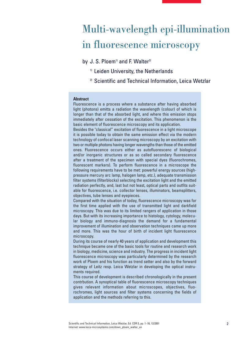
Multi-wavelength epi-illumination in fluorescence microscopy by J. S. Ploem 1) and F. Walter 2) 1) Leiden University, the Netherlands 2) Scientific and Technical Information, Leica Wetzlar Mitteilungen für Wissenschaft und Technik Scientific and Technical Information Edition CDR 5, pp. 1–16,12/2001
Transcript of Mitteilungen Scientific and für Wissenschaft Technical und ...
Multi-wavelength epi-illuminationin fluorescence microscopyby J. S. Ploem1) and F. Walter2)
1) Leiden University, the Netherlands2) Scientific and Technical Information, Leica Wetzlar
Mitteilungenfür Wissenschaftund Technik
Scientific andTechnicalInformation Edition CDR 5, pp. 1–16,12/2001
Scientific and Technical Information, Leica Wetzlar, Ed. CDR 5, pp. 1–16, 12/2001Internet: www.leica-microsystems.com/down_ploem_walter_en
2
Multi-wavelength epi-illuminationin fluorescence microscopyby J. S. Ploem1) and F. Walter2)
1) Leiden University, the Netherlands2) Scientific and Technical Information, Leica Wetzlar
AbstractFluorescence is a process where a substance after having absorbedlight (photons) emitts a radiation the wavelength (colour) of which islonger than that of the absorbed light, and where this emission stopsimmediately after cessation of the excitation. This phenomenon is thebasic element of fluorescence microscopy and its application.Besides the "classical” excitation of fluorescence in a light microscopeit is possible today to obtain the same emission effect via the moderntechnology of confocal laser scanning microscopy by an excitation withtwo or multiple photons having longer wavengths than those of the emittedones. Fluorescence occurs either as autofluorescenc of biologicaland/or inorganic structures or as so called secondary fluorescenceafter a treatment of the specimen with special dyes (fluorochromes,fluorescent markers). To perform fluorescence in a microscope thefollowing requirements have to be met: powerful energy sources (high-pressure mercury arc lamp, halogen lamp, etc.), adequate transmissionfilter systems (filterblocks) selecting the excitation light and the emittedradiation perfectly, and, last but not least, optical parts and outfits suit-able for fluorescence, i.e. collector lenses, illuminators, beamsplitters,objectives, tube lenses and eyepieces.Compared with the situation of today, fluorescence microscopy was forthe first time applied with the use of transmitted light and darkfieldmicroscopy. This was due to its limited rangers of application in thosedays. But with its increasing importance to histology, cytology, molecu-lar biology and immuno-diagnosis the demand for a fundamentalimprovement of illumination and observation techniques came up moreand more. This was the hour of birth of incident light fluorescencemicroscopy.During its course of nearly 40 years of application and development thistechnique became one of the basic tools for routine and research workin biology, medicine, science and industry. The progress in incident lightfluorescence microscopy was particularly determined by the researchwork of Ploem and his function as trend setter and also by the forwardstrategy of Leitz resp. Leica Wetzlar in developing the optical instru-ments required. This course of development is described chronologically in the presentcontrbution. A synoptical table of fluorescence microscopy techniquesgives relevant information about microscopes, objectives, fluo-rochromes, light sources and filter systems concerning the fields ofapplication and the methods referring to this.

3
FluorescenceFluorescence is a molecular phenomenon in which a substance absorbslight (excitation) and radiates light of longer wavelength (emission) for avery short period of time. When a fluorochrome absorbs light, energy in theform of photons is taken up, leading to excitation of electrons to higher ener-gy states. The process of absorption of photons is extremely rapid and isimmediately followed by a return to lower energy states, which is thenaccompanied by emission of photons, which can be observed if light isemitted in the visual range.
This short duration (nanoseconds) distinguishes it from other forms of lumi-nescence such as phosphorescence. The difference in wavelengthsbetween the excitation and emission peaks is referred to as the Stokesshift. Fluorochromes with a large Stokes shift are easy to excite and toobserve their emission in a fluorescence microscope. With transmitted-light illumination, a small Stokes shift may make it impossible to illuminatea fluorochrome at its excitation peak and to observe the fluorescencecolour at its emission peak. Confocal laser scanning fluorescence microscopy enables two-photonexcitation with photons of longer wave-length than the emitted light. Theelectron is then brought into its excited state with two photons of half therequired energy, arriving simultaneously. In most cases the electron endsup in the same excited state as with normal single-photon excitationbefore it drops down to the ground state. Similarly, the fluorescence emittedis similar to that given off by normal single-photon excitation.
FluorochromesMany molecules, both non-organic and organic, show fluorescence emis-sion, especially with excitation using high energy radiation. When plant oranimal tissue is excited with UV-light very often a bluish fluorescenceemission is observed which is called primary fluorescence, or autofluo-rescence [7, 8]. Naturally occurring substances often have very broadexcitation and emission spectra. With the development of molecular bio-logy, research has been focussed on special dyes with bright fluorescenceto distinguish them from possible autofluorescence. The dyes used toselectively stain biologically important molecules are called fluoro-chromes. When conjugated to antibodies or nucleic acids, they arereferred to as fluorescent markers or probes. Today fluorochromes areavailable with peak emissions in the violet, blue, green, orange, red andnear-infrared regions of the spectrum. The possibility to excite fluoro-chromes with orange and red light and detect the red and infrared fluo-rescence with a photomultiplier or a CCD-camera has extended fluores-cence microscopy beyond the visual range. The excitation and emission ofa fluorochrome may shift with changes in cellular environment. Some dyesare especially chosen because their excitation or emission spectra areshifted, following changes in concentration of some ions in the intracellularmedium such as calcium, natrium, and of the pH.
4
Early developments in epi-illuminationfluorescence microscopyFor a review of the history of fluorescence microscopy the reader isreferred to Kasten [11]. Epi-illumination (vertically incident exciting light)was used already by Policard and Paillot [32]. Several instruments weremade by Leitz (Leica), Bausch & Lomb, Reichert and Zeiss, which werepartially based on suggestions by Ellinger and Hirt [4, 5], Singer [37] andMehler and Pick [16, 19]. An early Leitz (Leica) fluorescence epi-illumina-tion system was described by Haitinger [6]. For more details on the evolu-tion of epi-illumination fluorescence microscopy the reader is referred toRost [34] and for early applications of incident-light fluorescence micro-scopy to Hauser [7].
A major contribution in epi-illumination fluorescence microscopy was theintroduction of a dichromatic mirror for incident illumination with UV light byBrumberg and Krylova [2]. Epi-illumination has definite optical advantagesbecause, unlike transmitted illumination where the condenser and theobjective have independent optical axes which must be perfectly aligned.The objective functions both as a condenser and as a light-collectingobjective, avoiding all alignment problems. The separation of fluorescenceemission from excitation light, using a dichroic beamspitter, is much easierthan with transmittted light fluorescence microscopy, These possibilitiesdid, however, not lead to a general acceptance by industrial microscopemanufacturers of epi-illumination for routine fluorescence microscopy. Themain reason for this could have been that transmitted-light darkfield UVexcitation gave already excellent results in most applications of fluores-cence microscopy [17]. Its replacement by UV epi-illumination would nothave had significant advantages. The use of transmitted light using a dark-field condenser remained the industry standard until the late sixties.
The rapidly growing interest in molecular biology, however, led to thedevelopment of many (monoclonal) antibodies for the detection of importantmacromolecules in the cell. To study the detailed morphological location ofseveral macromolecules in the cellular organelles, fluorescent markerswith different colours were increasingly used. UV excitation – as usedtraditionally for fluorescence microscopy – was not optimally suited fordetecting multiple fluorochromes simultaneously in a cell.
Around 1962 Ploem started work in collaboration with Schott on the deve-lopment of dichroic beamspitters for reflection of blue and green light forfluorescence microscopy using epi-illumination. At the time of his firstcommunication [1965] and publication on epi-illumination with narrowband blue and green light [21], he was not aware of the development of adichroic beamsplitter for UV excitation with incident light by Brumberg andKrylova [2]. Neither was the Leitz company, from which he obtained an"Opak" epi-illuminator with a neutral beamsplitter. This illuminator had tobe modified to contain a slider in the incident light path containing fourdichroic beamsplitters, for respectively UV, violet , blue and green excita-tion light. This device, developed at the University of Amsterdam, permit-ted the easy exchange of different dichroic beamsplitters in the incidentlight path (Fig. 1a). The wavelength of the excitation light could thus beeasily and rapidly changed.

5
Soon it became clear that excitation with narrow-bandblue and green light opened optimal possibilities for thedetection of the widely used immunofluorescence labelsfluorescein-isothiocyanate (FITC) and tetramethylrho-damine isothiocyanate (TRITC). The use of blue and greenexcitation also minimized autofluorescence of tissue com-ponents, an undesired effect encountered with conven-tional transmitted illumination with UV light. FITC could nowbe excited with narrow band blue light (using a band inter-ference filter with a half width of 16 nm), close to the exci-tation maximum at 490 nm (long wavelength blue), withclear observation of the green fluorescence peak emissionat 520 nm. Autofluorescence of tissue components wasminimized (Fig. 2a, b) resulting in a high image contrast. Ex-citation of FITC near its excitation maximum enabled suchan efficient excitation that even a mercury high-pressure
arc lamp, having no strong emission peak in the blue wavelength range,could be used. Furthermore epi-illumination with a green reflectingdichroic mirror enabled for the first time the excitation of Feulgen-pararosaniline with the strong mercury emission line at 546 nm (Fig. 3a, b).
In his second publication on the multi-wavelengths epi-illuminator,describing a Leitz prototype with four dichroic beam-spittters (Fig. 1b),Ploem [22] could acknowledge the contribution of Brumberg and Krylova[2]. The inaccessibility of Russian research in that time period, and theabsence of any major industrial development of epi-fluorescence micro-scopy in Russia or East Germany was the reason that Leitz had not beenaware earlier of such a development. The possibility to introduce epi-illu-mination with UV light, although useful for several applications, had notbeen a motive for a new technological development at Leitz, since theyhad already excellent transmitted dark field UV excitation available. The
Fig. 1a:Fluorescence multi-wavelenghtsepi-illuminator with four dichroicbeam-splitters mounted in a slider,for incident illumination with UV,violet, blue and green excitation light.Constructed at the University ofAmsterdam (Ploem, 1965).
Fig. 1b:Leitz prototype (not commercialized)multi-wavelenght epi-illuminator with fourdichroic beam-splitters mounted in a slider(Ploem, 1967).
Fig. 1c:Leitz epi-illuminator with four exchangeable filter cubes (blocks) [Kraft, 1972].

6
increasing world-wide use of routine immunofluorescence microscopy inmedical diagnosis and molecular biology research could, however, profitfrom the new possibility of epi-illumination using narrow band excitationwith blue and green light. Since standard high-pressure mercury arclamps could be used, this seemed a practical proposition.
Subsequently Leitz developed a novel multi-wavelength fluorescence epi-illuminator (Leitz PLOEMOPAK) with four rotating dichroic beamsplittersfor respectively UV, violet, blue and green light [13]. In successive genera-tions of Leitz illuminators (containing four dichroic beamsplitters) barrierfilters and a rotating turret for excitation filters were added. Finally an ele-gant epi-illuminator was constructed by Kraft [15] containing multiple setsof a combination of an excitation filter, a dichroic beamsplitter and a bar-rier or emission filter, mounted together in a filter cube, also called filterblock (Fig. 4). Since this illuminator permitted the filter cubes to be rapidlyturned into the optical light path, multi-wavelength illumination of the samesection of tissue became a practical proposition. Moreover, the four filtercubes in the illuminator could be exchanged by the user (Fig. 1c). Differentsets of four filter cubes could be assembled, chosen from many filter
Fig. 2a: Tissue cells marked with an immunolabel (FITC) illuminatedwith wide-band UV excitation. Note the tissue structure with blueautofluorescence.
Fig. 3a: Liver tissue. Nuclei stained with Feulgen-pararosanilin forDNA, and visualized with transmitted green light. This stain was knownas absorbing stain and not known to be fluorescent. One on the nucleiis illuminated with incident narrow-band green light (546 nm) resultingin a red fluorescence emission.
Fig. 2b: Same tissue and same immunostaining with FITC label illumi-nated with epi-illumination using narrow-band blue (490 nm) light. Notethe increased image contrast (Ploem, 1967).
Fig. 3b: Liver tissue. Nuclei stained with Feulgen-pararosaniline forDNA. Epi-illumination with narrow band green light (546 nm) and adichroic beam splitter for reflecting green light. Probably the first example of microscope excitation with green light (Ploem,1965). Notelarge image contrast.
7
cubes, containing combinations of excitation, barrier filters and dichroicbeamsplitters, developed for different applications. Following suggestionsby Ploem, Leitz also produced an inverted microscope with epi-illumina-tion (Fig. 5a, b). For a review of the Leitz PLOEMOPAK illuminator for multi-wavelength fluorescence microscopy, the reader is referred to a review byPluta [31]. The Leitz (Leica) filter cube system was so efficient that now, 39 years later,similar types of filter cubes are still used by most microscope manufacturersfor multi-wavelength fluorescence microscopy. This development finallyled within Leica to the development of automated multi-wavelength fluo-rescence epi-illuminators accommodating eight filter cubes for variouswavelength ranges (Fig. 5c). When switching between filter cubes, pixelshift on the computer monitor is avoided or stays below the resolutionpower of a 35 mm film due to a 0-pixel shift technology. This illuminator isnow used for fluorescence in situ hybridisation methods (FISH) in the studyof chromosomes.
Ploem [24, 25, 26, 27, 28], van der Ploeg and Ploem [20] and Nairn andPloem [18] further explored the filter combinations that had to be devel-oped for many biomedical applications. This was done in collaborationwith Schott and Leitz. Rygaard and Olson [35] developed a novel short-wave pass high transmission interference filter with a very high transmis-sion for blue light and a sharp cut-off towards wavelengths longer than 490nm.
Ploem [23] combined this SP filter with a 1 mm GG 455 filter from Schott,which blocked UV excitation, and suggested the development by Balzersof a similar filter ( SP 560 = KP560) for excitation with green light and a fil-ter for excitation with violet light (LP 425 = KP 425). The latter filter wasapplied in the investigation of neurotransmitters [25]. In Fig. 6a, b the re-sulting blue fluorescence can be observed.
From the optical industry side, early contributions and reviews on thesedevelopments were written by Kraft [14], Walter [39, 40], Trapp [38] andHerzog [8].
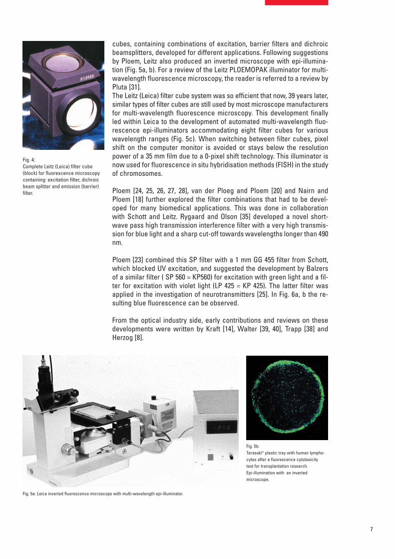
Fig. 4:Complete Leitz (Leica) filter cube(block) for fluorescence microscopycontaining: excitation filter, dichroicbeam splitter and emission (barrier)filter.
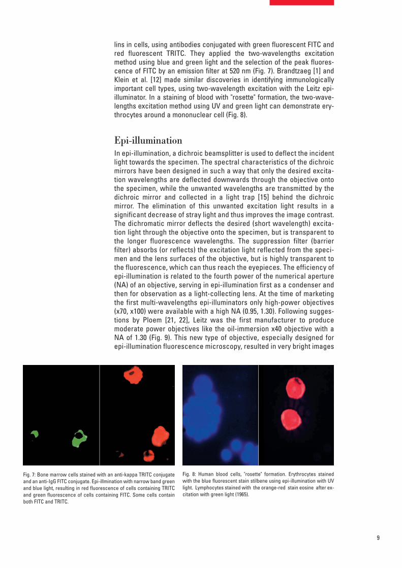
Fig. 5b:Terasaki® plastic tray with human lympho-cytes after a fluorescence cytotoxicitytest for transplantation research.Epi-illumination with an invertedmicroscope.
Fig. 5a: Leica inverted fluorescence microscope with multi-wavelength epi-illuminator.

8
The main classes of filters used in epi-illumination fluorescence micro-scopy were defined in (1) the primary excitation filters LP (long pass) andSP (short pass) – in the German literature known as KP filter – and (2) thesecondary filters such as barrier filters and emission filters [23]. The latterwere also described as fluorescence selection filters; these are forinstance used to limit the observation to the peak fluorescence at 520 nmof FITC. A recent extensive review on filters for fluorescence microscopyhas been given by Reichman [33]. Cormane [3] was the first to demonstrate that narrow band blue light epi-illumination of the fluorescent label FITC gave an optimal contrast inimmunofluorescence studies of human skin disease. Transmitted-lightexcitation with UV light used to cause such a strong autofluorescence ofelastic fibres in the skin, so that visualization of the fluorescent antibodywas severely hindered.
The pioneering work of Leitz in epi-illumination fluorescence microscopycoincided in the seventies with a worldwide increase in the application ofimmunofluorescence and other molecular biology methods like FISH inmedical diagnosis and research. Hijmans et al [9, 10] were the first to de-monstrate the usefulness of the new Leitz multi-wavelength excitation epi-illuminator for the selective detection of certain classes of immunoglobu-
Fig. 5c:Leitz (Leica) motorized epi-illuminatorwith eight filter cubes (blocks)
Fig. 6a: Mesenterium of the rat with small blood vessel surrounded bya blue fluorescent adrenergic (CA) nerve-plexus and yellow fluores-cent mast (5-HT) cells. Formaldehyde-induced neurotransmitter fluo-rescence of CA and 5-HT fluorophores.
Fig. 6b: Same tissue and staining as is Fig. 6a: Epi-illumination with nar-row-band violet excitation light (LP 3mm GG 400 and SP(KP)425 inter-ference filter), a dichroic beam-splitter 495 nm, reflecting violet lightand a barrier filter LP 460 nm. This filter-cube permittted for the firsttime the observation of blue fluorescent adrenergic nerve fibers, dis-tinctly different from yellow fluorescent mast cells (Ploem, 1971).
9
lins in cells, using antibodies conjugated with green fluorescent FITC andred fluorescent TRITC. They applied the two-wavelengths excitationmethod using blue and green light and the selection of the peak fluores-cence of FITC by an emission filter at 520 nm (Fig. 7). Brandtzaeg [1] andKlein et al. [12] made similar discoveries in identifying immunologicallyimportant cell types, using two-wavelength excitation with the Leitz epi-illuminator. In a staining of blood with "rosette" formation, the two-wave-lengths excitation method using UV and green light can demonstrate ery-throcytes around a mononuclear cell (Fig. 8).
Epi-illuminationIn epi-illumination, a dichroic beamsplitter is used to deflect the incidentlight towards the specimen. The spectral characteristics of the dichroicmirrors have been designed in such a way that only the desired excita-tion wavelengths are deflected downwards through the objective ontothe specimen, while the unwanted wavelengths are transmitted by thedichroic mirror and collected in a light trap [15] behind the dichroic mirror. The elimination of this unwanted excitation light results in a significant decrease of stray light and thus improves the image contrast.The dichromatic mirror deflects the desired (short wavelength) excita-tion light through the objective onto the specimen, but is transparent tothe longer fluorescence wavelengths. The suppression filter (barrier filter) absorbs (or reflects) the excitation light reflected from the speci-men and the lens surfaces of the objective, but is highly transparent tothe fluorescence, which can thus reach the eyepieces. The efficiency ofepi-illumination is related to the fourth power of the numerical aperture(NA) of an objective, serving in epi-illumination first as a condenser andthen for observation as a light-collecting lens. At the time of marketingthe first multi-wavelengths epi-illuminators only high-power objectives(x70, x100) were available with a high NA (0.95, 1.30). Following sugges-tions by Ploem [21, 22], Leitz was the first manufacturer to produce moderate power objectives like the oil-immersion x40 objective with aNA of 1.30 (Fig. 9). This new type of objective, especially designed forepi-illumination fluorescence microscopy, resulted in very bright images
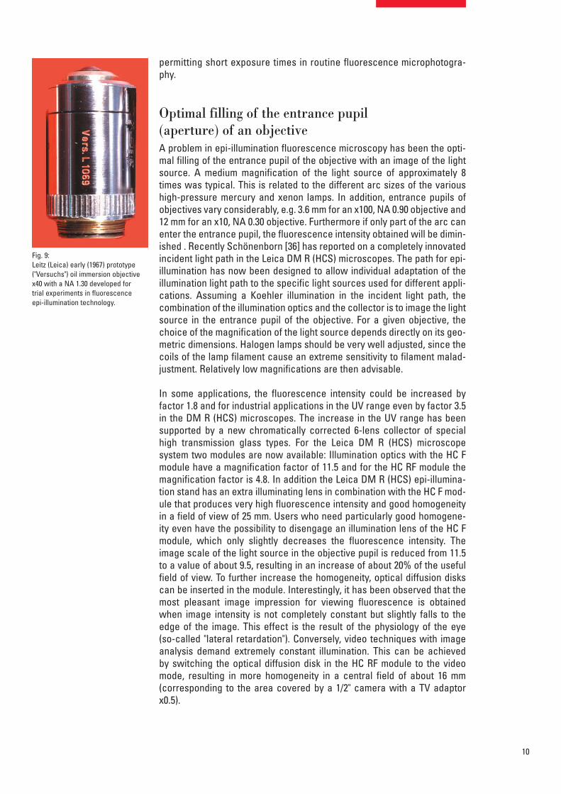
Fig. 7: Bone marrow cells stained with an anti-kappa TRITC conjugateand an anti-IgG FITC conjugate. Epi-illmination with narrow band greenand blue light, resulting in red fluorescence of cells containing TRITCand green fluorescence of cells containing FITC. Some cells containboth FITC and TRITC.
Fig. 8: Human blood cells, "rosette" formation. Erythrocytes stainedwith the blue fluorescent stain stilbene using epi-illumination with UVlight. Lymphocytes stained with the orange-red stain eosine after ex-citation with green light (1965).
10
permitting short exposure times in routine fluorescence microphotogra-phy.
Optimal filling of the entrance pupil(aperture) of an objectiveA problem in epi-illumination fluorescence microscopy has been the opti-mal filling of the entrance pupil of the objective with an image of the lightsource. A medium magnification of the light source of approximately 8times was typical. This is related to the different arc sizes of the varioushigh-pressure mercury and xenon lamps. In addition, entrance pupils ofobjectives vary considerably, e.g. 3.6 mm for an x100, NA 0.90 objective and12 mm for an x10, NA 0.30 objective. Furthermore if only part of the arc canenter the entrance pupil, the fluorescence intensity obtained will be dimin-ished . Recently Schönenborn [36] has reported on a completely innovatedincident light path in the Leica DM R (HCS) microscopes. The path for epi-illumination has now been designed to allow individual adaptation of theillumination light path to the specific light sources used for different appli-cations. Assuming a Koehler illumination in the incident light path, thecombination of the illumination optics and the collector is to image the lightsource in the entrance pupil of the objective. For a given objective, thechoice of the magnification of the light source depends directly on its geo-metric dimensions. Halogen lamps should be very well adjusted, since thecoils of the lamp filament cause an extreme sensitivity to filament malad-justment. Relatively low magnifications are then advisable.
In some applications, the fluorescence intensity could be increased byfactor 1.8 and for industrial applications in the UV range even by factor 3.5in the DM R (HCS) microscopes. The increase in the UV range has beensupported by a new chromatically corrected 6-lens collector of specialhigh transmission glass types. For the Leica DM R (HCS) microscope system two modules are now available: Illumination optics with the HC Fmodule have a magnification factor of 11.5 and for the HC RF module themagnification factor is 4.8. In addition the Leica DM R (HCS) epi-illumina-tion stand has an extra illuminating lens in combination with the HC F mod-ule that produces very high fluorescence intensity and good homogeneityin a field of view of 25 mm. Users who need particularly good homogene-ity even have the possibility to disengage an illumination lens of the HC Fmodule, which only slightly decreases the fluorescence intensity. Theimage scale of the light source in the objective pupil is reduced from 11.5to a value of about 9.5, resulting in an increase of about 20% of the usefulfield of view. To further increase the homogeneity, optical diffusion diskscan be inserted in the module. Interestingly, it has been observed that themost pleasant image impression for viewing fluorescence is obtainedwhen image intensity is not completely constant but slightly falls to theedge of the image. This effect is the result of the physiology of the eye (so-called "lateral retardation"). Conversely, video techniques with imageanalysis demand extremely constant illumination. This can be achieved by switching the optical diffusion disk in the HC RF module to the videomode, resulting in more homogeneity in a central field of about 16 mm (corresponding to the area covered by a 1/2" camera with a TV adaptorx0.5).
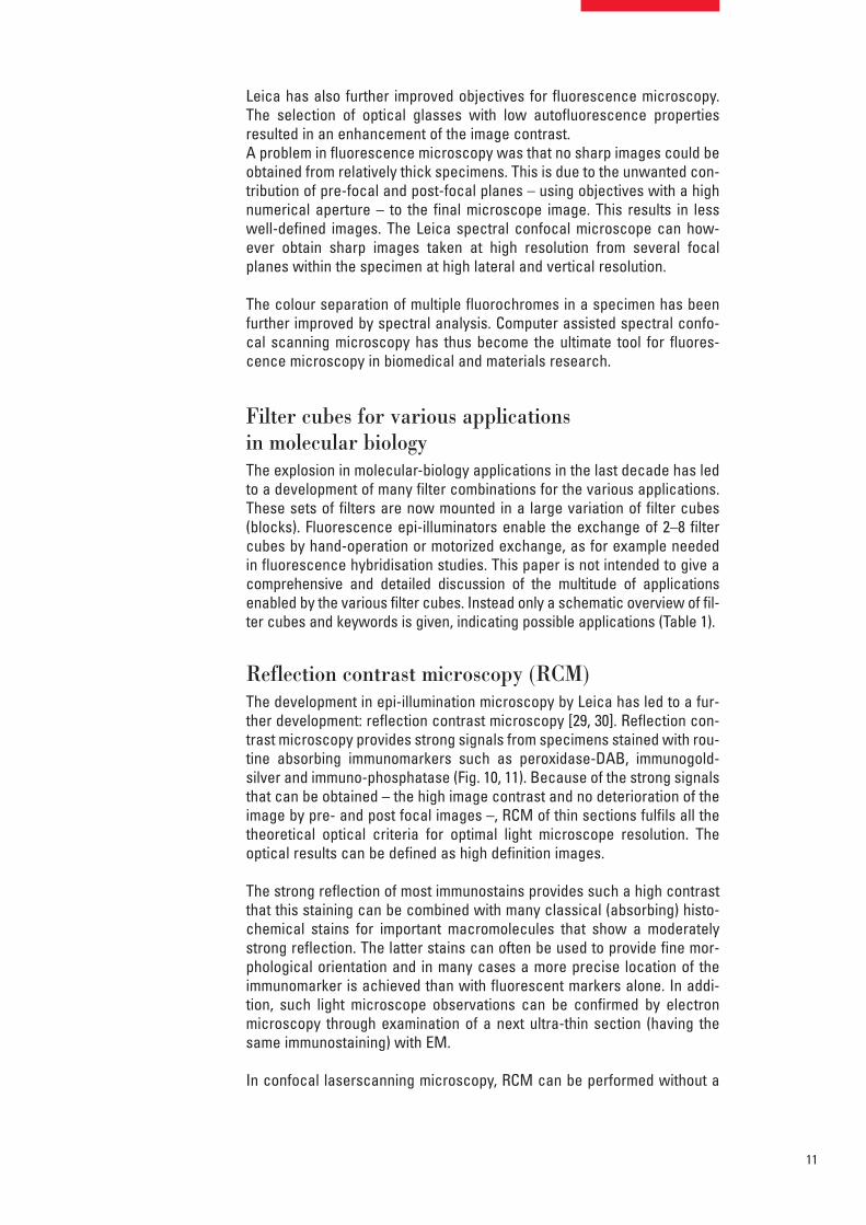
Fig. 9:Leitz (Leica) early (1967) prototype("Versuchs") oil immersion objectivex40 with a NA 1.30 developed fortrial experiments in fluorescenceepi-illumination technology.
11
Leica has also further improved objectives for fluorescence microscopy.The selection of optical glasses with low autofluorescence propertiesresulted in an enhancement of the image contrast.A problem in fluorescence microscopy was that no sharp images could beobtained from relatively thick specimens. This is due to the unwanted con-tribution of pre-focal and post-focal planes – using objectives with a highnumerical aperture – to the final microscope image. This results in lesswell-defined images. The Leica spectral confocal microscope can how-ever obtain sharp images taken at high resolution from several focalplanes within the specimen at high lateral and vertical resolution.
The colour separation of multiple fluorochromes in a specimen has beenfurther improved by spectral analysis. Computer assisted spectral confo-cal scanning microscopy has thus become the ultimate tool for fluores-cence microscopy in biomedical and materials research.
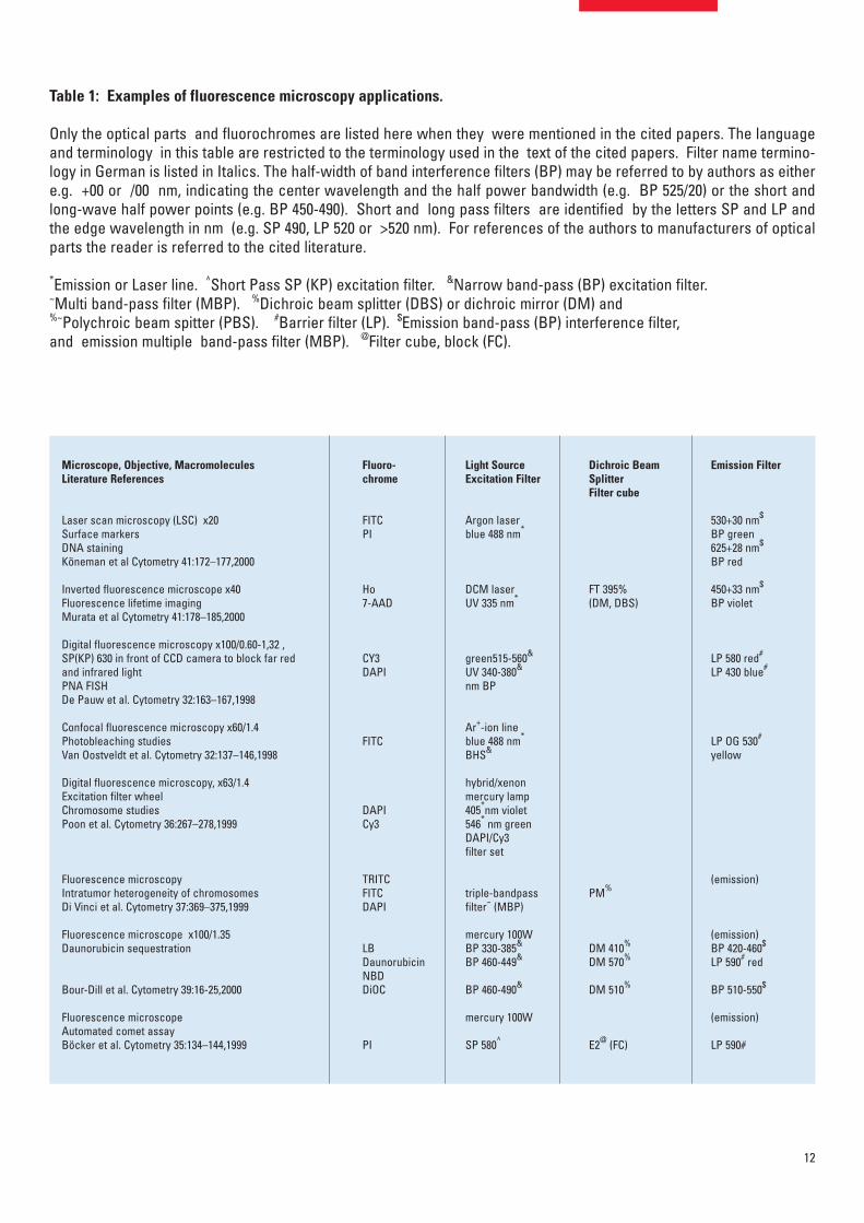
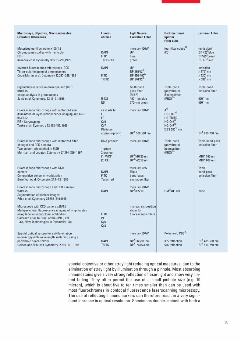
Filter cubes for various applicationsin molecular biologyThe explosion in molecular-biology applications in the last decade has ledto a development of many filter combinations for the various applications.These sets of filters are now mounted in a large variation of filter cubes(blocks). Fluorescence epi-illuminators enable the exchange of 2–8 filtercubes by hand-operation or motorized exchange, as for example neededin fluorescence hybridisation studies. This paper is not intended to give acomprehensive and detailed discussion of the multitude of applicationsenabled by the various filter cubes. Instead only a schematic overview of fil-ter cubes and keywords is given, indicating possible applications (Table 1).
Reflection contrast microscopy (RCM)The development in epi-illumination microscopy by Leica has led to a fur-ther development: reflection contrast microscopy [29, 30]. Reflection con-trast microscopy provides strong signals from specimens stained with rou-tine absorbing immunomarkers such as peroxidase-DAB, immunogold-silver and immuno-phosphatase (Fig. 10, 11). Because of the strong signalsthat can be obtained – the high image contrast and no deterioration of theimage by pre- and post focal images –, RCM of thin sections fulfils all thetheoretical optical criteria for optimal light microscope resolution. Theoptical results can be defined as high definition images.
The strong reflection of most immunostains provides such a high contrastthat this staining can be combined with many classical (absorbing) histo-chemical stains for important macromolecules that show a moderatelystrong reflection. The latter stains can often be used to provide fine mor-phological orientation and in many cases a more precise location of theimmunomarker is achieved than with fluorescent markers alone. In addi-tion, such light microscope observations can be confirmed by electronmicroscopy through examination of a next ultra-thin section (having thesame immunostaining) with EM.
In confocal laserscanning microscopy, RCM can be performed without a
12
Table 1: Examples of fluorescence microscopy applications.
Only the optical parts and fluorochromes are listed here when they were mentioned in the cited papers. The languageand terminology in this table are restricted to the terminology used in the text of the cited papers. Filter name termino-logy in German is listed in Italics. The half-width of band interference filters (BP) may be referred to by authors as eithere.g. +00 or /00 nm, indicating the center wavelength and the half power bandwidth (e.g. BP 525/20) or the short andlong-wave half power points (e.g. BP 450-490). Short and long pass filters are identified by the letters SP and LP andthe edge wavelength in nm (e.g. SP 490, LP 520 or >520 nm). For references of the authors to manufacturers of opticalparts the reader is referred to the cited literature.
*Emission or Laser line. ^Short Pass SP (KP) excitation filter. &Narrow band-pass (BP) excitation filter. ~Multi band-pass filter (MBP). %Dichroic beam splitter (DBS) or dichroic mirror (DM) and %~Polychroic beam spitter (PBS). #Barrier filter (LP). $Emission band-pass (BP) interference filter,and emission multiple band-pass filter (MBP). @Filter cube, block (FC).
Microscope, Objective, Macromolecules Literature References
Laser scan microscopy (LSC) x20 Surface markers DNA stainingKöneman et al Cytometry 41:172–177,2000
Inverted fluorescence microscope x40 Fluorescence lifetime imagingMurata et al Cytometry 41:178–185,2000
Digital fluorescence microscopy x100/0.60-1,32 , SP(KP) 630 in front of CCD camera to block far redand infrared light PNA FISHDe Pauw et al. Cytometry 32:163–167,1998
Confocal fluorescence microscopy x60/1.4 Photobleaching studiesVan Oostveldt et al. Cytometry 32:137–146,1998
Digital fluorescence microscopy, x63/1.4 Excitation filter wheelChromosome studiesPoon et al. Cytometry 36:267–278,1999
Fluorescence microscopyIntratumor heterogeneity of chromosomesDi Vinci et al. Cytometry 37:369–375,1999
Fluorescence microscope x100/1.35Daunorubicin sequestration
Bour-Dill et al. Cytometry 39:16-25,2000
Fluorescence microscopeAutomated comet assayBöcker et al. Cytometry 35:134–144,1999
Fluoro-chrome
FITCPI
Ho7-AAD
CY3DAPI
FITC
DAPICy3
TRITCFITCDAPI
LBDaunorubicinNBDDiOC
PI
Light Source Excitation Filter
Argon laserblue 488 nm*
DCM laserUV 335 nm*
green515-560&
UV 340-380&
nm BP
Ar+-ion lineblue 488 nm*
BHS&
hybrid/xenonmercury lamp405*nm violet 546* nm greenDAPI/Cy3filter set
triple-bandpassfilter~ (MBP)
mercury 100WBP 330-385&
BP 460-449&
BP 460-490&
mercury 100W
SP 580^
Dichroic BeamSplitterFilter cube
FT 395% (DM, DBS)
PM%
DM 410%
DM 570%
DM 510%
E2@ (FC)
Emission Filter
530+30 nm$
BP green625+28 nm$
BP red
450+33 nm$
BP violet
LP 580 red#
LP 430 blue#
LP OG 530#
yellow
(emission)
(emission)BP 420-460$
LP 590# red
BP 510-550$
(emission)
LP 590#
13
Microscope, Objective, Macromolecules Literature References
Motorized epi-illuminator x100/1.3Chromosome studies with multicolor FISHKuzobek et al. Cytometry 36:279–293,1999
Inverted fluorescence microscope, CCDThree-color imaging of chromosomesCoco-Martin et al. Cytometry 32:327–336,1998
Digital fluorescence microscope and (CCD) x40/0.75 Image analysis of granulocytesSz cs et al. Cytometry: 33:19–31,1998
Fluorescence microscope with motorized epi-illuminator, delayed luminescence imaging and CCD,x63/1.32FISH KaryotypingTanke et al. Cytometry 33:453-459, 1998
Fluorescence microscope with motorized filterchanger and CCD camera Two colour ratio method in FISHMorrison and Legator. Cytometry 27:314–326, 1997
Fluorescence microscope with CCD cameraComparitive genomic hybridizationBornfleth et al. Cytometry 24:1–13, 1996
Fluorescence microscope and CCD camera, x20/0.75 Segmentation of nuclear imagesPrice et al. Cytometry 25:303–316,1996
Microscope with CCD camera x30/0.5 Multiparameter fluorescence imaging of lymphocytesusing labelled monoclonal antibodiesGalbraith et al. In Proc. of the SPIE , Vol1063, New Technologies in Cytometry,1989
Special optical system for epi-illuminationmicroscopy with wavelength switching using apolychroic beam-splitterHeiden and Tribukait Cytometry, 20:95–101, 1995.
Fluoro-chrome
DAPIFITCTexas-red
DAPI
FITCTRITC
R 123EB
cascade blF LR Cy5Cy7Platinumcoproporphyrin
DNA probes:
1 green 2 orange(1) WCP (2) CEP
DAPIFITCTexas red
DAPI
FITCPECy5Cy3
DAPITRITC
Light Source Excitation Filter
mercury 100WUVbluegreen
UVBP 365/12&
BP 450-490&
BP 546/12&
Multi-band pass filter(MBP) 490~ nm blue570~nm green
mercury 100W
BP& 500-560 nm
mercury 100W
BP&510/20 nmBP&572/18 nm
mercury 50WTriple band-pass excitation filter
mercury 100WBP&365/10
manual, six-positionslider for fluorescence filters
mercury 100W
BP& 365/33 nmBP& 546/23 nm
Dichroic BeamSplitterFilter cube
four filter cubes@
(FC)
Triple-band (polychroic)Beamsplitter(PBS)%~
A@
HQ-FITC@
HQ-TRITCHQ-Cy5@
HQ-Cy7@
DBS 580% nm
Triple-band (polychroic)beamsplitter(PBS)%~
DM%400 nm
Polychroic PBS%
365 reflection546 reflection
Emission Filter
(emission)BP 425$blueBP525$greenBP 615$ red
emission> 379# nm> 520# nm> 593# nm
Triple-band emission filter
520~ nm580~ nm
BP$ 600-700 nm
Triple band-passemission filter:
MBP~535 nmMBP~606 nm
Tripleband-passemission filter
none
BP$ 435-500 nm BP$ 590-750 nm
special objective or other stray light reducing optical measures, due to theelimination of stray light by illumination through a pinhole. Most absorbingimmunostains give a very strong reflection of laser light and show very lim-ited fading. They often permit the use of a small pinhole size (e.g. 10micron), which is about five to ten times smaller than can be used withmost fluorochromes in confocal fluorescence laserscanning microscopy.The use of reflecting immunomarkers can therefore result in a very signif-icant increase in optical resolution. Specimens double-stained with both a

14
fluorochrome and the Leica Spectral Confocal Laserscanning Microscopeproviding new possibilities for multiple markers can easily examine areflecting immunomarker.
RCM uses a fluorescence microscope stand, epi-illuminator and highpressure lamps. In the fluorescence epi-illuminator an extra polarizer filtercube, containing a polarizer, reflector, and an analyser must be inserted(Fig. 12). Also a reflection contrast (RC) diaphragm module (containing thecentral stop system) must be brought in the incident light path. This RCdiaphragm module adapts sliding sets with central stops and/or aperturediaphragms. Furthermore a special objective developed for reflection con-trast microscopy, the Leica RC M-plan oil-immersion x100/1.25 RCM objec-tive equipped with a λ/4 plate at the front lens, should be added to the setof objectives (for fluorescence microscopy) on the turret of the objectiverevolver.
In reflected-light microscopy, contrast is based on differences in reflectionintensities (= reflectance). In this type of microscopy it should be remind-ed that reflection of light occurs at every optical boundary, that is when therefractive index and/or the absorption index change. For biological speci-mens showing reflectance of less than 1% and mostly less than 0.2%, it isalmost impossible to obtain a reflected light image with a conventionalmicroscope, due to the unwanted reflections inside the microscope tube.In reflection contrast microscopy, a combination of two methods is used toreduce glare due to scattered light. The incident light is made into a ring-shaped cone of light by the insertion of a central stop (an aperturediaphragm provided with a central stop, creating an annular aperture) inthe incident light path at a plane conjugated with the back focal (aperture)plane of the objective. As a second method, unwanted scattered reflectedlight is reduced by the use of the "antiflex" method. Light reflected insidethe microscope is suppressed by using crossed polarizers, with the result
Fig. 10: Reflection contrast microscopy (RCM). Mouse peritonealmacrophages adhering to a coverslip and stained with a monoclonalantibody to surface antigens. Immunoperoxidase staining. Thin exten-sions of filopodia, which are not visisble with brightfield microscopy,are visible bccause of the strong relfection of the DABox product.
Fig. 12:A filter cube (block) for reflectioncontrast microscopy, containing apolarizer, a neutral (50 %)beam-splitter and an analyzer.This filter cube (block) can beinserted into one of the positionsof a Leica epi-illuminator forfluorescence microscopy.
Fig. 11: Ultrathin section (ca. 35 nm) of kidney tissue: peroxidase DABstaining. Linear staining patterns of the glomerulus observed withreflection contrast microscopy present often sharper images than withfluorescence microscopy.

15
that only the light reflected from the specimen is passed on to the eyes. Tothat purpose an objective is provided with a quarter-wave plate in the frontlens of the objective. The passing of the light through the λ/4 plate (down-wards to the specimen and upwards after reflection from the specimen)change the polarization direction of the light with 2x45° = 90°.
Bibliography[1] Brandtzaeg, P.: Two types of IgA Immunocytes in Man. Nature (New Biology) 243,
142–143,1973.[2] Brumberg, E. M., Krylova, T. N.: O fluoreschentnykh mikroskopopak. Zh. obshch. biol.
14, 461, 1953.[3] Cormane, R. H., Szabo, E., Hauge, L. S.: Immunofluorescence of the skin: the interpre-
tation of the staining of blood vessels and connective tissue aided by new techniques.Br. J. Derm. 82, Supplement 5, 26–43, 1970.
[4] Ellinger, P., Hirt, A.: Mikroskopische Untersuchungen an lebenden Organen. I. Mitteil-lung: Methodik: Intravitalmikroskopie. Zeitschrift für Anatomie und Entwicklungs-Geschichte 90, 791–802,1929.
[5] Ellinger, P., Hirt, A.: Eine Methode zur Beobachtung lebender Organe mit starkstenVergrösserung im Lumineszenzlicht (Intravitalmikroskopie). Handbuch der Histologi-schen Arbeitsmethoden 15, 1753–1764. Urban & Schwarzenberg, Berlin & Vienna,1930.
[6] Haitinger, M.: Fluoreszenzmikroskopie. Akademische Verlagsgesellschaft, Geest &Portig K.G., Leipzig, 1959.
[7] Hauser, F.: Das Arbeiten mit auffallemdem Licht in der Mikroskopie, Academische Ver-lagsgesellschaft, Geest & Portig K.G., Leipzig, 1960.
[8] Herzog, F., Albini, B., Wick, G.: Comparison of filters used in immunofluorescent stain-ing procedures with fluoresceinisothiocyanate (FTIC) conjugates. Journal of Immunol.3, 211–220, 1973.
[9] Hijmans, W., Schuit, H. R. E., Klein, F.: An immunofluorescence procedure for thedetection of intracellular immunoglobulins. Clin. exp. Immunol. 4, 457–472, 1969.
[10] Hijmans, W., Schuit, H. R. E., Hulsing-Hesselink, E.: An immunofluorescence study onintracellular immunoglobulins in human bone marrow cells. Ann. N. Y. Acad. Sci. 177:290–305, 1971.
[11] Kasten, F. H.: The origins of modern fluorescence microscopy and fluorescenceprobes. In: E. Kohen and J. G. Hirschberg (eds), Cell Structure and Function by Micro-spectrophotometry. Academic Press, San Diego, 1989.
[12] Klein, G., Gergely, L., Goldstein, G.: Two-colour immunofluorescence studies on EBVdetermined antigens. Clin. exp. Immunol. 8, 593–602, 1971.
[13] Kraft, W.: Die Technologie des Fluoreszenzopak, Leitz Mitt. Wiss. u. Techn. IV/6,239–242, 1969.
[14] Kraft, W.: Ein neues FITC-Erregerfilter für die Routinefluoreszenz. Leitz Mitt. Wiss. u.Techn. V/2, 41–44, 1970.
[15] Kraft, W.: Fluorescence Microscopy and Instrument Requirements. Leitz Mitt. Wiss. u.Techn. V/7, 193–206, 1972.
[16] Mehler, L., Pick, J.: Über ein Mikroskop zur Untersuchung lebenden Gewebes. Vorläu-fig Mitteilung. Anatomische Anzeiger 75, 234–240, 1932.
[17] Nairn, R. C.: Fluorescent Protein Tracing. E. & S. Livingstone Ltd. Edinburgh and Lon-don, 1969.
[18] Nairn, R. C., Ploem, J. S.: Modern microscopy for immunofluorescence in clinicalimmunology. Leitz Sci. a. Techn. Information VI/3: 91–95, 1974.
[19] Pick, J.: Über ein Mikroskop zur Untersuchung lebenden Gewebes. II. Mitteillung. Zeit-schr. f. wiss. Mikroskopie 51, 257–262, 1934.
[20] Ploeg, M. van der, Ploem, J. S.: Filter combinations and light sources for fluorescencemicroscopy of quinacrine mustard or quinacrine stained chromosomes. Histochemie33: 61–70, 1973.
[21] Ploem, J. S.: Die Möglichkeit der Auflichtfluoreszenzmethoden bei Untersuchungenvon Zellen in Durchströmungskammern und Leightonröhren. Xth Symposium d.Gesellschaft f. Histochemie, 1965. Acta Histochem. Suppl. 7, 339–343, 1967.
[22] Ploem, J. S.: The use of a vertical illuminator with interchangeable dichroic mirrors for flu-orescence microscopy with incident light. Zeitschr. f. wiss. Mikroskopie 68, 129–142, 1967.

16
[23] Ploem, J. S.: A study of filters and light sources in immunofluorescence microscopy.Ann. N. Y. Acad. Sci. 177, 414–429, 1971.
[24] Ploem, J. S.: Immunofluorescence microscopy. In: E. H. Beutner and R. J. Nisengard(eds.), Defined Immunofluorescence in Clinical Immunopathology. pp 248–270. Manu-al for School of Medicine, State University of N.Y.at Buffalo, 1971.
[25] Ploem, J. S.: The microscopic differentiation of the colour of formaldehyde-inducedfluorescence. Prog. Brain Res., 34: 27–37, 1971.
[26] Ploem, J. S.: Immunofluorescence microscopy. In: E. H. Beutner, T. P. Chorzelski, S. F.Bean and R. E. Jordon (eds.), Immunopathology of the skin, Labeled Antibody Studies.pp. 248–270. Dowden, Hutchinson and Ross Inc., Stroudsburg, Penn. USA, 1973.
[27] Ploem, J. S.: Fluorescence Microscopy. In: A.J. Lacey (ed.), Light Microscopy in Biol-ogy: A Practical Approach, 2nd Edition. pp 163–186. Oxford University Press, 1998.
[28] Ploem, J. S., Tanke, H. J., Al, I., Deelder, A. M.: Recent developments in immunofluo-rescence microscopy and microfluorometry. In: W. Knapp, K. Holubar and G. Wick(eds), Immunofluorescence and related staining techniques. pp. 3–10. Elsevier/North-Holl. Biomedical Press, Amsterdam, New York, 1978.
[29] Ploem, J. S., Cornelese-ten Velde, I., Prins, F. A., Bonnet, J.: Reflection-ContrastMicroscopy: An Overview. Proceedings RMS 30, 185–192, 1995.
[30] Ploem, J. S., Cornelese-ten Velde, I., Prins, F. A., Bonnet, J., Heer, E. D.: Reflection-Con-trast Microscopy. Leitz Sci. u. Techn. Inform. XI/4, 98–113, 1997.
[31] Pluta, M.: Handbook: Advanced Light Microscopy. Specialized Methods Vol. 2. Else-vier. Amsterdam, 1989.
[32] Policard, A., Paillot, A.: Etude de la sécrétion de la soie à I'aide des rayons ultravio-lets filtrés (lumière de Wood). Comptes Rendus de l'Académie des Sciences Paris 181,378–380, 1925.
[33] Reichman, J.: Handbook of optical filters for fluorescence microscopy. Chroma Tech-nology Corporation, 2000.
[34] Rost, F. W. D.: Quantitative fluorescence microscopy. Cambridge University Press,1991.
[35] Rygaard, J., Olson W.: Interference filters for improved immunofluorescence micro-scopy. Acta Path. Microbiol. Scand. 76, 14, 1969.
[36] Schönenborn, J.: Leica Scientific and Technical Information. CDR 1, 37–46, 1988.[37] Singer, E.: A microscope for observations of fluorescence in living tissues. Science 75,
289–291, 1932.[38] Trapp, L.: Über Lichtquellen und Filter für die Fluoreszenzmikroskopie und über die Auf-
lichtfluoreszenzmethode bei Durchlichtpräparaten. Acta Histochemica suppl. VII, 327–338, 1967.
[39] Walter, F.: Eine Auflicht-Fluorescenz-Einrichtung für die Routinediagnose. Leitz Mitt.Wiss. u.Techn. IV/6, 186–187, 1968.
[40] Walter, F.: Fluoreszenzmikroskopie in Biologie und Medizin. Leitz Mitt. Wiss. u. Techn.V/2, 33–40, 1970.
Authors:Prof. em. J. S. Ploem, Pres. Kennedylaan 256, 2343 GX OEGSTGEEST, TheNetherlands; Dr. Friedrich Walter, Editor Scientific and Technical Informa-tion, Karl-Broll-Strasse 12, D-35619 Braunfels/Germany.